EP3324859B1 - Spindle for surgical drill with additional manual drive and surgical drill - Google Patents
Spindle for surgical drill with additional manual drive and surgical drill Download PDFInfo
- Publication number
- EP3324859B1 EP3324859B1 EP16734715.2A EP16734715A EP3324859B1 EP 3324859 B1 EP3324859 B1 EP 3324859B1 EP 16734715 A EP16734715 A EP 16734715A EP 3324859 B1 EP3324859 B1 EP 3324859B1
- Authority
- EP
- European Patent Office
- Prior art keywords
- ratchet
- torque
- output
- unit
- manual
- Prior art date
- Legal status (The legal status is an assumption and is not a legal conclusion. Google has not performed a legal analysis and makes no representation as to the accuracy of the status listed.)
- Active
Links
- 230000008878 coupling Effects 0.000 claims description 25
- 238000010168 coupling process Methods 0.000 claims description 25
- 238000005859 coupling reaction Methods 0.000 claims description 25
- 230000005540 biological transmission Effects 0.000 claims description 23
- 238000005553 drilling Methods 0.000 description 9
- 210000000988 bone and bone Anatomy 0.000 description 6
- 238000000034 method Methods 0.000 description 5
- 230000008569 process Effects 0.000 description 5
- 230000008859 change Effects 0.000 description 4
- 238000001356 surgical procedure Methods 0.000 description 3
- 230000008901 benefit Effects 0.000 description 2
- 239000000969 carrier Substances 0.000 description 2
- 230000001419 dependent effect Effects 0.000 description 2
- 210000003205 muscle Anatomy 0.000 description 2
- 230000035515 penetration Effects 0.000 description 2
- 230000003252 repetitive effect Effects 0.000 description 2
- 230000003213 activating effect Effects 0.000 description 1
- 230000006978 adaptation Effects 0.000 description 1
- 230000000903 blocking effect Effects 0.000 description 1
- 238000005516 engineering process Methods 0.000 description 1
- 239000004744 fabric Substances 0.000 description 1
- 239000012530 fluid Substances 0.000 description 1
- 230000036541 health Effects 0.000 description 1
- 230000010354 integration Effects 0.000 description 1
- 239000002655 kraft paper Substances 0.000 description 1
- 230000008376 long-term health Effects 0.000 description 1
- 230000007246 mechanism Effects 0.000 description 1
- 238000003801 milling Methods 0.000 description 1
- 230000036316 preload Effects 0.000 description 1
- 230000009467 reduction Effects 0.000 description 1
- 230000001105 regulatory effect Effects 0.000 description 1
- 230000035945 sensitivity Effects 0.000 description 1
- 230000001954 sterilising effect Effects 0.000 description 1
- 238000004659 sterilization and disinfection Methods 0.000 description 1
- 238000003786 synthesis reaction Methods 0.000 description 1
Images


Classifications
-
- A—HUMAN NECESSITIES
- A61—MEDICAL OR VETERINARY SCIENCE; HYGIENE
- A61B—DIAGNOSIS; SURGERY; IDENTIFICATION
- A61B17/00—Surgical instruments, devices or methods, e.g. tourniquets
- A61B17/16—Bone cutting, breaking or removal means other than saws, e.g. Osteoclasts; Drills or chisels for bones; Trepans
- A61B17/1613—Component parts
- A61B17/1622—Drill handpieces
- A61B17/1624—Drive mechanisms therefor
-
- A—HUMAN NECESSITIES
- A61—MEDICAL OR VETERINARY SCIENCE; HYGIENE
- A61B—DIAGNOSIS; SURGERY; IDENTIFICATION
- A61B17/00—Surgical instruments, devices or methods, e.g. tourniquets
- A61B17/16—Bone cutting, breaking or removal means other than saws, e.g. Osteoclasts; Drills or chisels for bones; Trepans
- A61B17/1613—Component parts
- A61B17/1615—Drill bits, i.e. rotating tools extending from a handpiece to contact the worked material
- A61B17/1617—Drill bits, i.e. rotating tools extending from a handpiece to contact the worked material with mobile or detachable parts
-
- A—HUMAN NECESSITIES
- A61—MEDICAL OR VETERINARY SCIENCE; HYGIENE
- A61B—DIAGNOSIS; SURGERY; IDENTIFICATION
- A61B17/00—Surgical instruments, devices or methods, e.g. tourniquets
- A61B17/16—Bone cutting, breaking or removal means other than saws, e.g. Osteoclasts; Drills or chisels for bones; Trepans
- A61B17/1613—Component parts
- A61B17/162—Chucks or tool parts which are to be held in a chuck
-
- A—HUMAN NECESSITIES
- A61—MEDICAL OR VETERINARY SCIENCE; HYGIENE
- A61B—DIAGNOSIS; SURGERY; IDENTIFICATION
- A61B17/00—Surgical instruments, devices or methods, e.g. tourniquets
- A61B17/16—Bone cutting, breaking or removal means other than saws, e.g. Osteoclasts; Drills or chisels for bones; Trepans
- A61B17/1613—Component parts
- A61B17/1626—Control means; Display units
-
- B—PERFORMING OPERATIONS; TRANSPORTING
- B25—HAND TOOLS; PORTABLE POWER-DRIVEN TOOLS; MANIPULATORS
- B25B—TOOLS OR BENCH DEVICES NOT OTHERWISE PROVIDED FOR, FOR FASTENING, CONNECTING, DISENGAGING OR HOLDING
- B25B13/00—Spanners; Wrenches
- B25B13/46—Spanners; Wrenches of the ratchet type, for providing a free return stroke of the handle
- B25B13/461—Spanners; Wrenches of the ratchet type, for providing a free return stroke of the handle with concentric driving and driven member
-
- B—PERFORMING OPERATIONS; TRANSPORTING
- B25—HAND TOOLS; PORTABLE POWER-DRIVEN TOOLS; MANIPULATORS
- B25B—TOOLS OR BENCH DEVICES NOT OTHERWISE PROVIDED FOR, FOR FASTENING, CONNECTING, DISENGAGING OR HOLDING
- B25B21/00—Portable power-driven screw or nut setting or loosening tools; Attachments for drilling apparatus serving the same purpose
-
- B—PERFORMING OPERATIONS; TRANSPORTING
- B25—HAND TOOLS; PORTABLE POWER-DRIVEN TOOLS; MANIPULATORS
- B25B—TOOLS OR BENCH DEVICES NOT OTHERWISE PROVIDED FOR, FOR FASTENING, CONNECTING, DISENGAGING OR HOLDING
- B25B23/00—Details of, or accessories for, spanners, wrenches, screwdrivers
- B25B23/14—Arrangement of torque limiters or torque indicators in wrenches or screwdrivers
- B25B23/141—Mechanical overload release couplings
-
- B—PERFORMING OPERATIONS; TRANSPORTING
- B25—HAND TOOLS; PORTABLE POWER-DRIVEN TOOLS; MANIPULATORS
- B25F—COMBINATION OR MULTI-PURPOSE TOOLS NOT OTHERWISE PROVIDED FOR; DETAILS OR COMPONENTS OF PORTABLE POWER-DRIVEN TOOLS NOT PARTICULARLY RELATED TO THE OPERATIONS PERFORMED AND NOT OTHERWISE PROVIDED FOR
- B25F3/00—Associations of tools for different working operations with one portable power-drive means; Adapters therefor
-
- B—PERFORMING OPERATIONS; TRANSPORTING
- B25—HAND TOOLS; PORTABLE POWER-DRIVEN TOOLS; MANIPULATORS
- B25F—COMBINATION OR MULTI-PURPOSE TOOLS NOT OTHERWISE PROVIDED FOR; DETAILS OR COMPONENTS OF PORTABLE POWER-DRIVEN TOOLS NOT PARTICULARLY RELATED TO THE OPERATIONS PERFORMED AND NOT OTHERWISE PROVIDED FOR
- B25F5/00—Details or components of portable power-driven tools not particularly related to the operations performed and not otherwise provided for
- B25F5/02—Construction of casings, bodies or handles
-
- A—HUMAN NECESSITIES
- A61—MEDICAL OR VETERINARY SCIENCE; HYGIENE
- A61B—DIAGNOSIS; SURGERY; IDENTIFICATION
- A61B17/00—Surgical instruments, devices or methods, e.g. tourniquets
- A61B17/16—Bone cutting, breaking or removal means other than saws, e.g. Osteoclasts; Drills or chisels for bones; Trepans
- A61B17/1613—Component parts
- A61B17/1622—Drill handpieces
-
- A—HUMAN NECESSITIES
- A61—MEDICAL OR VETERINARY SCIENCE; HYGIENE
- A61B—DIAGNOSIS; SURGERY; IDENTIFICATION
- A61B17/00—Surgical instruments, devices or methods, e.g. tourniquets
- A61B2017/00367—Details of actuation of instruments, e.g. relations between pushing buttons, or the like, and activation of the tool, working tip, or the like
- A61B2017/00407—Ratchet means
Definitions
- the invention relates to a tool holder attachment for a medical, motor-driven machine tool such as a surgical drill, which can also be referred to as a surgical screwdriver or can be used, with a drive-side coupling for attachment to a (electric) motor-driven torque-providing drive unit/motor, such as a prime mover with an electric motor and with an output-side clutch/tool receiving chuck for receiving a tool, such as a screwdriver, a drill or similar turning tools.
- a medical, motor-driven machine tool such as a surgical drill
- a surgical screwdriver which can also be referred to as a surgical screwdriver or can be used
- a drive-side coupling for attachment to a (electric) motor-driven torque-providing drive unit/motor, such as a prime mover with an electric motor and with an output-side clutch/tool receiving chuck for receiving a tool, such as a screwdriver, a drill or similar turning tools.
- bone screws are used in certain surgical procedures, for example so-called pedicle screws, which are used in spinal column surgery.
- a drilling process must first be carried out in order to then be able to place a screw in the hole drilled in the vertebral body.
- the bones/vertebrae to be treated are always brittle to varying degrees.
- a certain degree of sensitivity is therefore required in order to place the bore cleanly and to screw the screw non-destructively/i.e. inserted without damaging the vertebral body.
- the last phase of the drilling process and the last phase of the screwing process are particularly critical.
- Electromotive drive units are often used here, i.e. driving machines with an electric motor, which are either supplied with energy depending on the battery / accumulator, or access an external power supply via a cable.
- So-called wire chucks are already known, which are attachments for surgical drills that use a lever to perform a specific function.
- a wire is fed through the machine. If the lever is pulled, the wire is clamped in the machine so that it can be rotated by the drive machine. This allows the wire to be twisted into a fabric. When the lever is released, the wire can be freely moved axially and rotationally again in the machine. This principle is also followed in other medical institutions.
- a ratchet attachment for driving screwing tools is disclosed, which are used to loosen and tighten screw elements and which can be driven in either direction of rotation, with the ratchet attachment being executable both as a straight attachment and as an angled attachment.
- two spaced-apart carriers are provided which are rotatable but axially fixed relative to the housing.
- the carriers each have a ratchet toothing in their expenditure area on their end faces facing one another, which are designed in opposite directions to one another.
- a drive ring is provided opposite the respective ratchet toothing of the two drivers, which is provided on the side facing the respective driver with a corresponding ratchet toothing that can be coupled to this.
- the drive ring is mounted in the housing so that it can be displaced axially relative to it and is supported against the respective driver by means of spring devices.
- the ratchet attachment also includes a drive tool which can be rotated and passed through a polygonal opening in the driver and whose coupling end can be latched in a rotationally fixed manner into a polygonal profile of the drive ring.
- the drive ring or the respective drive ring can be pushed axially away from the driver through which the drive tool can be passed, in a position decoupled from it and at the same time in a coupled position with the other driver, which carries the screwing tool.
- the ratchet is designed/can be activated electrically, which means that, in order to ensure that the ratchet is blocked, such a high current flows in the machine that a lot of heat is generated. There is also no acoustic feedback.
- a manual ratchet for example for carrying out the drilling in the last drilling phase, or a mechanical ratchet used during thread cutting, for example as it is also used in the last phase of screwing, is not present here. Due to the cable connection, the range/freedom of movement is also severely restricted. Furthermore, this system has the disadvantage that a closed system is presented and accidental actuation of the gas trigger during manual screwing leads to sudden penetration of the screw or leads to sudden further drilling. However, this is devastating in patient use.
- Screw attachments are also known from other manufacturers, for example the "Synthes drill gun 510.01". An attachment can be attached to this drill gun, which reduces the output speed of the drill gun to approx. 300 rpm. A torque limiter must also be placed on this screw attachment for use. Unfortunately, such torque limiters are not adjustable and are only readily available in predefined values of 0.4 Nm, 0.8 Nm, 1.5 Nm and 4 Nm. Furthermore, this system cannot be used for manually screwing in and tightening screws. A tool change is therefore always necessary. In practice, the torque limitation has also proven to be inflexible. Manually screwing in a screw with a mechanical ratchet, e.g.
- Polyaxial screws are, for example, screws that have a spherical screw head that is surrounded by a housing such that the housing can be freely adjusted relative to the longitudinal axis of the screw. Pedicle screws in particular are designed in this way.
- a reduction in the physical strain on the user (surgeon) when inserting screws should also be achieved.
- the invention should in particular enable the user (surgeon) to screw in safely by machine.
- the setting of the engine speed should also be selectable in such a way that the user can precisely set the desired speed.
- a manually operable/hand power operable drive unit in the form of a ratchet is integrated, which can be operated by means of the ratchet handle/ manual actuating device of the ratchet itself can be brought into a first operating position, in which the torque is transmitted from the input clutch to the output clutch, bypassing the ratchet function, and can be brought into a second operating position, in which the two clutches are torque-separated and instead a via the Ratchet function from the ratchet handle / manual actuator entered manual torque is transmitted to the output clutch.
- a more finely adjustable manual torque transfer can then be effected. This can be done without a tool change having to be performed and without the Machine itself must be operated separately from the ratchet in some way.
- the ratchet can be constructively provided to form the ratchet with two torque transmission elements (sleeves), each of which carries teeth acting in opposite directions and can be switched into function alternately depending on the manual selection, in order to achieve right-hand or left-hand torque transmission from a manual To transfer input component such as ratchet housing on a ratchet output element such as output sleeve.
- a manual To transfer input component such as ratchet housing on a ratchet output element such as output sleeve.
- a type of selection component such as a dial/sleeve that can be manually adjusted in such a way that it comes into operative engagement with one of the torque transmission elements at a time.
- the selection component can be adjusted via the ratchet output element when it is actuated by means of the ratchet handle into a ratchet non-functional position in which the ratchet can no longer transmit any manually applied torque to the ratchet output element, but at the same time the ratchet output element can this operating position directly torque-connects the two clutches.
- the ratchet output element is a sleeve which encloses an output shaft of the tool holder in an axially displaceable but non-rotatable manner and has teeth such as spur teeth which, depending on the axial position of the ratchet output element with respect to the output shaft of the tool holder, engage with a direct/indirect output element of the input clutch is bringable.
- the ratchet output element has a kind of driving such as driving pin or protrusion, which is on the above-mentioned selection component Ratchet acts and takes it with an adjustment of the ratchet output element in its ratchet non-functional position in a position in which an operative engagement between the selection component and the two torque transmission elements of the ratchet is excluded.
- the handle can be a lever, for example, which is mounted on the housing of the ratchet in order to rotate it about the output shaft of the tool holder and thus enter a manual torque into the ratchet.
- the lever can be pivoted on the ratchet housing in the longitudinal direction of the output shaft of the tool holder and can act on the ratchet output element at its end protruding into the interior of the ratchet in order to move it axially and thus set the two above-mentioned positions for a disabling/enabling of the to set the ratchet function.
- the drive unit (housing) set up to provide torque by hand is connected to a ratchet unit/ratcheting device or a ratchet (within the housing) or is integrated with it.
- a circular rotary movement within a limited working space eg for loosening or tightening screw connections, is then efficiently made possible.
- teeth can be used inside the ratchet unit/ratchet device or ratchet, for example requiring a rotation angle of at least 10° to 15° in order to to achieve rotation of an output element.
- fine-tooth ratchets can also be used, so that a rotation angle of around 5° is sufficient to cause the screw to move.
- ratchet or ratchet is located downstream of the manual drive unit (ratchet input element/ratchet housing), i.e. inserted between the manual drive unit and the output-side clutch (output clutch). In this way, efficient functioning can be achieved.
- the ratchet unit/ratchet device is designed as a mechanical ratchet.
- the direction selection control unit is integrated in such a way that it can only be operated in electrical mode.
- the manual drive unit is connected to the manually grippable lever.
- the lever can then be Z-, N- or S-shaped. If a torque limiting device is integrated, drilling or screwing beyond a limit torque can be prevented. Safety in operation is increased.
- An advantageous exemplary embodiment is also characterized in that the torque limiting device is arranged between the drive-side clutch and the ratchet device/ratchet unit.
- the manual drive unit is connected to a separating clutch in such a way that, when the manual drive unit is actuated, motor torque transmission to the output-side clutch is ruled out. It is advantageous to be able to actuate the separating clutch at any time. This enables a smooth or digital change between the electric and manual operating modes.
- the separating clutch is connected to the lever of the manual drive unit in such a way that the separating clutch is actuated when the lever of the ratchet is actuated accordingly.
- the invention also relates to a surgical drill or a surgical screwdriver with an electric motor which is connected via the drive-side coupling of the tool holder attachment according to the invention for introducing torque into this attachment.
- the invention thus relates to a tool holder attachment in which the user can decide at any time, without changing the tool, to screw in the screw manually using a manual operating mode.
- a mechanical ratchet with switchable left and right rotation makes this manual turning more comfortable.
- the direction of rotation (left / right) can only be changed in electric mode.
- a freely adjustable torque limitation which is only effective in electric mode, supports the user in choosing the right time from which he wants to screw in manually. It can also be used as a safety function. Due to the free adjustability, flexible adaptation to different areas of application is possible. A locking mechanism prevents accidental adjustment.
- a mechanical implementation of a manual drive on a surgical drilling machine is made possible. More specifically, implementation of a manual drive in an attachment for a surgical drill is achieved. An additional integration of a ratchet function is achieved. A change in the direction of rotation of the ratchet function is provided. A fluid or digital switch between an electric and manual mode of operation is made possible by a lever.
- the additional combination with a freely adjustable torque limitation, which can be latched or stepless, but can also do without a Nm scale, is an advantage. This function can be implemented in a single attachment.
- Electric and manual screw driving without changing tools is possible.
- the physical strain on the surgeon is reduced.
- Operating safety is increased, since pressing a "gas trigger" in manual mode is uncritical.
- the ratchet in manual mode increases comfort when screwing in manually.
- An acoustic feedback is made possible by the ratchet, which makes a rattling noise.
- Safety is increased by an adjustable torque limit.
- Screwing in screws manually requires a lot of time and effort. At the same time, doctors cannot screw in purely mechanically because there is no tactile feedback.
- the invention makes it possible to screw in screws of your choice manually and mechanically without changing tools. A limiting torque can also be freely set for support.
- the attachment is coupled to the drive machine via the "Plug-and-Play” coupling.
- At the distal end is another “plug-and-play” coupling capable of accepting a wrenching tool.
- the disengagement torque for electric drives can be adjusted by unlocking and adjusting the twist grip. After setting the torque, the turning handle can be locked. In order to support the user in the application, the rotary handle can be detented.
- the user can screw screws into the bone manually using the ratchet.
- the output is completely separated from the electric drive (motor), which also increases operating safety.
- the manual drive is implemented as an adjustable ratchet.
- the user can switch between left and right rotation. To prevent accidental adjustment, actuation is only possible in electrical operating mode.
- emphasis is placed on intuitive operation. Consequently, in the implementation example, the front position of the control element corresponds to clockwise rotation, i.e. the penetration of a screw.
- a tool holder attachment 1 according to the invention is shown. He's for the in the 2 provided surgical drill 2 shown and coupled there.
- the tool mounting attachment 1 has a drive-side coupling (input coupling) 3 for attaching a power unit 4 (see 2 ) such as motor, motor-gear unit, etc.
- the drive-side clutch 3 is designed as a "plug-and-play clutch". It is therefore a reconfiguration-free clutch or a clutch that is free from user-dependent readjustment.
- the drive unit can be a medical/surgical machine such as a drilling/screwing/milling machine, as is well known from the prior art and therefore does not need to be described in detail at this point.
- a driven-side clutch (output clutch) 5 is present at the distal end.
- the drive unit 6 is connected to/integrated with a ratchet device/ratchet unit 7, the ratchet device/ratchet unit 7 being designed as a manual ratchet.
- the ratchet 7 consists of a housing as the manual drive unit 6, in which two sleeve-shaped torque transmission elements are accommodated in a rotationally fixed manner with the housing 6, of which at least one torque transmission element is held so as to be axially displaceable with respect to the other torque transmission element.
- Both torque transmission elements preferably each have one on one end face To be brought alternately and selectively depending on their relative axial position to each other with an intermediate / selection component in the form of an axially adjacent to the torque transmission elements disc or ring in meshing engagement.
- This relative axial position can be adjusted by means of a manually operable slide.
- the slide is coupled to one of the two torque transmission elements in order to move it axially.
- the at least one axially displaceable torque transmission element is brought into or out of mesh with the intermediate/selection component.
- the intermediate/selector component is also held in an axially displaceable manner and is biased by a spring in the direction of the two intermediate/selector components. If one torque transmission element is pressed axially into meshing engagement with the intermediate/selection component by means of the slide, this is axially displaced against the spring preload, whereby the meshing engagement with the other torque transmission element is canceled and vice versa.
- the teeth of the two torque transmission elements act in opposite directions to one another in such a way that they can transmit a right or left torque and cause freewheeling in the other direction.
- a right or left-acting torque can be transmitted from the manual drive unit 6 via the ratchet.
- the intermediate/selection component is also axially displaceable but non-rotatably mounted on a sleeve-shaped ratchet output element, which in turn is non-rotatably but axially displaceably mounted on a shaft of the clutch 5 on the driven side.
- the ratchet output element preferably has teeth on the front side, via which the ratchet output element, depending on its axial position with respect to the shaft of the output-side clutch 5, can come into torque-transmitting meshing engagement with an output element of the input-side clutch 3 in order to transfer torque from the engine to the output-side Transfer clutch 5.
- the manual drive unit (housing) 6 is activated and driven via a lever 9 .
- the lever 9 is designed in the manner of a crank and is adapted to the size of a human hand. Ie the lever 9 is mounted in the housing 6 in such a way that the housing 6 is rotated about the central axis of the tool holder and thus the torque transmission elements can be driven.
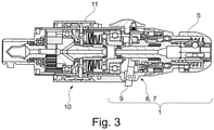
- the lever 9 is but pivotally mounted in the axial direction of the tool holder, as in the 3 is shown.
- a lever extension protruding into the interior of the housing is coupled to the ratchet output element in such a way that it can be displaced in the axial direction by pivoting the lever 9 .
- the ratchet output element has a drive in the form of a radial projection which acts directly or indirectly on the intermediate/selector component of the ratchet in order to drive it, if necessary, according to the axial movement of the ratchet output element.
- the intermediate/selection component of the ratchet is taken into an axial position in which it meshes with one of the two torque transmission elements can come.
- the ratchet function is activated.
- a separating clutch is implemented as it were.
- a torque limiting device 10 is also present between the manual ratchet, in particular between the ratchet output element and the drive-side clutch 3 . This can be set manually Can be unlocked and locked, e.g. via a rotary handle.
- the turning handle is provided with the reference number 11 .
Description
Die Erfindung betrifft einen Werkzeugaufnahmeaufsatz für eine medizinische, motorisch angetriebene Werkzeugmaschine wie beispielsweise chirurgische Bohrmaschine, die auch als chirurgischer Schraubendreher bezeichnet werden kann oder eingesetzt werden kann, mit einer antriebseitigen Kupplung zum Anbringen an einem (elektro-) motorisch Drehmoment bereitstellenden Antriebsaggregat/Motor, wie einer Antriebsmaschine mit einem Elektromotor und mit einer abtriebsseitigen Kupplung/Werkzeugaufnahmefutter zum Aufnehmen eines Werkzeugs, wie eines Schraubendrehers, eines Bohrers oder dergleichen Drehwerkzeuge.The invention relates to a tool holder attachment for a medical, motor-driven machine tool such as a surgical drill, which can also be referred to as a surgical screwdriver or can be used, with a drive-side coupling for attachment to a (electric) motor-driven torque-providing drive unit/motor, such as a prime mover with an electric motor and with an output-side clutch/tool receiving chuck for receiving a tool, such as a screwdriver, a drill or similar turning tools.
In der Medizintechnik, insbesondere in der Chirurgie, werden bei bestimmten chirurgischen Eingriffen Knochenschrauben gesetzt, bspw. sogenannte Pedikelschrauben, welche in der Wirbelsäulenchirurgie Verwendung finden. Dazu muss erst ein Bohrvorgang durchgeführt werden, um danach in das in den Wirbelkörper gebohrte Loch jeweils eine Schraube setzen zu können. Leider sind die zu behandelnden Knochen/Wirbel immer unterschiedlich spröde. Man bedarf daher eines gewissen Feingefühls, um die Bohrung sauber zu setzen und die Schraube zerstörungsfrei/d.h. ohne Beschädigung des Wirbelkörpers einzubringen. Allerdings sind besonders die letzte Phase des Bohrvorganges und die letzte Phase des Schraubvorganges kritisch. Bis dahin bedarf es viel Drehbewegung, um das Bohrloch zu kreieren und die Schraube tief genug einzubringen, sodass das Risiko eines Ausreißens des Wirbelknochens oder Überdrehens der Schraube insbesondere in der jeweiligen Endphase des Bohr- und Schraubvorgangs ansteigt.In medical technology, in particular in surgery, bone screws are used in certain surgical procedures, for example so-called pedicle screws, which are used in spinal column surgery. To do this, a drilling process must first be carried out in order to then be able to place a screw in the hole drilled in the vertebral body. Unfortunately, the bones/vertebrae to be treated are always brittle to varying degrees. A certain degree of sensitivity is therefore required in order to place the bore cleanly and to screw the screw non-destructively/i.e. inserted without damaging the vertebral body. However, the last phase of the drilling process and the last phase of the screwing process are particularly critical. Until then, a lot of turning movement is required to create the drill hole and to insert the screw deep enough, so that the risk of tearing out the vertebral bone or over-tightening of the screw increases, especially in the respective final phase of the drilling and screwing process.
Ein manuelles Eindrehen von chirurgischen Schrauben führt jedoch durch die repetitive Bewegung zu einer schnellen Ermüdung der Hand- und Armmuskulatur des Chirurgen. Das kann dann zu einem negativen Operationsergebnis führen und auch langfristige gesundheitliche Beschwerden bei den Ärzten hervorrufen.However, manually screwing in surgical screws leads to rapid fatigue of the surgeon's hand and arm muscles due to the repetitive movement. This can then lead to a negative surgical result and also cause long-term health problems for the doctors.
Es ist daher schon immer wünschenswert, ein motorisches Antriebsaggregat (elektrischer, hydraulischer oder pneumatischer Motor) zu nutzen, um Drehmoment bereit zu stellen. Dabei werden häufig elektromotorische Antriebsaggregate verwendet, also Antriebsmaschinen mit einem Elektromotor, die entweder batterie- / akkumulatorabhängig mit Energie versorgt werden, oder aber über ein Kabel auf eine externe Stromversorgung zugreifen.It has therefore always been desirable to use a motorized drive unit (electric, hydraulic or pneumatic motor) to provide torque. Electromotive drive units are often used here, i.e. driving machines with an electric motor, which are either supplied with energy depending on the battery / accumulator, or access an external power supply via a cable.
Es sind bereits sogenannte Spickdrahtfutter bekannt, die Aufsätze für chirurgische Bohrmaschinen sind, welche einen Hebel zur Erfüllung einer speziellen Funktion verwenden. Durch die Maschine wird ein Spickdraht geführt. Wird der Hebel gezogen, wird der Draht in der Maschine geklemmt, sodass er durch die Antriebsmaschine in eine Rotationsbewegung versetzt werden kann. Dadurch kann der Draht in ein Gewebe eingedreht werden. Beim Loslassen des Hebels kann der Draht wieder in der Maschine axial und rotatorisch frei bewegt werden. Dieses Prinzip wird auch in anderen medizinischen Einrichtungen weiter verfolgt.So-called wire chucks are already known, which are attachments for surgical drills that use a lever to perform a specific function. A wire is fed through the machine. If the lever is pulled, the wire is clamped in the machine so that it can be rotated by the drive machine. This allows the wire to be twisted into a fabric. When the lever is released, the wire can be freely moved axially and rotationally again in the machine. This principle is also followed in other medical institutions.
Benachbarter Stand der Technik ist bspw. aus der
Aus dem Stand der Technik ist etwa eine elektrische, kabelgebundene Schraubpistole bekannt, nämlich aus der
Die Ratsche ist elektrisch ausgestaltet/aktivierbar, was dazu führt, dass, um die Blockierung der Ratsche zu gewährleisten, ein solch hoher Strom in der Maschine fließt, dass eine starke Hitzeentwicklung zu beklagen ist. Auch fehlt ein akustisches Feedback. Ein, beispielsweise für das Durchführen des Bohrens in der letzten Bohrphase vorgenommenes manuelles Ratschen, oder ein während eines Gewindeeinschneidens verwendetes mechanisches Ratschen, bspw. wie es auch in der letzten Phase des Schraubens eingesetzt ist, ist hier nicht vorhanden. Durch die Kabelgebundenheit wird auch die Reichweite/Bewegungsfreiheit stark eingeschränkt. Ferner ist bei diesem System zu beklagen, dass ein abgeschlossenes System vorgestellt wird und ein versehentliches Betätigen des Gasdrückers während des manuellen Eindrehens zu einem plötzlichen Eindringen der Schraube führt oder zu einem plötzlichen Weiterbohren führt. Dies ist jedoch im Patienteneinsatz verheerend. Auch sind von anderen Herstellern Schraubenaufsätze bekannt, bspw. die "Synthes Bohrpistole 510.01". Auf diese Bohrpistole kann ein Aufsatz aufgesetzt werden, der die Ausgangsdrehzahl der Bohrpistole auf ca. 300 U/min untersetzt. Zur Verwendung ist dabei zusätzlich das Aufsetzen eines Drehmomentbegrenzers auf diesen Schraubenaufsatz vorgeschrieben. Leider sind solche Drehmomentbegrenzer nicht verstellbar und nur in vordefinierten Werten von 0,4 Nm, 0,8 Nm, 1,5 Nm und 4 Nm leicht erhältlich. Ferner ist dieses System nicht zum manuellen Eindrehen und Anziehen von Schrauben verwendbar. Ein Werkzeugwechsel ist daher immer notwendig. Auch zeigt sich in der Praxis die Drehmomentbegrenzung als unflexibel. Auch ein manuelles Eindrehen einer Schraube mit einer mechanischen Ratsche, bspw. mittels eines Schraubendrehers mit integrierter Ratsche, ist nicht zielführend, obwohl hier der Vorteil des Vermeidens des Umgreifens während des Eindrehvorganges vorliegt. Leider ist trotz Ratscheneinsatz immer noch eine solch repetitive Bewegung notwendig, die immer noch zur Ermüdung der Muskulatur führt, also auch das Operationsergebnis unmittelbar negativ beeinflussen kann. Auch die gesundheitlichen Beschwerden der Ärzte werden nicht vermieden.The ratchet is designed/can be activated electrically, which means that, in order to ensure that the ratchet is blocked, such a high current flows in the machine that a lot of heat is generated. There is also no acoustic feedback. A manual ratchet, for example for carrying out the drilling in the last drilling phase, or a mechanical ratchet used during thread cutting, for example as it is also used in the last phase of screwing, is not present here. Due to the cable connection, the range/freedom of movement is also severely restricted. Furthermore, this system has the disadvantage that a closed system is presented and accidental actuation of the gas trigger during manual screwing leads to sudden penetration of the screw or leads to sudden further drilling. However, this is devastating in patient use. Screw attachments are also known from other manufacturers, for example the "Synthes drill gun 510.01". An attachment can be attached to this drill gun, which reduces the output speed of the drill gun to approx. 300 rpm. A torque limiter must also be placed on this screw attachment for use. Unfortunately, such torque limiters are not adjustable and are only readily available in predefined values of 0.4 Nm, 0.8 Nm, 1.5 Nm and 4 Nm. Furthermore, this system cannot be used for manually screwing in and tightening screws. A tool change is therefore always necessary. In practice, the torque limitation has also proven to be inflexible. Manually screwing in a screw with a mechanical ratchet, e.g. using a screwdriver with an integrated ratchet, is also not expedient, although the advantage of avoiding gripping around during the screwing-in process is here. Unfortunately, despite the use of a ratchet, such a repetitive movement is still necessary, which still leads to fatigue of the muscles, which also affects the result of the operation can have an immediate negative impact. Even the health complaints of the doctors are not avoided.
Ferner ist bei den unterschiedlichen Systemen auch zu beklagen, dass sie entweder nur für Plattenverschraubungen einsetzbar sind oder nur bei Polyaxialschrauben. Polyaxialschrauben sind dabei bspw. solche Schrauben, die einen sphärischen Schraubenkopf aufweisen, der von einem Gehäuse umschlossen ist, derart, dass das Gehäuse frei zur Längsachse der Schraube verstellbar ist. Insbesondere Pedikelschrauben werden so ausgebildet.Furthermore, the fact that the different systems can only be used for screwing plates or only for polyaxial screws is to be lamented. Polyaxial screws are, for example, screws that have a spherical screw head that is surrounded by a housing such that the housing can be freely adjusted relative to the longitudinal axis of the screw. Pedicle screws in particular are designed in this way.
Es ist daher die Aufgabe der vorliegenden Erfindung, ein sowohl bei Pedikelschrauben/Polyaxialschrauben als auch bei Plattenverschraubungen einsetzbaren Werkzeugaufnahmeaufsatz zur Verfügung zu stellen, der die vorstehend beschriebenen Nachteile beseitigt oder diese zumindest mildert. Insbesondere soll auch eine Reduktion der körperlichen Belastung des Anwenders (Chirurgen) beim Einbringen von Schrauben erreicht werden. Ferner soll insbesondere die Erfindung dem Anwender (Chirurgen) ermöglichen, dass ein sicheres maschinelles Eindrehen erfolgt. Auch soll die Einstellung der Motordrehzahl so wählbar sein, dass der Anwender die Wunschdrehzahl präzise einstellen kann.It is therefore the object of the present invention to provide a tool holder attachment that can be used both for pedicle screws/polyaxial screws and for screwed plates, which eliminates the disadvantages described above or at least mitigates them. In particular, a reduction in the physical strain on the user (surgeon) when inserting screws should also be achieved. Furthermore, the invention should in particular enable the user (surgeon) to screw in safely by machine. The setting of the engine speed should also be selectable in such a way that the user can precisely set the desired speed.
Dies Aufgabe wird durch eine Werkzeugaufnahme mit den Merkmalen des Anspruchs 1 und durch eine Bohrmaschine mit den Merkmalen des Anspruchs 9 erzielt.This object is achieved by a tool holder with the features of
Der Grundgedanke der vorliegenden Erfindung beruht darauf, dass zwischen den beiden Kupplungen zum Anschluss eines Motors an der einen Eingangskupplung und zum Aufnehmen/Anschließen eines Werkzeugs an der anderen Ausgangskupplung eine manuell betätigbare / handkraftbetätigbare Antriebseinheit in Form einer Ratsche eingebunden ist, die mittels der Ratschenhandhabe/manuelle Betätigungseinrichtung der Ratsche selbst in eine erste Betriebsposition bringbar ist, in welcher das Drehmoment von der Eingangskupplung unter Umgehung der Ratschenfunktion auf die Ausgangskupplung übertragen wird und in eine zweite Betriebsposition bringbar ist, in welcher die beiden Kupplungen Drehmoment-getrennt sind und stattdessen ein über die Ratschenfunktion von der Ratschenhandhabe/manuelle Betätigungseinrichtung eingetragenes manuelles Drehmoment auf die Ausgangskupplung übertragen wird. Statt einer elektromotorischen Drehmomentweitergabe kann dann eine feiner justierbare manuelle Drehmomentweitergabe bewirkt werden. Dies kann geschehen, ohne dass ein Werkzeugwechsel durchgeführt werden muss und ohne dass die Maschine selbst separat zu der Ratsche in irgendeiner Weise betätigt werden muss. D.h. die vorstehend genannten Betriebspositionen sind ausschließlich durch Ratscheninterne Funktionen und Mittel (Ratschenhandhabe) einstellbar und nicht durch miteinander kommunizierende Funktionen der Ratsche und der Maschine. Somit ist gewährleistet, dass die beiden genannten Betriebspositionen eingestellt und auch gehalten werden können unabhängig davon, in welcher Weise die Maschine betätigt wird, etwa Betätigen des Motors, Aufdrücken des Werkzeugs auf den zu bohrenden Knochen/einzuschraubenden Schraube über die Maschine/den Maschinenhaltegriff, etc.. Auch ist ein somit sicherer Betrieb möglich. Schädigungen des Patienten oder des Arztes werden verhindert. Ein präziser Einsatz wird möglich.The basic idea of the present invention is that between the two couplings for connecting a motor to one input coupling and for receiving/connecting a tool to the other output coupling, a manually operable/hand power operable drive unit in the form of a ratchet is integrated, which can be operated by means of the ratchet handle/ manual actuating device of the ratchet itself can be brought into a first operating position, in which the torque is transmitted from the input clutch to the output clutch, bypassing the ratchet function, and can be brought into a second operating position, in which the two clutches are torque-separated and instead a via the Ratchet function from the ratchet handle / manual actuator entered manual torque is transmitted to the output clutch. Instead of an electromotive torque transfer, a more finely adjustable manual torque transfer can then be effected. This can be done without a tool change having to be performed and without the Machine itself must be operated separately from the ratchet in some way. This means that the above-mentioned operating positions can only be set by ratchet-internal functions and means (ratchet handle) and not by functions of the ratchet and the machine that communicate with one another. This ensures that the two operating positions mentioned can be set and maintained regardless of how the machine is operated, such as operating the motor, pressing the tool onto the bone to be drilled/screw to be screwed in via the machine/the machine handle, etc .. Safe operation is also possible. Damage to the patient or the doctor is prevented. Precise use becomes possible.
Im Konkreten kann es konstruktiv vorgesehen sein, die Ratsche mit zwei Drehmoment-Übertragungselementen (Hülsen) auszubilden, die jeweils eine gegenläufig wirkende Verzahnung tragen und je nach manueller Auswahl wechselweise in Funktion geschaltet werden können, um so eine rechts- oder linkswirkende Drehmomentübertragung von einem manuellen Eingangsbauteil etwa Ratschengehäuse auf ein Ratschen-Ausgangselement wie Abtriebshülse zu übertragen. Zwischen dem Ratschen-Ausgangselement und den beiden Drehmoment-Übertragungselementen ist eine Art Auswahlbauteil wie Wahlscheibe/-hülse angeordnet, das manuell so verstellt werden kann, dass es mit jeweils einem der Drehmoment-Übertragungselemente in Wirkeingriff kommt. Des Weiteren kann das Auswahlbauteil über das Ratschen-Ausgangselement bei dessen Betätigung mittels der Ratschen-Handhabe in eine Ratschen-Außerfunktionsposition verstellt werden, in welcher die Ratsche kein manuell eingebrachtes Drehmoment auf das Ratschen-Ausgangselement mehr übertragen kann, gleichzeitig aber das Ratschen-Ausgangselement in dieser Betätigungsposition die beiden Kupplungen unmittelbar drehmoment-verbindet.In concrete terms, it can be constructively provided to form the ratchet with two torque transmission elements (sleeves), each of which carries teeth acting in opposite directions and can be switched into function alternately depending on the manual selection, in order to achieve right-hand or left-hand torque transmission from a manual To transfer input component such as ratchet housing on a ratchet output element such as output sleeve. Between the ratchet output element and the two torque transmission elements there is a type of selection component such as a dial/sleeve that can be manually adjusted in such a way that it comes into operative engagement with one of the torque transmission elements at a time. Furthermore, the selection component can be adjusted via the ratchet output element when it is actuated by means of the ratchet handle into a ratchet non-functional position in which the ratchet can no longer transmit any manually applied torque to the ratchet output element, but at the same time the ratchet output element can this operating position directly torque-connects the two clutches.
Beispielsweise ist das Ratschen-Ausgangselement eine Hülse, welche eine Abtriebswelle der Werkzeugaufnahme axialverschiebbar aber drehfest umgreift und eine Verzahnung wie z.B. Stirnverzahnung hat, die in Abhängigkeit der Axialstellung des Ratschen-Ausgangselements bezüglich der Abtriebswelle der Werkzeugaufnahme mit einem direkten/indirekten Abtriebselement der Eingangskupplung in Eingriff bringbar ist. Ferner hat das Ratschen-Ausgangselement eine Art Mitnahme wie z.B. Mitnahmestift oder Vorsprung, die auf das vorstehend genannte Auswahlbauteil der Ratsche wirkt und dieses bei einer Verstellung des Ratschen-Ausgangselements in dessen Ratschen-Außerfunktionsposition in eine Position mitnimmt, in der ein Wirkeingriff zwischen dem Auswahlbauteil und den zwei Drehmoment-Übertragungselementen der Ratsche ausgeschlossen ist. In diesem Fall ist eine Drehmomentübertragung vom Motor auf die Ausgangskupplung ermöglicht, die Ratschenfunktion aber außer Kraft gesetzt. Wird hingegen das Ratschen-Ausgangselements in eine Position verstellt, in welcher kein direkter Wirkeingriff mit dem direkten/indirekten Abtriebselement der Eingangskupplung besteht, wird das Auswahlbauteil in eine Position, z.B. federelastisch gedrängt in der es wahlweise mit einem der zwei Drehmoment-Übertragungselemente in Wirkeingriff bringbar ist. In diesem Fall ist eine Drehmomentübertragung vom Motor auf die Ausgangskupplung unterbrochen, die Ratschenfunktion aber in Kraft gesetzt.For example, the ratchet output element is a sleeve which encloses an output shaft of the tool holder in an axially displaceable but non-rotatable manner and has teeth such as spur teeth which, depending on the axial position of the ratchet output element with respect to the output shaft of the tool holder, engage with a direct/indirect output element of the input clutch is bringable. Furthermore, the ratchet output element has a kind of driving such as driving pin or protrusion, which is on the above-mentioned selection component Ratchet acts and takes it with an adjustment of the ratchet output element in its ratchet non-functional position in a position in which an operative engagement between the selection component and the two torque transmission elements of the ratchet is excluded. In this case, torque transmission from the engine to the output clutch is enabled, but the ratchet function is disabled. If, on the other hand, the ratchet output element is adjusted to a position in which there is no direct operative engagement with the direct/indirect output element of the input clutch, the selection component is pushed into a position, e.g. resiliently, in which it can be brought into operative engagement with one of the two torque transmission elements is. In this case, torque transmission from the engine to the output clutch is interrupted, but the ratchet function is activated.
Um die Handhabung der Ratsche zu vereinfachen, kann die Handhabe beispielsweise ein Hebel sein, der am Gehäuse der Ratsche gelagert ist, um dieses um die Abtriebswelle der Werkzeugaufnahme zu drehen und so ein manuelles Drehmoment in die Ratsche einzutragen. Gleichzeitig kann der Hebel in Längsrichtung der Abtriebswelle der Werkzeugaufnahme verschwenkbar am Ratschengehäuse gelagert sein und an seinem in das Ratscheninnere vorragenden Ende auf das Ratschen-Ausgangselement einwirken, um dieses axial zu bewegen und so die beiden vorstehend genannten Positionen für ein außer/in Kraft setzen der Ratschenfunktion einzustellen.In order to simplify the handling of the ratchet, the handle can be a lever, for example, which is mounted on the housing of the ratchet in order to rotate it about the output shaft of the tool holder and thus enter a manual torque into the ratchet. At the same time, the lever can be pivoted on the ratchet housing in the longitudinal direction of the output shaft of the tool holder and can act on the ratchet output element at its end protruding into the interior of the ratchet in order to move it axially and thus set the two above-mentioned positions for a disabling/enabling of the to set the ratchet function.
In diesem Fall muss nur die eine, Ratschen-eigene Handhabe betätigt werden, um die beiden Positionen einzustellen und auch ein manuelles Drehmoment in die Ratsche einzutragen.In this case, only the ratchet's own handle has to be operated in order to set the two positions and also to enter a manual torque into the ratchet.
Vorteilhafte Ausführungsformen sind auch in den Unteransprüchen beansprucht und werden nachfolgend näher erläutert.Advantageous embodiments are also claimed in the dependent claims and are explained in more detail below.
So ist es von Vorteil, wenn die zum Drehmoment bereitstellen per Handkraft eingerichtete Antriebseinheit (Gehäuse) mit einer Ratscheinheit / Ratscheinrichtung oder einer Knarre (innerhalb des Gehäuses) verbunden ist oder mit ihr integriert ist. Eine umlaufende Drehbewegung innerhalb eines nur begrenzten Arbeitsraumes, z.B. zum Lösen oder Festziehen von Schraubverbindungen, wird dann effizient ermöglicht. Dazu kann eine Zahnung im Inneren der Ratscheinheit / Ratscheinrichtung oder Knarre eingesetzt werden, bspw. einen Drehwinkel von wenigstens 10° bis 15° erfordernd, um eine Drehung eines Abtriebselements zu erreichen. Es können aber auch Feinzahnratschen eingesetzt werden, so dass bereits ein Drehwinkel von rund 5° genügt, um eine Bewegung der Schraube zu zeitigen.It is therefore advantageous if the drive unit (housing) set up to provide torque by hand is connected to a ratchet unit/ratcheting device or a ratchet (within the housing) or is integrated with it. A circular rotary movement within a limited working space, eg for loosening or tightening screw connections, is then efficiently made possible. For this purpose, teeth can be used inside the ratchet unit/ratchet device or ratchet, for example requiring a rotation angle of at least 10° to 15° in order to to achieve rotation of an output element. However, fine-tooth ratchets can also be used, so that a rotation angle of around 5° is sufficient to cause the screw to move.
Es ist auch von Vorteil, wenn die Ratsche oder Knarre der manuellen Antriebseinheit (Ratschen-Eingangselement/Ratschengehäuse) nachgeschaltet ist, d.h. zwischen der manuellen Antriebseinheit und der abtriebsseitigen Kupplung (Ausgangskupplung) eingesetzt ist. Auf diese Weise kann ein effizientes Funktionieren erreicht werden.It is also advantageous if the ratchet or ratchet is located downstream of the manual drive unit (ratchet input element/ratchet housing), i.e. inserted between the manual drive unit and the output-side clutch (output clutch). In this way, efficient functioning can be achieved.
Um eine akustische Rückkopplung zu erleichtern, ist es von Vorteil, wenn die Ratscheinheit / Ratscheinrichtung als mechanische Ratsche ausgestaltet ist. Zusätzlich ist es möglich, über eine Richtungswahlbedieneinheit zwischen einem Rechtslauf und einem Linkslauf hin- und her zu schalten. Auf diese Weise können Schaltstellungen zum Einschrauben oder stattdessen zum Ausschrauben vorgehalten werden.In order to facilitate acoustic feedback, it is advantageous if the ratchet unit/ratchet device is designed as a mechanical ratchet. In addition, it is possible to switch back and forth between clockwise and counterclockwise rotation via a direction selection control unit. In this way, switching positions can be reserved for screwing in or instead for unscrewing.
Um eine Fehlbedienung zu vermeiden, ist es von Vorteil, wenn die Richtungswahlbedieneinheit so eingebunden ist, dass eine Betätigung nur im elektrischen Betrieb möglich ist.In order to avoid incorrect operation, it is advantageous if the direction selection control unit is integrated in such a way that it can only be operated in electrical mode.
Auch ist es von Vorteil, wenn die manuelle Antriebseinheit mit dem händisch greifbaren Hebel verbunden ist. Der Hebel kann dann Z-, N- oder S-förmig ausgestaltet sein. Wenn eine Drehmomentbegrenzungseinrichtung eingebunden ist, kann verhindert werden, dass über ein Grenzdrehmoment hinaus gebohrt oder geschraubt wird. Die Sicherheit in der Bedienung wird erhöht.It is also advantageous if the manual drive unit is connected to the manually grippable lever. The lever can then be Z-, N- or S-shaped. If a torque limiting device is integrated, drilling or screwing beyond a limit torque can be prevented. Safety in operation is increased.
Ein vorteilhaftes Ausführungsbeispiel ist auch dadurch gekennzeichnet, dass die Drehmomentbegrenzungseinrichtung zwischen der antriebsseitigen Kupplung und der Ratscheinrichtung / Ratscheinheit angeordnet ist.An advantageous exemplary embodiment is also characterized in that the torque limiting device is arranged between the drive-side clutch and the ratchet device/ratchet unit.
Es ist zweckmäßig, wenn die manuelle Antriebseinheit mit einer Trennkupplung derart verbunden ist, dass im Fall einer Betätigung der manuellen Antriebseinheit eine motorische Drehmomentweitergabe an die abtriebsseitige Kupplung ausgeschlossen wird. Vorteilhaft ist es, die Trennkupplung zu jedem Zeitpunkt betätigen zu können. Ein fließender oder digitaler Wechsel zwischen dem elektrischen und manuellen Betriebsmodus wird dadurch ermöglicht.It is expedient if the manual drive unit is connected to a separating clutch in such a way that, when the manual drive unit is actuated, motor torque transmission to the output-side clutch is ruled out. It is advantageous to be able to actuate the separating clutch at any time. This enables a smooth or digital change between the electric and manual operating modes.
Hierbei ist es von Vorteil, wenn die Trennkupplung mit dem Hebel der manuellen Antriebseinheit derart verbunden ist, dass bei einem entsprechenden Betätigen des Hebels der Ratsche die Trennkupplung betätigt wird.It is advantageous here if the separating clutch is connected to the lever of the manual drive unit in such a way that the separating clutch is actuated when the lever of the ratchet is actuated accordingly.
Die Erfindung betrifft auch eine chirurgische Bohrmaschine bzw. einen chirurgischen Schraubendreher mit einem Elektromotor, der über die antriebsseitige Kupplung des erfindungsgemäßen Werkzeugaufnahmeaufsatzes zum Drehmomenteinleiten in diesen Aufsatz verbunden ist.The invention also relates to a surgical drill or a surgical screwdriver with an electric motor which is connected via the drive-side coupling of the tool holder attachment according to the invention for introducing torque into this attachment.
Mit anderen Worten betrifft die Erfindung also einen Werkzeugaufnahmeaufsatz, bei dem sich durch einen manuellen Betriebsmodus der Anwender zu jedem Zeitpunkt entscheiden kann, ohne das Werkzeug zu wechseln, die Schraube manuell einzudrehen. Er erhält dadurch ein direkteres Feedback über den Zustand des Knochens. Durch eine mechanische Ratsche mit umschaltbarem Links- und Rechtslauf, wird dieses manuelle Eindrehen komfortabler gemacht. Um ein versehentliches Umschalten während des Eindrehens zu verhindern, kann die Drehrichtung (Links- / Rechtslauf) nur im elektrischen Modus gewechselt werden.In other words, the invention thus relates to a tool holder attachment in which the user can decide at any time, without changing the tool, to screw in the screw manually using a manual operating mode. This gives him direct feedback on the condition of the bone. A mechanical ratchet with switchable left and right rotation makes this manual turning more comfortable. To prevent accidental switching while screwing in, the direction of rotation (left / right) can only be changed in electric mode.
Eine frei einstellbare Drehmomentbegrenzung, welche nur im elektrischen Modus wirksam ist, unterstützt den Anwender bei der Wahl des richtigen Zeitpunktes, ab dem er manuell eindrehen möchte. Sie kann zusätzlich als Sicherheitsfunktion verwendet werden. Durch die freie Einstellbarkeit ist eine flexible Anpassung in verschiedene Einsatzbereiche möglich. Ein versehentliches Verstellen wird durch einen Verriegelungsmechanismus verhindert.A freely adjustable torque limitation, which is only effective in electric mode, supports the user in choosing the right time from which he wants to screw in manually. It can also be used as a safety function. Due to the free adjustability, flexible adaptation to different areas of application is possible. A locking mechanism prevents accidental adjustment.
Es wird eine mechanische Umsetzung eines manuellen Antriebs auf einer chirurgischen Bohrmaschine ermöglicht. Genauer, wird eine Umsetzung eines manuellen Antriebs in einem Aufsatz für eine chirurgische Bohrmaschine erreicht. Eine zusätzliche Integration einer Ratschfunktion wird erreicht. Ein Wechsel der Drehrichtung der Ratschfunktion ist vorgesehen. Ein fließender oder digitaler Wechsel zwischen einem elektrischen und manuellen Betriebsmodus wird durch einen Hebel ermöglicht. Die zusätzliche Kombination mit einer frei einstellbaren Drehmomentbegrenzung, die rastet oder stufenlos sein kann, aber auch auf eine Nm-Skala verzichten kann, ist von Vorteil. Die Umsetzung dieser Funktion ist in einem einzigen Aufsatz möglich.A mechanical implementation of a manual drive on a surgical drilling machine is made possible. More specifically, implementation of a manual drive in an attachment for a surgical drill is achieved. An additional integration of a ratchet function is achieved. A change in the direction of rotation of the ratchet function is provided. A fluid or digital switch between an electric and manual mode of operation is made possible by a lever. The additional combination with a freely adjustable torque limitation, which can be latched or stepless, but can also do without a Nm scale, is an advantage. This function can be implemented in a single attachment.
Es wird ein elektrisches und manuelles Schraubeneindrehen ohne Werkzeugwechsel ermöglicht. Die körperliche Belastung des Chirurgen wird gesenkt. Die Bediensicherheit wird erhöht, da ein Betätigen eines "Gasdrückers" im manuellen Modus unkritisch ist. Die Ratsche im manuellen Modus erhöht den Komfort beim manuellen Eindrehen. Ein akustisches Feedback wird durch die Ratsche, die ein Ratsch-Geräusch hervorruft, ermöglicht. Die Sicherheit wird durch eine einstellbare Drehmomentbegrenzung erhöht.Electric and manual screw driving without changing tools is possible. The physical strain on the surgeon is reduced. Operating safety is increased, since pressing a "gas trigger" in manual mode is uncritical. The ratchet in manual mode increases comfort when screwing in manually. An acoustic feedback is made possible by the ratchet, which makes a rattling noise. Safety is increased by an adjustable torque limit.
Ein akustisches Feedback beim Durchrutschen der Drehmomentbegrenzung wird ebenfalls erzwungen. Mit einer passenden Kupplung ist der Werkzeugaufnahmeaufsatz an jeder Antriebsmaschine einsetzbar, und zwar rein mechanisch. Es wird keine Elektronik benötigt, welche Probleme bei der Sterilisierbarkeit haben könnte. Eine einfache Bedienung ist die Folge.An acoustic feedback when the torque limiter slips is also enforced. With a suitable coupling, the tool holder attachment can be used on any drive machine, purely mechanically. No electronics are required, which could cause problems with sterilization. The result is simple operation.
Das manuelle Eindrehen von Schrauben erfordert einen hohen Zeit- und Kraftaufwand. Gleichzeitig können Ärzte nicht rein maschinell eindrehen, da das taktile Feedback fehlt. Die Erfindung macht es ohne Werkzeugwechsel möglich, Schrauben nach Wahl manuell und maschinell einzudrehen. Zur Unterstützung kann zusätzlich ein Begrenzungsdrehmoment frei eingestellt werden.Screwing in screws manually requires a lot of time and effort. At the same time, doctors cannot screw in purely mechanically because there is no tactile feedback. The invention makes it possible to screw in screws of your choice manually and mechanically without changing tools. A limiting torque can also be freely set for support.
Der Aufsatz wird über die "Plug-and-Play"-Kopplung an der Antriebsmaschine angekoppelt. Am distalen Ende befindet sich eine weitere "Plug-and-Play"-Kupplung, die in der Lage ist, ein Schraubwerkzeug aufzunehmen. Durch Entriegeln und Verstellen des Drehgriffs kann das Ausrastdrehmoment bei elektrischem Antrieb eingestellt werden. Nach Einstellung des Drehmoments kann der Drehgriff verriegelt werden. Um den Anwender bei der Anwendung zu unterstützen, kann der Drehgriff gerastert sein.The attachment is coupled to the drive machine via the "Plug-and-Play" coupling. At the distal end is another "plug-and-play" coupling capable of accepting a wrenching tool. The disengagement torque for electric drives can be adjusted by unlocking and adjusting the twist grip. After setting the torque, the turning handle can be locked. In order to support the user in the application, the rotary handle can be detented.
Durch ein Ziehen des Hebels in Längsrichtung der Werkzeugaufnahmewelle, wie dies vorstehend bereits angedeutet wurde, kann der Anwender Schrauben manuell in den Knochen über die Ratsche eindrehen. Im Umsetzungsbeispiel wird der Abtrieb derart komplett vom elektrischen Antrieb (Motor) getrennt, was die Bediensicherheit zusätzlich erhöht. Bei Loslassen des Hebels wird die Verbindung mit dem elektrischen Antrieb wieder hergestellt. Der manuelle Antrieb ist als verstellbare Ratsche umgesetzt. Mit einem weiteren Bedienelement kann der Anwender zwischen Links- und Rechtslauf wechseln. Um ein versehentliches Verstellen zu verhindern, ist die Betätigung nur im elektrischen Betriebsmodus möglich. Bei der Gestaltung des Bedienelementes wird Wert auf eine intuitive Bedienung gelegt. Folglich entspricht dem Umsetzungsbeispiel die vordere Position des Bedienelementes dem Rechtslauf, also dem Eindringen einer Schraube.By pulling the lever in the longitudinal direction of the tool holder shaft, as already indicated above, the user can screw screws into the bone manually using the ratchet. In the implementation example, the output is completely separated from the electric drive (motor), which also increases operating safety. When the lever is released, the connection to the electric drive is restored. The manual drive is implemented as an adjustable ratchet. With another control element, the user can switch between left and right rotation. To prevent accidental adjustment, actuation is only possible in electrical operating mode. When designing the control element, emphasis is placed on intuitive operation. Consequently, in the implementation example, the front position of the control element corresponds to clockwise rotation, i.e. the penetration of a screw.
Die Erfindung wird nachfolgend mit Hilfe einer Zeichnung näher erläutert. Dabei ist ein erstes Ausführungsbeispiel dargestellt. Es zeigen:
- Fig. 1
- eine Seitenansicht eines erfindungsgemäßen Werkzeugaufnahmeaufsatzes,
- Fig. 2
- eine erfindungsgemäße chirurgische Bohrmaschine, die auch als chirurgischer Schraubendreher verwendet werden kann, mit einem erfindungsgemäß adaptierten Werkzeugaufnahmeaufsatz in einer Seitenansicht, und
- Fig. 3
- eine Längsschnittansicht durch eine erfindungsgemäße Bohrmaschine.
- 1
- a side view of a tool holder attachment according to the invention,
- 2
- a surgical drill according to the invention, which can also be used as a surgical screwdriver, with a tool holder attachment adapted according to the invention, in a side view, and
- 3
- a longitudinal sectional view through a drill according to the invention.
Die Figuren dienen nur dem Verständnis der Erfindung. Gleiche Elemente sind mit denselben Bezugszeichen versehen.The figures only serve to understand the invention. Identical elements are provided with the same reference symbols.
In
Zurückkommend auf
Während am proximalen Ende des Werkzeugaufnahmeaufsatzes 1 die antriebsseitige Kupplung 3 vorhanden ist, ist am distalen Ende eine abtriebsseitige Kupplung (Ausgangskupplung) 5 vorhanden.While the drive-
Zwischen den beiden Kupplungen 3 und 5, wobei auch die abtriebsseitige Kupplung 5 als "Plug-and-Play-Kupplung" ausgestaltet ist, ist eine eigene, separate manuell betätigbare, d.h. über Handkraft betätigbare Antriebseinheit 6 vorhanden. Die Antriebseinheit 6 ist mit einer Ratscheinrichtung / Ratscheinheit 7 verbunden / integriert, wobei die Ratscheinrichtung / Ratscheinheit 7 als manuelle Ratsche ausgebildet ist.Between the two
Im Konkreten besteht die Ratsche 7 gemäß der
Diese relative Axialposition lässt sich mittels eines manuell betätigbaren Schiebers einstellen. Der Schieber ist dabei mit einem der beiden Drehmoment-Übertragungselemente gekoppelt, um dieses axial zu verschieben. Dadurch wird das zumindest eine axial verschiebbare Drehmoment-Übertragungselement mit dem Zwischen-/Auswahlbauteil in oder außer Kämmeingriff gebracht. Das Zwischen-/Auswahlbauteil ist ebenfalls axialverschieblich gehalten und mittels einer Feder in Richtung hin zu den beiden Zwischen-/Auswahlbauteilen vorgespannt. Wird somit das eine Drehmoment-Übertragungselement mittels des Schiebers gegen das Zwischen-/Auswahlbauteil axial in Kämmeingriff gedrückt, wird dieses gegen die Federvorspannung axial verschoben, wodurch der Kämmeingriff mit dem anderen Drehmoment-Übertragungselement aufgehoben wird und umgekehrt.This relative axial position can be adjusted by means of a manually operable slide. The slide is coupled to one of the two torque transmission elements in order to move it axially. As a result, the at least one axially displaceable torque transmission element is brought into or out of mesh with the intermediate/selection component. The intermediate/selector component is also held in an axially displaceable manner and is biased by a spring in the direction of the two intermediate/selector components. If one torque transmission element is pressed axially into meshing engagement with the intermediate/selection component by means of the slide, this is axially displaced against the spring preload, whereby the meshing engagement with the other torque transmission element is canceled and vice versa.
Die Verzahnungen der beiden Drehmoment-Übertragungselemente wirken dabei gegenläufig zueinander, derart, dass sie einen Rechts- oder Links-Drehmoment übertragen können und in die jeweils andere Richtung einen Freilauf bewirken. Je nach ausgewähltem Drehmoment-Übertragungselement kann so ein Rechts- oder Linkswirkendes Drehmoment ausgehend von der manuellen Antriebseinheit 6 über die Ratsche übertragen werden. Das Zwischen-/Auswahlbauteil ist ferner axialverschieblich aber drehfest auf einem hülsenförmigen Ratschen-Ausgangselement gelagert, das wiederum drehfest aber axialverschieblich auf einer Welle der abtriebsseitigen Kupplung 5 gelagert ist.The teeth of the two torque transmission elements act in opposite directions to one another in such a way that they can transmit a right or left torque and cause freewheeling in the other direction. Depending on the selected torque transmission element, a right or left-acting torque can be transmitted from the manual drive unit 6 via the ratchet. The intermediate/selection component is also axially displaceable but non-rotatably mounted on a sleeve-shaped ratchet output element, which in turn is non-rotatably but axially displaceably mounted on a shaft of the clutch 5 on the driven side.
Das Ratschen-Ausgangselement hat vorzugsweise stirnseitig eine Verzahnung, über die das Ratschen-Ausgangselement in Abhängigkeit seiner Axialposition bezüglich der Welle der abtriebsseitigen Kupplung 5 mit einem Ausgangselement der eingangsseitigen Kupplung 3 in drehmoment-übertragenden Kämmeingriff kommen kann, um ein Drehmoment vom Motor auf die ausgangsseitige Kupplung 5 zu übertragen.The ratchet output element preferably has teeth on the front side, via which the ratchet output element, depending on its axial position with respect to the shaft of the output-
Die manuelle Antriebseinheit (Gehäuse) 6 wird über einen Hebel 9 aktiviert und angetrieben. Dafür ist der Hebel 9 nach Art einer Kurbel ausgebildet und an die Größe einer menschlichen Hand angepasst. D.h. der Hebel 9 ist im Gehäuse 6 derart gelagert, das das Gehäuse 6 über diesen um die Mittelachse der Werkzeugaufnahme gedreht und damit die Drehmoment-Übertragungselemente angetrieben werden können. Der Hebel 9 ist aber in Axialrichtung der Werkzeugaufnahme schwenkbar gelagert, wie dies in der
Das Ratschen-Ausgangselement hat eine Mitnahme in Form eines Radialvorsprungs, der direkt oder indirekt auf das Zwischen-/Auswahlbauteil der Ratsche einwirkt, um dieses entsprechend der Axialbewegung des Ratschen-Ausgangselements ggf. mitzunehmen.The ratchet output element has a drive in the form of a radial projection which acts directly or indirectly on the intermediate/selector component of the ratchet in order to drive it, if necessary, according to the axial movement of the ratchet output element.
Wird demnach das Ratschen-Ausgangselement über den Hebel 9 axial gegen das Ausgangselement der eingangsseitigen Kupplung 3 in drehmoment-übertragenden Kämmeingriff verschoben, wird das Zwischen-/Auswahlbauteil der Ratsche in eine Axialposition mitgenommen, in der es nicht mehr in Kämmeingriff mit einem der zwei Drehmoment-Übertragungselemente kommen kann. In diesem Fall wird zwar ein Drehmoment vom Motor auf die ausgangsseitige Kupplung 5 übertragen, die Ratschenfunktion wird aber außer Kraft gesetzt. Wird hingegen das Ratschen-Ausgangselement über den Hebel 9 axial vom Ausgangselement der eingangsseitigen Kupplung 3 weg verschoben (kein Kämmeingriff mehr), wird das Zwischen-/Auswahlbauteil der Ratsche in eine Axialposition mitgenommen, in der es in Kämmeingriff mit einem der zwei Drehmoment-Übertragungselemente kommen kann. In diesem Fall kann zwar kein Drehmoment vom Motor auf die ausgangsseitige Kupplung 5 übertragen werden, die Ratschenfunktion wird aber in Kraft gesetzt. Dadurch wird quasi eine Trennkupplung realisiert.Accordingly, when the ratchet output member is shifted axially via the
Auf diese Weise erhält der Hebel 9 zwei Funktionen, nämlich
- das in/außer Kraft setzen der Ratschenfunktion bei gleichzeitigem An-/Abkoppeln des Motors mit/von der abtriebsseitigen Kupplung 5 und
- das manuelle Betätigen der Ratsche.
- activating/deactivating the ratchet function while simultaneously coupling/decoupling the motor to/from the output-
side clutch 5 and - manually operating the ratchet.
Zwischen der manuellen Ratsche insbesondere zwischen dem Ratschen-Ausgangselement und der antriebsseitigen Kupplung 3 ist auch eine Drehmomentbegrenzungseinrichtung 10 vorhanden. Diese ist manuell einstellbar, entriegel- und verriegelbar, bspw. über einen Drehgriff. Der Drehgriff ist mit dem Bezugszeichen 11 versehen.A
In
- 11
- Werkzeugaufnahmeaufsatztool holder attachment
- 22
- chirurgische Bohrmaschinesurgical drill
- 33
- antriebsseitige Kupplungdrive side clutch
- 44
- Antriebsaggregatdrive unit
- 55
- abtriebsseitige Kupplungoutput side clutch
- 66
- manuelle Antriebseinheit / Gehäusemanual drive unit / housing
- 77
- Ratscheinrichtung / RatscheinheitRatchet device / ratchet unit
- 88th
- Richtungswahlbedieneinheitdirectional control panel
- 99
- Hebellever
- 1010
- Drehmomentbegrenzungseinrichtungtorque limiting device
- 1111
- Drehgriffrotary handle
- 1212
- Betätigungsknopfoperating button
Claims (9)
- A tool fitting attachment (1) for a surgical machine, preferably a drill (2), comprising a drive-side coupling (3) for mounting to a drive unit (4) which provides a torque by means of a motor, and comprising an output-side coupling (5) for receiving a tool, wherein between the two couplings (3, 5), a manually operated drive unit (6) is integrated in the form of a ratchet unit (7), characterized in that the ratchet unit (7) has a handle (9) by means of which the ratchet unit (7) can be brought into a first operating position, in which the torque is transmittable from the drive-side coupling (3) to the output-side coupling (5), bypassing the ratchet unit (7), and can be brought into a second operating position, in which the drive-side and output-side couplings (3, 5) are torque-separated and a manual torque entered via the ratchet unit (7) is transmittable to the output-side coupling (5).
- The tool fitting attachment (1) according to claim 1, characterized in that the drive unit (6) is configured to provide a torque by manual force and is integrated with the ratchet unit (7).
- The tool fitting attachment (1) according to claim 1 or 2, characterized in that the ratchet unit (7) is in the form of a mechanical ratchet and is changeable between a clockwise rotation and an anti-clockwise rotation via a direction selection control unit (8).
- The tool fitting attachment (1) according to one of claims 2 to 3, characterized in that the manual drive unit (6) is connected to the handle in the form of a manually graspable lever (9).
- The tool fitting attachment (1) according to one of the preceding claims, characterized in that a torque limiter (10) is integrated.
- The tool fitting attachment (1) according to claim 5, characterized in that the torque limiter (10) is arranged between the output-side coupling (5) and the ratchet unit (7).
- The tool fitting attachment (1) according to one of the claims 2 to 4, characterized in that it comprises a disconnect coupling, and that the manual drive unit (6) is connected to the disconnect coupling so that upon actuation of the manual drive unit (6), a motor-driven torque transmission to the output-side coupling (5) is rendered impossible.
- The tool fitting attachment (1) according to claim 7, characterized in that the disconnect coupling is connected to the handle (9) of the manual drive unit (6) so that upon actuation of the lever (9) the disconnect coupling is actuated.
- A surgical drill (2) comprising a tool fitting attachment (1) according to one of the preceding claims.
Applications Claiming Priority (3)
| Application Number | Priority Date | Filing Date | Title |
|---|---|---|---|
| DE102015111878.5A DE102015111878A1 (en) | 2015-07-22 | 2015-07-22 | Space-saving Rat unit with freewheel |
| DE102015111877.7A DE102015111877A1 (en) | 2015-07-22 | 2015-07-22 | Tool holder for surgical drill with additional manual drive unit and surgical drill |
| PCT/EP2016/065988 WO2017012877A2 (en) | 2015-07-22 | 2016-07-06 | Tool fitting attachment for a surgical drill with additional manual drive unit, and surgical drill |
Publications (2)
| Publication Number | Publication Date |
|---|---|
| EP3324859A2 EP3324859A2 (en) | 2018-05-30 |
| EP3324859B1 true EP3324859B1 (en) | 2022-03-23 |
Family
ID=56345163
Family Applications (1)
| Application Number | Title | Priority Date | Filing Date |
|---|---|---|---|
| EP16734715.2A Active EP3324859B1 (en) | 2015-07-22 | 2016-07-06 | Spindle for surgical drill with additional manual drive and surgical drill |
Country Status (7)
| Country | Link |
|---|---|
| US (1) | US10702284B2 (en) |
| EP (1) | EP3324859B1 (en) |
| JP (1) | JP2018520793A (en) |
| CN (1) | CN107847235B (en) |
| DE (1) | DE102015111877A1 (en) |
| ES (1) | ES2914199T3 (en) |
| WO (1) | WO2017012877A2 (en) |
Families Citing this family (9)
| Publication number | Priority date | Publication date | Assignee | Title |
|---|---|---|---|---|
| DE102015111877A1 (en) * | 2015-07-22 | 2017-01-26 | Aesculap Ag | Tool holder for surgical drill with additional manual drive unit and surgical drill |
| DE102015111878A1 (en) | 2015-07-22 | 2017-01-26 | Aesculap Ag | Space-saving Rat unit with freewheel |
| USD919088S1 (en) * | 2019-03-13 | 2021-05-11 | Laurent Fumex | Medical drill |
| CN110522493B (en) * | 2019-08-14 | 2022-05-03 | 蚌埠医学院第一附属医院 | Skull milling cutter for craniotomy |
| US11696810B2 (en) * | 2019-08-15 | 2023-07-11 | Verb Surgical Inc. | Engagement, homing, and control of robotics surgical instrument |
| US11723672B2 (en) * | 2020-03-18 | 2023-08-15 | Shukla Medical | Chuck assembly for a medical device |
| US11944502B2 (en) | 2020-04-10 | 2024-04-02 | Medartis Ag | Torque limiting ratcheting handle for medical instrument |
| GB202104353D0 (en) * | 2021-03-26 | 2021-05-12 | Depuy Ireland Ultd Co | Improvements in and relating to connections |
| CN114366272B (en) * | 2021-12-16 | 2023-10-13 | 芜湖锐进医疗设备有限公司 | Ratchet handle capable of being positively and negatively adjusted |
Citations (2)
| Publication number | Priority date | Publication date | Assignee | Title |
|---|---|---|---|---|
| DE19942292C2 (en) * | 1999-09-04 | 2001-09-27 | Daimler Chrysler Ag | Intermediate link for a handheld screwdriver shaft |
| DE102011088252B4 (en) * | 2011-12-12 | 2013-11-28 | Schünke GmbH | Ratchet attachment for driving screwing tools |
Family Cites Families (56)
| Publication number | Priority date | Publication date | Assignee | Title |
|---|---|---|---|---|
| US3120845A (en) | 1961-02-20 | 1964-02-11 | David B Horner | Self-powered surgical drill |
| DE1871193U (en) * | 1962-12-19 | 1963-04-25 | Ford Werke Ag | DEVICE FOR TIGHTENING BOLTS. |
| JPS4413999Y1 (en) * | 1965-06-28 | 1969-06-12 | ||
| DE3146494C2 (en) * | 1981-11-24 | 1986-10-30 | Black & Decker, Inc. (Eine Gesellschaft N.D.Ges.D. Staates Delaware), Newark, Del. | Power tool, in particular hand tool, with torque monitoring |
| JPH0624867U (en) * | 1992-08-04 | 1994-04-05 | イワブチ株式会社 | Screw tightening tool |
| GB9304540D0 (en) * | 1993-03-05 | 1993-04-21 | Black & Decker Inc | Power tool and mechanism |
| DE4342464A1 (en) * | 1993-12-13 | 1995-06-14 | Joerg R Bauer | Screwdriver for tight or loose screws or nuts |
| US5613585A (en) | 1995-05-02 | 1997-03-25 | Beere Precision Medical Instruments, Inc. | Ratcheting screwdriver |
| US5619891A (en) | 1995-11-06 | 1997-04-15 | Beere Precision Medical Instruments, Inc. | Ratcheting screwdriver |
| EP0803319B1 (en) | 1996-04-26 | 2003-02-19 | Nippei Toyama Corporation | Tool change device and tool change method |
| US5794715A (en) * | 1996-07-08 | 1998-08-18 | Linvatec Corporation | Rotary tool head |
| DE19730300A1 (en) | 1997-03-07 | 1998-09-17 | Engelbert Gmeilbauer | Ratchet unit for turning hexagonal nuts |
| DE29723472U1 (en) | 1997-03-07 | 1998-09-10 | Gmeilbauer Engelbert | Ratchet mechanism |
| US5741263A (en) | 1997-04-18 | 1998-04-21 | Midas Rex Pneumatic Tools, Inc. | Mutiple flat quick release coupling |
| DE29819294U1 (en) | 1998-10-29 | 1999-04-15 | Gmeilbauer Engelbert | Screwdriver with freewheel ratchet in ballpoint format |
| US6562055B2 (en) * | 2000-02-18 | 2003-05-13 | Stryker Corporation | Cutting attachment for a surgical handpiece designed to be selectively coupled to the handpiece |
| US7066940B2 (en) * | 2001-03-21 | 2006-06-27 | Medtronic, Inc. | Surgical instrument with rotary cutting member and quick release coupling arrangement |
| CN2507614Y (en) * | 2001-10-21 | 2002-08-28 | 易健生 | Multipurpose screwdriver with hand assistor lever device |
| US6658970B2 (en) | 2001-12-14 | 2003-12-09 | Hsuan-Sen Shiao | Ratchet screwdriver |
| US6817458B1 (en) | 2002-01-16 | 2004-11-16 | Michael T. Gauthier | Ratcheting mechanism |
| DE10311455B3 (en) | 2003-03-15 | 2004-09-16 | Aesculap Ag & Co. Kg | Coupling for a surgical rotary drive hand piece comprises a catch which slides against the action of a spring into a extended position using a tool |
| TWI290880B (en) | 2004-07-23 | 2007-12-11 | Hou-Fei Hu | High torque ratchet screwdriver |
| US7181997B1 (en) | 2005-01-18 | 2007-02-27 | Pilling Weck, Incorporated | Ratchet screwdriver and method of making same |
| US20060248987A1 (en) | 2005-05-05 | 2006-11-09 | Patrick White | Ratchet handle |
| US20070006692A1 (en) * | 2005-07-11 | 2007-01-11 | Phan Christopher U | Torque limiting device |
| US8021365B2 (en) * | 2005-07-11 | 2011-09-20 | Kyphon Sarl | Surgical device having interchangeable components and methods of use |
| CH698913B1 (en) * | 2006-05-26 | 2009-12-15 | Hader Sa | medical torque tool. |
| DE102006057283A1 (en) | 2006-12-05 | 2008-06-12 | Robert Bosch Gmbh | hand tool |
| DE102007048928A1 (en) | 2007-10-12 | 2009-04-16 | Daimler Ag | Spindle drive for driving e.g. door, of motor vehicle, has clutch arranged between electric motor and spindle, where clutch is arranged behind motor and before transmission and spindle that is driven by motor |
| US9078671B2 (en) * | 2008-04-17 | 2015-07-14 | Warsaw Orthopedic, Inc. | Surgical tool |
| EP2138273B1 (en) * | 2008-06-25 | 2012-02-15 | Robert Bosch GmbH | Rotary tool having a manual ratchet mechanism |
| US8597316B2 (en) | 2008-09-05 | 2013-12-03 | Stryker Corporation | Cutting accessory for use with a medical/surgical powered handpiece, the accessory having retention features that facilitate the fine or coarse adjustment of the extension of the accessory shaft |
| TW201109127A (en) * | 2009-09-15 | 2011-03-16 | Jin-Tan Huang | Torque adjuster |
| US8714056B2 (en) * | 2010-09-03 | 2014-05-06 | Greatbatch Ltd. | Torque limiting mechanism with lock bushing |
| US10413345B2 (en) * | 2010-11-12 | 2019-09-17 | David B. Plotkin | Universal bone screw screwdriver |
| US8801713B2 (en) | 2011-04-07 | 2014-08-12 | DePuy Synthes Products, LLC | Surgical drill instrument with motor and locking mechanism to receive an attachment and a cutting burr |
| US8786233B2 (en) | 2011-04-27 | 2014-07-22 | Medtronic Xomed, Inc. | Electric ratchet for a powered screwdriver |
| US8985593B1 (en) * | 2011-07-14 | 2015-03-24 | Bradshaw Medical, Inc. | Self-locking internal adapter for D-shaped orthopedic adjustment tools |
| WO2013020877A1 (en) * | 2011-08-05 | 2013-02-14 | Charité - Universitätsmedizin Berlin | Medical device |
| WO2013143563A1 (en) * | 2012-03-30 | 2013-10-03 | Stryker Trauma Ag | Torque-limiting assembly for a surgical powertool |
| JP6008319B2 (en) * | 2012-10-12 | 2016-10-19 | パナソニックIpマネジメント株式会社 | Impact rotary tool |
| CA2903436C (en) * | 2013-03-12 | 2017-08-01 | Eca Medical Instruments | Ratcheting torque wrench |
| US20140277203A1 (en) * | 2013-03-14 | 2014-09-18 | Ebi, Llc | Torque multiplier, limiter, and counter-torque combinations and methods |
| EP2826596A3 (en) * | 2013-07-19 | 2015-07-22 | Panasonic Intellectual Property Management Co., Ltd. | Impact rotation tool and impact rotation tool attachment |
| JP6380924B2 (en) * | 2014-01-06 | 2018-08-29 | パナソニックIpマネジメント株式会社 | Method of measuring moment of inertia of impact rotary tool and impact rotary tool using the measurement method |
| US9795395B2 (en) * | 2014-06-10 | 2017-10-24 | Medos International Sarl | Retro-cutting instrument with adjustable limit setting |
| US9936961B2 (en) * | 2014-09-26 | 2018-04-10 | DePuy Synthes Products, Inc. | Surgical tool with feedback |
| DE102015111877A1 (en) * | 2015-07-22 | 2017-01-26 | Aesculap Ag | Tool holder for surgical drill with additional manual drive unit and surgical drill |
| DE102015111878A1 (en) * | 2015-07-22 | 2017-01-26 | Aesculap Ag | Space-saving Rat unit with freewheel |
| US10213270B2 (en) * | 2015-12-02 | 2019-02-26 | Lomack Industrial Co. Ltd. | Small disposable torque limiting driving tool with rubber grip |
| US20170314711A1 (en) * | 2016-04-29 | 2017-11-02 | Diba Industries, Inc. | Tightening tool for torque-limited fittings and systems including the torque-limited fittings |
| US20180104801A1 (en) * | 2016-10-17 | 2018-04-19 | Bradshaw Medical, Inc. | Torque-limiting driver with embodied roller |
| US10874406B2 (en) | 2017-02-28 | 2020-12-29 | MFr Technologies, Inc. | Handheld surgical instrument |
| US10695073B2 (en) * | 2017-08-22 | 2020-06-30 | Arthrex, Inc. | Control system for retrograde drill medical device |
| US10779872B2 (en) * | 2017-11-02 | 2020-09-22 | Medos International Sarl | Bone anchor insertion instruments and methods |
| JP7398378B2 (en) | 2018-01-26 | 2023-12-14 | マコ サージカル コーポレーション | End effector and method for driving tools guided by a surgical robotic system |
-
2015
- 2015-07-22 DE DE102015111877.7A patent/DE102015111877A1/en not_active Withdrawn
-
2016
- 2016-07-06 JP JP2018502233A patent/JP2018520793A/en active Pending
- 2016-07-06 WO PCT/EP2016/065988 patent/WO2017012877A2/en active Application Filing
- 2016-07-06 US US15/744,960 patent/US10702284B2/en active Active
- 2016-07-06 CN CN201680043019.1A patent/CN107847235B/en active Active
- 2016-07-06 ES ES16734715T patent/ES2914199T3/en active Active
- 2016-07-06 EP EP16734715.2A patent/EP3324859B1/en active Active
Patent Citations (2)
| Publication number | Priority date | Publication date | Assignee | Title |
|---|---|---|---|---|
| DE19942292C2 (en) * | 1999-09-04 | 2001-09-27 | Daimler Chrysler Ag | Intermediate link for a handheld screwdriver shaft |
| DE102011088252B4 (en) * | 2011-12-12 | 2013-11-28 | Schünke GmbH | Ratchet attachment for driving screwing tools |
Also Published As
| Publication number | Publication date |
|---|---|
| WO2017012877A3 (en) | 2017-05-11 |
| EP3324859A2 (en) | 2018-05-30 |
| US20180206856A1 (en) | 2018-07-26 |
| ES2914199T3 (en) | 2022-06-08 |
| CN107847235B (en) | 2022-03-08 |
| DE102015111877A1 (en) | 2017-01-26 |
| CN107847235A (en) | 2018-03-27 |
| JP2018520793A (en) | 2018-08-02 |
| US10702284B2 (en) | 2020-07-07 |
| WO2017012877A2 (en) | 2017-01-26 |
Similar Documents
| Publication | Publication Date | Title |
|---|---|---|
| EP3324859B1 (en) | Spindle for surgical drill with additional manual drive and surgical drill | |
| EP1434523B1 (en) | Multifunctional instrument for use in microinvasive surgery | |
| EP3324860B1 (en) | Space-saving ratchet with freewheel | |
| EP0860148A2 (en) | Bayonet coupling for the releasable connection of two tubular-shaft instruments or two parts of an instrument | |
| EP2389879B1 (en) | Medical instrument with removable handle | |
| DE102014109200A1 (en) | Medical screwdriver, shaft for the medical screwdriver and method for introducing pedicle screws | |
| EP1952947B1 (en) | Hand-held power driven tool for drilling and/or screwing | |
| WO2017144172A1 (en) | Mounting for an instrument | |
| EP3777720A1 (en) | Medical drive unit of the hand held type with sensor device and kick-back control | |
| EP2489315A1 (en) | Medical instrument | |
| EP2910202B1 (en) | Instrument for carrying out medical procedures | |
| EP3372343B1 (en) | Assembly consisting of a torque-discharging support arm and a screwdriver | |
| EP3313622B1 (en) | Portable power tool | |
| CH697058A5 (en) | Chuck. | |
| DE102009054185B3 (en) | Wrench for use in e.g. drill installation system of tempering device, has tempering element i.e. induction element, for heating clamping nut, where tempering element is circular in shape and arranged coaxial to clamping axis of wrench | |
| DE102014103052A1 (en) | Screwing device with rotating tools | |
| DE102014104367A1 (en) | Drilling device and slip clutch for a drilling device | |
| US10874442B2 (en) | Multi-mode torque drivers employing inner surfaces compatible with pedicle screw guide wires, and related systems and methods | |
| DE102011050602B4 (en) | Chuck assembly of a medical hand drill or hand milling machine | |
| EP3005963B1 (en) | Electrical machine tool, in particular electric screw driver for use in surgery | |
| EP2702950A1 (en) | Medical tool system and handle and tool for a medical tool system | |
| EP3609653B1 (en) | Power screwdriver | |
| WO2024033228A1 (en) | Medical motor handpiece for 2-in-1 operation and medical manual instrument with 2-in-1 operation | |
| DE102016101822A1 (en) | Instrument for guiding a rod into an implant receptacle | |
| EP4321107A1 (en) | Medical motor hand piece with a detent and/or fixing unit |
Legal Events
| Date | Code | Title | Description |
|---|---|---|---|
| STAA | Information on the status of an ep patent application or granted ep patent |
Free format text: STATUS: THE INTERNATIONAL PUBLICATION HAS BEEN MADE |
|
| PUAI | Public reference made under article 153(3) epc to a published international application that has entered the european phase |
Free format text: ORIGINAL CODE: 0009012 |
|
| STAA | Information on the status of an ep patent application or granted ep patent |
Free format text: STATUS: REQUEST FOR EXAMINATION WAS MADE |
|
| 17P | Request for examination filed |
Effective date: 20180202 |
|
| AK | Designated contracting states |
Kind code of ref document: A2 Designated state(s): AL AT BE BG CH CY CZ DE DK EE ES FI FR GB GR HR HU IE IS IT LI LT LU LV MC MK MT NL NO PL PT RO RS SE SI SK SM TR |
|
| AX | Request for extension of the european patent |
Extension state: BA ME |
|
| DAV | Request for validation of the european patent (deleted) | ||
| DAX | Request for extension of the european patent (deleted) | ||
| GRAP | Despatch of communication of intention to grant a patent |
Free format text: ORIGINAL CODE: EPIDOSNIGR1 |
|
| STAA | Information on the status of an ep patent application or granted ep patent |
Free format text: STATUS: GRANT OF PATENT IS INTENDED |
|
| RIC1 | Information provided on ipc code assigned before grant |
Ipc: B25F 5/02 20060101ALI20210907BHEP Ipc: B25F 3/00 20060101ALI20210907BHEP Ipc: B25B 23/14 20060101ALI20210907BHEP Ipc: B25B 21/00 20060101ALI20210907BHEP Ipc: B25B 13/46 20060101ALI20210907BHEP Ipc: A61B 17/00 20060101ALI20210907BHEP Ipc: A61B 17/16 20060101AFI20210907BHEP |
|
| INTG | Intention to grant announced |
Effective date: 20211006 |
|
| GRAS | Grant fee paid |
Free format text: ORIGINAL CODE: EPIDOSNIGR3 |
|
| GRAA | (expected) grant |
Free format text: ORIGINAL CODE: 0009210 |
|
| STAA | Information on the status of an ep patent application or granted ep patent |
Free format text: STATUS: THE PATENT HAS BEEN GRANTED |
|
| AK | Designated contracting states |
Kind code of ref document: B1 Designated state(s): AL AT BE BG CH CY CZ DE DK EE ES FI FR GB GR HR HU IE IS IT LI LT LU LV MC MK MT NL NO PL PT RO RS SE SI SK SM TR |
|
| REG | Reference to a national code |
Ref country code: GB Ref legal event code: FG4D Free format text: NOT ENGLISH |
|
| REG | Reference to a national code |
Ref country code: CH Ref legal event code: EP |
|
| REG | Reference to a national code |
Ref country code: DE Ref legal event code: R096 Ref document number: 502016014672 Country of ref document: DE |
|
| REG | Reference to a national code |
Ref country code: IE Ref legal event code: FG4D Free format text: LANGUAGE OF EP DOCUMENT: GERMAN |
|
| REG | Reference to a national code |
Ref country code: AT Ref legal event code: REF Ref document number: 1476910 Country of ref document: AT Kind code of ref document: T Effective date: 20220415 |
|
| REG | Reference to a national code |
Ref country code: ES Ref legal event code: FG2A Ref document number: 2914199 Country of ref document: ES Kind code of ref document: T3 Effective date: 20220608 |
|
| REG | Reference to a national code |
Ref country code: LT Ref legal event code: MG9D |
|
| REG | Reference to a national code |
Ref country code: NL Ref legal event code: MP Effective date: 20220323 |
|
| PG25 | Lapsed in a contracting state [announced via postgrant information from national office to epo] |
Ref country code: SE Free format text: LAPSE BECAUSE OF FAILURE TO SUBMIT A TRANSLATION OF THE DESCRIPTION OR TO PAY THE FEE WITHIN THE PRESCRIBED TIME-LIMIT Effective date: 20220323 Ref country code: RS Free format text: LAPSE BECAUSE OF FAILURE TO SUBMIT A TRANSLATION OF THE DESCRIPTION OR TO PAY THE FEE WITHIN THE PRESCRIBED TIME-LIMIT Effective date: 20220323 Ref country code: NO Free format text: LAPSE BECAUSE OF FAILURE TO SUBMIT A TRANSLATION OF THE DESCRIPTION OR TO PAY THE FEE WITHIN THE PRESCRIBED TIME-LIMIT Effective date: 20220623 Ref country code: LT Free format text: LAPSE BECAUSE OF FAILURE TO SUBMIT A TRANSLATION OF THE DESCRIPTION OR TO PAY THE FEE WITHIN THE PRESCRIBED TIME-LIMIT Effective date: 20220323 Ref country code: HR Free format text: LAPSE BECAUSE OF FAILURE TO SUBMIT A TRANSLATION OF THE DESCRIPTION OR TO PAY THE FEE WITHIN THE PRESCRIBED TIME-LIMIT Effective date: 20220323 Ref country code: BG Free format text: LAPSE BECAUSE OF FAILURE TO SUBMIT A TRANSLATION OF THE DESCRIPTION OR TO PAY THE FEE WITHIN THE PRESCRIBED TIME-LIMIT Effective date: 20220623 |
|
| PG25 | Lapsed in a contracting state [announced via postgrant information from national office to epo] |
Ref country code: LV Free format text: LAPSE BECAUSE OF FAILURE TO SUBMIT A TRANSLATION OF THE DESCRIPTION OR TO PAY THE FEE WITHIN THE PRESCRIBED TIME-LIMIT Effective date: 20220323 Ref country code: GR Free format text: LAPSE BECAUSE OF FAILURE TO SUBMIT A TRANSLATION OF THE DESCRIPTION OR TO PAY THE FEE WITHIN THE PRESCRIBED TIME-LIMIT Effective date: 20220624 Ref country code: FI Free format text: LAPSE BECAUSE OF FAILURE TO SUBMIT A TRANSLATION OF THE DESCRIPTION OR TO PAY THE FEE WITHIN THE PRESCRIBED TIME-LIMIT Effective date: 20220323 |
|
| PG25 | Lapsed in a contracting state [announced via postgrant information from national office to epo] |
Ref country code: NL Free format text: LAPSE BECAUSE OF FAILURE TO SUBMIT A TRANSLATION OF THE DESCRIPTION OR TO PAY THE FEE WITHIN THE PRESCRIBED TIME-LIMIT Effective date: 20220323 |
|
| PG25 | Lapsed in a contracting state [announced via postgrant information from national office to epo] |
Ref country code: SM Free format text: LAPSE BECAUSE OF FAILURE TO SUBMIT A TRANSLATION OF THE DESCRIPTION OR TO PAY THE FEE WITHIN THE PRESCRIBED TIME-LIMIT Effective date: 20220323 Ref country code: SK Free format text: LAPSE BECAUSE OF FAILURE TO SUBMIT A TRANSLATION OF THE DESCRIPTION OR TO PAY THE FEE WITHIN THE PRESCRIBED TIME-LIMIT Effective date: 20220323 Ref country code: RO Free format text: LAPSE BECAUSE OF FAILURE TO SUBMIT A TRANSLATION OF THE DESCRIPTION OR TO PAY THE FEE WITHIN THE PRESCRIBED TIME-LIMIT Effective date: 20220323 Ref country code: PT Free format text: LAPSE BECAUSE OF FAILURE TO SUBMIT A TRANSLATION OF THE DESCRIPTION OR TO PAY THE FEE WITHIN THE PRESCRIBED TIME-LIMIT Effective date: 20220725 Ref country code: EE Free format text: LAPSE BECAUSE OF FAILURE TO SUBMIT A TRANSLATION OF THE DESCRIPTION OR TO PAY THE FEE WITHIN THE PRESCRIBED TIME-LIMIT Effective date: 20220323 Ref country code: CZ Free format text: LAPSE BECAUSE OF FAILURE TO SUBMIT A TRANSLATION OF THE DESCRIPTION OR TO PAY THE FEE WITHIN THE PRESCRIBED TIME-LIMIT Effective date: 20220323 |
|
| PG25 | Lapsed in a contracting state [announced via postgrant information from national office to epo] |
Ref country code: PL Free format text: LAPSE BECAUSE OF FAILURE TO SUBMIT A TRANSLATION OF THE DESCRIPTION OR TO PAY THE FEE WITHIN THE PRESCRIBED TIME-LIMIT Effective date: 20220323 Ref country code: IS Free format text: LAPSE BECAUSE OF FAILURE TO SUBMIT A TRANSLATION OF THE DESCRIPTION OR TO PAY THE FEE WITHIN THE PRESCRIBED TIME-LIMIT Effective date: 20220723 Ref country code: AL Free format text: LAPSE BECAUSE OF FAILURE TO SUBMIT A TRANSLATION OF THE DESCRIPTION OR TO PAY THE FEE WITHIN THE PRESCRIBED TIME-LIMIT Effective date: 20220323 |
|
| REG | Reference to a national code |
Ref country code: DE Ref legal event code: R097 Ref document number: 502016014672 Country of ref document: DE |
|
| PLBE | No opposition filed within time limit |
Free format text: ORIGINAL CODE: 0009261 |
|
| STAA | Information on the status of an ep patent application or granted ep patent |
Free format text: STATUS: NO OPPOSITION FILED WITHIN TIME LIMIT |
|
| PG25 | Lapsed in a contracting state [announced via postgrant information from national office to epo] |
Ref country code: DK Free format text: LAPSE BECAUSE OF FAILURE TO SUBMIT A TRANSLATION OF THE DESCRIPTION OR TO PAY THE FEE WITHIN THE PRESCRIBED TIME-LIMIT Effective date: 20220323 |
|
| PG25 | Lapsed in a contracting state [announced via postgrant information from national office to epo] |
Ref country code: MC Free format text: LAPSE BECAUSE OF FAILURE TO SUBMIT A TRANSLATION OF THE DESCRIPTION OR TO PAY THE FEE WITHIN THE PRESCRIBED TIME-LIMIT Effective date: 20220323 |
|
| REG | Reference to a national code |
Ref country code: CH Ref legal event code: PL |
|
| 26N | No opposition filed |
Effective date: 20230102 |
|
| REG | Reference to a national code |
Ref country code: BE Ref legal event code: MM Effective date: 20220731 |
|
| PG25 | Lapsed in a contracting state [announced via postgrant information from national office to epo] |
Ref country code: LU Free format text: LAPSE BECAUSE OF NON-PAYMENT OF DUE FEES Effective date: 20220706 Ref country code: LI Free format text: LAPSE BECAUSE OF NON-PAYMENT OF DUE FEES Effective date: 20220731 Ref country code: CH Free format text: LAPSE BECAUSE OF NON-PAYMENT OF DUE FEES Effective date: 20220731 |
|
| PG25 | Lapsed in a contracting state [announced via postgrant information from national office to epo] |
Ref country code: SI Free format text: LAPSE BECAUSE OF FAILURE TO SUBMIT A TRANSLATION OF THE DESCRIPTION OR TO PAY THE FEE WITHIN THE PRESCRIBED TIME-LIMIT Effective date: 20220323 Ref country code: BE Free format text: LAPSE BECAUSE OF NON-PAYMENT OF DUE FEES Effective date: 20220731 |
|
| PG25 | Lapsed in a contracting state [announced via postgrant information from national office to epo] |
Ref country code: IE Free format text: LAPSE BECAUSE OF NON-PAYMENT OF DUE FEES Effective date: 20220706 |
|
| P01 | Opt-out of the competence of the unified patent court (upc) registered |
Effective date: 20230807 |
|
| REG | Reference to a national code |
Ref country code: AT Ref legal event code: MM01 Ref document number: 1476910 Country of ref document: AT Kind code of ref document: T Effective date: 20220706 |
|
| PG25 | Lapsed in a contracting state [announced via postgrant information from national office to epo] |
Ref country code: AT Free format text: LAPSE BECAUSE OF NON-PAYMENT OF DUE FEES Effective date: 20220706 |
|
| PGFP | Annual fee paid to national office [announced via postgrant information from national office to epo] |
Ref country code: IT Payment date: 20230731 Year of fee payment: 8 Ref country code: GB Payment date: 20230724 Year of fee payment: 8 Ref country code: ES Payment date: 20230821 Year of fee payment: 8 |
|
| PGFP | Annual fee paid to national office [announced via postgrant information from national office to epo] |
Ref country code: FR Payment date: 20230724 Year of fee payment: 8 Ref country code: DE Payment date: 20230720 Year of fee payment: 8 |
|
| PG25 | Lapsed in a contracting state [announced via postgrant information from national office to epo] |
Ref country code: HU Free format text: LAPSE BECAUSE OF FAILURE TO SUBMIT A TRANSLATION OF THE DESCRIPTION OR TO PAY THE FEE WITHIN THE PRESCRIBED TIME-LIMIT; INVALID AB INITIO Effective date: 20160706 |