EP4321107A1 - Medical motor hand piece with a detent and/or fixing unit - Google Patents
Medical motor hand piece with a detent and/or fixing unit Download PDFInfo
- Publication number
- EP4321107A1 EP4321107A1 EP23189302.5A EP23189302A EP4321107A1 EP 4321107 A1 EP4321107 A1 EP 4321107A1 EP 23189302 A EP23189302 A EP 23189302A EP 4321107 A1 EP4321107 A1 EP 4321107A1
- Authority
- EP
- European Patent Office
- Prior art keywords
- section
- motor handpiece
- medical
- operating element
- locking
- Prior art date
- Legal status (The legal status is an assumption and is not a legal conclusion. Google has not performed a legal analysis and makes no representation as to the accuracy of the status listed.)
- Pending
Links
- 239000012636 effector Substances 0.000 claims abstract description 26
- 230000000694 effects Effects 0.000 claims abstract description 4
- 239000000853 adhesive Substances 0.000 claims description 6
- 230000001070 adhesive effect Effects 0.000 claims description 6
- 239000000835 fiber Substances 0.000 claims description 6
- 230000008878 coupling Effects 0.000 description 33
- 238000010168 coupling process Methods 0.000 description 33
- 238000005859 coupling reaction Methods 0.000 description 33
- 230000005540 biological transmission Effects 0.000 description 9
- 238000005096 rolling process Methods 0.000 description 9
- 230000007246 mechanism Effects 0.000 description 3
- 238000000034 method Methods 0.000 description 3
- 238000003801 milling Methods 0.000 description 3
- 230000004048 modification Effects 0.000 description 3
- 238000012986 modification Methods 0.000 description 3
- 229920001296 polysiloxane Polymers 0.000 description 3
- 230000036316 preload Effects 0.000 description 3
- 239000002245 particle Substances 0.000 description 2
- 230000002093 peripheral effect Effects 0.000 description 2
- 238000005498 polishing Methods 0.000 description 2
- 238000001356 surgical procedure Methods 0.000 description 2
- 230000001154 acute effect Effects 0.000 description 1
- 238000004026 adhesive bonding Methods 0.000 description 1
- 238000005452 bending Methods 0.000 description 1
- 210000000988 bone and bone Anatomy 0.000 description 1
- 210000000845 cartilage Anatomy 0.000 description 1
- 230000008859 change Effects 0.000 description 1
- 238000010276 construction Methods 0.000 description 1
- 238000009434 installation Methods 0.000 description 1
- 230000010354 integration Effects 0.000 description 1
- 238000002324 minimally invasive surgery Methods 0.000 description 1
- 230000007935 neutral effect Effects 0.000 description 1
- 239000011368 organic material Substances 0.000 description 1
- 230000000399 orthopedic effect Effects 0.000 description 1
- 230000008569 process Effects 0.000 description 1
- 238000000926 separation method Methods 0.000 description 1
- 230000007704 transition Effects 0.000 description 1
- 238000011282 treatment Methods 0.000 description 1
- 238000003466 welding Methods 0.000 description 1
Images


Classifications
-
- A—HUMAN NECESSITIES
- A61—MEDICAL OR VETERINARY SCIENCE; HYGIENE
- A61B—DIAGNOSIS; SURGERY; IDENTIFICATION
- A61B17/00—Surgical instruments, devices or methods, e.g. tourniquets
- A61B17/16—Bone cutting, breaking or removal means other than saws, e.g. Osteoclasts; Drills or chisels for bones; Trepans
- A61B17/1613—Component parts
- A61B17/1626—Control means; Display units
-
- A—HUMAN NECESSITIES
- A61—MEDICAL OR VETERINARY SCIENCE; HYGIENE
- A61B—DIAGNOSIS; SURGERY; IDENTIFICATION
- A61B17/00—Surgical instruments, devices or methods, e.g. tourniquets
- A61B17/16—Bone cutting, breaking or removal means other than saws, e.g. Osteoclasts; Drills or chisels for bones; Trepans
- A61B17/1613—Component parts
- A61B17/1622—Drill handpieces
-
- A—HUMAN NECESSITIES
- A61—MEDICAL OR VETERINARY SCIENCE; HYGIENE
- A61B—DIAGNOSIS; SURGERY; IDENTIFICATION
- A61B17/00—Surgical instruments, devices or methods, e.g. tourniquets
- A61B17/16—Bone cutting, breaking or removal means other than saws, e.g. Osteoclasts; Drills or chisels for bones; Trepans
- A61B17/1613—Component parts
- A61B17/1615—Drill bits, i.e. rotating tools extending from a handpiece to contact the worked material
- A61B17/1617—Drill bits, i.e. rotating tools extending from a handpiece to contact the worked material with mobile or detachable parts
-
- A—HUMAN NECESSITIES
- A61—MEDICAL OR VETERINARY SCIENCE; HYGIENE
- A61B—DIAGNOSIS; SURGERY; IDENTIFICATION
- A61B17/00—Surgical instruments, devices or methods, e.g. tourniquets
- A61B17/16—Bone cutting, breaking or removal means other than saws, e.g. Osteoclasts; Drills or chisels for bones; Trepans
- A61B17/1613—Component parts
- A61B17/162—Chucks or tool parts which are to be held in a chuck
-
- A—HUMAN NECESSITIES
- A61—MEDICAL OR VETERINARY SCIENCE; HYGIENE
- A61B—DIAGNOSIS; SURGERY; IDENTIFICATION
- A61B17/00—Surgical instruments, devices or methods, e.g. tourniquets
- A61B17/16—Bone cutting, breaking or removal means other than saws, e.g. Osteoclasts; Drills or chisels for bones; Trepans
- A61B17/1613—Component parts
- A61B17/1631—Special drive shafts, e.g. flexible shafts
-
- A—HUMAN NECESSITIES
- A61—MEDICAL OR VETERINARY SCIENCE; HYGIENE
- A61B—DIAGNOSIS; SURGERY; IDENTIFICATION
- A61B17/00—Surgical instruments, devices or methods, e.g. tourniquets
- A61B17/16—Bone cutting, breaking or removal means other than saws, e.g. Osteoclasts; Drills or chisels for bones; Trepans
- A61B2017/1602—Mills
Definitions
- the disclosure relates to a medical motor handpiece with a latching and/or stop unit and a medical hand instrument with the medical motor handpiece.
- tools/instruments and associated instrument handpieces/hand instruments are used, for example, for processing bones, cartilage in arthroscopic procedures, in spinal surgery and similar orthopedic/surgical treatments, as well as for processing organic material in neurosurgery.
- the tools/instruments have a handpiece/handle/handle section and possibly replaceable effectors, such as milling cutters, rotary knives, a polishing head or the like.
- the effector is mounted in a shaft of the tool/instrument at its distal end, possibly rotatably driven.
- a hydraulic, pneumatic or electric motor drive is provided as a tool drive, which is operatively connected to the tool head (effector) via a torque transmission train within the tool and/or the hand instrument or the handle section.
- the drives can be integrated in the tool and/or in the hand instrument or can be designed as external drive units that are coupled to the tool or the hand instrument via power supply lines or torque transmission lines.
- the actuation mechanism can be operated intuitively and safely by an operator, even without the operator taking his eyes off an engagement point on the effector, in order to increase patient safety. In other words, it is desirable that the operator can operate the operating mechanism blindly.
- Bendable shafts for medical hand instruments are well known and usually have a proximal and a bendable distal shaft section.
- the distal shaft section and the proximal shaft section each have an oblique end/an end face that is positioned relative to the respective shaft section axis.
- the bevels/inclined end sections/end faces each have essentially the same angle of attack. That is why the bevels fit together in such a way that the proximal and distal shaft sections form a straight shaft/tube in a certain relative rotational position. If the distal shaft section now rotates about its longitudinal axis relative to the proximal shaft section and the proximal shaft section stops, the distal shaft section is inevitably angled by the raised end faces/end sections.
- US 9,597,093 B2 a tool which can be coupled with its proximal end to a drive unit in a torque-transmitting manner and which has a tool head at its distal end.
- the tool head can be pivoted relative to a tool shank by rotating a sleeve arranged in the area of the tool head.
- a medical device with a guide unit which has a guide tube with a longitudinal axis, a proximal first coupling part firmly connected to it and a cylindrical jacket-shaped swivel head distally, as well as with an actuating tube which is axially movable in the guide tube and connected to the swivel head and which pivots through a proximal operating element of the swivel head.
- the operating element can be pivoted about the longitudinal axis and causes the pivoting head to pivot while axially displacing the actuating tube.
- the control element is designed with a ball preloaded by a spring, which can lock into positions of certain angular positions.
- the prior art always has the disadvantage that the control element either has no locking steps for different angular positions and therefore does not provide any haptic feedback to an operator/user or, as in the DE 10 2017 010 033 A1
- locking steps are designed, which provide the operator with haptic feedback, a ball preloaded with a spring has to be inserted into an internal hole in a complex manner and setting a feedback resistance to be overcome is associated with increased disassembly and subsequent assembly effort.
- the tasks and goals of the disclosure are to eliminate or at least reduce the disadvantages of the prior art and, in particular, to provide a medical motor handpiece whose control element gives an operator haptic feedback and is easy to assemble and adjust.
- a medical motor handpiece for driving a distal end effector, with a handle section, a preferably sleeve-shaped control element and a latching and/or stop unit.
- the sleeve-shaped control element is rotatably held on a distal end section of the handle section about a longitudinal axis of the handle and can be coupled to the end effector in such a way as to transform a rotational movement of the control element into a movement of the end effector or to effect a function on the end effector.
- the latching and/or stop unit is intended and designed to limit the rotational movement of the operating element at end positions and/or to increase a rotational movement resistance on the operating element in at least one intermediate rotational position.
- the latching and/or stop unit has at least one screw pin, which is screwed into an adjusting thread of the operating element extending along the longitudinal axis of the handle, and a sliding link which is held non-rotatably on the handle section and can be brought into sliding engagement with the at least one screw pin.
- the medical motor handpiece includes the handle portion provided and configured to be held by a user, the operating element provided and configured to manipulate the distal end effector, and the latching and/or stop unit.
- the control element is operated by rotating the preferably cylindrical control element about a central axis of the control element.
- the latching and/or stop unit limits a rotation angle of the control element about the central axis.
- the latching and/or stop unit increases the resistance to rotational movement at the at least one intermediate rotational position in such a way that the user/operator/user receives haptic feedback at the at least one intermediate rotational position when operating the control element.
- the latching and/or stop unit contains the at least one screw pin, which is oriented essentially parallel or alternatively at an acute angle to the central axis of the operating element.
- the at least one screw pin is screwed into the adjustment thread of the operating element, with a screw head drive of the screw pin being aligned in the distal direction.
- the latching and/or stop unit also contains the sliding link, which is arranged proximal to the screw pin.
- the slide gate is connected to the handle section in a rotationally fixed manner. A proximal end section of the screw pin contacts the sliding gate or is at least designed to contact the sliding gate.
- the locking and/or stop unit By designing the locking and/or stop unit with the at least one screw pin and the adjusting thread into which the at least one screw pin engages, a spatial arrangement between the screw pin and the sliding link can be optimally adjusted.
- the locking and/or stop unit can be positioned exactly in the axial direction of the medical motor handpiece and in this way a precise stop position can be ensured. Tolerances between the various components can be completely eliminated by the disclosed disclosure and the resulting continuous adjustability of the locking and/or stop unit.
- Haptic feedback for the user can be optimally set, thereby increasing (blind) usability and patient safety.
- the core of the invention is the medical motor handpiece with the latching and/or stop unit, wherein the at least one screw pin of the latching and/or stop unit is inserted into an adjusting thread which is longitudinal to the medical Motor handpiece extends, is screwed in and the locking and / or stop unit can be precisely adjusted.
- the at least one screw pin can be a plurality of screw pins, which can be designed as a stop pin and/or as a ball pressure piece, with a number of stop pins preferably corresponding to a number of ball pressure pieces.
- the at least one screw pin can be designed as the stop pin and/or as the ball pressure piece.
- both at least one stop pin and at least one ball pressure piece are formed.
- the stop pin can be provided and designed to limit the angle of rotation of the control element about the central axis of the control element.
- the ball pressure piece can be provided and designed to increase the resistance to rotational movement at the at least one intermediate rotational position.
- the ball pressure piece can contain a ball which is spring-loaded by a spring and which engages in a dome-shaped recess of the sliding link at the at least one intermediate rotational position. In order to move the control element from the intermediate rotation position, at least one spring force of the spring must be overcome, which means haptic feedback for the user.
- both a maximum angle of rotation of the control element can be defined/limited and the at least one intermediate rotation position can be made haptically tangible for the user.
- the ball pressure piece can contain a spring-loaded ball, wherein a preload force of the ball pressure piece can be adjustable via the adjusting thread.
- the at least one screw pin can be exactly two screw pins, which can be arranged on a constant radius around a central part of the motor handpiece, preferably opposite one another on a circular diameter.
- the latching and/or stop unit can contain exactly one stop pin and one ball pressure piece.
- the stop pin and the ball pressure piece can be arranged diametrically opposite one another with respect to a central axis of the operating element.
- an adjustment bore can be connected to the adjustment thread in the distal direction.
- the adjustment thread can be continued in the distal direction through the adjustment hole.
- the adjustment hole can extend along the medical motor handpiece in an identical orientation as the adjustment thread.
- an extension direction of the adjustment bore can be inclined at an angle, preferably less than 10°, to an extension direction of the adjustment thread.
- the adjustment bore can extend between a distal end portion of the adjustment thread and a distal end portion of the operating element, preferably a distal end surface of the operating element.
- the at least one screw pin can be adjusted in an assembled state.
- the latching and/or stop unit can be (finely) adjusted in a state in which the medical motor handpiece is completely or at least almost completely assembled.
- the adjustment bore can be oriented in a distal direction inclined towards a central fiber of the medical motor handpiece.
- a distance between a center fiber of the adjustment hole and the center fiber of the medical motor handpiece may be smaller in a distal portion of the adjustment hole than in a proximal portion of the adjustment hole.
- an external geometry of the medical motor handpiece can be designed such that the medical motor handpiece becomes slimmer in the distal direction. In this way, the handling of the medical motor handpiece can be improved.
- the adjustment bore can be closed distally by a locking ring.
- the operating element can be limited distally by the locking ring.
- the locking ring prevents dirt and foreign particles from entering the adjustment hole.
- the locking ring is preferably connected to the handle section in a rotationally fixed manner. Furthermore, the locking ring is preferably connected to the medical motor handpiece in such a way that the locking ring cannot be dismantled without tools.
- the at least one screw pin can be fixed using adhesive.
- an adhesive can be introduced into the adjustment hole and/or the adjustment hole can be filled with adhesive.
- the adhesive prevents dirt and foreign particles from entering the adjustment hole.
- the sliding link can be annular and contain a first section with locking holes and a second smooth section on a distal end face.
- the slide gate can include the first section, which is provided and designed to be in sliding contact with the preferably a stop pin, and the second section, which contains locking holes or dome-shaped depressions, which are provided and designed to be in sliding contact with the preferably one Ball pressure piece to be in contact.
- both a latching function and a stop function of the latching and/or stop unit can be reliably implemented.
- a functional separation can increase the reliability of the latching and/or stop unit.
- first section and the second section can be separated by stops which protrude in the distal direction from the sliding link.
- the screw head drive of the at least one screw pin can be designed as a slotted screw head or as a hexagon socket head.
- suitable screw head drives are conceivable.
- a spring force of the ball pressure piece can be adjustable by an adjusting screw.
- the at least one screw pin can be tightened with a predefined torque, thus ensuring a defined contact force between the screw pin and the sliding link.
- a medical hand instrument which includes a medical motor handpiece according to one of the above aspects, a tool shaft and an effector.
- the end effector can be angled relative to the tool shank.
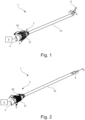
- Figure 1 shows in perspective a medical hand instrument 1 according to an embodiment of the present disclosure.
- the medical hand instrument 1 has a medical motor handpiece 2 according to the disclosure, which has a proximal handle section 4 and which, as in Fig. 1 shown schematically, can be coupled to a drive unit 6.
- the drive unit 6 can also be accommodated in the motor handpiece 2 and supplied with energy via a power supply connection.
- the hand instrument 1 has a distal tool (end effector/effector section) 8, which can be coupled to or decoupled from the motor handpiece 2, in particular to the handle section 4, via a (tool) shaft 10.
- the tool 8 can be designed, for example, as a milling cutter, drill or polishing head.
- the tool 8 can be angled relative to the shaft 10 (in Fig. 1 indicated by arrow C). Ie, as described in more detail below, the tool 8 and the shaft 10 can be angled relative to one another in such a way that a longitudinal axis S1 of the tool 8 and a shaft longitudinal axis S2 of the shaft 10 form an angle not equal to 180°, in particular smaller than 180° (cf . Fig. 6 ).
- a sleeve-shaped control element 12 is provided for this purpose in the hand instrument 1 according to the disclosure.
- the operating element 12 is arranged at a distal end section of the handle section 4 and is rotatable about a longitudinal axis of the handle in a first direction of rotation A and in a second direction of rotation B that is opposite to the first direction of rotation A.
- the motor handpiece 2 has the handle section 4 and the distally arranged operating element 12, which are arranged coaxially to one another, wherein the operating element 12 can be rotated relative to the handle section 4.
- a rotation of the operating element 12 from a neutral zero position, in which the tool 8 is not angled relative to the shaft 10, in the first direction of rotation A causes, as in Fig. 1 shown, an angling of the tool 8 relative to the shaft 10.
- the first direction of rotation A is defined in the hand instrument 1 according to the present disclosure as a rotation of the operating element 12 relative to the handle section 4 to the left.
- the first direction of rotation A in a distal plan view of the tool 8 corresponds to a clockwise rotation of the operating element 12.
- the control element 12 in the hand instrument 1 can also be rotated in the second direction of rotation B, which is opposite to the first direction of rotation A, relative to the handle section 4.
- the second direction of rotation B is defined in the top view of the tool 8 as a rotation of the control element 12 counterclockwise or as a rotation to the right.
- a rotation of the operating element 12 in the second direction of rotation B causes the coupling of the tool 8 to be released with the shaft 10.
- Figs. 3 and 4 show partial sectional views of the hand instrument 1 according to the first embodiment.
- an adjusting pin 14 is arranged in the radial direction of the operating element 12.
- a radially outer end portion of the adjusting pin 14 is received in an axial groove 16, which is formed on an inner circumferential surface of the operating element 12.
- the adjusting pin 14 is received in a rotation transmission sleeve 18.
- the rotation transmission sleeve 18 is connected to the shaft 10 in a rotationally fixed manner, so that a movement of the adjusting pin 14 in the circumferential direction causes a rotation of the rotation transmission sleeve 18 and the shaft 10.
- control element when the control element is rotated, it moves 12 in In the first direction of rotation A or in the second direction of rotation B, the adjusting pin 14 in the axial groove 16 with the control element 12 and, depending on the direction of rotation, causes the tool 8 to be bent or ejected.
- Fig. 5 shows a longitudinal cross section of a distal end section of the hand instrument 1 in a straight shaft shape. Ie the control element 12 is not rotated relative to the handle section 4 (zero position). As a result, the tool 8 and the shaft 10 are not angled and the longitudinal axis S1 of the tool 8 is collinear with the shaft longitudinal axis S2. As in Fig. 5 To recognize, the shaft 10 has a proximal shaft section 20 that faces the handle section 4 and can be coupled to it, and a distal shaft section 22 that can be coupled to the tool 8.
- the proximal shaft section 20 and the distal shaft section 22 are therefore arranged in a line or have an angle of 0° to one another.
- the proximal shaft section 20 is designed essentially tubular and has an end face 24 positioned in the longitudinal axis S2 of the shaft at its distal end section.
- the distal shaft section 22 is also approximately tubular. The tube tapers towards the distal end.
- the distal shaft section 22 has an end face 26 positioned in the longitudinal axis S2 of the shaft at its proximal end section.
- the raised end faces 24, 26 each have an angle of attack of preferably 22.5° to a plane normal to the longitudinal axis S2 of the shaft. If the shaft 10 is in a straight shaft shape or stretched out, the two raised end faces 24, 26 are offset from one another in such a way that the long ends of the raised end faces 24, 26 lie opposite one another in relation to the shaft longitudinal axis S2.
- the employed end faces 24, 26 rest on one another.
- the raised end faces 24, 26 do not necessarily have to have an angle of attack of 22.5°. Angles of attack of, for example, 10°, 18°, 30°, 45° or any other angle of attack are also conceivable.
- the distal shaft portion 22 is designed to be coupled to the tool 8.
- the distal shaft section 22 represents a Tool holder, wherein the tool 8 is accommodated in the tool holder and is rotatably mounted relative to the tool holder, ie the distal shaft section 22.
- a first coupling device 28 is arranged in the distal shaft section 22.
- a second coupling device 30 is provided on the tool 8, which in a coupling state realizes a coupling between the tool 8 and the distal shaft section 22 by interacting with the first coupling device 28 in order to fix the tool 8 in the distal shaft section 22 in the axial direction A.
- a coupling state between the tool 8 and the distal shaft section 22 is shown. That is, the first coupling device 28, which is mounted in/on the distal shaft portion 22, and the second coupling device 30, which is provided on the tool 8, engage with each other.
- the tool 8 has a tool head/effector 32, for example a milling head, and a tool shank 34.
- the tool head 32 and the tool shank 34 are connected to one another in a rotationally fixed manner.
- the tool shaft 34 is rotatably mounted in the distal shaft section 22 using a rolling bearing unit 36.
- a drive shaft 38 extends through the proximal shaft section 20 and is non-rotatably connected to the tool shaft 34 and applies torque from the drive unit 6 to the tool shaft 34 in the form of a torque transmission train.
- the rolling bearing unit 36 has at least one, here exactly two, rolling bearings 40, more precisely ball bearings, which are spaced apart from one another in the axial direction A, but which can alternatively also be designed as plain bearings.
- the rolling bearings 40 are accommodated in a bearing housing 42, which is part of the rolling bearing unit 36.
- the second coupling device 30 is inserted into the bearing housing 42 and is therefore not provided directly on the tool 8.
- the rolling bearing unit 36 and thus also the bearing housing 42 is arranged fixed on the tool shank 34 in the axial direction A.
- the second coupling device 30 it would also be conceivable for the second coupling device 30 to be provided directly on the tool shank 34.
- the second coupling device 30 is designed as an axial securing groove 44 which extends or runs continuously in the circumferential direction of the bearing housing 42.
- the axial securing groove 44 preferably has a semicircular or circular segment-shaped cross section.
- the first coupling device 28, which is provided in the distal shaft section 22, has at least one locking ball 46.
- the diameter of the locking ball 46 is selected so that the locking ball 46 can be accommodated in the axial locking groove 44.
- the axial locking groove 44 preferably completely surrounds at least one section of the locking ball 46 that contacts the axial locking groove 44.
- the locking ball 46 is held in the axial locking groove 44 on its side opposite the axial locking groove 44 by a distal end of a locking pin/slider 48.
- the locking pin 48 is part of the first coupling device 28.
- the locking pin 48 is fixed in the radial direction R.
- the locking pin 48 is displaceable or movable in the distal shaft section 22 in the axial direction.
- the proximal shaft section 20 has a fixed outer tube 50, a ring gear 52 with internal teeth 54, a pinion 56 with external teeth 58 and an eccentric locking bushing 60.
- the ring gear 52 is positioned within the outer tube 50 and the longitudinal axis of the outer tube 50 corresponds to the longitudinal axis of the ring gear 52.
- the outer tube 50 and the ring gear 52 are therefore arranged concentrically.
- the ring gear 52 is connected to the rotation transmission sleeve 18, ie to the operating element 12, via a hollow shaft 62 accommodated in the proximal shaft section 20.
- the outer tube 50 is designed as a stationary tube and therefore does not move.
- the distal end of the outer tube 50 has the raised end face 24.
- the distal end of the outer tube 50 also has a receiving bore 64 and a receiving pin for a rolling bearing 66.
- the outer tube 50 has a groove/groove for the balls of the rolling bearing 66.
- the distal shaft section 22 is mounted on the roller bearing 66.
- the internal toothing 54 meshes with the external toothing 58 of the pinion 56.
- a rotation of the ring gear 52 which is controlled by the operating element 12, is transmitted to the pinion 56.
- the direction of rotation of the pinion 56 is set equal to the direction of rotation of the ring gear 52.
- the pinion 56 is driven by the ring gear 52, but the pinion 56 rotates in the eccentric locking bushing 60.
- the locking bushing 60 is arranged eccentrically to the ring gear 52. This means that the longitudinal axis of the eccentric securing bushing 60 is parallel to the longitudinal axis of the ring gear 52, but the longitudinal axes are not one above the other or offset from one another.
- the distal shaft section 22 has an adjustment bushing 68.
- the adjustment bushing 68 is stored in the receiving bore 64 of the proximal shaft section 20.
- the adjustment bushing 68 is connected to the pinion 56 via a flexible silicone hose 70 in such a way that a rotation of the pinion 56 is transmitted to the adjustment bushing 68.
- the flexible silicone hose 70 is attached to the adjustment bushing 68 and the pinion 56, for example by welding or gluing.
- the adjustment bushing 68 is also positively connected to the distal shaft section 22 via a driving pin (not shown), so that a rotation of the adjustment bushing 68 is transmitted to the distal shaft section 22.
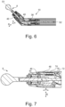
- Fig. 6 shows a longitudinal cross section through the distal end section of the shaft 10, the distal shaft section 22 being angled by 45° relative to the proximal shaft section 20 at a respective angle of attack of the two end faces 24, 26 by 22.5°.
- the distal shaft section 22 is compared to the position in Fig. 5 rotated by 180° around its own longitudinal axis S1.
- the employed end faces 24, 26 lie In this position, they are completely/flatly on top of each other again.
- the long ends of the raised end faces 24, 26 are positioned next to one another.
- the angles of attack of the turned end faces 24, 26 thus add up.
- the distal shaft section 22 is angled by twice the angle of attack of the raised end faces 24, 26 compared to the proximal shaft section 20.
- the driving pin is arranged opposite the securing bushing 60.
- the 45° position represents the reversal point for this construction.
- the adjustment bushing 68 has rotated through 180° in this position. If the ring gear 52, ie the operating element 12, rotates further, the distal shaft section 22 would rotate back into the starting position (zero position).
- Fig. 6 It can be seen that the locking ball 46 is held by the locking pin 48 in the radial direction R in the axial securing groove 44 even when the distal shaft section 22 is angled in the maximum adjustable angular position or maximum angle with respect to the proximal shaft section 20. In this way, the tool 8 is also secured in this angular position in the axial direction A in the distal shaft section by the engagement between the first coupling device 28 and the second coupling device 30.
- the torque train in particular the drive shaft 38, towards the tool shaft 34, which is arranged in the transition region between the distal shaft section 22 and the proximal shaft section 20, is flexible.
- This flexible section of the torque train allows the distal section of the tool shaft 34 with tool head 32 to be angled together with the distal shaft section 22 relative to the torque train in the proximal shaft section 20.
- the flexible section of the torque train is designed so that it can continue to transmit a torque that is exerted on a proximal section of the tool shank 34 to the tool head 32.
- Fig. 7 is a longitudinal sectional view of the distal end portion of the shaft 10 in a release state between the tool 8 and the distal shaft portion 22. That is, in FIG Fig. 7 In the position shown, the first coupling device 28 and the second coupling device 30 are not in active engagement with one another, so that the tool 8 can be removed or changed. In order to release the active engagement of the first coupling device 28 and the second coupling device 30, the operating element 12 is rotated in the second direction of rotation B (cf. Fig. 2 ). As explained in more detail below, the locking ball 46 is no longer accommodated in the axial locking groove 44. Instead, it is held by the locking pin 48 in the radial direction R against an outer peripheral surface of the bearing housing 42.
- the locking pin 48 must move in the axial direction A towards the proximal shaft section 20. This is prevented in the coupling state by the circumferential edge 63 of the proximal shaft section 20. However, the edge 63 is interrupted at one point of a locking pin receiving recess 72.
- the distal shaft section 22 rotates relative to the proximal shaft section 20 in a direction opposite to the bending, for example by (-)18 °, until the locking pin 48 is positioned relative to the proximal shaft section 20 is that it is at the same height as the locking pin receiving recess 72 in the circumferential direction.
- a biasing element 74 which is part of the first coupling device 28, presses the locking pin 48 in the axial direction A towards the proximal shaft section 20.
- the biasing element 74 thus pushes the locking pin 48, more precisely its proximal end, which is designed as a locking projection 76, into the locking pin receiving recess 72.
- the position in which the locking pin 48 is when its locking projection 76 engages the locking pin receiving recess 72 is referred to as the release state or release position.
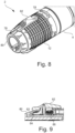
- Fig. 8 shows a perspective view of the distal end section of the motor handpiece 2 according to the first embodiment, without the shaft 10 being coupled to the handle section 4.
- a rotation of the operating element 12 in the first direction of rotation A causes the tool 8 to bend
- a rotation of the operating element 12 in the second direction of rotation B releases the coupling between the tool 8 and the shaft 10, or the distal shaft section 22, by releasing the operative engagement between the first coupling device 28 and the second coupling device 30.
- indicators 78 in the form of arrows which indicate the directions of rotation, are attached to the control element 12.
- the user can quickly identify which direction of rotation corresponds to which function when operating the hand instrument 1. For this are as in Fig. 8 shown, on an outer peripheral surface of the indicator sleeve 80 different angular positions, which each correspond to a defined rotation of the control element 12 in the first direction of rotation A and thus a defined angling of the tool 8 relative to the shaft 10, as well as a lock symbol or a symbol of a with the lock open.
- the user can therefore assign the respective function, namely angling or uncoupling, to the individual directions of rotation A, B.
- the motor handpiece 2 together with the control element 12 thus enables intuitive operation and integration of the two functions.
- a locking slide 82 is arranged on the motor handpiece 2 according to the first embodiment.
- the locking slide 82 is fixed in the operating element 12 in the radial and circumferential directions so that the locking slide 82 can only move in the axial direction relative to the operating element 12 between a (distal) locking and a (proximal) unlocking position.
- In the locking position can the control element 12, as explained in more detail below, cannot be rotated relative to the handle section 4.
- a distal pin section 83 of the locking slide 82 locks in the locking position, as in Fig. 9 shown, with an indicator locking ring 84 accommodated in the indicator sleeve 80.
- the indicator locking ring 84 has a plurality of recesses distributed over the circumference, into which the pin section 83 projects in the locking position, in order to fix or fix the control element 12 in the circumferential direction relative to the handle section 4 .hold on.
- the recesses of the indicator locking ring 84 preferably correspond to the indicators 78 attached to the outer circumferential surface of the indicator sleeve 80. The user can therefore simply set the tool 8 to be angled at a defined angle and fix the angled tool 8 at this angle.
- the locking slide 82 In order to be able to rotate the operating element 12 relative to the handle section 4 to adjust the angle or to release the clutch, the locking slide 82 must therefore be moved from the locking position to the unlocking position, i.e. in the proximal direction.
- the locking slide 82 is biased in the axial direction against the operating element 12 via a spring element 86.
- the spring element 86 is arranged between the locking slide 82 and a stop surface of the operating element 12 in such a way that it presses the locking slide 82 into the locking position, i.e. in the distal direction.
- the spring element 86 consequently exerts an automatic restoring force on the locking slide 82 in order to hold it in the locking position.
- the motor handpiece 2 does not have a spring element 86.
- the user must pull the locking slide 82 in the proximal direction to unlock and actively push it in the distal direction to lock.
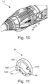
- a screw pin in the form of a ball pressure element 88 is provided in the motor handpiece 2.
- This has a spring element 90, which has a ball 92 in the proximal direction against an annular sliding link 94 (see Fig. 11 ) presses.
- Dome-shaped locking recesses 96 are formed on the sliding link 94, which can at least partially accommodate the ball 92.
- the locking recesses 96 are formed in the locking section 98 of the slide gate 94.
- the sliding link 94 includes the stop section 100.
- the stop section 100 is designed with a smooth/flat surface.
- the latching section 98 and the stop section 100 are separated from one another by a first stop 102 and a second stop 104, which protrude from the sliding link 94.
- the first stop 102 contains a drain ramp 106.
- the locking recesses 96 similar to the recesses of the indicator locking ring 84, correspond to defined angles through which the tool 8 can be angled relative to the shaft 10 when the operating element 12 is rotated in a certain way. That is, when the control element 12 is rotated by the defined angle relative to the handle section 4, the ball pressure element 88 rotates with the control element 12 until the defined angle is reached, at which the ball 92 falls into the corresponding locking recess 96 due to the preload force of the spring element 90 the slide gate 94 takes effect. The additional ball pressure element 88 therefore enables haptic feedback for the user when adjusting the angle.
- Fig. 12 shows a sectional view of the motor handpiece 2 in an adjustment/assembly state.
- the control element 12 includes a first adjustment thread 108, which receives the ball pressure element 88. Furthermore, the control element 12 includes a second adjustment thread 110, which receives a stop pin 112.
- the first adjustment thread 108 is positioned so that the ball pressure element 88 contacts the locking section 98 of the slide gate 94.
- the second adjustment thread 110 is positioned so that the stop pin 112 contacts the stop portion 100.
- the first adjustment thread 108 and the second adjustment thread 110 extend longitudinally to a motor handpiece longitudinal axis ML1. In the embodiment shown here, the first adjustment thread 108 extends the second adjustment thread 110 parallel to the motor handpiece longitudinal axis ML1.
- the first adjustment thread 108 and the second adjustment thread 110 are positioned diametrically opposite one another with respect to the motor handpiece longitudinal axis ML1.
- An adjusting bore 114 is formed in a distal extension of the first adjusting thread 108 and the second adjusting thread 110.
- the ball pressure element 88 or the stop pin 112 can be adjusted and brought into contact with the sliding gate 94 with a predetermined torque.
- a screwdriver or the like can be brought into contact with the stop pin 112 and/or the ball pressure element 88 through the adjustment hole and the stop pin 112 and/or the ball pressure element 88 in a mounted state in a direction of the motor handpiece longitudinal extension, preferably in a direction of the motor handpiece longitudinal axis, be adjusted.
- the adjustment holes 114 are each inclined towards the motor handpiece longitudinal axis ML1.
- An adhesive can be applied (after adjustment) to the stop pin 112 and the ball pressure element 88 through the adjustment holes 114. In this way, the stop pin 112 and the ball pressure element 88 can be fixed in the adjusted state.
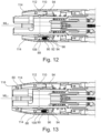
- Fig. 13 shows a sectional view of the motor handpiece 2 in an assembled state.
- the indicator sleeve/indicator ring/locking ring 80 closes the adjustment bore 114 in the distal direction.
- the indicator ring/locking ring 80 is preferably fixed on the motor handpiece 2 with a snap ring 116 in such a way that it can only be removed using a tool. In this way, it can be prevented that an adjustment of the stop pin 112 and/or the ball pressure element 88 is manipulated/adjusted by an unauthorized user.
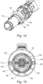
- Fig. 14 and Fig. 15 illustratively shows the motor handpiece 2 without the control element 12.
- the stop pin 112 and the ball pressure element 88 are arranged on the diameter of the sliding link 94.
- the ball pressure element 88 and the stop pin 112 are arranged so that their distance is maximum.
- the ball pressure element 88 and the Stop pin 112 arranged diametrically opposite.
- the arrangement of the locking recesses 96 on the locking section 98 of the sliding gate 94 corresponds to the predefined angles of the tool 8. The arrangement explicitly does not have to be evenly distributed over the locking section 98 of the sliding gate 94.
- Fig. 16 is a detailed view of the stop pin 112.
- the stop pin 112 includes a screw head drive 118, which in the embodiment shown here is designed as a slotted screw head drive.
- the stop pin further includes an external thread 120, which is provided and designed to engage in the adjusting thread 110 of the operating element 12.
- the stop element 122 is formed on an end section of the stop pin 112 facing away from the screw head drive 118.
- the stop element 122 has a substantially cylindrical shape.
- the stop pin 112 contains the sliding section 124, which is provided and designed to slide on the sliding link 94.
- the sliding section 124 is spherical in shape in order to minimize a contact area between the sliding section 124 and the sliding link 94.
- Fig. 17 is a detailed view of the ball pressure element 88.
- the ball pressure element 88 includes a screw head drive 118, which in the embodiment shown here is designed as a slotted screw head drive.
- the stop pin further includes an external thread 120 which is provided and designed to engage in the adjustment thread 110 of the operating element 12.
- a spring section 126 is formed on an end section of the ball pressure element 88 facing away from the screw head drive 118.
- the spring section 126 is designed as a hollow cylinder, in the interior of which the spring element 90 and the ball 92 are guided (cf. Fig. 10 , Fig. 12 and Fig. 13 ).
- the screw head drive 118 of the ball pressure element 88 can be designed as a screw stamp, via which a preload force on the spring element 90 can be adjusted.
- a single screw pin can be designed, which takes on the function of both the stop pin 112 and the ball pressure element 88.
- the sliding gate 94 can be designed with only one of the first stop 102 or the second stop 104.
Landscapes
- Health & Medical Sciences (AREA)
- Surgery (AREA)
- Life Sciences & Earth Sciences (AREA)
- Biomedical Technology (AREA)
- Medical Informatics (AREA)
- Orthopedic Medicine & Surgery (AREA)
- Oral & Maxillofacial Surgery (AREA)
- Engineering & Computer Science (AREA)
- Dentistry (AREA)
- Heart & Thoracic Surgery (AREA)
- Nuclear Medicine, Radiotherapy & Molecular Imaging (AREA)
- Molecular Biology (AREA)
- Animal Behavior & Ethology (AREA)
- General Health & Medical Sciences (AREA)
- Public Health (AREA)
- Veterinary Medicine (AREA)
- Dental Tools And Instruments Or Auxiliary Dental Instruments (AREA)
Abstract
Die Offenbarung betrifft ein medizinisches Motorhandstück (2) zum Antreiben eines distalen Endeffektors (32), mit einem Handgriffabschnitt (4), einem vorzugsweise hülsenförmigen Bedienelement (12), das um eine Handgrifflängsachse drehbar an einem distalen Endabschnitt des Handgriffabschnitts (4) gehalten ist und mit dem Endeffektor (32) derart koppelbar ist, um eine Drehbewegung des Bedienelements (12) in eine Bewegung des Endeffektors (32) zu transformieren oder eine Funktion am Endeffektor (32) zu bewirken und eine Rast- und/oder Anschlageinheit, die dafür vorgesehen und ausgebildet ist, die Drehbewegung des Bedienelements (12) an Endpositionen zu begrenzen und/oder einen Drehbewegungswiderstand auf das Bedienelement (12) in wenigstens einer Drehzwischenposition zu erhöhen.Die Rast- und/oder Anschlageinheit weist zumindest einen Schraubstift (88; 112), welcher längs zur Handgrifflängsachse sich erstreckend in ein Einstellgewinde (108, 110) des Bedienelements (112) eingeschraubt ist, und eine Abgleitkulisse (94) auf, die drehfest am Handgriffabschnitt (4) gehalten und mit dem zumindest einen Schraubstift (88; 112) in Gleiteingriff bringbar ist.The disclosure relates to a medical motor handpiece (2) for driving a distal end effector (32), having a handle section (4), a preferably sleeve-shaped operating element (12), which is held on a distal end section of the handle section (4) so that it can rotate about a longitudinal axis of the handle and can be coupled to the end effector (32) in such a way as to transform a rotational movement of the operating element (12) into a movement of the end effector (32) or to effect a function on the end effector (32) and a latching and/or stop unit provided for this purpose and is designed to limit the rotational movement of the operating element (12) at end positions and/or to increase a rotational movement resistance on the operating element (12) in at least one intermediate rotational position. The latching and/or stop unit has at least one screw pin (88; 112), which is screwed into an adjusting thread (108, 110) of the control element (112) extending along the longitudinal axis of the handle, and a sliding link (94) which is held non-rotatably on the handle section (4) and with which at least one screw pin (88; 112) can be brought into sliding engagement.
Description
Die Offenbarung betrifft ein medizinisches Motorhandstück mit einer Rast-und/oder Anschlageinheit sowie ein medizinisches Handinstrument mit dem medizinischen Motorhandstück.The disclosure relates to a medical motor handpiece with a latching and/or stop unit and a medical hand instrument with the medical motor handpiece.
In der modernen minimalinvasiven Chirurgie werden derartige Werkzeuge/Instrumente und dazugehörige Instrumentenhandstücke/Handinstrumente beispielsweise zur Bearbeitung von Knochen, Knorpeln bei arthroskopischen Eingriffen, in der Wirbelsäulenchirurgie und dergleichen orthopädischen/chirurgischen Behandlungen sowie zur Bearbeitung von organischem Material in der Neurochirurgie verwendet. Die Werkzeuge/Instrumente weisen ein(en) Handstück/Handgriff/Griffabschnitt und ggf. austauschbare Effektoren, wie beispielsweise Fräser, Drehmesser, einen Polierkopf oder Ähnliches auf. Der Effektor ist in einem Schaft des Werkzeugs/Instruments an dessen distalem Ende gelagert, ggf. drehbar angetrieben gelagert. Als Werkzeugantrieb ist je nach Verwendungszweck und beabsichtigter Werkzeugdrehzahl ein hydraulischer, pneumatischer, oder elektromotorischer Antrieb vorgesehen, der über einen Drehmoment-Übertragungszug innerhalb des Werkzeugs und/ oder des Handinstruments bzw. des Griffabschnitts mit dem Werkzeugkopf (Effektor) wirkverbunden ist. Die Antriebe können dabei im Werkzeug und/oder im Handinstrument integriert oder als externe Antriebseinheiten ausgebildet sein, die über Energieversorgungsleitungen oder Drehmoment-Übertragungsstränge mit dem Werkzeug oder dem Handinstrument gekuppelt sind.In modern minimally invasive surgery, such tools/instruments and associated instrument handpieces/hand instruments are used, for example, for processing bones, cartilage in arthroscopic procedures, in spinal surgery and similar orthopedic/surgical treatments, as well as for processing organic material in neurosurgery. The tools/instruments have a handpiece/handle/handle section and possibly replaceable effectors, such as milling cutters, rotary knives, a polishing head or the like. The effector is mounted in a shaft of the tool/instrument at its distal end, possibly rotatably driven. Depending on the intended use and the intended tool speed, a hydraulic, pneumatic or electric motor drive is provided as a tool drive, which is operatively connected to the tool head (effector) via a torque transmission train within the tool and/or the hand instrument or the handle section. The drives can be integrated in the tool and/or in the hand instrument or can be designed as external drive units that are coupled to the tool or the hand instrument via power supply lines or torque transmission lines.
Dabei ist es vorteilhaft, den distalen Schaftabschnitt eines Schafts von einem medizinischen Handinstrument abzuwinkeln, um so Operationen in geringem Raum durchführen zu können, beispielsweise bei Operationen an der Wirbelsäule. Anders ausgedrückt, spielt bei chirurgischen, insbesondere minimal-invasiven, Eingriffen der Bauraum der verwendeten Instrumente und eine gute Handhabbarkeit eine große Rolle. So sollen die Instrumentenschäfte insbesondere im Bereich der distalen Effektoren auf möglichst kleinem Raum aktiv (über einen Betätigungsmechanismus gewollt ausgeführt) abwinkelbar sein.It is advantageous to angle the distal shaft section of a shaft of a medical hand instrument in order to be able to carry out operations in a small space, for example during operations on the spine. In other words, in surgical, especially minimally invasive, procedures, the Installation space of the instruments used and easy handling play a major role. The instrument shafts should be able to be actively angled (designed via an actuation mechanism) in the smallest possible space, particularly in the area of the distal effectors.
Hierbei ist von großer Bedeutung, dass der Betätigungsmechanismus durch einen Bediener intuitiv und sicher bedient werden kann, auch ohne dass der Bediener seinen Blick von einer Eingriffsstelle des Effektors abwendet, um eine Patientensicherheit zu erhöhen. Anders ausgedrückt ist es wünschenswert, dass der Bediener den Betätigungsmechanismus blind bedienen kann.It is of great importance here that the actuation mechanism can be operated intuitively and safely by an operator, even without the operator taking his eyes off an engagement point on the effector, in order to increase patient safety. In other words, it is desirable that the operator can operate the operating mechanism blindly.
Abwinkelbare Schäfte für medizinische Handinstrumente sind hinlänglich bekannt und weisen üblicherweise einen proximalen und einen abwinkelbaren distalen Schaftabschnitt auf. Der distale Schaftabschnitt und der proximale Schaftabschnitt weisen dabei beide jeweils ein schräges Ende/ eine bezüglich der jeweiligen Schaftabschnittsachse angestellte Stirnseite auf. D.h. jeweils ein Ende/ Endabschnitt/ Stirnseite des distalen und proximalen Schaftabschnitts ist nicht gerade, sondern abgeschrägt/ angestellt. Die Schrägungen/ angestellten Endabschnitte/ Stirnseiten haben jeweils den im Wesentlichen gleichen Anstellwinkel. Darum passen die Schrägungen derart zueinander, dass der proximale und der distale Schaftabschnitt in einer bestimmten Relativdrehposition einen geraden Schaft/ ein gerades Rohr bilden. Wenn nun der distale Schaftabschnitt um seine Längsachse relativ zum proximalen Schaftabschnitt rotiert und der proximale Schaftabschnitt stehen bleibt, wird der distale Schaftabschnitt durch die angestellten Stirnseiten/ Endabschnitte zwangsläufig abgewinkelt.Bendable shafts for medical hand instruments are well known and usually have a proximal and a bendable distal shaft section. The distal shaft section and the proximal shaft section each have an oblique end/an end face that is positioned relative to the respective shaft section axis. This means that one end/end section/face of the distal and proximal shaft sections is not straight, but rather bevelled/inclined. The bevels/inclined end sections/end faces each have essentially the same angle of attack. That is why the bevels fit together in such a way that the proximal and distal shaft sections form a straight shaft/tube in a certain relative rotational position. If the distal shaft section now rotates about its longitudinal axis relative to the proximal shaft section and the proximal shaft section stops, the distal shaft section is inevitably angled by the raised end faces/end sections.
Beispielsweise sind in
Darüber hinaus zeigt
Ferner offenbart auch
Der Stand der Technik hat jedoch immer den Nachteil, dass das Bedienelement entweder keine Raststufen für verschiedene Winkelstellungen aufweist und somit kein haptisches Feedback an einen Bediener/Verwender ausgibt oder, wie in der
Es sind die Aufgaben und Ziele der Offenbarung, die Nachteile aus dem Stand der Technik zu beheben oder wenigstens zu mindern und insbesondere ein medizinisches Motorhandstück bereitzustellen, dessen Bedienelement einem Bediener ein haptisches Feedback ausgibt und dabei leicht zu montieren und zu justieren ist.The tasks and goals of the disclosure are to eliminate or at least reduce the disadvantages of the prior art and, in particular, to provide a medical motor handpiece whose control element gives an operator haptic feedback and is easy to assemble and adjust.
Die Aufgaben und Ziele werden hinsichtlich eines gattungsgemäßen medizinischen Motorhandstücks offenbarungsgemäß durch den Gegenstand des Anspruchs 1 sowie hinsichtlich eines gattungsgemäßen medizinisches Handinstrument mit dem medizinischen Motorhandstück offenbarungsgemäß durch den Gegenstand des Anspruchs 10 gelöst. Vorteilhafte Ausführungsformen sind in den Unteransprüchen beansprucht.The tasks and objectives are disclosed with regard to a generic medical motor handpiece by the subject matter of
Konkret wird die Aufgabe gelöst durch ein medizinisches Motorhandstück zum Antreiben eines distalen Endeffektors, mit einem Handgriffabschnitt, einem vorzugsweise hülsenförmigen Bedienelement und einer Rast- und/oder Anschlageinheit. Das hülsenförmige Bedienelement ist um eine Handgrifflängsachse drehbar an einem distalen Endabschnitt des Handgriffabschnitts gehalten und mit dem Endeffektor derart koppelbar, um eine Drehbewegung des Bedienelements in eine Bewegung des Endeffektors zu transformieren oder eine Funktion am Endeffektor zu bewirken. Die Rast- und/oder Anschlageinheit ist dafür vorgesehen und ausgebildet, die Drehbewegung des Bedienelements an Endpositionen zu begrenzen und/oder einen Drehbewegungswiderstand auf das Bedienelement in wenigstens einer Drehzwischenposition zu erhöhen. Die Rast- und/oder Anschlageinheit weist zumindest einen Schraubstift, welcher längs zur Handgrifflängsachse sich erstreckend in ein Einstellgewinde des Bedienelements eingeschraubt ist, und eine Abgleitkulisse auf, die drehfest am Handgriffabschnitt gehalten und mit dem zumindest einen Schraubstift in Gleiteingriff bringbar ist.Specifically, the task is solved by a medical motor handpiece for driving a distal end effector, with a handle section, a preferably sleeve-shaped control element and a latching and/or stop unit. The sleeve-shaped control element is rotatably held on a distal end section of the handle section about a longitudinal axis of the handle and can be coupled to the end effector in such a way as to transform a rotational movement of the control element into a movement of the end effector or to effect a function on the end effector. The latching and/or stop unit is intended and designed to limit the rotational movement of the operating element at end positions and/or to increase a rotational movement resistance on the operating element in at least one intermediate rotational position. The latching and/or stop unit has at least one screw pin, which is screwed into an adjusting thread of the operating element extending along the longitudinal axis of the handle, and a sliding link which is held non-rotatably on the handle section and can be brought into sliding engagement with the at least one screw pin.
In anderen Worten beinhaltet das medizinische Motorhandstück den Handgriffabschnitt, der vorgesehen und ausgebildet ist, von einem Benutzer gehalten zu werden, das Bedienelement, welches vorgesehen und ausgebildet ist, den distalen Endeffektor zu manipulieren, und die Rast- und/oder Anschlageinheit.In other words, the medical motor handpiece includes the handle portion provided and configured to be held by a user, the operating element provided and configured to manipulate the distal end effector, and the latching and/or stop unit.
Eine Bedienung des Bedienelements erfolgt durch ein Rotieren des vorzugsweise holzylinderförmigen Bedienelements um eine Mittelachse des Bedienelements. Die Rast- und/oder Anschlageinheit begrenzt einen Drehwinkel des Bedienelements um die Mittelachse. Alternativ und/oder zusätzlich erhöht die Rast- und/oder Anschlageinheit den Drehbewegungswiderstand an der zumindest einen Drehzwischenposition dergestalt, dass der Benutzer/Bediener/Verwender ein haptisches Feedback an der zumindest einen Drehzwischenposition bei der Bedienung des Bedienelements erhält.The control element is operated by rotating the preferably cylindrical control element about a central axis of the control element. The latching and/or stop unit limits a rotation angle of the control element about the central axis. Alternatively and/or additionally, the latching and/or stop unit increases the resistance to rotational movement at the at least one intermediate rotational position in such a way that the user/operator/user receives haptic feedback at the at least one intermediate rotational position when operating the control element.
Die Rast- und/oder Anschlageinheit beinhaltet den zumindest einen Schraubstift, der im Wesentlichen parallel oder alternativ in einem spitzen Winkel zu der Mittelachse des Bedienelements orientiert ist. Der zumindest eine Schraubstift ist in das Einstellgewinde des Bedienelements eingeschraubt, wobei ein Schraubenkopfantrieb des Schraubstifts in distaler Richtung ausgerichtet ist. Die Rast- und/oder Anschlageinheit beinhaltet weiterhin die Abgleitkulisse, welche proximal zu dem Schraubstift angeordnet ist. Die Abgleitkulisse ist drehfest mit dem Handgriffabschnitt verbunden. Ein proximaler Endabschnitt des Schraubstiftes kontaktiert die Abgleitkulisse oder ist zumindest ausgebildet, die Abgleitkulisse zu kontaktieren.The latching and/or stop unit contains the at least one screw pin, which is oriented essentially parallel or alternatively at an acute angle to the central axis of the operating element. The at least one screw pin is screwed into the adjustment thread of the operating element, with a screw head drive of the screw pin being aligned in the distal direction. The latching and/or stop unit also contains the sliding link, which is arranged proximal to the screw pin. The slide gate is connected to the handle section in a rotationally fixed manner. A proximal end section of the screw pin contacts the sliding gate or is at least designed to contact the sliding gate.
Durch die Ausbildung der Rast- und/oder Anschlageinheit mit dem zumindest einen Schraubstift und dem Einstellgewinde, in welches der zumindest eine Schraubstift eingreift, kann eine räumliche Anordnung zwischen Schraubstift und Abgleitkulisse optimal eingestellt werden. In anderen Worten kann eine exakte Positionierung der Rast- und/oder Anschlageinheit in Axialrichtung des medizinischen Motorhandstücks erfolgen und auf diese Weise eine präzise Anschlagposition sichergestellt werden. Toleranzen der verschiedenen Bauteile zueinander können durch die beschriebene Offenbarung und die sich hieraus ergebende stufenlose Justierbarkeit der Rast-und/oder Anschlageinheit vollständig eliminiert werden. Ein Haptisches Feedback für den Benutzer kann optimal eingestellt werden und damit eine (blinde) Bedienbarkeit und die Patientensicherheit erhöht werden.By designing the locking and/or stop unit with the at least one screw pin and the adjusting thread into which the at least one screw pin engages, a spatial arrangement between the screw pin and the sliding link can be optimally adjusted. In other words, the locking and/or stop unit can be positioned exactly in the axial direction of the medical motor handpiece and in this way a precise stop position can be ensured. Tolerances between the various components can be completely eliminated by the disclosed disclosure and the resulting continuous adjustability of the locking and/or stop unit. Haptic feedback for the user can be optimally set, thereby increasing (blind) usability and patient safety.
Kern der Erfindung ist das medizinische Motorhandstück mit der Rast- und/oder Anschlageinheit, wobei der zumindest eine Schraubstift der Rast- und/oder Anschlageinheit in ein Einstellgewinde, welches sich längs zu dem medizinischen Motorhandstück erstreckt, eingeschraubt ist und die Rast- und/oder Anschlageinheit genau justiert werden kann.The core of the invention is the medical motor handpiece with the latching and/or stop unit, wherein the at least one screw pin of the latching and/or stop unit is inserted into an adjusting thread which is longitudinal to the medical Motor handpiece extends, is screwed in and the locking and / or stop unit can be precisely adjusted.
In einem ersten Aspekt kann es sich bei dem zumindest einen Schraubstift um eine Mehrzahl von Schraubstiften handeln, welche als Anschlagstift und/oder als Kugeldruckstück ausgebildet sein können, wobei eine Anzahl an Anschlagstiften vorzugsweise einer Anzahl an Kugeldruckstücken entspricht.In a first aspect, the at least one screw pin can be a plurality of screw pins, which can be designed as a stop pin and/or as a ball pressure piece, with a number of stop pins preferably corresponding to a number of ball pressure pieces.
In anderen Worten kann der zumindest eine Schraubstift als der Anschlagstift und/oder als das Kugeldruckstück ausgebildet sein. Vorzugsweise ist sowohl zumindest ein Anschlagstift als auch zumindest ein Kugeldruckstück ausgebildet. Der Anschlagstift kann vorgesehen und ausgebildet sein, den Drehwinkel des Bedienelements um die Mittelachse des Bedienelements zu begrenzen. Das Kugeldruckstück kann vorgesehen und ausgebildet sein, den Drehbewegungswiderstand an der zumindest einen Drehzwischenposition zu erhöhen. Das Kugeldruckstück kann an einem proximalen Endabschnitt des Kugeldruckstücks eine durch eine Feder federvorgespannte Kugel beinhalten, welche an der zumindest einen Drehzwischenposition in eine kalottenförmige Vertiefung der Abgleitkulisse eingreift. Um das Bedienelement aus der Drehzwischenposition zu bewegen, muss zumindest eine Federkraft der Feder überwunden werden, was ein haptisches Feedback für den Benutzer bedeutet.In other words, the at least one screw pin can be designed as the stop pin and/or as the ball pressure piece. Preferably, both at least one stop pin and at least one ball pressure piece are formed. The stop pin can be provided and designed to limit the angle of rotation of the control element about the central axis of the control element. The ball pressure piece can be provided and designed to increase the resistance to rotational movement at the at least one intermediate rotational position. At a proximal end portion of the ball pressure piece, the ball pressure piece can contain a ball which is spring-loaded by a spring and which engages in a dome-shaped recess of the sliding link at the at least one intermediate rotational position. In order to move the control element from the intermediate rotation position, at least one spring force of the spring must be overcome, which means haptic feedback for the user.
Durch ein Ausbilden des zumindest einen Schraubstifts als Anschlagstift und/oder als Kugeldruckstück kann sowohl ein maximaler Verdrehwinkel des Bedienelements definiert/begrenzt sein als auch die zumindest eine Drehzwischenposition für den Benutzer haptisch erfühlbar gemacht werden.By designing the at least one screw pin as a stop pin and/or as a ball pressure piece, both a maximum angle of rotation of the control element can be defined/limited and the at least one intermediate rotation position can be made haptically tangible for the user.
In einem weiteren Aspekt kann das Kugeldrückstück eine federvorgespannte Kugel beinhalten, wobei eine Vorspannkraft des Kugeldrückstücks über das Einstellgewinde einstellbar sein kann.In a further aspect, the ball pressure piece can contain a spring-loaded ball, wherein a preload force of the ball pressure piece can be adjustable via the adjusting thread.
In einem weiteren Aspekt kann es sich bei dem zumindest einen Schraubstift um genau zwei Schraubstifte handeln, welche auf einem konstanten Radius um eine Mittelfaster des Motorhandstücks, vorzugsweise gegenüberliegend auf einem Kreisdurchmesser, angeordnet sein können.In a further aspect, the at least one screw pin can be exactly two screw pins, which can be arranged on a constant radius around a central part of the motor handpiece, preferably opposite one another on a circular diameter.
In anderen Worten kann die Rast- und/oder Anschlageinheit jeweils genau den einen Anschlagstift und das eine Kugeldruckstück beinhalten. Der Anschlagstift und das Kugeldruckstück können diametral gegenüberliegend bezogen auf eine Mittelachse des Bedienelements angeordnet sein.In other words, the latching and/or stop unit can contain exactly one stop pin and one ball pressure piece. The stop pin and the ball pressure piece can be arranged diametrically opposite one another with respect to a central axis of the operating element.
Durch eine derartige Anordnung der Schraubstifte kann eine gleichmäßige axiale Krafteinleitung der Schraubstifte in die Abgleitkulisse sichergestellt werden und ein Verkippen der Abgleitkulisse, was zu einer Verklemmung des Bedienelements führen könnte, verhindert werden.By arranging the screw pins in this way, a uniform axial introduction of force of the screw pins into the sliding link can be ensured and tilting of the sliding link, which could lead to jamming of the control element, can be prevented.
In einem weiteren Aspekt kann sich an das Einstellgewinde in distaler Richtung eine Einstellbohrung anschließen.In a further aspect, an adjustment bore can be connected to the adjustment thread in the distal direction.
Anders ausgedrückt kann das Einstellgewinde in distaler Richtung durch die Einstellbohrung fortgesetzt sein. Dabei kann sich die Einstellbohrung in einer identischen Orientierung wie das Einstellgewinde längs des medizinischen Motorhandstücks erstrecken.In other words, the adjustment thread can be continued in the distal direction through the adjustment hole. The adjustment hole can extend along the medical motor handpiece in an identical orientation as the adjustment thread.
Alternativ kann eine Erstreckungsrichtung der Einstellbohrung in einem Winkel, vorzugsweise kleiner 10 °, zu einer Erstreckungsrichtung des Einstellgewindes geneigt sein.Alternatively, an extension direction of the adjustment bore can be inclined at an angle, preferably less than 10°, to an extension direction of the adjustment thread.
Die Einstellbohrung kann sich zwischen einem distalen Endabschnitt des Einstellgewindes und einem distalen Endabschnitt des Bedienelements, vorzugsweise einer distalen Endfläche des Bedienelements, erstrecken.The adjustment bore can extend between a distal end portion of the adjustment thread and a distal end portion of the operating element, preferably a distal end surface of the operating element.
Durch die Einstellbohrung kann der zumindest eine Schraubstift in einem montierten Zustand justiert werden. In anderen Worten kann die Rast- und/oder Anschlageinheit in einem Zustand, in welchem das medizinische Motorhandstück vollständig oder zumindest beinahe vollständig montiert ist (fein-) justiert werden.Through the adjustment hole, the at least one screw pin can be adjusted in an assembled state. In other words, the latching and/or stop unit can be (finely) adjusted in a state in which the medical motor handpiece is completely or at least almost completely assembled.
In einem weiteren Aspekt kann die Einstellbohrung in distaler Richtung zu einer Mittelfaser des medizinischen Motorhandstücks hin geneigt orientiert sein.In a further aspect, the adjustment bore can be oriented in a distal direction inclined towards a central fiber of the medical motor handpiece.
In anderen Worten kann ein Abstand zwischen einer Mittelfaser der Einstellbohrung und der Mittelfaser des medizinischen Motorhandstücks in einem distalen Abschnitt der Einstellbohrung kleiner sein als in einem proximalen Abschnitt der Einstellbohrung.In other words, a distance between a center fiber of the adjustment hole and the center fiber of the medical motor handpiece may be smaller in a distal portion of the adjustment hole than in a proximal portion of the adjustment hole.
Durch eine Neigung der Einstellbohrung kann eine Außengeometrie des medizinischen Motorhandstücks derart gestaltet sein, dass das medizinische Motorhandstück sich in distaler Richtung verschlankt. Auf diese Weise kann eine Handhabbarkeit des medizinischen Motorhandstücks verbessert werden.By inclining the adjustment hole, an external geometry of the medical motor handpiece can be designed such that the medical motor handpiece becomes slimmer in the distal direction. In this way, the handling of the medical motor handpiece can be improved.
In einem weiteren Aspekt kann die Einstellbohrung distal durch einen Rastring verschlossen sein.In a further aspect, the adjustment bore can be closed distally by a locking ring.
In anderen Worten kann das Bedienelement distal durch den Rastring begrenzt sein.In other words, the operating element can be limited distally by the locking ring.
Auf diese Weise kann verhindert werden, dass die Justierung des zumindest einen Schraubstifts durch einen unautorisierten Dritten verändert wird oder es zu einer unbeabsichtigten Veränderung der Justierung des zumindest einen Schraubstifts kommt. Weiterhin verhindert der Rastring ein Eindringen von Schmutz und Fremdpartikeln in die Einstellbohrung. Bevorzugt ist der Rastring drehfest mit dem Hangriffabschnitt verbunden. Weiterhin bevorzugt ist der Rastring derart mit dem medizinischen Motorhandstück verbunden, dass der Rasrting nicht werkzeuglos demontiert werden kann.In this way, it can be prevented that the adjustment of the at least one screw pin is changed by an unauthorized third party or that the adjustment of the at least one screw pin is unintentionally changed. Furthermore, the locking ring prevents dirt and foreign particles from entering the adjustment hole. The locking ring is preferably connected to the handle section in a rotationally fixed manner. Furthermore, the locking ring is preferably connected to the medical motor handpiece in such a way that the locking ring cannot be dismantled without tools.
In einem weiteren Aspekt kann der zumindest eine Schraubstift mittels Klebstoff fixiert sein.In a further aspect, the at least one screw pin can be fixed using adhesive.
Anders ausgedrückt kann nach einer Justierung des zumindest einen Schraubstifts ein Klebstoff in die Einstellbohrung eingebracht werden und/oder die Einstellbohrung mit Klebstoff verfüllt werden.In other words, after adjusting the at least one screw pin, an adhesive can be introduced into the adjustment hole and/or the adjustment hole can be filled with adhesive.
Auf diese Weise kann verhindert werden, dass die Justierung des zumindest einen Schraubstifts durch einen unautorisierten Dritten verändert wird oder es zu einer unbeabsichtigten Veränderung der Justierung des zumindest einen Schraubstifts kommt. Weiterhin verhindert der Klebstoff ein Eindringen von Schmutz und Fremdpartikeln in die Einstellbohrung.In this way, it can be prevented that the adjustment of the at least one screw pin is changed by an unauthorized third party or that the adjustment of the at least one screw pin is unintentionally changed. Furthermore, the adhesive prevents dirt and foreign particles from entering the adjustment hole.
In einem weiteren Aspekt kann die Abgleitkulisse ringförmig ausgebildet sein und auf einer distalen Stirnseite einen ersten Abschnitt mit Rastlöchern und einen zweiten glatten Abschnitt beinhalten.In a further aspect, the sliding link can be annular and contain a first section with locking holes and a second smooth section on a distal end face.
In anderen Worten kann die Abgleitkulisse den ersten Abschnitt beinhalten, der vorgesehen und ausgebildet ist, mit dem vorzugsweise einen Anschlagstift in Gleitkontakt zu stehen und den zweiten Abschnitt beinhalten, der Rastlöcher bzw. kalottenförmige Vertiefungen beinhaltet, welche vorgesehen und ausgebildet sind, mit dem vorzugsweise einen Kugeldruckstück in Kontakt zu stehen.In other words, the slide gate can include the first section, which is provided and designed to be in sliding contact with the preferably a stop pin, and the second section, which contains locking holes or dome-shaped depressions, which are provided and designed to be in sliding contact with the preferably one Ball pressure piece to be in contact.
Durch die Segmentierung der Abgleitkulisse kann sowohl eine Rastfunktion als auch eine Anschlagfunktion der Rast- und/oder Anschlageinheit zuverlässig umgesetzt werden. In anderen Worten kann durch eine Funktionstrennung eine Ausfallsicherheit der Rast- und/oder Anschlageinheit erhöht werden.By segmenting the sliding gate, both a latching function and a stop function of the latching and/or stop unit can be reliably implemented. In other words, a functional separation can increase the reliability of the latching and/or stop unit.
In einem weiteren Aspekt können der erste Abschnitt und der zweite Abschnitt durch Anschläge getrennt sein, welche in distaler Richtung von der Abgleitkulisse hervorstehen.In a further aspect, the first section and the second section can be separated by stops which protrude in the distal direction from the sliding link.
In einem weiteren Aspekt kann der Schraubenkopfantrieb des zumindest einen Schraubstifts als Schlitzschraubenkopf oder als Innensechskantkopf ausgebildet sein. Es sind jedoch weitere geeignete Schraubenkopfantriebe vorstellbar.In a further aspect, the screw head drive of the at least one screw pin can be designed as a slotted screw head or as a hexagon socket head. However, other suitable screw head drives are conceivable.
In einem weiteren Aspekt kann eine Federkraft des Kugeldrückstücks durch eine Einstellschraube einstellbar sein.In a further aspect, a spring force of the ball pressure piece can be adjustable by an adjusting screw.
Bei einem Justierungsvorgang können der zumindest eine Schraubstift mit einem vordefinierten Drehmoment angezogen werden und damit eine definierte Kontaktkraft zwischen Schraubstift und Abgleitkulisse gewährleistet werden.During an adjustment process, the at least one screw pin can be tightened with a predefined torque, thus ensuring a defined contact force between the screw pin and the sliding link.
Die Aufgabe der vorliegenden Offenbarung wird weiterhin gelöst durch ein medizinisches Handinstrument, welches ein medizinisches Motorhandstück nach einem der obigen Aspekte, einen Werkzeugschaft und einen Effektor beinhaltet.The object of the present disclosure is further solved by a medical hand instrument which includes a medical motor handpiece according to one of the above aspects, a tool shaft and an effector.
In einem Aspekt kann der Endeffektor relativ zu dem Werkzeugschaft abwinkelbar sein.In one aspect, the end effector can be angled relative to the tool shank.
Die Offenbarung wird nachfolgend anhand bevorzugter Ausführungsbeispiele mit Hilfe von Figuren näher erläutert. Es zeigen:
- Fig. 1
- eine perspektivische Ansicht eines medizinischen Handinstruments;
- Fig. 2
- eine weitere perspektivische Ansicht des medizinischen Handinstruments;
- Fig. 3
- eine Teillängsschnittansicht eines Motorhandstücks des medizinischen Handinstruments;
- Fig. 4
- eine Querschnittansicht des Motorhandstücks des medizinischen Handinstruments;
- Fig. 5
- eine Teillängsschnittansicht eines distalen Endabschnitts des medizinischen Handinstruments in einer geraden Schaftform;
- Fig. 6
- eine Teillängsschnittansicht des distalen Endabschnitts des medizinischen Handinstruments in einer abgewinkelten Schaftform;
- Fig. 7
- eine Teillängsschnittansicht des distalen Endabschnitts des medizinischen Handinstruments in einem Freigabezustand;
- Fig. 8
- eine isometrische Perspektivansicht des Motorhandstücks des medizinischen Handinstruments;
- Fig. 9
- eine Teillängsschnittansicht des Motorhandstücks des medizinischen Handinstruments;
- Fig. 10
- eine perspektivische Längsschnittansicht des medizinischen Handinstruments gemäß einer Modifikation;
- Fig. 11
- eine Detailansicht einer Abgleitkulisse des medizinischen Handinstruments gemäß der Modifikation;
- Fig. 12
- eine weitere Teillängsschnittansicht des Motorhandstücks des medizinischen Handinstruments;
- Fig. 13
- eine weitere Teillängsschnittansicht des Motorhandstücks des medizinischen Handinstruments;
- Fig. 14
- eine perspektivische Teilansicht des Motorhandstücks;
- Fig. 15
- eine Frontansicht des Motorhandstücks;
- Fig. 16
- eine Detailansicht eines Anschlagstifts;
- Fig. 17
- eine Detailansicht eines Kugeldrückstücks.
- Fig. 1
- a perspective view of a medical hand instrument;
- Fig. 2
- another perspective view of the medical hand instrument;
- Fig. 3
- a partial longitudinal section view of a motor handpiece of the medical hand instrument;
- Fig. 4
- a cross-sectional view of the motor handpiece of the medical hand instrument;
- Fig. 5
- a partial longitudinal sectional view of a distal end portion of the medical hand instrument in a straight shaft shape;
- Fig. 6
- a partial longitudinal section view of the distal end portion of the medical hand instrument in an angled shaft shape;
- Fig. 7
- a partial longitudinal section view of the distal end portion of the handheld medical instrument in a release state;
- Fig. 8
- an isometric perspective view of the motor handpiece of the medical hand instrument;
- Fig. 9
- a partial longitudinal section view of the motor handpiece of the medical hand instrument;
- Fig. 10
- a perspective longitudinal section view of the medical hand instrument according to a modification;
- Fig. 11
- a detailed view of a slide gate of the medical hand instrument according to the modification;
- Fig. 12
- another partial longitudinal section view of the motor handpiece of the medical hand instrument;
- Fig. 13
- another partial longitudinal section view of the motor handpiece of the medical hand instrument;
- Fig. 14
- a partial perspective view of the motor handpiece;
- Fig. 15
- a front view of the motor handpiece;
- Fig. 16
- a detailed view of a stop pin;
- Fig. 17
- a detailed view of a ball pressure piece.
Die Figuren sind schematischer Natur und dienen lediglich dem Verständnis der Offenbarung. Gleiche Elemente sind mit denselben Bezugszeichen versehen. Die Merkmale der verschiedenen Ausführungsbeispiele können untereinander ausgetauscht werden.The figures are schematic in nature and only serve to understand the revelation. The same elements are given the same reference numbers. The features of the different exemplary embodiments can be exchanged with one another.
Ferner weist das Handinstrument 1 ein distales Werkzeug (Endeffektor/Effektorabschnitt) 8 auf, welches über einen (Werkzeug-)Schaft 10 mit dem Motorhandstück 2, insbesondere mit dem Handgriffabschnitt 4, gekoppelt werden kann oder von diesem entkoppelt werden kann. Das Werkzeug 8 kann dabei beispielsweise als Fräser, Bohrer oder Polierkopf ausgeführt sein.Furthermore, the
Wenn der Schaft 10 mit dem Handgriffabschnitt 4 gekoppelt ist, wird Drehmoment von der Antriebseinheit 6 über einen in dem Handinstrument 1, insbesondere dem Handgriffabschnitt 4 und dem Schaft 10, angeordneten Drehmoment-Übertragungszug hin zu dem Werkzeug 8 übertragen, um dieses in Drehung zu versetzen. Bei Verwendung des Handinstruments 1 im Rahmen einer chirurgischen Operation bzw. medizinischen Behandlung ist es bekannt, dass das Werkzeug 8 relativ zu dem Schaft 10 abgewinkelt werden kann (in
Wie in
Eine Drehung des Bedienelements 12 aus einer neutralen Nullstellung, bei welcher das Werkzeug 8 nicht relativ zu dem Schaft 10 abgewinkelt ist, in der ersten Drehrichtung A bewirkt dabei, wie in
Wie in
Die angestellten Stirnseiten 24, 26 weisen jeweils einen Anstellwinkel von vorzugsweise 22,5° zu einer Normalenebene zur Schaftlängsachse S2 auf. Wenn der Schaft 10 in einer geraden Schaftform bzw. ausgestreckt ist, sind die beiden angestellten Stirnseiten 24, 26 derart zueinander versetzt, dass sich die langen Enden der angestellten Stirnseiten 24, 26 in Relation zur Schaftlängsachse S2 gegenüberliegen. Die angestellten Stirnseiten 24, 26 liegen aufeinander auf. Die angestellten Stirnseiten 24, 26 müssen dabei nicht zwangsläufig einen Anstellwinkel von 22,5° aufweisen. Es sind auch Anstellwinkel von beispielsweise 10°, 18°, 30°, 45° oder jeder andere Anstellwinkel denkbar.The raised end faces 24, 26 each have an angle of attack of preferably 22.5° to a plane normal to the longitudinal axis S2 of the shaft. If the
Wie vorstehend erwähnt, ist der distale Schaftabschnitt 22 ausgebildet, mit dem Werkzeug 8 gekoppelt zu werden. D.h. der distale Schaftabschnitt 22 stellt eine Werkzeugaufnahme dar, wobei das Werkzeug 8 in der Werkzeugaufnahme aufgenommen ist und relativ zu der Werkzeugaufnahme, d.h. dem distalen Schaftabschnitt 22, drehbar gelagert ist.As mentioned above, the
Hierfür ist in dem distalen Schaftabschnitt 22 eine erste Kupplungsvorrichtung 28 angeordnet. An dem Werkzeug 8 ist eine zweite Kupplungsvorrichtung 30 vorgesehen, die in einem Kupplungszustand durch Zusammenwirken mit der ersten Kupplungsvorrichtung 28 eine Kupplung zwischen dem Werkzeug 8 und dem distalen Schaftabschnitt 22 realisiert, um das Werkzeug 8 im distalen Schaftabschnitt 22 in Axialrichtung A zu fixieren.For this purpose, a
Wie vorstehend erwähnt, schließen die Längsachse S1 des Werkzeugs 8 bzw. des distalen Schaftabschnitts 22 und die Schaftlängsachse S2, d.h. die Längsachse des proximalen Schaftabschnitts 20 in
In
Die zweite Kupplungsvorrichtung 30 ist in das Lagergehäuse 42 eingebracht und damit nicht direkt an dem Werkzeug 8 vorgesehen. Die Wälzlagereinheit 36 und damit auch das Lagergehäuse 42 ist an dem Werkzeugschaft 34 in Axialrichtung A fixiert angeordnet. Alternativ dazu wäre es aber auch denkbar, dass die zweite Kupplungsvorrichtung 30 direkt an dem Werkzeugschaft 34 vorgesehen ist. Die zweite Kupplungsvorrichtung 30 ist als eine sich in Umfangsrichtung des Lagergehäuses 42 durchgängig ersteckende bzw. umlaufende Axialsicherungsnut 44 ausgebildet. Die Axialsicherungsnut 44 hat vorzugsweise einen halbkreisförmigen oder kreissegmentförmigen Querschnitt.The second coupling device 30 is inserted into the bearing housing 42 and is therefore not provided directly on the
Die erste Kupplungsvorrichtung 28, die in dem distalen Schaftabschnitt 22 vorgesehen ist, weist zumindest eine Verriegelungskugel 46 auf. Der Durchmesser der Verriegelungskugel 46 ist so gewählt, dass die Verriegelungskugel 46 in der Axialsicherungsnut 44 aufnehmbar ist. Vorzugsweise umgibt die Axialsicherungsnut 44 zumindest einen die Axialsicherungsnut 44 kontaktierenden Abschnitt der Verriegelungskugel 46 vollumfänglich. Die Verriegelungskugel 46 wird im Kupplungszustand an ihrer der Axialsicherungsnut 44 gegenüberliegenden Seite von einem distalen Ende eines Raststiftes/Schiebers 48 in der Axialsicherungsnut 44 gehalten. Der Raststift 48 ist ein Teil der ersten Kupplungsvorrichtung 28. Der Raststift 48 ist in Radialrichtung R fixiert. Der Raststift 48 ist in Axialrichtung verschieblich bzw. beweglich in dem distalen Schaftabschnitt 22 angeordnet.The
In dem in
Der proximale Schaftabschnitt 20 weist ein feststehendes Außenrohr 50, ein Hohlrad 52 mit einer Innenverzahnung 54, ein Ritzel 56 mit einer Außenverzahnung 58 und eine exzentrische Sicherungsbuchse 60 auf. Das Hohlrad 52 ist innerhalb des Außenrohrs 50 positioniert und die Längsachse des Außenrohrs 50 entspricht der Längsachse des Hohlrads 52. Das Außenrohr 50 und das Hohlrad 52 sind also konzentrisch angeordnet. Das Hohlrad 52 ist über eine in dem proximalen Schaftabschnitt 20 aufgenommene Hohlwelle 62 mit der Drehübertragungshülse 18, d.h. mit dem Bedienelement 12, verbunden.The
Wie vorstehend erwähnt, ist das Außenrohr 50 als feststehendes Rohr ausgeführt und bewegt sich demnach nicht. Das distale Ende des Außenrohrs 50 weist die angestellte Stirnseite 24 auf. Das distale Ende des Außenrohrs 50 weist weiterhin eine Aufnahmebohrung 64 und einen Aufnahmezapfen für ein Wälzlager 66 auf. Das Außenrohr 50 weist eine Rille/ Nut für die Kugeln des Wälzlagers 66 auf. Auf dem Wälzlager 66 ist der distale Schaftabschnitt 22 gelagert.As mentioned above, the
Die Innenverzahnung 54 kämmt mit der Außenverzahnung 58 des Ritzels 56. Dadurch wird eine Rotation des Hohlrads 52, die durch das Bedienelement 12 gesteuert wird, auf das Ritzel 56 übertragen. Die Drehrichtung des Ritzels 56 ist dabei gleichgesetzt der Drehrichtung des Hohlrads 52. Das Ritzel 56 wird vom Hohlrad 52 angetrieben, das Ritzel 56 dreht sich jedoch in der exzentrischen Sicherungsbuchse 60. Die Sicherungsbuchse 60 ist exzentrisch zum Hohlrad 52 angeordnet. D.h. die Längsachse der exzentrischen Sicherungsbuchse 60 ist zwar parallel zur Längsachse des Hohlrads 52, die Längsachsen liegen aber nicht übereinander bzw. versetzt zueinander. Der distale Schaftabschnitt 22 weist eine Verstellbuchse 68 auf. Die Verstellbuchse 68 ist in der Aufnahmebohrung 64 des proximalen Schaftabschnitts 20 gelagert. Die Verstellbuchse 68 ist über einen flexiblen Silikonschlauch 70 mit dem Ritzel 56 derart verbunden, dass eine Rotation des Ritzels 56 auf die Verstellbuchse 68 übertragen wird. Hierfür ist der flexible Silikonschlauch 70 an der Verstellbuchse 68 und dem Ritzel 56 beispielsweise durch Schweißen oder Kleben befestigt. Die Verstellbuchse 68 ist ferner über einen Mitnahmezapfen (nicht dargestellt) mit dem distalen Schaftabschnitt 22 formschlüssig verbunden, so dass eine Rotation der Verstellbuchse 68 auf den distalen Schaftabschnitt 22 übertragen wird.The
In der in
Ferner ist in
Der Drehmomentstrang, insbesondere die Antriebswelle 38, hin zum Werkzeugschaft 34, der im Übergangsbereich zwischen dem distalen Schaftabschnitt 22 und dem proximalen Schaftabschnitt 20 angeordnet ist, ist flexibel. Dieser flexible Abschnitt des Drehmomentstrangs erlaubt, dass der distale Abschnitt des Werkzeugschaftes 34 mit Werkzeugkopf 32 zusammen mit dem distalen Schaftabschnitt 22 relativ zum Drehmomentstrang im proximalen Schaftabschnitt 20 abgewinkelt werden kann. Gleichzeitig ist der flexible Abschnitt des Drehmomentstrangs so ausgeführt, dass er ein Drehmoment, das auf einen proximalen Abschnitt des Werkzeugschaftes 34 ausgeübt wird, weiterhin auf den Werkzeugkopf 32 übertragen kann.The torque train, in particular the
Damit sich die Verriegelungskugel 46 ausgehend von dem, in
In der Freigabeposition liegt das distale Ende des Raststifts 48 nicht mehr der Axialsicherungsnut 44 gegenüber. Damit wird die Verriegelungskugel 46 in Radialrichtung R nicht in der Axialsicherungsnut 44 gehalten. Das Werkzeug 8 ist somit relativ zum distalen Schaftabschnitt 22 nicht mehr in Axialrichtung A fixiert. Wird nun, ausgehend vom Kupplungszustand, eine Zugkraft (in Axialrichtung A) auf das distale Ende des Werkzeugs 8 aufgebracht, löst sich die Verriegelungskugel 46 aus der Axialsicherungsnut 44. Auf diese Weise kann das Werkzeug 8 von dem distalen Schaftabschnitt 22 entkuppelt werden.In the release position, the distal end of the locking
Wie in
Hierfür verrastet in der Verriegelungsposition ein distaler Zapfenabschnitt 83 des Verriegelungsschiebers 82, wie in
Um das Bedienelement 12 für eine Verstellung des Winkels oder zum Lösen der Kupplung relativ zu dem Handgriffabschnitt 4 drehen zu können, muss der Verriegelungsschieber 82 folglich aus der Verriegelungsposition in die Entriegelungsposition verlagert werden, d.h. in Richtung proximal.In order to be able to rotate the
Bei dem Motorhandstück 2 gemäß der hier beschriebenen Ausführungsform ist der Verriegelungsschieber 82 in Axialrichtung über ein Federelement 86 gegen das Bedienelement 12 vorgespannt. Das Federelement 86 ist dabei so zwischen dem Verriegelungsschieber 82 und einer Anschlagsfläche des Bedienelements 12 angeordnet, dass es den Verriegelungsschieber 82 in die Verriegelungsposition, d.h. in Richtung distal, drückt. Das Federelement 86 übt folglich eine automatische Rückstellkraft auf den Verriegelungsschieber 82 aus, um diesen in der Verriegelungsposition zu halten.In the
Alternativ ist es selbstverständlich auch denkbar, dass das Motorhandstück 2 kein Federelement 86 aufweist. Bei einem solchen Motorhandstück gemäß einer Modifikation der hier beschriebenen Ausführungsform mit manueller Rückstellung muss der Verwender den Verriegelungsschieber 82 zur Entriegelung in Richtung proximal ziehen und zur Verriegelung aktiv in Richtung distal drücken.Alternatively, it is of course also conceivable that the
Wie in
Die Rastausnehmungen 96 entsprechen, ähnlich wie die Ausnehmungen des Indikatorrastrings 84, definierten Winkeln, um welche das Werkzeug 8 relativ zu dem Schaft 10 bei einer bestimmten Verdrehung des Bedienelements 12 abgewinkelt werden kann. D.h. wenn das Bedienelement 12 um den definierten Winkel relativ zu dem Handgriffabschnitt 4 verdreht wird, dreht das Kugeldruckelement 88 mit dem Bedienelement 12 mit, bis der definierte Winkel erreicht ist, bei welchem die Kugel 92 aufgrund der Vorspannkraft des Federelements 90 in die entsprechende Rastausnehmung 96 der Abgleitkulisse 94 greift. Das zusätzliche Kugeldruckelement 88 ermöglicht folglich ein haptisches Feedback für den Verwender bei der Winkeleinstellung.The locking recesses 96, similar to the recesses of the
In einer distalen Verlängerung des ersten Einstellgewindes 108 und des zweiten Einstellgewindes 110 ist jeweils eine Einstellbohrung 114 ausgebildet. Durch die Einstellbohrung 114 kann das Kugeldruckelement 88 bzw. der Anschlagstift 112 justiert werden und mit einem vorbestimmten Drehmoment in Kontakt mit der Abgleitkulisse 94 gebracht werden. Konkret kann durch die Einstellbohrung ein Schraubenzieher oder dergleichen in Kontakt mit dem Anschlagstift 112 und/oder dem Kugeldruckelement 88 gebracht werden und der Anschlagstift 112 und/oder das Kugeldruckelement 88 in einem montierten Zustand in einer Richtung der Motorhandstücklängserstreckung, vorzugsweise in einer Richtung der Motorhandstücklängsachse, justiert werden.An adjusting bore 114 is formed in a distal extension of the
Die Einstellbohrungen 114 sind jeweils hin zu der Motorhandstücklängsachse ML1 geneigt. Durch die Einstellbohrungen 114 kann (nach der Justierung) ein Klebstoff auf den Anschlagstift 112 und das Kugeldruckelement 88 appliziert werden. Auf diese Weise können der Anschlagstift 112 und das Kugeldruckelement 88 in dem justierten Zustand fixiert werden.The adjustment holes 114 are each inclined towards the motor handpiece longitudinal axis ML1. An adhesive can be applied (after adjustment) to the
In einer alternativen Ausführungsform kann ein einziger Schraubstift ausgebildet sein, welcher sowohl die Funktion des Anschlagstift 112 als auch des Kugeldruckelement 88 übernimmt.In an alternative embodiment, a single screw pin can be designed, which takes on the function of both the
In einer weiteren alternativen Ausführungsform kann die Abgleitkulisse 94 mit ausschließlich einem von dem ersten Anschlag 102 oder dem zweiten Anschlag 104 ausgebildet sein.In a further alternative embodiment, the sliding
- 11
- HandinstrumentHand instrument
- 22
- MotorhandstückMotor handpiece
- 44
- HandgriffabschnittHandle section
- 66
- AntriebseinheitDrive unit
- 88th
- WerkzeugTool
- 1010
- Schaftshaft
- 1212
- BedienelementControl element
- 1414
- VerstellstiftAdjustment pin
- 1616
- AxialnutAxial groove
- 1818
- DrehübertragungshülseRotary transmission sleeve
- 2020
- proximaler Schaftabschnittproximal shaft section
- 2222
- distaler Schaftabschnittdistal shaft section
- 24, 2624, 26
- angestellte Stirnseiteturned front side
- 2828
- erste Kupplungsvorrichtungfirst coupling device
- 3030
- zweite Kupplungsvorrichtungsecond coupling device
- 3232
- Werkzeugkopf / EffektorTool head / effector
- 3434
- Werkzeugschafttool shank
- 3636
- WälzlagereinheitRolling bearing unit
- 3838
- Antriebswelledrive shaft
- 4040
- Wälzlagerroller bearing
- 4242
- Lagergehäusebearing housing
- 4444
- AxialsicherungsnutAxial locking groove
- 4646
- VerriegelungskugelLocking ball
- 4848
- RaststiftLocking pin
- 5050
- AußenrohrOuter tube
- 5252
- Hohlradring gear
- 5454
- InnenverzahnungInternal gearing
- 5656
- Ritzelpinion
- 5858
- AußenverzahnungExternal gearing
- 6060
- SicherungsbuchseFuse socket
- 6262
- Hohlwellehollow shaft
- 6363
- KanteEdge
- 6464
- Aufnahmebohrunglocation hole
- 6666
- Wälzlagerroller bearing
- 6868
- VerstellbuchseAdjustment bushing
- 7070
- SilikonschlauchSilicone hose
- 7272
- Raststift-AufnahmevertiefungLocking pin recess
- 7474
- VorspannelementPrestressing element
- 7676
- Rastvorsprunglocking projection
- 7878
- Indikatorindicator
- 8080
- IndikatorhülseIndicator sleeve
- 8282
- VerriegelungsschieberLocking slide
- 8383
- Zapfenabschnitttenon section
- 8484
- IndikatorrastringIndicator locking ring
- 8686
- FederelementSpring element
- 8888
- KugeldruckelementBall pressure element
- 9090
- FederelementSpring element
- 9292
- KugelBullet
- 9494
- Abgleitkulisse/KalottenrastringSlide gate/dome locking ring
- 9696
- Rastausnehmunglocking recess
- 9898
- RastabschnittRest section
- 100100
- Anschlagabschnittstop section
- 102102
- erster Anschlagfirst attack
- 104104
- zweiter Anschlagsecond attack
- 106106
- AblauframpeDrain ramp
- 108108
- erstes Einstellgewindefirst adjustment thread
- 110110
- zweites Einstellgewindesecond adjustment thread
- 112112
- Anschlagstiftstop pin
- 114114
- Einstellbohrungadjustment hole
- 116116
- Sprengringsnap ring
- 118118
- SchraubenkopfantriebScrew head drive
- 120120
- AußengewindeExternal thread
- 122122
- Anschlagelementstop element
- 124124
- AbgleitabschnittSliding section
- 126126
- FederabschnittSpring section
- ML1ML1
- MotorhandstücklängsachseMotor handpiece longitudinal axis
Claims (14)
Applications Claiming Priority (1)
| Application Number | Priority Date | Filing Date | Title |
|---|---|---|---|
| DE102022119980.0A DE102022119980A1 (en) | 2022-08-09 | 2022-08-09 | Medical motor handpiece with locking and/or stop unit |
Publications (1)
| Publication Number | Publication Date |
|---|---|
| EP4321107A1 true EP4321107A1 (en) | 2024-02-14 |
Family
ID=87555057
Family Applications (1)
| Application Number | Title | Priority Date | Filing Date |
|---|---|---|---|
| EP23189302.5A Pending EP4321107A1 (en) | 2022-08-09 | 2023-08-02 | Medical motor hand piece with a detent and/or fixing unit |
Country Status (2)
| Country | Link |
|---|---|
| EP (1) | EP4321107A1 (en) |
| DE (1) | DE102022119980A1 (en) |
Cited By (1)
| Publication number | Priority date | Publication date | Assignee | Title |
|---|---|---|---|---|
| CN117982199A (en) * | 2024-04-02 | 2024-05-07 | 赛微医疗科技(上海)有限公司 | Locking structure, handle, thrombus taking device and sheath tube assembly |
Citations (8)
| Publication number | Priority date | Publication date | Assignee | Title |
|---|---|---|---|---|
| US7585300B2 (en) | 2003-12-19 | 2009-09-08 | Spinascope, Inc. | Dissecting high speed burr for spinal surgery |
| EP2489315A1 (en) * | 2011-02-15 | 2012-08-22 | Karl Storz GmbH & Co. KG | Medical instrument |
| US8303594B2 (en) | 2008-12-30 | 2012-11-06 | Howmedica Osteonics Corp. | Method and apparatus for removal of tissue |
| EP2759270A1 (en) * | 2013-01-25 | 2014-07-30 | Karl Storz GmbH & Co. KG | Medical instrument |
| US9597093B2 (en) | 2014-06-10 | 2017-03-21 | Howmedica Osteonics Corp. | Temporarily fixable angled drill |
| US10070872B2 (en) | 2014-05-02 | 2018-09-11 | The Catholic University Of Korea Industry-Academic Cooperation Foundation | Medical motor drill with angle adjusting function |
| DE102017010033A1 (en) | 2017-10-27 | 2019-05-02 | Joimax Gmbh | Medical device |
| US11284907B2 (en) * | 2014-06-10 | 2022-03-29 | Medos International Sarl | Retro-cutting instrument with adjustable limit setting |
-
2022
- 2022-08-09 DE DE102022119980.0A patent/DE102022119980A1/en active Pending
-
2023
- 2023-08-02 EP EP23189302.5A patent/EP4321107A1/en active Pending
Patent Citations (8)
| Publication number | Priority date | Publication date | Assignee | Title |
|---|---|---|---|---|
| US7585300B2 (en) | 2003-12-19 | 2009-09-08 | Spinascope, Inc. | Dissecting high speed burr for spinal surgery |
| US8303594B2 (en) | 2008-12-30 | 2012-11-06 | Howmedica Osteonics Corp. | Method and apparatus for removal of tissue |
| EP2489315A1 (en) * | 2011-02-15 | 2012-08-22 | Karl Storz GmbH & Co. KG | Medical instrument |
| EP2759270A1 (en) * | 2013-01-25 | 2014-07-30 | Karl Storz GmbH & Co. KG | Medical instrument |
| US10070872B2 (en) | 2014-05-02 | 2018-09-11 | The Catholic University Of Korea Industry-Academic Cooperation Foundation | Medical motor drill with angle adjusting function |
| US9597093B2 (en) | 2014-06-10 | 2017-03-21 | Howmedica Osteonics Corp. | Temporarily fixable angled drill |
| US11284907B2 (en) * | 2014-06-10 | 2022-03-29 | Medos International Sarl | Retro-cutting instrument with adjustable limit setting |
| DE102017010033A1 (en) | 2017-10-27 | 2019-05-02 | Joimax Gmbh | Medical device |
Cited By (1)
| Publication number | Priority date | Publication date | Assignee | Title |
|---|---|---|---|---|
| CN117982199A (en) * | 2024-04-02 | 2024-05-07 | 赛微医疗科技(上海)有限公司 | Locking structure, handle, thrombus taking device and sheath tube assembly |
Also Published As
| Publication number | Publication date |
|---|---|
| DE102022119980A1 (en) | 2024-02-15 |
Similar Documents
| Publication | Publication Date | Title |
|---|---|---|
| EP3528688B1 (en) | Medical device | |
| EP1484024B1 (en) | Surgical instrument with handgrip and zero setting arrangment | |
| EP1464289B1 (en) | Surgical instrument, in which movements of the head and of the effector are decoupled | |
| DE10358554B4 (en) | Surgical instrument for dissecting bones or other tissue with telescopic attachment | |
| EP1649816B1 (en) | Deflectable endoscopic instrument | |
| DE19707373C1 (en) | Releasable connection of two tube shaft instruments or instrument parts | |
| EP2561816B1 (en) | Tool for a micro-invasive surgical instrument | |
| EP2510887B1 (en) | Tool for a micro-surgical instrument | |
| WO2003057050A1 (en) | Surgical instrument for grinding the cotyloid cavity | |
| EP1486172A1 (en) | Surgical instrument | |
| DE102008029301A1 (en) | Endoscope and shaft system | |
| EP4321107A1 (en) | Medical motor hand piece with a detent and/or fixing unit | |
| EP3352713B1 (en) | Dynamic articulation support | |
| WO2023006541A1 (en) | Bendable shaft for a medical hand-held instrument | |
| EP1905369B1 (en) | Screwdriver for handling a screw in a human or animal body | |
| EP1406546A1 (en) | Medical instrument | |
| EP2910202B1 (en) | Instrument for carrying out medical procedures | |
| WO2023194131A1 (en) | Medical tool system | |
| DE102021119528B4 (en) | Bearing arrangement of a swash plate in a steering gear component and surgical instrument | |
| EP4321109A1 (en) | Medical motor hand piece with angle adjustment ring and medical hand instrument | |
| WO2024033228A1 (en) | Medical motor handpiece for 2-in-1 operation and medical manual instrument with 2-in-1 operation | |
| EP4321108A1 (en) | Motor handpiece with rotatable operating element and medical hand instrument | |
| DE202009003255U1 (en) | Trocar guide sleeve and trocar system | |
| EP1465533B1 (en) | Surgical instrument for grinding the cotyloid cavity | |
| WO2023194159A1 (en) | Flexible surgical tool with integrated bearing assembly |
Legal Events
| Date | Code | Title | Description |
|---|---|---|---|
| PUAI | Public reference made under article 153(3) epc to a published international application that has entered the european phase |
Free format text: ORIGINAL CODE: 0009012 |
|
| STAA | Information on the status of an ep patent application or granted ep patent |
Free format text: STATUS: THE APPLICATION HAS BEEN PUBLISHED |
|
| AK | Designated contracting states |
Kind code of ref document: A1 Designated state(s): AL AT BE BG CH CY CZ DE DK EE ES FI FR GB GR HR HU IE IS IT LI LT LU LV MC ME MK MT NL NO PL PT RO RS SE SI SK SM TR |
|
| STAA | Information on the status of an ep patent application or granted ep patent |
Free format text: STATUS: REQUEST FOR EXAMINATION WAS MADE |
|
| 17P | Request for examination filed |
Effective date: 20240813 |
|
| RBV | Designated contracting states (corrected) |
Designated state(s): AL AT BE BG CH CY CZ DE DK EE ES FI FR GB GR HR HU IE IS IT LI LT LU LV MC ME MK MT NL NO PL PT RO RS SE SI SK SM TR |