EP3324497B1 - Abnehmbarer auswerferstecker - Google Patents
Abnehmbarer auswerferstecker Download PDFInfo
- Publication number
- EP3324497B1 EP3324497B1 EP17202340.0A EP17202340A EP3324497B1 EP 3324497 B1 EP3324497 B1 EP 3324497B1 EP 17202340 A EP17202340 A EP 17202340A EP 3324497 B1 EP3324497 B1 EP 3324497B1
- Authority
- EP
- European Patent Office
- Prior art keywords
- button
- ejector
- connector
- plug
- pressure rod
- Prior art date
- Legal status (The legal status is an assumption and is not a legal conclusion. Google has not performed a legal analysis and makes no representation as to the accuracy of the status listed.)
- Not-in-force
Links
- 230000005540 biological transmission Effects 0.000 description 3
- 210000003811 finger Anatomy 0.000 description 2
- 238000003780 insertion Methods 0.000 description 2
- 230000037431 insertion Effects 0.000 description 2
- 230000001419 dependent effect Effects 0.000 description 1
- 238000011161 development Methods 0.000 description 1
- 230000018109 developmental process Effects 0.000 description 1
- 235000000396 iron Nutrition 0.000 description 1
- 238000009418 renovation Methods 0.000 description 1
- 238000004904 shortening Methods 0.000 description 1
- 210000003813 thumb Anatomy 0.000 description 1
Images


Classifications
-
- H—ELECTRICITY
- H01—ELECTRIC ELEMENTS
- H01R—ELECTRICALLY-CONDUCTIVE CONNECTIONS; STRUCTURAL ASSOCIATIONS OF A PLURALITY OF MUTUALLY-INSULATED ELECTRICAL CONNECTING ELEMENTS; COUPLING DEVICES; CURRENT COLLECTORS
- H01R13/00—Details of coupling devices of the kinds covered by groups H01R12/70 or H01R24/00 - H01R33/00
- H01R13/62—Means for facilitating engagement or disengagement of coupling parts or for holding them in engagement
- H01R13/629—Additional means for facilitating engagement or disengagement of coupling parts, e.g. aligning or guiding means, levers, gas pressure electrical locking indicators, manufacturing tolerances
- H01R13/633—Additional means for facilitating engagement or disengagement of coupling parts, e.g. aligning or guiding means, levers, gas pressure electrical locking indicators, manufacturing tolerances for disengagement only
- H01R13/635—Additional means for facilitating engagement or disengagement of coupling parts, e.g. aligning or guiding means, levers, gas pressure electrical locking indicators, manufacturing tolerances for disengagement only by mechanical pressure, e.g. spring force
-
- H—ELECTRICITY
- H01—ELECTRIC ELEMENTS
- H01R—ELECTRICALLY-CONDUCTIVE CONNECTIONS; STRUCTURAL ASSOCIATIONS OF A PLURALITY OF MUTUALLY-INSULATED ELECTRICAL CONNECTING ELEMENTS; COUPLING DEVICES; CURRENT COLLECTORS
- H01R2103/00—Two poles
Definitions
- the present invention relates to a removable ejector plug according to the preamble of claim 1, which allows removal from a socket receptacle without touching and damaging the socket.
- the pull-out connector is designed to remove the connectors in the fastest and safest way with minimal power.
- the ejector plug has an upper body, a button, an intermediate body, a spring, a push button, a transmission, connector rods and a power cable.
- a conventional ejector with the features of the preamble of claim 1 is in the CN 202 103 262 U shown. Further ejector plugs are in the JP H10 312 855 A , of the JP H05 650 77 U and the CN 2 836 272 Y shown.
- the ejector plug allows the user to remove the plug with one hand without having to bend out of the socket. In addition, it is possible to easily pull the plug out of the socket with one hand without wearing down the connecting points of the plug, even if the areas of use of the socket fronts are narrow and difficult to access.
- the ejector plug is secure because the socket is not touched.
- the ejector plug has an upper body, a button, an intermediate body, a spring, a push rod, a transmission, connector rods and a power cable.
- the ejector plug has an upper body (2), a button (4), an intermediate body (7), a lower body (8), a plug (1), a spring (11), a push rod (12), a transmission ( 14), a connector (15) and a power cable (16).
- Ejector plug (1) the upper body (2) has in the middle an upper body cavity (3) for the forward and backward movement of the button (4).
- a holding circuit (17) is positioned so that it is easy to grip with the fingers.
- the plug (1) the button (4) is positioned so that it is compatible with the upper body cavity (3).
- the underside of the button (4) has a key projection (5).
- a keyway (6) is formed with teeth.
- the spring (11) is positioned so that the push rod (12) passes through it to come to its first position after pressing the button (4).
- the spring (11) can be positioned between the pushbutton (4) and a pushbutton housing (9) as well as the pushbutton housing.
- Two gear housing (13) are located on the push rod (12).
- the gear (14) is positioned on the gear housing (13).
- the key projection (5) passes through the push rod (12).
- the keyway (6) on the key projection (5) contacts the inside of the gears (14) on the push rod (12).
- the gears (4) on the push rod (12) are in contact with the inner part of the key groove (6) and the groove (10) of the lower body on the inside of the push rod housing (9).
- the pressure rod (12) can move freely on the pressure rod housing (9) with the aid of the gears (14).
- the push rod housing (9) is positioned at the upper part of the lower body (8) and plug rods (15) are positioned at the lower part. In the middle of the lower body cavity (18) for the passage of the push rod (12) is positioned.
- the plug (1) While the plug (1) is attached to the socket and the button (4) is pressed with the thumb, the plug (1) is enclosed by the index and middle fingers on the holding curve (17).
- the button (4) When the button (4) is pressed, the push rod (12) in contact with the socket serves as a support and the plug (1) leaves the socket.
- the power cable (16) is positioned in the gap between the upper body (2) and the intermediate body (7).
Landscapes
- Details Of Connecting Devices For Male And Female Coupling (AREA)
Description
- Die vorliegende Erfindung bezieht sich auf einen abnehmbaren Auswerferstecker nach dem Oberbegriff von Anspruch 1,
der ein Entfernen aus einer Buchsenaufnahme ermöglicht, ohne die Buchse zu berühren und zu beschädigen. Der herausziehbare Stecker wurde entwickelt, um die Stecker auf die schnellste und sicherste Weise mit minimaler Leistung zu entfernen. Der Auswerferstecker hat einen Oberkörper, einen Knopf, einen Zwischenkörper, eine Feder, einen Druckknopf, ein Getriebe, Steckerstäbe und ein Stromkabel. - Wie heute bekannt ist, ist die Verwendung von elektronischen Geräten weit verbreitet. Bügeleisen, Fön, Staubsauger, Kühlschrank, Fernseher, Computer und viele andere elektrische Geräte werden verwendet. Alle elektrischen Geräte empfangen Strom und werden betrieben durch die Einfügung des Steckers in die Buchse. Sowohl zu Hause als auch am Arbeitsplatz ist die Steckdose fest, aber die elektronischen Geräte und Stecker, die an die Buchse angeschlossen sind, sind verschieden. Aus diesem Grund werden die Stecker mehrmals wiederholt in die Buchse gesteckt und entfernt. Diese Operationen werden normalerweise mit einer Hand ausgeführt, während die andere Hand den Stecker hält und eine Kraft angelegt wird, um die Stecker zu entfernen.
- Während des Einsetzens und Entfernens des Steckers wird eine gewisse Kraft ausgeübt, und gleichzeitig wird dadurch der Befestigungsanker an der Wand gelöst und die Buchse von der Wand getrennt. Dies kann manchmal fatale Folgen haben. Durch wiederholtes Stecken und Ziehen des Steckers können verschiedene Unfälle und Brände verursacht werden, indem die Verbindungspunkte an der Wand mit der Zeit gekürzt oder unterbrochen werden.
- Tragbare Steckdosen werden am Arbeitsplatz oder in Häusern während der Renovierung und Reparatur verwendet und Stecker müssen mit einer Hand herausgezogen werden, wobei die andere Buchse zum Entfernen gehalten wird. Das kann bei einem Stromleck lebensbedrohlich sowie lästig sein. Es gibt keine Strukturierung, die es dem Stecker erlauben würde, diesen aus der Buchse zu ziehen, ohne die Buchse selbst zu berühren. Ein herkömmlicher Auswerferstecker mit den Merkmalen des Oberbegriffs des Anspruchs 1 ist in der
CN 202 103 262 U gezeigt. Weitere Auswerferstecker sind in derJP H10 312 855 A JP H05 650 77 U CN 2 836 272 Y gezeigt. - Es ist Aufgabe der Erfindung, einen Auswerferstecker zu entwickeln, um den Stecker mit minimalem Kraftaufwand aus der Steckdose auf die schnellste und sicherste Art zu entfernen, ohne die Buchse zu berühren.
- Erfindungsgemäß wird diese Aufgabe mit einem Auswerferstecker mit den Merkmalen von Anspruch 1 gelöst. Vorteilhafte Weiterbildungen der Erfindung sind Gegenstand der abhängigen Ansprüche.
- Der Auswerferstecker ermöglicht es dem Benutzer, einhändig den Stecker ohne sich zu beugen zu müssen aus der Buchse zu entfernen. Außerdem ist es möglich, den Stecker leicht mit einer Hand aus der Steckdose zu ziehen ohne die Verbindungspunkte der Stecker abzunutzen, auch wenn die Verwendungsbereiche der Steckdosenfronten eng und schwer zugänglich sind. Der Auswerferstecker ist sicher, weil die Buchse nicht berührt wird.
- Der Auswerferstecker hat einen oberen Körper, eine Taste, einen Zwischenkörper, eine Feder, einen Druckstab, ein Getriebe, Steckerstäbe und ein Stromkabel.
- Merkmale und Vorteile der Erfindung werden durch die beigefügten Zeichnungen veranschaulicht, die besser verständlich werden mittels einer beispielartigen Beschreibung der Ausführungsform.
-
-
Fig. 1 . zeigt das Aussehen von demontierten Teilen des Auswerfsteckers. -
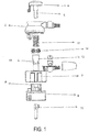
Fig. 2 . zeigt das Gesamterscheinungsbild des Auswerfsteckers. -
Fig. 3 . zeigt das Gesamterscheinungsbild der Feder. -
Fig. 4 . zeigt das Gesamterscheinungsbild des Druckstabs. -
Fig. 5 . zeigt das Gesamterscheinungsbild des Zahnrades. -
Fig. 6 . zeigt das Aussehen montierter Taste, Feder, Druckstab und Zahnrad -
Fig. 7 . zeigt das Aussehen montierter Taste, Feder, Druckstab, Zahnrad und Unterkörper -
Fig. 8 . zeigt das Aussehen montiertem Unterkörper -
Fig. 9 . zeigt das Schnittansicht von Taste, Feder, Druckstab, Zahnrad und Unterkörper -
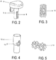
Fig. 10 . zeigt Ansicht vom Oberkörper -
Fig. 11 . zeigt Ansicht vom Zwischenkörper -
Fig. 12 . zeigt Ansicht vom Unterkörper -
Fig. 13 . zeigt das Gesamterscheinungsbild vom Auswerfstecker -
Fig. 14 . zeigt Schnittansicht vom Auswerfsteckers -
Fig.15 . zeigt das Gesamterscheinungsbild vom Auswerfstecker -
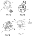
Fig. 16 . zeigt Ansicht von oben vom Auswerfstecker -
Fig. 17 . zeigt Ansicht von unten vom Auswerfstecker - Im Folgenden wird ein Ausführungsbeispiel der Erfindung beschrieben.
- Der Auswerferstecker hat einen oberen Körper (2), eine Taste (4), einen Zwischenkörper (7), einen unteren Körper (8), einen Stecker (1), eine Feder (11), einen Druckstab (12), ein Getriebe (14), eine Steckverbindung (15) und ein Stromkabel (16).
- Auswurfstecker (1): der obere Körper (2) hat in der Mitte eine obere Körperhöhle (3) für die Vorwärts- und Rückwärtsbewegung der Taste (4). Am oberen Körper (2) des Steckers (1) ist ein Haltekreis (17) so positioniert, dass er mit den Fingern leicht zu greifen ist.
- Der Stecker (1): die Taste (4) ist so positioniert, dass sie mit der oberen Körperhöhle (3) kompatibel ist. Die Unterseite der Taste (4) hat einen Tastenvorsprung (5). An dem Tastenvorsprung (5) ist eine Tastennut (6) mit Zähnen ausgebildet.
- Die Feder (11) ist so positioniert, dass der Druckstab (12) durch sie hindurchgeht, um nach dem Drücken der Taste (4) in ihre erste Position zu kommen. Die Feder (11) kann zwischen der Drucktaste (4) und einem Drucktastengehäuse (9) sowie dem Drucktastengehäuse positioniert werden. Zwei Zahnradgehäuse (13) befinden sich an dem Druckstab (12). Das Zahnrad (14) ist an dem Zahnradgehäuse (13) positioniert.
- Der Tastenvorsprung (5) führt durch den Druckstab (12). Die Tastennut (6) an dem Tastenvorsprung (5) berührt die Innenseite der Zahnräder (14) an dem Druckstab (12). Die Zahnräder (4) an dem, Druckstab (12) stehen mit dem inneren Teil der Tastennut (6) und der Nut (10) des unteren Körpers an der Innenseite des Druckstabgehäuses (9) in Kontakt. Der Druckstab (12) kann sich mit Hilfe der Zahnräder (14) auf dem Druckstabgehäuse (9) frei hin- und her bewegen.
- Das Druckstabgehäuse (9) ist am oberen Teil des unteren Körpers (8) positioniert, und Steckerstäbe (15) sind am unteren Teil positioniert. In der Mitte ist der untere Körperhohlraum (18) für den Durchtritt des Druckstabs (12) positioniert.
- Während der Stecker (1) an der Buchse befestigt ist und mit dem Daumen die Taste (4) gedrückt wird, wird der Stecker (1) vom Zeige - und Mittelfinger an der Haltekurve (17) umfasst. Wenn die Taste (4) gedrückt wird, dient der mit der Buchse in Kontakt stehende Druckstab (12) als Stütze und der Stecker (1) verlässt die Buchse.
- Das Stromkabel (16) ist in dem Spalt zwischen dem oberen Körper (2) und dem Zwischenkörper (7) positioniert.
- Es kann durch die Kombination der montierbaren Teile sowie auch in einer einzigen nicht montierbare Form die gleiche Funktion ausgeführt werden.
-
- 1. Auswerfstecker
- 2. Oberer Körper
- 3. Obere Körperhöhle
- 4. Taste
- 5. Tastenvorsprung
- 6. Tastennut
- 7. Zwischenkörper
- 8. Unterer Körper
- 9. Druckstabgehäuse
- 10. Nut des unteren Körpers
- 11. Feder
- 12. Druckstab
- 13. Zahnradgehäuse
- 14. Zahnrad
- 15. Steckerstäbe
- 16. Stromkabel
- 17. Haltekreis
- 18. Unter Körperhöhle
Claims (8)
- Auswerferstecker (1) mit einem oberen Körper (2), einer Taste (4), einem Zwischenkörper (7), einem unteren Körper (8), einer Feder (11), einem Druckstab (12), Steckerstäben (15) und einem Stromkabel (16),
dadurch gekennzeichnet, dass
an der Unterseite der Taste (4) ein Tastenvorsprung (5) vorhanden ist, an dem eine Tastennut (6) mit Zähnen positioniert ist,
der Druckstab (12) am unteren Teil der Taste (4) so positioniert ist, dass der Tastenvorsprung (5) eingepasst ist, und dass
zwei gegenüberliegende Zahnräder (14) an dem Druckstab (12) angeordnet sind und die Innenseite der Zahnräder (14) mit der Tastennut (6) in Eingriff ist und der äußere Abschnitt der Zahnräder (14) mit einer Nut (10) mit Zähnen des unteren Körpers in Eingriff ist, wobei
die Zahnräder (14), die Tastennut (6) und die Nut (10) ein Getriebe bilden. - Auswerferstecker (1) gemäß Anspruch 1, wobei sich in der Mitte des oberen Körpers (2) eine obere Körperhöhle (3) befindet.
- Auswerferstecker (1) gemäß Anspruch 1 oder 2, wobei an den äußeren Seiten des oberen Körpers (2) ein Haltekreis (17) positioniert ist.
- Auswerferstecker (1) gemäß Anspruch 2 oder den Ansprüchen 2 und 3, wobei sich die Taste (4) in der oberen Körperhöhle (3) befindet.
- Auswerferstecker (1) gemäß einem der vorherigen Ansprüche, wobei der Druckstab (12) innerhalb eines Druckstabgehäuses (9) auf dem unteren Körper (8) positioniert ist.
- Auswerferstecker (1) gemäß einem der vorherigen Ansprüche, wobei der Druckstab (12) durch die Feder (11) führt.
- Auswerferstecker (1) gemäß Anspruch 5 oder den Ansprüchen 5 und 6, wobei die Feder (11) zwischen der Taste (4) und dem Druckstabgehäuse (9) sowie innerhalb des Druckstabgehäuses (9) positioniert werden kann.
- Auswerferstecker (1) gemäß Anspruch 5, den Ansprüchen 5 und 6 oder Anspruch 7, wobei das Druckstabgehäuse (9) am oberen Teil des unteren Körpers (8) ausgebildet ist, die Steckerstäbe (15) am unteren Teil des unteren Körpers (8) ausgebildet sind, und eine untere Körperhöhle (18) in der Mitte des unteren Körpers (8) ausgebildet ist.
Applications Claiming Priority (1)
| Application Number | Priority Date | Filing Date | Title |
|---|---|---|---|
| TR201616753 | 2016-11-18 |
Publications (2)
| Publication Number | Publication Date |
|---|---|
| EP3324497A1 EP3324497A1 (de) | 2018-05-23 |
| EP3324497B1 true EP3324497B1 (de) | 2019-10-16 |
Family
ID=60452387
Family Applications (1)
| Application Number | Title | Priority Date | Filing Date |
|---|---|---|---|
| EP17202340.0A Not-in-force EP3324497B1 (de) | 2016-11-18 | 2017-11-17 | Abnehmbarer auswerferstecker |
Country Status (1)
| Country | Link |
|---|---|
| EP (1) | EP3324497B1 (de) |
Family Cites Families (5)
| Publication number | Priority date | Publication date | Assignee | Title |
|---|---|---|---|---|
| JPH0565077U (ja) * | 1992-02-05 | 1993-08-27 | アイワ株式会社 | 電源プラグ |
| JPH10312855A (ja) * | 1997-05-14 | 1998-11-24 | Shinji Ota | 電源プラグとその助力装置 |
| CN2836272Y (zh) * | 2005-11-10 | 2006-11-08 | 何芬 | 安装有顶杆的插头 |
| CN102064431A (zh) * | 2010-12-20 | 2011-05-18 | 卢明 | 可弹出插头及其制造方法 |
| SE537610C2 (sv) * | 2013-11-20 | 2015-07-28 | Eazyplug Ab | Elektrisk stickpropp |
-
2017
- 2017-11-17 EP EP17202340.0A patent/EP3324497B1/de not_active Not-in-force
Non-Patent Citations (1)
| Title |
|---|
| None * |
Also Published As
| Publication number | Publication date |
|---|---|
| EP3324497A1 (de) | 2018-05-23 |
Similar Documents
| Publication | Publication Date | Title |
|---|---|---|
| DE102009008108B4 (de) | Steckverbinder mit Betätigungshebel | |
| DE69405363T2 (de) | Verbinder mit elastischem Verriegelungselement | |
| EP0822776B1 (de) | Staubsauger mit einem motorgehäuse | |
| WO2010049197A1 (de) | Anschlussklemme zum anschluss von leiterenden | |
| DE112012002781T5 (de) | Hebelsteckverbinder | |
| DE60209409T2 (de) | Verriegelungseinrichtung für Verbinder | |
| DE69209834T2 (de) | Elektrische steckdose mit verbesserter trennchartakteristik | |
| EP3324497B1 (de) | Abnehmbarer auswerferstecker | |
| DE2907967C2 (de) | Elektrischer Stecker | |
| DE2931207C2 (de) | Einrichtung am Anschlußstück eines Saugschlauches für elektrisch betriebene Vorrichtungen | |
| DE102014101048A1 (de) | Steckverbindende Anschlussbaugruppe | |
| DE112012002788T5 (de) | Hebelsteckverbinder | |
| WO2013034443A1 (de) | Elektrischer verbinder mit berührschutz | |
| DE3736849C2 (de) | ||
| DE112011104484T5 (de) | Verbinder | |
| CN217641998U (zh) | 一种按压式省力插头及插座 | |
| CN115207704A (zh) | 一种按压式省力插头及插座 | |
| DE10351776B4 (de) | Schutzkontaktstecker mit Auswurfausrichtung | |
| DE202016101891U1 (de) | LED-Leitungsanschluss | |
| WO2020254389A1 (de) | Kaltgerätesteckerbuchse mit verriegelungselement, gehäusestecker und kaltgerät | |
| DE3101492A1 (de) | Schutzkontakt-stecker.- mit hebelfunktion | |
| DE678913C (de) | Elektrischer Stecker, bei dem die Steckerstifte durch Federkontakte eines Isolierkoerpers ersetzt sind | |
| DE19534725C2 (de) | Vorrichtung zum Sichern der Steckverbindung eines Elektrizitätszählers mit einer Zählersteckklemme | |
| DE625432C (de) | Gehaeuse fuer elektrischer Steckerkupplungen | |
| DE637131C (de) | Kupplungssteckdose aus Weichgummi |
Legal Events
| Date | Code | Title | Description |
|---|---|---|---|
| PUAI | Public reference made under article 153(3) epc to a published international application that has entered the european phase |
Free format text: ORIGINAL CODE: 0009012 |
|
| STAA | Information on the status of an ep patent application or granted ep patent |
Free format text: STATUS: THE APPLICATION HAS BEEN PUBLISHED |
|
| AK | Designated contracting states |
Kind code of ref document: A1 Designated state(s): AL AT BE BG CH CY CZ DE DK EE ES FI FR GB GR HR HU IE IS IT LI LT LU LV MC MK MT NL NO PL PT RO RS SE SI SK SM TR |
|
| AX | Request for extension of the european patent |
Extension state: BA ME |
|
| STAA | Information on the status of an ep patent application or granted ep patent |
Free format text: STATUS: REQUEST FOR EXAMINATION WAS MADE |
|
| 17P | Request for examination filed |
Effective date: 20181023 |
|
| RBV | Designated contracting states (corrected) |
Designated state(s): AL AT BE BG CH CY CZ DE DK EE ES FI FR GB GR HR HU IE IS IT LI LT LU LV MC MK MT NL NO PL PT RO RS SE SI SK SM TR |
|
| RIC1 | Information provided on ipc code assigned before grant |
Ipc: H01R 13/635 20060101AFI20190218BHEP Ipc: H01R 103/00 20060101ALN20190218BHEP |
|
| GRAP | Despatch of communication of intention to grant a patent |
Free format text: ORIGINAL CODE: EPIDOSNIGR1 |
|
| STAA | Information on the status of an ep patent application or granted ep patent |
Free format text: STATUS: GRANT OF PATENT IS INTENDED |
|
| INTG | Intention to grant announced |
Effective date: 20190430 |
|
| RAP1 | Party data changed (applicant data changed or rights of an application transferred) |
Owner name: XEARTH BILGISAYAR UZAY VE ROBOT TEKNOLOJILERI ARAS |
|
| RIN1 | Information on inventor provided before grant (corrected) |
Inventor name: MUSULLU, METIN |
|
| GRAS | Grant fee paid |
Free format text: ORIGINAL CODE: EPIDOSNIGR3 |
|
| GRAA | (expected) grant |
Free format text: ORIGINAL CODE: 0009210 |
|
| STAA | Information on the status of an ep patent application or granted ep patent |
Free format text: STATUS: THE PATENT HAS BEEN GRANTED |
|
| AK | Designated contracting states |
Kind code of ref document: B1 Designated state(s): AL AT BE BG CH CY CZ DE DK EE ES FI FR GB GR HR HU IE IS IT LI LT LU LV MC MK MT NL NO PL PT RO RS SE SI SK SM TR |
|
| REG | Reference to a national code |
Ref country code: GB Ref legal event code: FG4D Free format text: NOT ENGLISH |
|
| REG | Reference to a national code |
Ref country code: CH Ref legal event code: EP |
|
| REG | Reference to a national code |
Ref country code: DE Ref legal event code: R096 Ref document number: 502017002588 Country of ref document: DE |
|
| REG | Reference to a national code |
Ref country code: IE Ref legal event code: FG4D Free format text: LANGUAGE OF EP DOCUMENT: GERMAN |
|
| REG | Reference to a national code |
Ref country code: AT Ref legal event code: REF Ref document number: 1192204 Country of ref document: AT Kind code of ref document: T Effective date: 20191115 |
|
| REG | Reference to a national code |
Ref country code: NL Ref legal event code: MP Effective date: 20191016 |
|
| REG | Reference to a national code |
Ref country code: LT Ref legal event code: MG4D |
|
| PG25 | Lapsed in a contracting state [announced via postgrant information from national office to epo] |
Ref country code: BG Free format text: LAPSE BECAUSE OF FAILURE TO SUBMIT A TRANSLATION OF THE DESCRIPTION OR TO PAY THE FEE WITHIN THE PRESCRIBED TIME-LIMIT Effective date: 20200116 Ref country code: FI Free format text: LAPSE BECAUSE OF FAILURE TO SUBMIT A TRANSLATION OF THE DESCRIPTION OR TO PAY THE FEE WITHIN THE PRESCRIBED TIME-LIMIT Effective date: 20191016 Ref country code: PT Free format text: LAPSE BECAUSE OF FAILURE TO SUBMIT A TRANSLATION OF THE DESCRIPTION OR TO PAY THE FEE WITHIN THE PRESCRIBED TIME-LIMIT Effective date: 20200217 Ref country code: LV Free format text: LAPSE BECAUSE OF FAILURE TO SUBMIT A TRANSLATION OF THE DESCRIPTION OR TO PAY THE FEE WITHIN THE PRESCRIBED TIME-LIMIT Effective date: 20191016 Ref country code: SE Free format text: LAPSE BECAUSE OF FAILURE TO SUBMIT A TRANSLATION OF THE DESCRIPTION OR TO PAY THE FEE WITHIN THE PRESCRIBED TIME-LIMIT Effective date: 20191016 Ref country code: GR Free format text: LAPSE BECAUSE OF FAILURE TO SUBMIT A TRANSLATION OF THE DESCRIPTION OR TO PAY THE FEE WITHIN THE PRESCRIBED TIME-LIMIT Effective date: 20200117 Ref country code: NO Free format text: LAPSE BECAUSE OF FAILURE TO SUBMIT A TRANSLATION OF THE DESCRIPTION OR TO PAY THE FEE WITHIN THE PRESCRIBED TIME-LIMIT Effective date: 20200116 Ref country code: PL Free format text: LAPSE BECAUSE OF FAILURE TO SUBMIT A TRANSLATION OF THE DESCRIPTION OR TO PAY THE FEE WITHIN THE PRESCRIBED TIME-LIMIT Effective date: 20191016 Ref country code: LT Free format text: LAPSE BECAUSE OF FAILURE TO SUBMIT A TRANSLATION OF THE DESCRIPTION OR TO PAY THE FEE WITHIN THE PRESCRIBED TIME-LIMIT Effective date: 20191016 Ref country code: NL Free format text: LAPSE BECAUSE OF FAILURE TO SUBMIT A TRANSLATION OF THE DESCRIPTION OR TO PAY THE FEE WITHIN THE PRESCRIBED TIME-LIMIT Effective date: 20191016 |
|
| PG25 | Lapsed in a contracting state [announced via postgrant information from national office to epo] |
Ref country code: HR Free format text: LAPSE BECAUSE OF FAILURE TO SUBMIT A TRANSLATION OF THE DESCRIPTION OR TO PAY THE FEE WITHIN THE PRESCRIBED TIME-LIMIT Effective date: 20191016 Ref country code: IS Free format text: LAPSE BECAUSE OF FAILURE TO SUBMIT A TRANSLATION OF THE DESCRIPTION OR TO PAY THE FEE WITHIN THE PRESCRIBED TIME-LIMIT Effective date: 20200224 Ref country code: RS Free format text: LAPSE BECAUSE OF FAILURE TO SUBMIT A TRANSLATION OF THE DESCRIPTION OR TO PAY THE FEE WITHIN THE PRESCRIBED TIME-LIMIT Effective date: 20191016 |
|
| PG25 | Lapsed in a contracting state [announced via postgrant information from national office to epo] |
Ref country code: AL Free format text: LAPSE BECAUSE OF FAILURE TO SUBMIT A TRANSLATION OF THE DESCRIPTION OR TO PAY THE FEE WITHIN THE PRESCRIBED TIME-LIMIT Effective date: 20191016 |
|
| REG | Reference to a national code |
Ref country code: DE Ref legal event code: R097 Ref document number: 502017002588 Country of ref document: DE |
|
| PG2D | Information on lapse in contracting state deleted |
Ref country code: IS |
|
| PG25 | Lapsed in a contracting state [announced via postgrant information from national office to epo] |
Ref country code: EE Free format text: LAPSE BECAUSE OF FAILURE TO SUBMIT A TRANSLATION OF THE DESCRIPTION OR TO PAY THE FEE WITHIN THE PRESCRIBED TIME-LIMIT Effective date: 20191016 Ref country code: DK Free format text: LAPSE BECAUSE OF FAILURE TO SUBMIT A TRANSLATION OF THE DESCRIPTION OR TO PAY THE FEE WITHIN THE PRESCRIBED TIME-LIMIT Effective date: 20191016 Ref country code: ES Free format text: LAPSE BECAUSE OF FAILURE TO SUBMIT A TRANSLATION OF THE DESCRIPTION OR TO PAY THE FEE WITHIN THE PRESCRIBED TIME-LIMIT Effective date: 20191016 Ref country code: RO Free format text: LAPSE BECAUSE OF FAILURE TO SUBMIT A TRANSLATION OF THE DESCRIPTION OR TO PAY THE FEE WITHIN THE PRESCRIBED TIME-LIMIT Effective date: 20191016 Ref country code: LU Free format text: LAPSE BECAUSE OF NON-PAYMENT OF DUE FEES Effective date: 20191117 Ref country code: CZ Free format text: LAPSE BECAUSE OF FAILURE TO SUBMIT A TRANSLATION OF THE DESCRIPTION OR TO PAY THE FEE WITHIN THE PRESCRIBED TIME-LIMIT Effective date: 20191016 Ref country code: MC Free format text: LAPSE BECAUSE OF FAILURE TO SUBMIT A TRANSLATION OF THE DESCRIPTION OR TO PAY THE FEE WITHIN THE PRESCRIBED TIME-LIMIT Effective date: 20191016 Ref country code: IS Free format text: LAPSE BECAUSE OF FAILURE TO SUBMIT A TRANSLATION OF THE DESCRIPTION OR TO PAY THE FEE WITHIN THE PRESCRIBED TIME-LIMIT Effective date: 20200216 |
|
| PLBE | No opposition filed within time limit |
Free format text: ORIGINAL CODE: 0009261 |
|
| REG | Reference to a national code |
Ref country code: BE Ref legal event code: MM Effective date: 20191130 |
|
| STAA | Information on the status of an ep patent application or granted ep patent |
Free format text: STATUS: NO OPPOSITION FILED WITHIN TIME LIMIT |
|
| PG25 | Lapsed in a contracting state [announced via postgrant information from national office to epo] |
Ref country code: SM Free format text: LAPSE BECAUSE OF FAILURE TO SUBMIT A TRANSLATION OF THE DESCRIPTION OR TO PAY THE FEE WITHIN THE PRESCRIBED TIME-LIMIT Effective date: 20191016 Ref country code: IT Free format text: LAPSE BECAUSE OF FAILURE TO SUBMIT A TRANSLATION OF THE DESCRIPTION OR TO PAY THE FEE WITHIN THE PRESCRIBED TIME-LIMIT Effective date: 20191016 Ref country code: SK Free format text: LAPSE BECAUSE OF FAILURE TO SUBMIT A TRANSLATION OF THE DESCRIPTION OR TO PAY THE FEE WITHIN THE PRESCRIBED TIME-LIMIT Effective date: 20191016 |
|
| 26N | No opposition filed |
Effective date: 20200717 |
|
| PG25 | Lapsed in a contracting state [announced via postgrant information from national office to epo] |
Ref country code: IE Free format text: LAPSE BECAUSE OF NON-PAYMENT OF DUE FEES Effective date: 20191117 Ref country code: FR Free format text: LAPSE BECAUSE OF NON-PAYMENT OF DUE FEES Effective date: 20191216 |
|
| PG25 | Lapsed in a contracting state [announced via postgrant information from national office to epo] |
Ref country code: BE Free format text: LAPSE BECAUSE OF NON-PAYMENT OF DUE FEES Effective date: 20191130 Ref country code: SI Free format text: LAPSE BECAUSE OF FAILURE TO SUBMIT A TRANSLATION OF THE DESCRIPTION OR TO PAY THE FEE WITHIN THE PRESCRIBED TIME-LIMIT Effective date: 20191016 |
|
| PG25 | Lapsed in a contracting state [announced via postgrant information from national office to epo] |
Ref country code: CY Free format text: LAPSE BECAUSE OF FAILURE TO SUBMIT A TRANSLATION OF THE DESCRIPTION OR TO PAY THE FEE WITHIN THE PRESCRIBED TIME-LIMIT Effective date: 20191016 |
|
| REG | Reference to a national code |
Ref country code: CH Ref legal event code: PL |
|
| PG25 | Lapsed in a contracting state [announced via postgrant information from national office to epo] |
Ref country code: MT Free format text: LAPSE BECAUSE OF FAILURE TO SUBMIT A TRANSLATION OF THE DESCRIPTION OR TO PAY THE FEE WITHIN THE PRESCRIBED TIME-LIMIT Effective date: 20191016 Ref country code: HU Free format text: LAPSE BECAUSE OF FAILURE TO SUBMIT A TRANSLATION OF THE DESCRIPTION OR TO PAY THE FEE WITHIN THE PRESCRIBED TIME-LIMIT; INVALID AB INITIO Effective date: 20171117 |
|
| PG25 | Lapsed in a contracting state [announced via postgrant information from national office to epo] |
Ref country code: CH Free format text: LAPSE BECAUSE OF NON-PAYMENT OF DUE FEES Effective date: 20201130 Ref country code: LI Free format text: LAPSE BECAUSE OF NON-PAYMENT OF DUE FEES Effective date: 20201130 |
|
| PG25 | Lapsed in a contracting state [announced via postgrant information from national office to epo] |
Ref country code: MK Free format text: LAPSE BECAUSE OF FAILURE TO SUBMIT A TRANSLATION OF THE DESCRIPTION OR TO PAY THE FEE WITHIN THE PRESCRIBED TIME-LIMIT Effective date: 20191016 |
|
| GBPC | Gb: european patent ceased through non-payment of renewal fee |
Effective date: 20211117 |
|
| PG25 | Lapsed in a contracting state [announced via postgrant information from national office to epo] |
Ref country code: GB Free format text: LAPSE BECAUSE OF NON-PAYMENT OF DUE FEES Effective date: 20211117 |
|
| REG | Reference to a national code |
Ref country code: DE Ref legal event code: R082 Ref document number: 502017002588 Country of ref document: DE |
|
| PGFP | Annual fee paid to national office [announced via postgrant information from national office to epo] |
Ref country code: DE Payment date: 20230530 Year of fee payment: 6 |
|
| REG | Reference to a national code |
Ref country code: AT Ref legal event code: MM01 Ref document number: 1192204 Country of ref document: AT Kind code of ref document: T Effective date: 20221117 |
|
| PG25 | Lapsed in a contracting state [announced via postgrant information from national office to epo] |
Ref country code: AT Free format text: LAPSE BECAUSE OF NON-PAYMENT OF DUE FEES Effective date: 20221117 |
|
| REG | Reference to a national code |
Ref country code: DE Ref legal event code: R119 Ref document number: 502017002588 Country of ref document: DE |
|
| PG25 | Lapsed in a contracting state [announced via postgrant information from national office to epo] |
Ref country code: TR Free format text: LAPSE BECAUSE OF NON-PAYMENT OF DUE FEES Effective date: 20201117 |
|
| PG25 | Lapsed in a contracting state [announced via postgrant information from national office to epo] |
Ref country code: DE Free format text: LAPSE BECAUSE OF NON-PAYMENT OF DUE FEES Effective date: 20240601 |
|
| PG25 | Lapsed in a contracting state [announced via postgrant information from national office to epo] |
Ref country code: DE Free format text: LAPSE BECAUSE OF NON-PAYMENT OF DUE FEES Effective date: 20240601 |