EP3323649A1 - Scheibenkörper mit einem daran befestigten kunststoffrahmen für ein fahrzeug - Google Patents
Scheibenkörper mit einem daran befestigten kunststoffrahmen für ein fahrzeug Download PDFInfo
- Publication number
- EP3323649A1 EP3323649A1 EP17001794.1A EP17001794A EP3323649A1 EP 3323649 A1 EP3323649 A1 EP 3323649A1 EP 17001794 A EP17001794 A EP 17001794A EP 3323649 A1 EP3323649 A1 EP 3323649A1
- Authority
- EP
- European Patent Office
- Prior art keywords
- resin frame
- plate
- vehicle
- adhesive
- glass plate
- Prior art date
- Legal status (The legal status is an assumption and is not a legal conclusion. Google has not performed a legal analysis and makes no representation as to the accuracy of the status listed.)
- Granted
Links
- 229920005989 resin Polymers 0.000 title claims abstract description 120
- 239000011347 resin Substances 0.000 title claims abstract description 120
- 239000000853 adhesive Substances 0.000 claims abstract description 51
- 230000001070 adhesive effect Effects 0.000 claims abstract description 51
- 230000002093 peripheral effect Effects 0.000 claims abstract description 37
- XLYOFNOQVPJJNP-UHFFFAOYSA-N water Substances O XLYOFNOQVPJJNP-UHFFFAOYSA-N 0.000 claims description 15
- 239000011521 glass Substances 0.000 description 72
- 239000000463 material Substances 0.000 description 16
- 229920001971 elastomer Polymers 0.000 description 8
- 239000000806 elastomer Substances 0.000 description 5
- 238000000465 moulding Methods 0.000 description 5
- 229920003002 synthetic resin Polymers 0.000 description 5
- 239000000057 synthetic resin Substances 0.000 description 5
- 238000004519 manufacturing process Methods 0.000 description 3
- 229920002635 polyurethane Polymers 0.000 description 3
- 239000004814 polyurethane Substances 0.000 description 3
- 229920002943 EPDM rubber Polymers 0.000 description 2
- 238000002347 injection Methods 0.000 description 2
- 239000007924 injection Substances 0.000 description 2
- 239000000203 mixture Substances 0.000 description 2
- 238000012986 modification Methods 0.000 description 2
- 230000004048 modification Effects 0.000 description 2
- 229920002647 polyamide Polymers 0.000 description 2
- 229920000728 polyester Polymers 0.000 description 2
- 239000004709 Chlorinated polyethylene Substances 0.000 description 1
- 229920001651 Cyanoacrylate Polymers 0.000 description 1
- 239000004593 Epoxy Substances 0.000 description 1
- MWCLLHOVUTZFKS-UHFFFAOYSA-N Methyl cyanoacrylate Chemical compound COC(=O)C(=C)C#N MWCLLHOVUTZFKS-UHFFFAOYSA-N 0.000 description 1
- ISWSIDIOOBJBQZ-UHFFFAOYSA-N Phenol Chemical compound OC1=CC=CC=C1 ISWSIDIOOBJBQZ-UHFFFAOYSA-N 0.000 description 1
- 239000004793 Polystyrene Substances 0.000 description 1
- XTXRWKRVRITETP-UHFFFAOYSA-N Vinyl acetate Chemical compound CC(=O)OC=C XTXRWKRVRITETP-UHFFFAOYSA-N 0.000 description 1
- 239000003522 acrylic cement Substances 0.000 description 1
- 239000000839 emulsion Substances 0.000 description 1
- 239000005038 ethylene vinyl acetate Substances 0.000 description 1
- 239000012530 fluid Substances 0.000 description 1
- 238000001746 injection moulding Methods 0.000 description 1
- 239000005340 laminated glass Substances 0.000 description 1
- 238000000034 method Methods 0.000 description 1
- 229920001200 poly(ethylene-vinyl acetate) Polymers 0.000 description 1
- 239000004417 polycarbonate Substances 0.000 description 1
- 229920000515 polycarbonate Polymers 0.000 description 1
- 229920000098 polyolefin Polymers 0.000 description 1
- 229920002223 polystyrene Polymers 0.000 description 1
- 239000004800 polyvinyl chloride Substances 0.000 description 1
- 229920000915 polyvinyl chloride Polymers 0.000 description 1
- 239000002904 solvent Substances 0.000 description 1
- 239000005341 toughened glass Substances 0.000 description 1
Images


Classifications
-
- B—PERFORMING OPERATIONS; TRANSPORTING
- B60—VEHICLES IN GENERAL
- B60J—WINDOWS, WINDSCREENS, NON-FIXED ROOFS, DOORS, OR SIMILAR DEVICES FOR VEHICLES; REMOVABLE EXTERNAL PROTECTIVE COVERINGS SPECIALLY ADAPTED FOR VEHICLES
- B60J1/00—Windows; Windscreens; Accessories therefor
- B60J1/004—Mounting of windows
- B60J1/007—Mounting of windows received in frames to be attached to vehicle
-
- B—PERFORMING OPERATIONS; TRANSPORTING
- B60—VEHICLES IN GENERAL
- B60J—WINDOWS, WINDSCREENS, NON-FIXED ROOFS, DOORS, OR SIMILAR DEVICES FOR VEHICLES; REMOVABLE EXTERNAL PROTECTIVE COVERINGS SPECIALLY ADAPTED FOR VEHICLES
- B60J10/00—Sealing arrangements
- B60J10/15—Sealing arrangements characterised by the material
-
- B—PERFORMING OPERATIONS; TRANSPORTING
- B60—VEHICLES IN GENERAL
- B60J—WINDOWS, WINDSCREENS, NON-FIXED ROOFS, DOORS, OR SIMILAR DEVICES FOR VEHICLES; REMOVABLE EXTERNAL PROTECTIVE COVERINGS SPECIALLY ADAPTED FOR VEHICLES
- B60J10/00—Sealing arrangements
- B60J10/70—Sealing arrangements specially adapted for windows or windscreens
-
- B—PERFORMING OPERATIONS; TRANSPORTING
- B29—WORKING OF PLASTICS; WORKING OF SUBSTANCES IN A PLASTIC STATE IN GENERAL
- B29C—SHAPING OR JOINING OF PLASTICS; SHAPING OF MATERIAL IN A PLASTIC STATE, NOT OTHERWISE PROVIDED FOR; AFTER-TREATMENT OF THE SHAPED PRODUCTS, e.g. REPAIRING
- B29C45/00—Injection moulding, i.e. forcing the required volume of moulding material through a nozzle into a closed mould; Apparatus therefor
- B29C45/14—Injection moulding, i.e. forcing the required volume of moulding material through a nozzle into a closed mould; Apparatus therefor incorporating preformed parts or layers, e.g. injection moulding around inserts or for coating articles
- B29C45/14311—Injection moulding, i.e. forcing the required volume of moulding material through a nozzle into a closed mould; Apparatus therefor incorporating preformed parts or layers, e.g. injection moulding around inserts or for coating articles using means for bonding the coating to the articles
-
- B—PERFORMING OPERATIONS; TRANSPORTING
- B29—WORKING OF PLASTICS; WORKING OF SUBSTANCES IN A PLASTIC STATE IN GENERAL
- B29C—SHAPING OR JOINING OF PLASTICS; SHAPING OF MATERIAL IN A PLASTIC STATE, NOT OTHERWISE PROVIDED FOR; AFTER-TREATMENT OF THE SHAPED PRODUCTS, e.g. REPAIRING
- B29C45/00—Injection moulding, i.e. forcing the required volume of moulding material through a nozzle into a closed mould; Apparatus therefor
- B29C45/17—Component parts, details or accessories; Auxiliary operations
- B29C45/26—Moulds
- B29C45/33—Moulds having transversely, e.g. radially, movable mould parts
-
- B—PERFORMING OPERATIONS; TRANSPORTING
- B29—WORKING OF PLASTICS; WORKING OF SUBSTANCES IN A PLASTIC STATE IN GENERAL
- B29C—SHAPING OR JOINING OF PLASTICS; SHAPING OF MATERIAL IN A PLASTIC STATE, NOT OTHERWISE PROVIDED FOR; AFTER-TREATMENT OF THE SHAPED PRODUCTS, e.g. REPAIRING
- B29C45/00—Injection moulding, i.e. forcing the required volume of moulding material through a nozzle into a closed mould; Apparatus therefor
- B29C45/17—Component parts, details or accessories; Auxiliary operations
- B29C45/40—Removing or ejecting moulded articles
- B29C45/44—Removing or ejecting moulded articles for undercut articles
-
- B—PERFORMING OPERATIONS; TRANSPORTING
- B32—LAYERED PRODUCTS
- B32B—LAYERED PRODUCTS, i.e. PRODUCTS BUILT-UP OF STRATA OF FLAT OR NON-FLAT, e.g. CELLULAR OR HONEYCOMB, FORM
- B32B37/00—Methods or apparatus for laminating, e.g. by curing or by ultrasonic bonding
- B32B37/12—Methods or apparatus for laminating, e.g. by curing or by ultrasonic bonding characterised by using adhesives
- B32B37/1284—Application of adhesive
-
- B—PERFORMING OPERATIONS; TRANSPORTING
- B60—VEHICLES IN GENERAL
- B60J—WINDOWS, WINDSCREENS, NON-FIXED ROOFS, DOORS, OR SIMILAR DEVICES FOR VEHICLES; REMOVABLE EXTERNAL PROTECTIVE COVERINGS SPECIALLY ADAPTED FOR VEHICLES
- B60J1/00—Windows; Windscreens; Accessories therefor
- B60J1/08—Windows; Windscreens; Accessories therefor arranged at vehicle sides
- B60J1/10—Windows; Windscreens; Accessories therefor arranged at vehicle sides fixedly mounted
-
- B—PERFORMING OPERATIONS; TRANSPORTING
- B32—LAYERED PRODUCTS
- B32B—LAYERED PRODUCTS, i.e. PRODUCTS BUILT-UP OF STRATA OF FLAT OR NON-FLAT, e.g. CELLULAR OR HONEYCOMB, FORM
- B32B37/00—Methods or apparatus for laminating, e.g. by curing or by ultrasonic bonding
- B32B37/14—Methods or apparatus for laminating, e.g. by curing or by ultrasonic bonding characterised by the properties of the layers
- B32B37/142—Laminating of sheets, panels or inserts, e.g. stiffeners, by wrapping in at least one outer layer, or inserting into a preformed pocket
Definitions
- the present invention relates to a plate-like body with a resin frame attached thereto for a vehicle.
- a glass plate for a window When a glass plate for a window is mounted into an opening of a vehicle, such as an automobile, it is usual to use a plate-like body with a resin frame attached thereto for a vehicle, wherein a glass plate as the plate-like body has a resin frame attached to a peripheral edge area.
- the resin frame prevents water, such as rain water, from entering the car-interior side of a vehicle.
- JP-A-H05-213057 discloses a process for applying an adhesive to the entire peripheral edge area of a glass plate, using a mold with a cavity space to clamp the peripheral edge area of the glass plate with the adhesive applied thereto, and injecting a resin material into the cavity space to produce a glass plate with the resin frame integrally molded thereto.
- the mold is opened to take out the glass plate with the resin frame integrally molded thereto from the mold. Because the configuration of the resin frame has been recently made complicated, the resin frame tends to have a great mold release resistance during demolding when the resin frame has a plurality of portions obliquely projecting into the cavity space for example.
- the resin frame When the mold is opened to demold the resin frame, the resin frame is pulled toward a demolding direction by the mold with the result that the resin frame could detach from an adhesive.
- the resin frame When a resin having a low green strength is used to mold the resin frame, the resin frame is likely to detach from an adhesive.
- an attempt is made to extend the time for curing the resin material during molding of the resin frame in order to prevent the resin frame from being detached from an adhesive it causes a reduction in throughput.
- the present invention is proposed in consideration of these problems. It is an object of the present invention to provide, without causing a reduction in throughput, a plate-like body for a vehicle, to which a resin frame formed in a complicated shape is attached.
- a plate-like body with a resin frame attached thereto for a vehicle which includes a plate-like body having two main surfaces and an end part connecting the two main surfaces, and a resin frame integrally molded to a peripheral edge area of the plate-like body; the resin frame including a main part having a plurality of inner surfaces facing the two main surfaces and the end part, and a plurality of projections obliquely projecting from the main part in a direction opposite to the plate-like body; and the resin frame having no adhesive between the peripheral edge area and an inner surface close to the projections.
- Fig. 1 is a plan view of a plate-like body with a resin frame attached thereto for a vehicle 10 according to the present invention.
- Fig. 2 is cross-sectional view of the plate-like body according to a first embodiment of the present invention taken along line A-A of Fig. 1
- Fig. 3 is cross-sectional view of the plate-like body taken along line B-B of Fig. 1
- Fig. 4 is cross-sectional view of the plate-like body taken along line C-C of Fig. 1 .
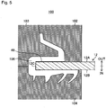
- Fig. 5 is a schematic cross-sectional view of essential parts of a mold usable in a device for producing a glass plate with a resin frame attached thereto.
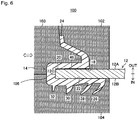
- Fig. 6 is a schematic cross-sectional view showing the essential parts of the mold when a resin material has been injected into the mold.
- the present invention will described about a case where the plate-like body 10 with a resin frame attached thereto for a vehicle is a glass plate. Since the plate-like body is a glass plate, this type of the plate-like body will be called a glass plate with a resin frame attached thereto for a vehicle in the following explanation. In a case where the plate-like body is a synthetic resin plate-like body, explanation of the embodiments are applicable to the case by understanding the embodiments with the glass plate being replaced by a synthetic resin plate-like body.
- the glass plate with a resin frame attached thereto for a vehicle 10 includes a glass plate 12 formed in a substantially trapezoidal shape as seen in a plan view, and a resin frame 14 attached to a peripheral edge area of the glass plate 12.
- an arrow UP indicates an upward direction in a vertical direction of a vehicle
- an arrow DOWN indicates a downward direction of the vertical direction.
- An arrow IN indicates a car-interior side of the vehicle
- an arrow OUT indicates a car-exterior side of the vehicle.
- the glass plate with a resin frame attached thereto for a vehicle 10 includes the glass plate 12 having two opposed main surfaces 12A and 12B, and an end part 12C connecting the two main surfaces 12A and 12B.
- the glass plate with a resin frame attached thereto for a vehicle 10 includes the resin frame 14 integrally molded to the peripheral edge area of the glass plate 12.
- the resin frame 14 has a main part 16 formed with three inner surfaces 18, 20 and 22 facing the two main surfaces 12A and 12B, and the end part 12C.
- the resin frame 14 is a so-called three-surface molding such that the inner surface 18 of the main part 16 faces the main surface 12A, the inner surface 22 of the main part 16 faces the main surface 12B and the inner surface 20 of the main part 16 faces the end part 12C.
- the main surface 12A is positioned on a car-exterior side while the main surface 12B is positioned on a car-interior side.
- the main part 16 of the resin frame 14 has a first projection 24 projecting from a side thereof close to the main surface 12A (car-exterior side).
- the main part 16 of the resin frame 14 also has second projections 26, 28, 30 and 32 projecting from a side thereof close to the main surface12B (car-interior side).
- the resin frame 14 has the main part 16, and a plurality of projections including the first projection 24 and the second projections 26, 28, 30 and 32.
- the first projection 24 and the second projections 26, 28, 30 and 32 are called lips in some cases.
- the first projection 24 is fit into, e.g. a window frame of the vehicle and is elastically deformed by the window frame to close the spacing between the glass plate 12 and the window frame.
- the second projections 26, 28, 30 and 32 project toward the car-interior side to close, e.g. the spacing between the glass plate 12 and an interior member.
- the first projection 24 is formed to project so as to be curved in a substantially C-character shape as seen in cross-section.
- the C-character shape as seen in cross-section means that a spacing is formed in an inner concave side, as in e.g. a C-character shape, a substantially C-character shape, a substantially U-character shape or a substantially V-character shape.
- the second projections 26 and 28 are formed to obliquely projecting in a direction opposite to the glass plate 12 as seen in cross-section. It is usual that the second projections 26 and 28 having such a configuration are formed in a curved shape as a whole or are formed so as to have a bent leading edge.
- the second projections 26 and 28 have such a configuration, water, such as rain water, is prevented from running on an outer side of the resin frame 14 to enter the car-interior side.
- the second projections obliquely projecting in the direction opposite to the glass plate 12 are two projections 26 and 28, the second projections may be more than two.
- the second projections are more than two.
- the second projection 30 is formed in a substantially fan shape in cross-section while the second projection 32 is formed in a substantially trapezoidal shape in cross-section.
- the first projection 24 and the second projections 26, 28, 30 and 32 have different shapes so as to be matched to the configuration of a vehicle window frame, to which the glass plate is mounted.
- the second projections 26 and 28 trend to have a greater mold release resistance because of obliquely projecting in the direction opposite to the glass plate 12 in cross-section. This cross sectional shape results in difficulty in releasing the second projections 26 and 28 from a mold 100 (see Figs. 5 and 6 ) as described later.
- the glass plate with a resin frame attached thereto for a vehicle 10 has no adhesive applied thereon between the peripheral edge area of the main surface12B and the inner surface 22 of the main part 16 with the second projections 26, 28, 30 and 32 in order to provide, without causing a reduction in throughput, a plate-like body to which the resin frame 14 formed in a complicated shape is attached.
- the main part 16 has the plural inner surfaces 18 and 20 in addition to the inner surface 22 without an adhesive being applied thereto.
- the main part has an adhesive 26 applied thereon only between the peripheral edge area of the main surface 12A and the inner surface 18 as one of the plural inner surfaces 18 and 20.
- the main part may have no adhesive applied thereon between the end part 12C and the inner surface 20.
- the main part 16 has a plurality of projections formed thereon such that the projections include a first projection 34 projecting from a side close to the main surface 12A, a second projection 36 projecting from a side close to the main surface 12B, and third projections 38 projecting from a side close to the end part 12C.
- the first projection 34 is formed in an arc shape in cross-section.
- the second projection 36 is also formed in an arc shape in cross-section.
- the third projections 38 are formed in a substantially rectangular shape in cross-section.
- the main part has no adhesive applied thereon between the inner surface 22 close to the second projection 36 and the peripheral edge area of the main surface 12B.
- the main part has an adhesive 46 applied thereon only between the inner surface 18 close to the first projection 34 and the peripheral edge area of the main surface 12A.
- the main part 16 as a plurality of projections formed thereon such that the projections include a first projection 40 projecting from a side close to a main surface 12A, a second projection 42 projecting from a side close to the main surface 12B and a third projection 44 projecting from a side close to the end part 12C.
- the main part has no adhesive applied thereon between the inner surface 22 close to a second projection 42 and the peripheral edge area of the main surface 12B.
- the main part has the adhesive 46 applied thereon only between the inner surface 18 close to the first projection 40 and the peripheral edge area of the main surface 12A.
- the first projection 40 is formed in a substantially C character shape in cross-section
- the second projection 42 is also formed in a substantially C character shape in cross-section.
- the second projections 26, 28, 30, 32, 36 and 42 project towards the car-interior side. For this reason, the inner surface 22 of the main part 16 close to the second projections 26, 28, 30, 32, 36 and 42 is visible from the car-exterior side in some cases.
- an adhesive is applied between the inner surface 22 and the peripheral edge area of the main surface 12B, if the resin frame 14 is partly detached from the adhesive, a detached part and a non-detached part are recognized as an unintentional pattern, which is not preferred in terms of appearance.
- the glass plate 12 is formed in a substantially trapezoidal shape as seen in a plan view, there is no limitation to the shape.
- the glass plate 12 may be flat or curved.
- the plate-like body may be in the form of laminated glass, tempered glass and a double-glazed unit in addition to a glass plate as a single plate.
- the plate-like body may be a plate-like body made of a synthetic resin, or a laminated plate with a plate-like body made of a synthetic resin and a glass plate combined therein.
- a plate-like body made of a transparent organic resin material, such as polycarbonate, polystyrene, or poly-methylmethacrelate, or a laminate having at least two sheets made of at least one of these resins is applicable to the plate-like body made of a synthetic resin.
- the vehicle include an automobile and an electric railway car.
- a plate-like body is applicable to a window for a vehicle, such as a rear window, a windshield, a roof window, a sidelite, a side door window, an opera window, a rear quarter window, or a front bench window.
- the resin frame 14 collectively means a gasket, a molding, a weather strip, a seal rubber and so on attached around a plate-like body.
- soft polyvinyl chloride is generally used as the resin material for forming the resin frame.
- An elastomer such as a polyolefin-based elastomer, a polyurethane-based elastomer, a polyester-based elastomer or a polyamide-based elastomer, polyurethane, an ethylene-vinyl acetate copolymer, vinyl acetate, chlorinated polyethylene, ethylene-propylene-diene-terpolymer (EPDM) and other rubber material may be used. As needed, a mixture of at least two kinds of these materials may be used.
- the adhesive 46 may be a mixture of at least one or more selected from a polyurethane-based adhesive, a polyester-based adhesive, a polyamide-based adhesive, a phenol-based adhesive, an acrylic adhesive, an epoxy-based adhesive, a cyanoacrylate-based adhesive, a rubber-based adhesive and so on.
- the adhesive may be used as it is, or used, being dissolved in a solvent.
- the adhesive may be used as in an emulsion state to be dispersed in water.
- the resin frame 14 is mounted to the entire peripheral edge area of the glass plate 12, the resin frame may be mounted to the peripheral edge area so as to be discontinuous.
- the resin frame 14 has different cross-sectional shapes at the respective sides of the glass plate 12 in this embodiment as shown in Fig. 2 to Fig. 4 , the resin frame 14 may have the same cross-sectional shape as one another at all sides of the glass plate.
- the peripheral edge area of the glass plate 12 means an area that ranges from the end part 12C of the glass plate 12 to a position apart therefrom by a certain distance.
- Fig. 5 is a schematic cross-sectional view of essential parts of the mold 100 as a device for producing the glass plate with a resin frame attached thereto for a vehicle 10.
- the mold 100 includes dies 102 and 103 as top dies, and a die 104 as a bottom die.
- the space defined by these dies 102, 103 and 104 forms a cavity space 106.
- the glass plate 12 is sandwiched between the die 102 and the die 104 at the peripheral edge area such that the cavity space 106 is formed between the dies 102 and 103, the die 104 and the peripheral edge area of the glass plate 12.
- the adhesive 46 is not applied on the main surface 12B of the glass plate 12 which is close to the second projections 26 and 28 obliquely projecting in a direction opposite to the glass plate 12 from the main part 16 (see Fig. 2 ).
- the adhesive 46 is applied only on a part of the peripheral edge area of the main surface 12A of the glass plate 12 close to the first projection 24.
- the resin material is injected in a molten state into the cavity space 106 from an injection port (not shown) to be filled in the cavity space 106.
- the mold 100 is held under a certain pressure until the resin material is cured after the resin material is injected into the cavity space 106 of the mold 100.
- the mold 100 is opened, and the dies 102 and 103 and the die 104 are moved in a demolding direction.
- the first projections 24 extends toward the dies 102 and 103, being formed in a substantially C-shape in cross-section.
- the die 103 is configured so as to be slidable forward and backward directions as shown by an arrow. For this reason, when the first projection 24 is released from the mold 100, the resin frame is subjected to a low mold-releasing resistance.
- the backward movement means a movement in a direction to be apart from the resin frame 14.
- the dies 102 and 103 are moved, the first projection 24 is hardly pulled.
- the inner surface 18 of the main part 16 is not detached from the adhesive 46 with the result that the resin frame 14 is not detached from the adhesive 46.
- the second projections 26 and 28 obliquely project from the main part 16 toward the die 104 in a direction opposite to the glass plate 12. It is difficult to use a slidable mold for the second projections 26 and 28 having such a configuration. In many cases, the second projections 26 and 28 having such a configuration are entirely curved or have a bent leading end in order to water, such as rain water, from running on the car-exterior side of the resin frame 14 to enter the car-interior side. Even in a case where the die 104 is obliquely slid, leading edges of the second projections 26 and 28 generate mold-releasing resistance.
- the resin frame 14 causes the main part 16 to elastically return to a position to be brought into contact with the main surface 12B of the glass plate 12.
- the adhesive 46 is disposed between the inner surface 18 of the main part 16 of the resin frame 14 and the peripheral edge area of the main surface 12A of the glass plate 12.
- the presence of the adhesive 46 prevents water, such as rain water, from entering from the car-exterior side into the car-interior side. It is preferred that the adhesive 46 be disposed between the inner surface 18 of the main part 16 and a part of the peripheral edge area of the main surface 12A facing the car-exterior side. It is because rain water or other water enters from the car-exterior side.
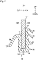
- the plate-like body with a resin frame attached thereto for a vehicle according to a second embodiment of the present invention will be described in reference to Figs. 7 to 10 . Similar elements to the elements of the plate-like body with a resin frame attached thereto for a vehicle according to the first embodiment will be denoted by similar reference numerals, and explanation on these elements will be omitted in some cases.
- the resin frame 14 according to the second embodiment is formed in a similar shape in cross-section to the shape of the first embodiment shown in Figs. 2 to 4 .
- the resin frame 14 according to the second embodiment has no adhesive disposed between the inner surface 22 of the resin frame 14 and the peripheral edge area of the main surface 12B as in the first embodiment.
- the second embodiment is different from the first embodiment in that no adhesive is disposed between the inner surface 18 and the main surface 12A and between the inner surface 20 and the end part 12C as shown in Fig. 7 .
- the second embodiment is carried out such that the glass plate 12 has a peripheral edge area sandwiched between a die 102 and the die 104 as in the first embodiment. Between the die 102, a die 103, the die 104 and the peripheral edge area of the glass plate 12, a cavity space 106 is formed.
- the second embodiment is carried out such that no adhesive is applied on the peripheral edge area of the glass plate 12, which is different from the first embodiment. For this reason, it is possible to have further improved throughput in comparison with the first embodiment since there is no step of applying an adhesive.
- a resin material is injected in a molten state into the cavity space 106 from an injection port (not shown) to be filled in the cavity space 106.
- a mold 100 molding the dies 102, 103 and 104 is held under a certain pressure until the resin material is cured after the resin material is injected into the cavity space 106 of the mold 100.
- the mold 100 is opened to release the glass plate with a resin frame attached thereto for a vehicle 10 from the mold 100 as in the first embodiment.
- the resin frame 14 have a drain hole 50 formed therein to discharge such fluid outside.
- the drain hole 50 be disposed at at least one location in the inner surface 20 of a part of the main body 16 situated at a lower position as shown in Fig. 10 when the glass plate with a resin frame attached thereto for a vehicle 10 is mounted to an opening of a vehicle.
- the drain hole 50 may include a plurality of cylindrical holes or an elongated continuous hole.
- the location of the drain hole 50 in the resin frame 14 may be properly determined, depending on the shape of the glass plate 12 of the glass plate with a resin frame attached thereto for a vehicle 10.
- the drain hole 50 may be disposed at any location in the resin frame 14 so long as the drain hole 50 has an opening close to the glass plate 12 situated at a higher position than the opening remote from the glass plate 12.
Landscapes
- Engineering & Computer Science (AREA)
- Mechanical Engineering (AREA)
- Manufacturing & Machinery (AREA)
- Injection Moulding Of Plastics Or The Like (AREA)
- Securing Of Glass Panes Or The Like (AREA)
- Seal Device For Vehicle (AREA)
- Body Structure For Vehicles (AREA)
Applications Claiming Priority (1)
| Application Number | Priority Date | Filing Date | Title |
|---|---|---|---|
| JP2016224118A JP6770683B2 (ja) | 2016-11-17 | 2016-11-17 | 車両用樹脂製枠体付き板状体 |
Publications (2)
| Publication Number | Publication Date |
|---|---|
| EP3323649A1 true EP3323649A1 (de) | 2018-05-23 |
| EP3323649B1 EP3323649B1 (de) | 2022-02-23 |
Family
ID=60269591
Family Applications (1)
| Application Number | Title | Priority Date | Filing Date |
|---|---|---|---|
| EP17001794.1A Active EP3323649B1 (de) | 2016-11-17 | 2017-11-02 | Scheibenkörper mit einem daran befestigten kunststoffrahmen für ein fahrzeug |
Country Status (4)
| Country | Link |
|---|---|
| US (1) | US10369868B2 (de) |
| EP (1) | EP3323649B1 (de) |
| JP (1) | JP6770683B2 (de) |
| CN (1) | CN108068596B (de) |
Families Citing this family (5)
| Publication number | Priority date | Publication date | Assignee | Title |
|---|---|---|---|---|
| JP6770683B2 (ja) * | 2016-11-17 | 2020-10-21 | Agc株式会社 | 車両用樹脂製枠体付き板状体 |
| CN106945493B (zh) * | 2017-03-14 | 2019-10-18 | 福耀玻璃工业集团股份有限公司 | 一种车窗玻璃的包边总成 |
| JPWO2020044705A1 (ja) * | 2018-08-27 | 2021-08-26 | 株式会社小糸製作所 | 車両用の樹脂製窓部材および車両用の樹脂製複合モジュール |
| DE102019126860A1 (de) * | 2019-10-07 | 2021-04-08 | Webasto SE | Deckel zum Verschließen einer Öffnung in einer Fahrzeugkarosserie |
| JP7435218B2 (ja) | 2020-04-30 | 2024-02-21 | マツダ株式会社 | 固定窓、および当該固定窓を備えた車両用ドア |
Citations (6)
| Publication number | Priority date | Publication date | Assignee | Title |
|---|---|---|---|---|
| JPS61129321A (ja) * | 1984-11-28 | 1986-06-17 | Shiraki Kinzoku Kogyo Kk | ウインドモ−ルデイング |
| DE3518145A1 (de) * | 1985-05-21 | 1986-11-27 | Elkamet-Werk Lahn-Kunststoff GmbH, 7100 Heilbronn | Fensterscheibe insbesondere fuer fahrzeuge |
| JPH05213057A (ja) | 1992-01-31 | 1993-08-24 | Asahi Glass Co Ltd | モール付き板状体の製造方法 |
| JPH0740381A (ja) * | 1993-07-28 | 1995-02-10 | Asahi Glass Co Ltd | 車両用枠体付き窓体の製造方法 |
| US6134851A (en) * | 1996-12-30 | 2000-10-24 | Saint-Gobain Vitrage | Encapsulated window and manufacturing process |
| CN2478825Y (zh) * | 2001-04-20 | 2002-02-27 | 秦荣华 | 一种车船用玻璃的包边结构 |
Family Cites Families (18)
| Publication number | Priority date | Publication date | Assignee | Title |
|---|---|---|---|---|
| DE19721566B4 (de) * | 1996-06-04 | 2014-08-28 | Volkswagen Ag | Verfahren zur Herstellung eines Scheibenkörpers mit einem durch Umspritzung angeformten Rahmen aus weichelastischem Material |
| DE19961706B4 (de) * | 1999-12-21 | 2004-09-09 | Saint-Gobain Sekurit Deutschland Gmbh & Co. Kg | Verbindung einer Fahrzeugscheibe mit einem angrenzenden Bauteil |
| DE20321018U1 (de) * | 2002-10-09 | 2005-08-11 | Metzeler Automotive Profile Systems Gmbh | Dichtungsprofil mit Zierleiste |
| US7210729B2 (en) * | 2004-06-30 | 2007-05-01 | Green Tokai Co., Ltd. | Windshield gasket design |
| JP4277920B2 (ja) * | 2007-05-25 | 2009-06-10 | トヨタ自動車株式会社 | ウェザストリップ構造 |
| JP5136193B2 (ja) * | 2008-05-12 | 2013-02-06 | セントラル硝子株式会社 | 枠体付きガラスの射出成形用金型および枠体付きガラスの製造方法 |
| DE202011000804U1 (de) * | 2011-04-06 | 2012-07-09 | Richard Fritz Gmbh + Co. Kg | Scheibeneinheit für Fenster an Kraftfahrzeugen |
| EP2740590B1 (de) * | 2011-08-05 | 2021-03-31 | Mitsubishi Engineering-Plastics Corporation | Platte und platteninstallationsstruktur |
| WO2013151071A1 (ja) * | 2012-04-06 | 2013-10-10 | 旭硝子株式会社 | 樹脂枠体付き板状体及び樹脂枠体付き板状体の製造方法 |
| WO2014034220A1 (ja) * | 2012-08-31 | 2014-03-06 | 本田技研工業株式会社 | 車両用ドア |
| US10023029B2 (en) * | 2012-08-31 | 2018-07-17 | Honda Motor Co., Ltd. | Vehicle door |
| WO2014034232A1 (ja) * | 2012-08-31 | 2014-03-06 | 本田技研工業株式会社 | モール付きガーニッシュ及び同搭載車両用ドア |
| JP5806699B2 (ja) * | 2013-04-11 | 2015-11-10 | 東海興業株式会社 | 成形品 |
| JP2015048029A (ja) * | 2013-09-04 | 2015-03-16 | 東海興業株式会社 | 車両用モールディングおよびその製造方法 |
| CN103538451B (zh) * | 2013-11-04 | 2016-06-01 | 上汽通用五菱汽车股份有限公司 | 汽车推拉窗胶条 |
| US9216633B2 (en) * | 2014-01-13 | 2015-12-22 | GM Global Technology Operations LLC | Close-out seal |
| JP6295145B2 (ja) * | 2014-05-30 | 2018-03-14 | 東海興業株式会社 | ピラーガーニッシュおよびその取り付け構造 |
| JP6770683B2 (ja) * | 2016-11-17 | 2020-10-21 | Agc株式会社 | 車両用樹脂製枠体付き板状体 |
-
2016
- 2016-11-17 JP JP2016224118A patent/JP6770683B2/ja active Active
-
2017
- 2017-10-31 US US15/799,127 patent/US10369868B2/en active Active
- 2017-11-02 EP EP17001794.1A patent/EP3323649B1/de active Active
- 2017-11-17 CN CN201711144616.6A patent/CN108068596B/zh active Active
Patent Citations (6)
| Publication number | Priority date | Publication date | Assignee | Title |
|---|---|---|---|---|
| JPS61129321A (ja) * | 1984-11-28 | 1986-06-17 | Shiraki Kinzoku Kogyo Kk | ウインドモ−ルデイング |
| DE3518145A1 (de) * | 1985-05-21 | 1986-11-27 | Elkamet-Werk Lahn-Kunststoff GmbH, 7100 Heilbronn | Fensterscheibe insbesondere fuer fahrzeuge |
| JPH05213057A (ja) | 1992-01-31 | 1993-08-24 | Asahi Glass Co Ltd | モール付き板状体の製造方法 |
| JPH0740381A (ja) * | 1993-07-28 | 1995-02-10 | Asahi Glass Co Ltd | 車両用枠体付き窓体の製造方法 |
| US6134851A (en) * | 1996-12-30 | 2000-10-24 | Saint-Gobain Vitrage | Encapsulated window and manufacturing process |
| CN2478825Y (zh) * | 2001-04-20 | 2002-02-27 | 秦荣华 | 一种车船用玻璃的包边结构 |
Also Published As
| Publication number | Publication date |
|---|---|
| CN108068596A (zh) | 2018-05-25 |
| JP6770683B2 (ja) | 2020-10-21 |
| US20180134125A1 (en) | 2018-05-17 |
| CN108068596B (zh) | 2022-10-14 |
| EP3323649B1 (de) | 2022-02-23 |
| JP2018079828A (ja) | 2018-05-24 |
| US10369868B2 (en) | 2019-08-06 |
Similar Documents
| Publication | Publication Date | Title |
|---|---|---|
| US10369868B2 (en) | Plate-like body with a resin frame attached thereto for a vehicle | |
| CN101720284B (zh) | 角窗 | |
| US20200298690A1 (en) | Encapsulation assembly for automotive glass | |
| US10336169B2 (en) | Door weather strip | |
| ES2909828T3 (es) | Conjunto de puerta para vehículo y procedimiento de fabricación del mismo | |
| KR101272296B1 (ko) | 창유리를 오버몰딩하기 위한 방법 | |
| JP6311553B2 (ja) | 自動車用ガラスラン | |
| US20160129771A1 (en) | Peripheral structure of windshield for vehicle | |
| US10195928B2 (en) | Quarter window assembly for a vehicle door and method of making the assembly | |
| US10363887B2 (en) | Glazing with extruded seal, trim and core and method for manufacturing the glazing | |
| CN104097489A (zh) | 模制产品 | |
| JP2020082829A (ja) | タッチセンサーの取付構造及び製造方法 | |
| JPWO2013151071A1 (ja) | 樹脂枠体付き板状体及び樹脂枠体付き板状体の製造方法 | |
| US9156338B2 (en) | Molding for vehicle and method for manufacturing same | |
| CN111615465B (zh) | 具有滑槽的玻璃窗和用于制造玻璃窗的方法 | |
| CN111511593B (zh) | 带树脂制框体的固定窗玻璃、及其制造方法 | |
| JP5136193B2 (ja) | 枠体付きガラスの射出成形用金型および枠体付きガラスの製造方法 | |
| US10960586B2 (en) | Process for producing a plate assembly comprising a resin frame and a decorative molding | |
| JP5000519B2 (ja) | 輪郭形成されたバーを製造するための方法および装置 | |
| JP2015157493A (ja) | 枠体付き車両窓用板状体及び枠体付き車両窓用構造体並びに枠体付き車両窓用板状体の組付方法 | |
| US9216635B2 (en) | Encapsulated windshield molding | |
| CN104723852A (zh) | 一种车窗玻璃导槽密封条与光亮饰条的安装结构 | |
| US9296286B1 (en) | Window gasket for a vehicle | |
| JP6299978B2 (ja) | 自動車用ドアウエザストリップ | |
| JP5938055B2 (ja) | サイドバイザー用モールディング及びその取付構造並びにこのモールディングを有する自動車用サイドバイザー |
Legal Events
| Date | Code | Title | Description |
|---|---|---|---|
| PUAI | Public reference made under article 153(3) epc to a published international application that has entered the european phase |
Free format text: ORIGINAL CODE: 0009012 |
|
| STAA | Information on the status of an ep patent application or granted ep patent |
Free format text: STATUS: THE APPLICATION HAS BEEN PUBLISHED |
|
| AK | Designated contracting states |
Kind code of ref document: A1 Designated state(s): AL AT BE BG CH CY CZ DE DK EE ES FI FR GB GR HR HU IE IS IT LI LT LU LV MC MK MT NL NO PL PT RO RS SE SI SK SM TR |
|
| AX | Request for extension of the european patent |
Extension state: BA ME |
|
| RAP1 | Party data changed (applicant data changed or rights of an application transferred) |
Owner name: AGC INC. |
|
| STAA | Information on the status of an ep patent application or granted ep patent |
Free format text: STATUS: REQUEST FOR EXAMINATION WAS MADE |
|
| 17P | Request for examination filed |
Effective date: 20181122 |
|
| RBV | Designated contracting states (corrected) |
Designated state(s): AL AT BE BG CH CY CZ DE DK EE ES FI FR GB GR HR HU IE IS IT LI LT LU LV MC MK MT NL NO PL PT RO RS SE SI SK SM TR |
|
| STAA | Information on the status of an ep patent application or granted ep patent |
Free format text: STATUS: EXAMINATION IS IN PROGRESS |
|
| 17Q | First examination report despatched |
Effective date: 20200616 |
|
| STAA | Information on the status of an ep patent application or granted ep patent |
Free format text: STATUS: EXAMINATION IS IN PROGRESS |
|
| GRAP | Despatch of communication of intention to grant a patent |
Free format text: ORIGINAL CODE: EPIDOSNIGR1 |
|
| STAA | Information on the status of an ep patent application or granted ep patent |
Free format text: STATUS: GRANT OF PATENT IS INTENDED |
|
| GRAJ | Information related to disapproval of communication of intention to grant by the applicant or resumption of examination proceedings by the epo deleted |
Free format text: ORIGINAL CODE: EPIDOSDIGR1 |
|
| STAA | Information on the status of an ep patent application or granted ep patent |
Free format text: STATUS: EXAMINATION IS IN PROGRESS |
|
| INTG | Intention to grant announced |
Effective date: 20211001 |
|
| GRAP | Despatch of communication of intention to grant a patent |
Free format text: ORIGINAL CODE: EPIDOSNIGR1 |
|
| STAA | Information on the status of an ep patent application or granted ep patent |
Free format text: STATUS: GRANT OF PATENT IS INTENDED |
|
| INTC | Intention to grant announced (deleted) | ||
| INTG | Intention to grant announced |
Effective date: 20211111 |
|
| GRAS | Grant fee paid |
Free format text: ORIGINAL CODE: EPIDOSNIGR3 |
|
| GRAA | (expected) grant |
Free format text: ORIGINAL CODE: 0009210 |
|
| STAA | Information on the status of an ep patent application or granted ep patent |
Free format text: STATUS: THE PATENT HAS BEEN GRANTED |
|
| AK | Designated contracting states |
Kind code of ref document: B1 Designated state(s): AL AT BE BG CH CY CZ DE DK EE ES FI FR GB GR HR HU IE IS IT LI LT LU LV MC MK MT NL NO PL PT RO RS SE SI SK SM TR |
|
| REG | Reference to a national code |
Ref country code: GB Ref legal event code: FG4D |
|
| REG | Reference to a national code |
Ref country code: CH Ref legal event code: EP |
|
| REG | Reference to a national code |
Ref country code: AT Ref legal event code: REF Ref document number: 1470196 Country of ref document: AT Kind code of ref document: T Effective date: 20220315 |
|
| REG | Reference to a national code |
Ref country code: IE Ref legal event code: FG4D |
|
| REG | Reference to a national code |
Ref country code: DE Ref legal event code: R096 Ref document number: 602017053606 Country of ref document: DE |
|
| REG | Reference to a national code |
Ref country code: LT Ref legal event code: MG9D |
|
| REG | Reference to a national code |
Ref country code: NL Ref legal event code: MP Effective date: 20220223 |
|
| REG | Reference to a national code |
Ref country code: AT Ref legal event code: MK05 Ref document number: 1470196 Country of ref document: AT Kind code of ref document: T Effective date: 20220223 |
|
| PG25 | Lapsed in a contracting state [announced via postgrant information from national office to epo] |
Ref country code: SE Free format text: LAPSE BECAUSE OF FAILURE TO SUBMIT A TRANSLATION OF THE DESCRIPTION OR TO PAY THE FEE WITHIN THE PRESCRIBED TIME-LIMIT Effective date: 20220223 Ref country code: RS Free format text: LAPSE BECAUSE OF FAILURE TO SUBMIT A TRANSLATION OF THE DESCRIPTION OR TO PAY THE FEE WITHIN THE PRESCRIBED TIME-LIMIT Effective date: 20220223 Ref country code: PT Free format text: LAPSE BECAUSE OF FAILURE TO SUBMIT A TRANSLATION OF THE DESCRIPTION OR TO PAY THE FEE WITHIN THE PRESCRIBED TIME-LIMIT Effective date: 20220623 Ref country code: NO Free format text: LAPSE BECAUSE OF FAILURE TO SUBMIT A TRANSLATION OF THE DESCRIPTION OR TO PAY THE FEE WITHIN THE PRESCRIBED TIME-LIMIT Effective date: 20220523 Ref country code: NL Free format text: LAPSE BECAUSE OF FAILURE TO SUBMIT A TRANSLATION OF THE DESCRIPTION OR TO PAY THE FEE WITHIN THE PRESCRIBED TIME-LIMIT Effective date: 20220223 Ref country code: LT Free format text: LAPSE BECAUSE OF FAILURE TO SUBMIT A TRANSLATION OF THE DESCRIPTION OR TO PAY THE FEE WITHIN THE PRESCRIBED TIME-LIMIT Effective date: 20220223 Ref country code: HR Free format text: LAPSE BECAUSE OF FAILURE TO SUBMIT A TRANSLATION OF THE DESCRIPTION OR TO PAY THE FEE WITHIN THE PRESCRIBED TIME-LIMIT Effective date: 20220223 Ref country code: ES Free format text: LAPSE BECAUSE OF FAILURE TO SUBMIT A TRANSLATION OF THE DESCRIPTION OR TO PAY THE FEE WITHIN THE PRESCRIBED TIME-LIMIT Effective date: 20220223 Ref country code: BG Free format text: LAPSE BECAUSE OF FAILURE TO SUBMIT A TRANSLATION OF THE DESCRIPTION OR TO PAY THE FEE WITHIN THE PRESCRIBED TIME-LIMIT Effective date: 20220523 |
|
| PG25 | Lapsed in a contracting state [announced via postgrant information from national office to epo] |
Ref country code: PL Free format text: LAPSE BECAUSE OF FAILURE TO SUBMIT A TRANSLATION OF THE DESCRIPTION OR TO PAY THE FEE WITHIN THE PRESCRIBED TIME-LIMIT Effective date: 20220223 Ref country code: LV Free format text: LAPSE BECAUSE OF FAILURE TO SUBMIT A TRANSLATION OF THE DESCRIPTION OR TO PAY THE FEE WITHIN THE PRESCRIBED TIME-LIMIT Effective date: 20220223 Ref country code: GR Free format text: LAPSE BECAUSE OF FAILURE TO SUBMIT A TRANSLATION OF THE DESCRIPTION OR TO PAY THE FEE WITHIN THE PRESCRIBED TIME-LIMIT Effective date: 20220524 Ref country code: FI Free format text: LAPSE BECAUSE OF FAILURE TO SUBMIT A TRANSLATION OF THE DESCRIPTION OR TO PAY THE FEE WITHIN THE PRESCRIBED TIME-LIMIT Effective date: 20220223 Ref country code: AT Free format text: LAPSE BECAUSE OF FAILURE TO SUBMIT A TRANSLATION OF THE DESCRIPTION OR TO PAY THE FEE WITHIN THE PRESCRIBED TIME-LIMIT Effective date: 20220223 |
|
| PG25 | Lapsed in a contracting state [announced via postgrant information from national office to epo] |
Ref country code: IS Free format text: LAPSE BECAUSE OF FAILURE TO SUBMIT A TRANSLATION OF THE DESCRIPTION OR TO PAY THE FEE WITHIN THE PRESCRIBED TIME-LIMIT Effective date: 20220623 |
|
| PG25 | Lapsed in a contracting state [announced via postgrant information from national office to epo] |
Ref country code: SM Free format text: LAPSE BECAUSE OF FAILURE TO SUBMIT A TRANSLATION OF THE DESCRIPTION OR TO PAY THE FEE WITHIN THE PRESCRIBED TIME-LIMIT Effective date: 20220223 Ref country code: SK Free format text: LAPSE BECAUSE OF FAILURE TO SUBMIT A TRANSLATION OF THE DESCRIPTION OR TO PAY THE FEE WITHIN THE PRESCRIBED TIME-LIMIT Effective date: 20220223 Ref country code: RO Free format text: LAPSE BECAUSE OF FAILURE TO SUBMIT A TRANSLATION OF THE DESCRIPTION OR TO PAY THE FEE WITHIN THE PRESCRIBED TIME-LIMIT Effective date: 20220223 Ref country code: EE Free format text: LAPSE BECAUSE OF FAILURE TO SUBMIT A TRANSLATION OF THE DESCRIPTION OR TO PAY THE FEE WITHIN THE PRESCRIBED TIME-LIMIT Effective date: 20220223 Ref country code: DK Free format text: LAPSE BECAUSE OF FAILURE TO SUBMIT A TRANSLATION OF THE DESCRIPTION OR TO PAY THE FEE WITHIN THE PRESCRIBED TIME-LIMIT Effective date: 20220223 Ref country code: CZ Free format text: LAPSE BECAUSE OF FAILURE TO SUBMIT A TRANSLATION OF THE DESCRIPTION OR TO PAY THE FEE WITHIN THE PRESCRIBED TIME-LIMIT Effective date: 20220223 |
|
| REG | Reference to a national code |
Ref country code: DE Ref legal event code: R097 Ref document number: 602017053606 Country of ref document: DE |
|
| PG25 | Lapsed in a contracting state [announced via postgrant information from national office to epo] |
Ref country code: AL Free format text: LAPSE BECAUSE OF FAILURE TO SUBMIT A TRANSLATION OF THE DESCRIPTION OR TO PAY THE FEE WITHIN THE PRESCRIBED TIME-LIMIT Effective date: 20220223 |
|
| PLBE | No opposition filed within time limit |
Free format text: ORIGINAL CODE: 0009261 |
|
| STAA | Information on the status of an ep patent application or granted ep patent |
Free format text: STATUS: NO OPPOSITION FILED WITHIN TIME LIMIT |
|
| 26N | No opposition filed |
Effective date: 20221124 |
|
| PG25 | Lapsed in a contracting state [announced via postgrant information from national office to epo] |
Ref country code: SI Free format text: LAPSE BECAUSE OF FAILURE TO SUBMIT A TRANSLATION OF THE DESCRIPTION OR TO PAY THE FEE WITHIN THE PRESCRIBED TIME-LIMIT Effective date: 20220223 |
|
| PG25 | Lapsed in a contracting state [announced via postgrant information from national office to epo] |
Ref country code: MC Free format text: LAPSE BECAUSE OF FAILURE TO SUBMIT A TRANSLATION OF THE DESCRIPTION OR TO PAY THE FEE WITHIN THE PRESCRIBED TIME-LIMIT Effective date: 20220223 |
|
| REG | Reference to a national code |
Ref country code: CH Ref legal event code: PL |
|
| GBPC | Gb: european patent ceased through non-payment of renewal fee |
Effective date: 20221102 |
|
| REG | Reference to a national code |
Ref country code: BE Ref legal event code: MM Effective date: 20221130 |
|
| PG25 | Lapsed in a contracting state [announced via postgrant information from national office to epo] |
Ref country code: LI Free format text: LAPSE BECAUSE OF NON-PAYMENT OF DUE FEES Effective date: 20221130 Ref country code: IT Free format text: LAPSE BECAUSE OF FAILURE TO SUBMIT A TRANSLATION OF THE DESCRIPTION OR TO PAY THE FEE WITHIN THE PRESCRIBED TIME-LIMIT Effective date: 20220223 Ref country code: CH Free format text: LAPSE BECAUSE OF NON-PAYMENT OF DUE FEES Effective date: 20221130 |
|
| PG25 | Lapsed in a contracting state [announced via postgrant information from national office to epo] |
Ref country code: LU Free format text: LAPSE BECAUSE OF NON-PAYMENT OF DUE FEES Effective date: 20221102 |
|
| PG25 | Lapsed in a contracting state [announced via postgrant information from national office to epo] |
Ref country code: IE Free format text: LAPSE BECAUSE OF NON-PAYMENT OF DUE FEES Effective date: 20221102 Ref country code: GB Free format text: LAPSE BECAUSE OF NON-PAYMENT OF DUE FEES Effective date: 20221102 |
|
| PG25 | Lapsed in a contracting state [announced via postgrant information from national office to epo] |
Ref country code: FR Free format text: LAPSE BECAUSE OF NON-PAYMENT OF DUE FEES Effective date: 20221130 Ref country code: BE Free format text: LAPSE BECAUSE OF NON-PAYMENT OF DUE FEES Effective date: 20221130 |
|
| PGFP | Annual fee paid to national office [announced via postgrant information from national office to epo] |
Ref country code: DE Payment date: 20231121 Year of fee payment: 7 |
|
| PG25 | Lapsed in a contracting state [announced via postgrant information from national office to epo] |
Ref country code: HU Free format text: LAPSE BECAUSE OF FAILURE TO SUBMIT A TRANSLATION OF THE DESCRIPTION OR TO PAY THE FEE WITHIN THE PRESCRIBED TIME-LIMIT; INVALID AB INITIO Effective date: 20171102 |
|
| PG25 | Lapsed in a contracting state [announced via postgrant information from national office to epo] |
Ref country code: CY Free format text: LAPSE BECAUSE OF FAILURE TO SUBMIT A TRANSLATION OF THE DESCRIPTION OR TO PAY THE FEE WITHIN THE PRESCRIBED TIME-LIMIT Effective date: 20220223 |