EP3321087B1 - Tintenstrahlaufnahmevorrichtung und tintenstrahlaufnahmeverfahren - Google Patents
Tintenstrahlaufnahmevorrichtung und tintenstrahlaufnahmeverfahren Download PDFInfo
- Publication number
- EP3321087B1 EP3321087B1 EP16824333.5A EP16824333A EP3321087B1 EP 3321087 B1 EP3321087 B1 EP 3321087B1 EP 16824333 A EP16824333 A EP 16824333A EP 3321087 B1 EP3321087 B1 EP 3321087B1
- Authority
- EP
- European Patent Office
- Prior art keywords
- ink
- potential difference
- pulse
- inkjet recording
- pressure chamber
- Prior art date
- Legal status (The legal status is an assumption and is not a legal conclusion. Google has not performed a legal analysis and makes no representation as to the accuracy of the status listed.)
- Active
Links
Images


Classifications
-
- B—PERFORMING OPERATIONS; TRANSPORTING
- B41—PRINTING; LINING MACHINES; TYPEWRITERS; STAMPS
- B41J—TYPEWRITERS; SELECTIVE PRINTING MECHANISMS, i.e. MECHANISMS PRINTING OTHERWISE THAN FROM A FORME; CORRECTION OF TYPOGRAPHICAL ERRORS
- B41J2/00—Typewriters or selective printing mechanisms characterised by the printing or marking process for which they are designed
- B41J2/005—Typewriters or selective printing mechanisms characterised by the printing or marking process for which they are designed characterised by bringing liquid or particles selectively into contact with a printing material
- B41J2/01—Ink jet
- B41J2/015—Ink jet characterised by the jet generation process
- B41J2/04—Ink jet characterised by the jet generation process generating single droplets or particles on demand
- B41J2/045—Ink jet characterised by the jet generation process generating single droplets or particles on demand by pressure, e.g. electromechanical transducers
- B41J2/04501—Control methods or devices therefor, e.g. driver circuits, control circuits
- B41J2/04593—Dot-size modulation by changing the size of the drop
-
- B—PERFORMING OPERATIONS; TRANSPORTING
- B41—PRINTING; LINING MACHINES; TYPEWRITERS; STAMPS
- B41J—TYPEWRITERS; SELECTIVE PRINTING MECHANISMS, i.e. MECHANISMS PRINTING OTHERWISE THAN FROM A FORME; CORRECTION OF TYPOGRAPHICAL ERRORS
- B41J2/00—Typewriters or selective printing mechanisms characterised by the printing or marking process for which they are designed
- B41J2/005—Typewriters or selective printing mechanisms characterised by the printing or marking process for which they are designed characterised by bringing liquid or particles selectively into contact with a printing material
- B41J2/01—Ink jet
- B41J2/015—Ink jet characterised by the jet generation process
- B41J2/04—Ink jet characterised by the jet generation process generating single droplets or particles on demand
- B41J2/045—Ink jet characterised by the jet generation process generating single droplets or particles on demand by pressure, e.g. electromechanical transducers
- B41J2/04501—Control methods or devices therefor, e.g. driver circuits, control circuits
- B41J2/04516—Control methods or devices therefor, e.g. driver circuits, control circuits preventing formation of satellite drops
-
- B—PERFORMING OPERATIONS; TRANSPORTING
- B41—PRINTING; LINING MACHINES; TYPEWRITERS; STAMPS
- B41J—TYPEWRITERS; SELECTIVE PRINTING MECHANISMS, i.e. MECHANISMS PRINTING OTHERWISE THAN FROM A FORME; CORRECTION OF TYPOGRAPHICAL ERRORS
- B41J2/00—Typewriters or selective printing mechanisms characterised by the printing or marking process for which they are designed
- B41J2/005—Typewriters or selective printing mechanisms characterised by the printing or marking process for which they are designed characterised by bringing liquid or particles selectively into contact with a printing material
- B41J2/01—Ink jet
- B41J2/015—Ink jet characterised by the jet generation process
- B41J2/04—Ink jet characterised by the jet generation process generating single droplets or particles on demand
- B41J2/045—Ink jet characterised by the jet generation process generating single droplets or particles on demand by pressure, e.g. electromechanical transducers
- B41J2/04501—Control methods or devices therefor, e.g. driver circuits, control circuits
- B41J2/04541—Specific driving circuit
-
- B—PERFORMING OPERATIONS; TRANSPORTING
- B41—PRINTING; LINING MACHINES; TYPEWRITERS; STAMPS
- B41J—TYPEWRITERS; SELECTIVE PRINTING MECHANISMS, i.e. MECHANISMS PRINTING OTHERWISE THAN FROM A FORME; CORRECTION OF TYPOGRAPHICAL ERRORS
- B41J2/00—Typewriters or selective printing mechanisms characterised by the printing or marking process for which they are designed
- B41J2/005—Typewriters or selective printing mechanisms characterised by the printing or marking process for which they are designed characterised by bringing liquid or particles selectively into contact with a printing material
- B41J2/01—Ink jet
- B41J2/015—Ink jet characterised by the jet generation process
- B41J2/04—Ink jet characterised by the jet generation process generating single droplets or particles on demand
- B41J2/045—Ink jet characterised by the jet generation process generating single droplets or particles on demand by pressure, e.g. electromechanical transducers
- B41J2/04501—Control methods or devices therefor, e.g. driver circuits, control circuits
- B41J2/04581—Control methods or devices therefor, e.g. driver circuits, control circuits controlling heads based on piezoelectric elements
-
- B—PERFORMING OPERATIONS; TRANSPORTING
- B41—PRINTING; LINING MACHINES; TYPEWRITERS; STAMPS
- B41J—TYPEWRITERS; SELECTIVE PRINTING MECHANISMS, i.e. MECHANISMS PRINTING OTHERWISE THAN FROM A FORME; CORRECTION OF TYPOGRAPHICAL ERRORS
- B41J2/00—Typewriters or selective printing mechanisms characterised by the printing or marking process for which they are designed
- B41J2/005—Typewriters or selective printing mechanisms characterised by the printing or marking process for which they are designed characterised by bringing liquid or particles selectively into contact with a printing material
- B41J2/01—Ink jet
- B41J2/015—Ink jet characterised by the jet generation process
- B41J2/04—Ink jet characterised by the jet generation process generating single droplets or particles on demand
- B41J2/045—Ink jet characterised by the jet generation process generating single droplets or particles on demand by pressure, e.g. electromechanical transducers
- B41J2/04501—Control methods or devices therefor, e.g. driver circuits, control circuits
- B41J2/04588—Control methods or devices therefor, e.g. driver circuits, control circuits using a specific waveform
-
- B—PERFORMING OPERATIONS; TRANSPORTING
- B41—PRINTING; LINING MACHINES; TYPEWRITERS; STAMPS
- B41J—TYPEWRITERS; SELECTIVE PRINTING MECHANISMS, i.e. MECHANISMS PRINTING OTHERWISE THAN FROM A FORME; CORRECTION OF TYPOGRAPHICAL ERRORS
- B41J2/00—Typewriters or selective printing mechanisms characterised by the printing or marking process for which they are designed
- B41J2/005—Typewriters or selective printing mechanisms characterised by the printing or marking process for which they are designed characterised by bringing liquid or particles selectively into contact with a printing material
- B41J2/01—Ink jet
- B41J2/015—Ink jet characterised by the jet generation process
- B41J2/04—Ink jet characterised by the jet generation process generating single droplets or particles on demand
- B41J2/045—Ink jet characterised by the jet generation process generating single droplets or particles on demand by pressure, e.g. electromechanical transducers
- B41J2/04501—Control methods or devices therefor, e.g. driver circuits, control circuits
- B41J2/0459—Height of the driving signal being adjusted
-
- B—PERFORMING OPERATIONS; TRANSPORTING
- B41—PRINTING; LINING MACHINES; TYPEWRITERS; STAMPS
- B41J—TYPEWRITERS; SELECTIVE PRINTING MECHANISMS, i.e. MECHANISMS PRINTING OTHERWISE THAN FROM A FORME; CORRECTION OF TYPOGRAPHICAL ERRORS
- B41J2/00—Typewriters or selective printing mechanisms characterised by the printing or marking process for which they are designed
- B41J2/005—Typewriters or selective printing mechanisms characterised by the printing or marking process for which they are designed characterised by bringing liquid or particles selectively into contact with a printing material
- B41J2/01—Ink jet
- B41J2/21—Ink jet for multi-colour printing
- B41J2/2121—Ink jet for multi-colour printing characterised by dot size, e.g. combinations of printed dots of different diameter
- B41J2/2128—Ink jet for multi-colour printing characterised by dot size, e.g. combinations of printed dots of different diameter by means of energy modulation
Definitions
- the present invention relates to an inkjet recording apparatus and an inkjet recording method, and more particularly to an inkjet recording apparatus and an inkjet recording method which can readily change a droplet amount without changing a droplet speed of an ink discharged from the same nozzle.
- Patent Document 1 discloses that viscosity of the ink varies due to a change in environmental temperature, a speed of an ink droplet or a volume of the ink droplet varies and, in a driving signal including a first waveform element which expands a capacity of a pressurizing chamber, a second waveform element which holds an expanded state, and a third waveform element which contracts the capacity of the pressurizing chamber to discharge ink droplets, a difference between a potential difference of the first waveform element and the second waveform element and a potential difference of the third waveform element and the second waveform difference is decreased when an environmental temperature is high or increased when the environmental temperature is low.
- Patent Document 2 discloses that, when a temperature rises and viscosity of an ink decreases, an amplitude of a driving signal is changed to become small in accordance with a predetermined formula.
- Patent Document 3 discloses that a plurality of nozzles of an inkjet head are divided into a plurality of groups each consisting of one or more nozzles, a driving voltage value of expansion pulses is set to become common to the respective groups, and a driving signal which has a driving voltage value of contraction pulses independently set in accordance with the magnitude of a droplet speed for each group is applied to the head, whereby a fluctuation in droplet amount due to a variation of the droplet speed of each nozzle is suppressed.
- JP 2007 144 931 A1 discloses an ink jet recording method for ejecting an ink drop from a nozzle by expanding/contracting an ink chamber, wherein the ink contains water, a water soluble organic solvent, and a pigment, and wherein the water soluble organic solvent is 50-90 mass% of all ink, and the water soluble organic solvent having SP value of 16.5-24.6 is 30 mass% or more of all ink.
- the ink jet recording method comprises a first expansion step, a first contraction step for contracting the ink chamber to eject ink, a second expansion step of larger volume variation than that of the first expansion step, and a second contraction step of smaller volume variation than that of the first contraction step and not ejecting ink.
- an inkjet recoding apparatus different droplet amounts of an ink are discharged from the same nozzle of an inkjet head to express multi-gradation.
- a method for selecting and applying a dedicated driving signal corresponding to each droplet amount is general.
- the plurality of driving signals must be prepared in correspondence with the different droplet amounts, and control is also complicated.
- Patent Literatures 1 and 2 described above the driving signal is changed in correspondence with a change in viscosity of the ink and, in Patent Literature 3 described above, a fluctuation in droplet amount is suppressed among the plurality of nozzles of the inkjet head.
- different droplet amounts of the ink are not discharged from the same nozzle of the inkjet head without changing the droplet speed.
- the inkjet recording apparatus and the inkjet recording method which enable changing a droplet amount without changing a droplet speed of an ink discharged from the same nozzle.
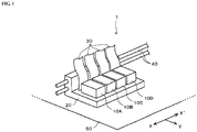
- FIG. 1 is a schematic block diagram showing an embodiment of an inkjet recording apparatus according to the present invention.
- the inkjet recording apparatus 1 includes a plurality of inkjet heads 10A to 10D.
- the four inkjet heads 10A to 10D for respective ink colors of, e.g., Y (yellow), M (magenta), C (cyan), and K (black) are juxtaposed in an X-X' direction (a main scanning direction) in the drawing, but the number of inkjet heads is not restricted in particular in the present invention, and at least one inkjet can suffice.
- the inkjet heads 10A to 10D are mounted on a common carriage 20 in such a manner that their nozzle surface sides face a recording medium 50, and electrically connected with a control apparatus (not shown in FIG. 1 ) provided in the inkjet recording apparatus 1 through flexible cables 30.
- the carriage 20 can reciprocate in the main scanning direction along guide rails 40 by a main scanning motor (not shown in FIG. 1 ). Further, the recording medium 50 is intermittently carried by each predetermined amount along a Y direction in the drawing crossing the main scanning direction by driving of a sub-scanning motor (not shown in FIG. 1 ).
- This inkjet recording apparatus 1 discharges inks from the respective inkjet heads 10A to 10D toward the recording medium 50 in a process of moving the respective inkjet heads 10A to 10D in the main scanning direction by movement of the carriage 20. Furthermore, printing (which will be also referred to as photographic printing hereinafter) of a predetermined image is performed on the recording medium 50 by cooperation of the movement of the inkjet heads 10A to 10D in the main scanning direction and the intermittent carriage of the recording medium 50 in a sub-scanning direction.
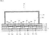
- inkjet heads 10A to 10D will now be described with reference to a cross-sectional view of the inkjet head shown in FIG. 2 . Since the respective inkjet heads 10A to 10D have the same configuration, a configuration of one inkjet head denoted by reference sign 10 will be described with reference to FIG. 2 .
- the inkjet head 10 is constituted by laminating a head substrate 11, a wiring substrate 12, and an adhesive resin layer 13.
- An ink manifold 14 is joined to an upper surface of the wiring substrate 12.
- the inside of the ink manifold 14 is a common ink chamber 14a in which an ink is stored between the ink manifold 14 and the wiring substrate 12.
- a nozzle plate 11a formed of an Si (silicon) substrate, an intermediate plate 11b formed of a glass substrate, a pressure chamber plate 11c formed of an Si (silicon) substrate, and a vibration plate (diaphragm) 11d formed of an SiO 2 thin film are laminated from a lower layer side in FIG. 2 .
- a plurality of nozzles 11e are opened in a lower surface of the nozzle plate 11a.
- a plurality of pressure chambers 15 which store the ink respectively are formed in the pressure chamber plate 11c.
- An upper wall of each pressure chamber 15 is formed of the vibration plate 11d, and a lower wall of the same is constituted of the intermediate plate 11b.
- the respective pressure chambers 15 communicate with the nozzles 11e through the intermediate plate 11b, respectively.
- Actuators 16 are laminated on an upper surface of the vibration plate 11d in correspondence with the respective pressure chambers 15 on one-on-one level.
- Each actuator 16 has a configuration that a piezoelectric element such as a thin film PZT is sandwiched between an upper electrode and a lower electrode (both of which are not shown) as driving electrodes.
- the upper electrode is arranged on an upper surface of an actuator main body, and the lower electrode is arranged on the lower surface of the piezoelectric element.
- the lower electrode extends on an upper surface of the vibration plate 11d, and constitutes a common electrode common to all the actuators 16.
- the lower electrode is earthed.
- the wiring substrate 12 is a substrate which includes wiring lines configured to apply driving signals from driving circuits (not shown in FIG. 1 and FIG. 2 ) provided for the inkjet heads 10A to 10D respectively to the driving electrodes of the respective actuators 16.
- the adhesive resin layer 13 is formed of, e.g., a thermosetting photosensitive adhesive resin sheet, and integrally bonds the head substrate 11 and the wiring substrate 12 between both the substrates 11 and 12. A gap corresponding to a thickness of this adhesive resin layer 13 is provided between both the substrates 11 and 12. Regions of the adhesive resin layer 13 corresponding to the actuators 16 and their peripheries are removed by exposure and development. Each actuator 16 is arranged in a space where this adhesive resin layer 13 is removed.
- each through hole 13a communicates with an ink supply path 12a formed in the wiring substrate 12, and the other end (a lower end) of the same communicates with the inside of the pressure chamber 15.
- the ink supply path 12a is opened in the common ink chamber 14a.
- the ink is supplied from the common ink chamber 14a into the respective pressure chambers 15 through the ink supply paths 12a and the through holes 13a. Further, when the driving signal including expansion pulses and contraction pulses is applied to the driving electrode of each actuator 16 from the driving circuits as will be described later, each actuator 16 deforms to vibrate the vibration plate 11d, and a capacity of each corresponding pressure chamber 15 expands and contracts. Consequently, a pressure applied to the ink in each pressure chamber 15 is changed, and the ink is discharged from each nozzle 11e toward the recording medium 50.
- FIG. 3 is a block diagram showing an embodiment of an electrical configuration of the inkjet recording apparatus 1.
- reference sign 100 denotes a control apparatus
- reference sign 200 denotes a host computer
- reference signs 60A to 60D denote driving circuits corresponding to the inkjet heads 10A to 10D on one-on-one level.
- the control apparatus 100 includes an interface controller 101, an image memory 102, a transferrer 103, a CPU 104, a main scanning motor 105, a sub-scanning motor 106, an input operation unit 107, a driving signal generation circuit 108, and others.
- the interface controller 101 fetches image information which is to be graphically printed on the recording medium 50 from the host computer 200 connected thereto through a communication line.
- this image information preferably includes gradation information of the ink which is to be discharged from each nozzle 11e of the inkjet heads 10A to 10D as well.
- the image memory 102 temporarily stores image information which is acquired through the interface controller 101.
- the image information in the image memory 102 is sent to the driving circuits 60A to 60D.
- the transferrer 103 transfers partial image information, which is recorded by single discharge from a plurality of nozzles of the respective inkjet heads 10A to 10D, from the image memory 102 to the respective driving circuits 60A to 60D.
- the transferrer 103 includes a timing generation circuit 103a and a memory control circuit 103b.
- the timing generation circuit 103a obtains positional information of the carriage 20 by, e.g., a non-illustrated encoder sensor.
- the memory control circuit 103b obtains an address of the partial image formation required for each of the inkjet heads 10A to 10D from this positional information.
- the memory control circuit 103b uses the address of this partial image information to perform reading from the image memory 102 and transfer to the driving circuits 60A to 60D.
- the CPU 104 is a control unit which integrates the inkjet recording apparatus 1, and controls carriage of the recording medium 50, movement of the carriage 20, discharge of the ink from each of the inkjet heads 10A to 10D, and others.
- the main scanning motor 105 is a motor which moves the carriage 20 shown in FIG. 1 in the main scanning direction.
- the sub-scanning motor 106 is a motor which carries the recording medium 50 in the sub-scanning direction. Driving of these motors 105 and 106 is controlled by the CPU 104.
- the input operation unit 107 is a portion through which the CPU 104 accepts various kinds of input operations performed by an operator, and it is constituted of, e.g., a touch panel.
- input keys provided in this input operation unit 107 preferably include a recording medium selection key to select a type of the recording medium 50.
- types of the recording medium 50 there are plain paper, glossy paper, cloth, a plastic sheet, and the like.
- the driving signal generation circuit 108 generates signal waveforms of the driving signals to discharge the ink from each of the inkjet heads 10A to 10D.
- the signal waveforms are synchronized with a latch signal of the image information of the timing generation circuit 103a, generated in accordance with each latch signal, and output to the driving circuits 60A to 60D.
- the driving circuits 60A to 60D drive the respective actuators 16 of the corresponding inkjet heads 10A to 10D.
- the driving circuits 60A to 60D are mounted on the carriage 20 together with the inkjet heads 10A to 10D, and electrically connected with the control apparatus 100 through the flexible cables 30.
- the driving circuits 60A to 60D have voltage setting units 61A to 61D, respectively. Each of the voltage setting units 61A to 61D sets a predetermined voltage to the signal waveforms of the driving signal supplied from the driving signal generation circuit 108.
- the driving circuits 60A to 60D apply the driving signal subjected to the voltage setting by each of the voltage setting units 61A to 61D to the driving electrode of the actuator 16 of each of the corresponding inkjet heads 10A to 10D based on the image information supplied from the image memory 102.
- a voltage value set by each of the voltage setting units 61A to 61D can be independently controlled by the CPU 104 in accordance with each of the driving circuits 60A to 60D.
- the driving signal will now be described.
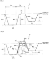
- FIG. 4 shows an embodiment of the driving signal output from each of the driving circuits 60A to 60D to each of the inkjet heads 10A to 10D.
- this driving signal P includes a first expansion pulse P1 which starts from a reference potential and expands the capacity of the pressure chamber 15, a first contraction pulse P2 which contracts the capacity of the pressure chamber 15 to discharge the ink from the nozzle, a second expansion pulse P3 which expands the capacity of the pressure chamber 15, and a second contraction pulse P4 which contracts the capacity of the pressure chamber 15 and returns to the reference potential in the mentioned order.
- a maintenance pulse P5 to maintain a potential of the first expansion pulse P1 is provided between an end edge of the first expansion pulse P1 and a start edge of the first contraction pulse P2. Additionally, an intermediate pulse P6 to hold a fixed potential is provided between an end edge of the first contraction pulse P2 and a start edge of the second expansion pulse P3. Further, a maintenance pulse P7 to maintain a potential of the second expansion pulse P3 is provided between an end edge of the second expansion pulse P3 and a start edge of the second contraction pulse P4.
- maintenance pulses P5 and P7 are flat pulses in this embodiment, but they may be slightly inclined upward so as not to obstruct the ink discharge without being restricted to the flat pulses.
- reference sign ⁇ V1 denotes a potential difference between the reference potential and the end edge of the first expansion pulse P1.
- Reference sign ⁇ V2 denotes a potential difference between the start edge and the end edge of the first contraction pulse P2.
- Reference sign ⁇ V3 designates a potential difference between the start edge of the second contraction pulse P4 and the reference potential.
- a driving signal P shown in this embodiment is constituted of a slope waveform in which rise and fall of each of the pulses P1, P2, P3, and P4 are inclined.
- the slope waveform is adopted, an effect of suppressing unstable discharge, e.g., a satellite, a speed abnormality, or bending can be provided, which is a preferred mode in the present invention.
- each pressure chamber 15 When this driving signal P is applied to the driving electrode of the actuator 16 of each of the inkjet heads 10A to 10D, the capacity of each pressure chamber 15 first starts to expand by the first expansion pulse P1 from an initial state where both expansion and contraction are yet to begin. Consequently, the ink flows into each pressure chamber 15 from the common ink chamber 14a. This expanded state is maintained for a period of the maintenance pulse P5.
- the capacity of the pressure chamber 15 which is in the expanded state starts to contract by the first contraction pulse P2.
- the contraction of the capacity of the pressure chamber 15 causes a positive pressure wave in the pressure chamber 15. Consequently, the ink is extruded from each nozzle 11e, and the ink is discharged. This contracted state is maintained for a period of the intermediate pulse P6.
- a pulse started by this second expansion pulse P3 is a cancel pulse which cancels a reverberation pressure wave in the pressure chamber 15 produced by the first contraction pulse P2.
- a negative pressure wave is produced in the pressure chamber 15. Consequently, the positive pressure wave produced in the pressure chamber 15 by the first contraction pulse P2 is canceled.
- the driving circuits 60A to 60D are configured to enable changing the potential difference ⁇ V2 in the driving signal P by using the respective voltage setting units 61A to 61D.
- FIG. 5 shows how the potential difference ⁇ V2 of the driving signal P is changed.
- FIG. 5 shows a state where the potential difference ⁇ V2 is increased or decreased while maintaining the potential difference ⁇ V1 of the driving signal P constant in order to increase or decrease a droplet amount.
- each of a potential at the start edge of the first contraction pulse P2 and a potential at the end edge of the second expansion pulse P3 is maintained at a fixed potential without changing, which is a preferred mode in the present invention.
- the driving circuits 60A to 60D change the potential difference ⁇ V2 of the driving signal P by using the voltage setting units 61A to 61D, thereby enabling changing between a driving signal Pa having the increased potential difference ⁇ V2 as indicated by an alternate long and short dash line in FIG. 5 and a driving signal Pc having the reduced potential difference ⁇ V2 as indicated by an alternate long and two short dashes line in FIG. 5 .
- the maintenance period of the intermediate pulse P6 is not changed, but inclinations of the first contraction pulse P2 and the second expansion pulse P3 are changed.
- the maintenance period of the intermediate pulse P6 may be changed so that the inclinations of the first contraction pulse P2 and the second expansion pulse P3 become constant.
- FIG. 6(a) is an explanatory drawing of a state where a large droplet is discharged by the driving signal whose potential difference ratio ⁇ V2/ ⁇ V1 has been greatly changed
- (b) is an explanatory drawing of a state where a medium droplet is discharged by the driving signal whose potential difference ratio ⁇ V2/ ⁇ V1 is not changed
- (c) is an explanatory drawing of a state where a small droplet is discharged by the driving signal whose potential difference ratio ⁇ V2/ ⁇ V1 has been slightly changed.
- the potential of the intermediate pulse P6 becomes relatively larger than that when the driving signal Pb, which is the reference potential, is applied, and hence a contraction amount of the capacity of each pressure chamber 15 provided by the first contraction pulse P2 also becomes large. Consequently, as shown in FIG. 6(a) , an extrusion amount L1 of an ink 300 extruded from each nozzle 11e becomes larger than an extrusion amount L2 of the ink 300 when the driving signal Pb is applied as shown in FIG. 6(b) . Moreover, the cancel pulse forcibly separates the ink 300 in a state where the extrusion amount is large. Thus, a droplet 301 whose droplet amount is larger than that of a droplet 302 shown in FIG. 6(b) discharged by the driving signal Pb is discharged from the nozzle 11e.
- the extrusion amounts of the ink 300 have a relationship of L1>L2>L3, and the droplet amounts of the discharged ink thereby have a relationship of the droplet 301>the droplet 302>the droplet 303.
- changing the potential difference ⁇ V2 of the driving signal P enables increasing or decreasing the droplet amount of the ink discharged from the nozzle 11e.
- a droplet speed of the ink does not substantially vary.
- the reason for this is as follows. Since the potential difference ⁇ V1 of the potential signal P is fixed, a degree of expansion of the capacity of each pressure chamber 15 provided by the first expansion pulse P1 is fixed irrespective of the droplet amount. Furthermore, the second expansion pulse P3 has a role to forcibly separate the ink discharged by the application of the first compression pulse P2 and cut the tail of the ink to be discharged. When the potential difference ⁇ V2 is large, discharge energy provided by the application of the first compression pulse P2 becomes large, and energy provided by the application of the second expansion pulse P3 also becomes large.
- the present inventor has confirmed that, when voltage adjustment was performed so that the potential difference ⁇ V2 could increase while maintaining the potential difference ⁇ V1 constant with respect to a standard droplet amount 3.0 pl of the ink discharged when the intermediate pulse P6 of the driving signal P was set to the reference potential, the droplet speed did not substantially change and a large droplet of 4.6 pl (an increase of approximately 50%) was successfully discharged at a maximum.
- the droplet speed did not substantially change, and a small droplet of 1.9 pl (a decrease of approximately 40%) was successfully discharged at a minimum. That is, it was possible to control a droplet amount from 1.9 pl to 4.6 pl which is approximately 2.5 times without changing the droplet speed.
- each of the driving circuits 60A to 60D it is preferable for each of the driving circuits 60A to 60D to enable changing the potential difference ⁇ V2 so that the potential difference ratio ⁇ V2/ ⁇ V1 of the driving signal P falls in the range of 0.8 to 1.2.
- the ink to be discharged begins to scatter when this ratio falls below 0.8, or the ink to be discharged begins to slur when the same exceeds 1.2, and the ink is hardly stabilized in both cases.
- the potential difference ⁇ V2 is changed so that the potential difference ratio ⁇ V2/ ⁇ V1 falls within the range of 0.8 to 1.2, different droplet amounts of the ink can be stably discharged in a state where the droplet speed does not vary.
- the potential difference ratio ⁇ V3/ ⁇ 2 of the potential differences ⁇ V2 and ⁇ V3 is 0.3 or more and 0.9 or less. In this range, the reverberation pressure wave produced in each pressure chamber 15 after applying the first contraction pulse P2 can be effectively suppressed, and the ink can be stably discharged. The suppression of the reverberation pressure wave is important for performing high-frequency driving. When this ratio is smaller than 0.3, it is not appropriate for the cancel pulse. It is preferable for the potential difference ratio ⁇ V3/ ⁇ V2 to be 0.5 or more and 0.9 or less, and 0.8 is most preferable.
- a period T1 from the start edge of the first expansion pulse P1 to the start edge of the first contraction pulse P2 of the driving signal P is 0.45 Tc or more and 0.55 Tc or less. Consequently, the ink can be most effectively discharged.
- Tc represents a vibration cycle of the ink in each pressure chamber 15.
- This Tc can be expressed by, e.g., the following formula.
- Tc 2 ⁇ Mn ⁇ Ms / Mn + Ms ⁇ Cc 1 / 2
- Mn is inertance in each nozzle 11e
- Ms is inertance in a supply port of the ink to each pressure chamber
- Cc is compliance of each pressure chamber 15.
- the inertance represents ease of movement of the ink in an ink flow path, and it is a mass of the ink per unit cross-sectional area.
- ⁇ density of the ink
- S is a cross-sectional area of a surface orthogonal to an ink flow direction of the ink flow path
- L is a length of the ink flow path.
- T2/T1 a period from the start edge of the first expansion pulse P1 to the start edge of the first contraction pulse P2 is T1 and a period from the start edge of the first contraction pulse P2 to the start edge of the second expansion pulse P3 is T2, it is essential for T2/T1 to be 0.6 or more and 1.2 or less.
- T2/T1 falls within this range, a satellite associated with the ink discharged from each nozzle 11e is suppressed, and the ink can be stably discharged.
- T2/T1 it is preferable for T2/T1 to be 0.6 or more and 1.0 or less since the discharge can be performed without reducing discharge efficiency, and further preferable for the same to be 0.7 or more and 0.9 or less since the discharge can be stably performed with the good discharge efficiency.
- the droplet amounts of the ink discharged from the same nozzle lie are determined based on gradation information included on image data to be graphically printed.
- the ink discharged from the same nozzle 11e per pixel is not restricted to one droplet, and it may be a plurality of droplets. That is, when the plurality of driving signals are continuously applied within one pixel cycle and the plurality of droplets of the ink are discharged from the same nozzle 11e, a large droplet having a larger droplet amount can be formed.
- the plurality of droplets of the ink are combined with each other during flight or overlap each other on the recording medium 50 to form a large dot.
- the driving signal P is used as a driving signal which forms at least a last droplet, a large dot having suppressed satellites can be formed.
- a diameter of a dot formed on the recording medium 50 by enabling changing a droplet amount of the ink discharged from the same nozzle 11e, i.e., enabling changing the potential difference ⁇ V2 of the driving signal P in accordance with a type of the recording medium 50.
- a diameter of a dot formed on the recording medium 50 differs depending on the adopted recording medium 50 with high ink absorbency like cloth or a counterpart with low ink absorbency like a plastic sheet.
- the ink absorbency becomes higher, the dot is apt to spread to the periphery while being absorbed by the recording medium 50, and a dot diameter tends to increase as compared with that when the ink absorbency is lower.
- a droplet amount of the ink discharged from the same nozzle 11e is changed depending on a type of the recording medium 50, and a diameter of a dot formed on the recording medium 50 is appropriately adjusted, thereby homogenizing an image.
- the potential difference ⁇ V2 of the driving signal P is reduced so that a droplet amount of the ink to be discharged can be decreased. Since a droplet speed does not vary, an impact positional displacement does not occur in accordance with each type of the recording medium 50, and discharge timing does not have to be again adjusted in accordance with each type of the recording medium 50.
- the type of the recording medium 50 is generally set by operating the input operation unit 107 for input by an operator. Furthermore, although not shown, the type of the recording medium 50 to be used may be automatically detected by, e.g., detecting a type of a dedicated tray prepared for each type of the recording medium 50 with the use of a sensor provided in the inkjet recording apparatus 1.
- the droplet amount of the ink can be changed in accordance with each type of the recording medium 50 as a matter of course. That is, as the ink absorbency of the recording medium 50 increases, the droplet amount of the ink to be discharged is changed to become small by reducing the potential difference ⁇ V2 of the driving signal P at the time of performing the multi-gradation printing. Consequently, an image formed in the multi-gradation printing can be homogenized irrespective of types of the recording medium 50.
- the inkjet recording apparatus and the inkjet recording method which enable changing the droplet amount without changing the droplet speed of the ink discharged from the same nozzle.
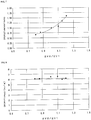
- a droplet volume and a droplet speed of the ink discharged from the same nozzle were measured by changing the potential difference ⁇ V2 of the driving signal P shown in FIG. 4 with the use of the inkjet head having the structure shown in FIG. 2 .
- the potential difference ratio ⁇ V2/ ⁇ V1 was changed while maintaining the potential difference ⁇ V1 constant.
- the droplet speed was calculated by recognizing an image of each droplet with the use of the droplet observation apparatus, and a distance that the droplet flies from a position which is 500 ⁇ m away from a nozzle surface during 50 ⁇ s was calculated by image processing.
- Table 1 and FIG. 8 show this result.
- [Table 1] ⁇ V2/ ⁇ V1 Droplet volume (pl) Droplet amount ratio Droplet speed (m/s) 0.8 1.90 0.64 6.1 0.85 2.33 0.78 6.15 1 2.98 1.00 6.52 1.1 3.22 1.08 6.65 1.15 4.03 1.35 5.8 1.2 4.75 1.59 6.27
- the droplet amount can be increased or decreased by changing the potential difference ⁇ V2 of the driving signal P.
- the droplet speed does not greatly vary due to a change in this potential difference ⁇ V2, and it is substantially constant.
Landscapes
- Particle Formation And Scattering Control In Inkjet Printers (AREA)
- Ink Jet (AREA)
Claims (20)
- Ein Tintenstrahlaufzeichnungsgerät, umfassend:einen Tintenstrahlkopf (10), der so konfiguriert ist, dass er eine Kapazität einer Druckkammer (15), die einem Aktuator (16) entspricht, ausdehnt und zusammenzieht, indem er ein Treibersignal an den Aktuator (16) anlegt, und dass er eine Tinte in der Druckkammer aus einer Düse (11e) ausstößt, um ein Drucken auf einem Aufzeichnungsmedium durchzuführen; undeine Treiberschaltung (60A - 60D), die so konfiguriert ist, dass sie das Treibersignal an den Aktuator (16) des Tintenstrahlkopfes (10) anlegt,wobei das Treibersignal einen ersten Expansionsimpuls, der von einem Referenzpotential ausgeht und die Kapazität der Druckkammer (15) erweitert, einen ersten Kontraktionsimpuls, der die Kapazität der Druckkammer (15) kontrahiert, um die Tinte aus der Düse (11e) auszustoßen, einen zweiten Expansionsimpuls, der die Kapazität der Druckkammer (15) erweitert, und einen Kontraktionsimpuls, der die Kapazität der Druckkammer (15) kontrahiert und zum Referenzpotential zurückkehrt, in der genannten Reihenfolge enthält, unddie Treiberschaltung (60A - 60D) so konfiguriert ist, dass sie unterschiedliche Tröpfchenmengen der Tinte aus derselben Düse (11e) ausstößt, indem sie eine Potentialdifferenz zwischen einer Startflanke und einer Endflanke des ersten Kontraktionsimpulses ändert;dadurch gekennzeichnet, dass
T2/T1 0,6 oder mehr und 1,2 oder weniger beträgt, wobei T1 eine Zeitspanne von der Startflanke des ersten Expansionsimpulses bis zur Startflanke des ersten Kontraktionsimpulses ist, und wobei T2 eine Zeitspanne von der Startflanke des ersten Kontraktionsimpulses bis zur Startflanke des zweiten Expansionsimpulses ist. - Das Tintenstrahlaufzeichnungsgerät nach Anspruch 1
wobei die Treiberschaltung (60A - 60D) so konfiguriert ist, dass sie die verschiedenen Tröpfchenmengen der Tinte aus derselben Düse durch Änderung der Potentialdifferenz ausstößt und somit einen Mehrstufendruck auf dem Aufzeichnungsmedium durchführt. - Das Tintenstrahlaufzeichnungsgerät nach Anspruch 1 oder 2,
wobei die Treiberschaltung (60A - 60D) so konfiguriert ist, dass sie eine Änderung der Potentialdifferenz in Übereinstimmung mit einem Typ des Aufzeichnungsmediums ermöglicht. - Das Tintenstrahlaufzeichnungsgerät nach Anspruch 1, 2 oder 3,
wobei die Treiberschaltung (60A - 60D) so konfiguriert ist, dass sie die Änderung einer Potentialdifferenz ΔV2 ermöglicht, so dass ein Potentialdifferenzverhältnis ΔV2/ΔV1 in einen Bereich von 0,8 bis 1,2 fällt, wobei ΔV1 eine Potentialdifferenz zwischen dem Referenzpotential und einer Endflanke des ersten Expansionsimpulses ist, und wobei ΔV2 eine Potentialdifferenz zwischen einer Startflanke und einer Endflanke des ersten Kontraktionsimpulses ist. - Das Tintenstrahlaufzeichnungsgerät nach einem der Ansprüche 1 bis 4,
wobei T1 0,45 Tc oder mehr und 0,55 Tc oder weniger beträgt, wobei Tc ein Schwingungszyklus der Tinte in der Druckkammer ist. - Das Tintenstrahlaufzeichnungsgerät nach einem der Ansprüche 1 bis 5,
wobei ΔV2 > ΔV3 erreicht wird, wobei ΔV2 die Potentialdifferenz zwischen der Startflanke und der Endflanke des ersten Kontraktionsimpulses ist und ΔV3 eine Potentialdifferenz zwischen der Startflanke des zweiten Kontraktionsimpulses und dem Referenzpotential ist. - Das Tintenstrahlaufzeichnungsgerät nach Anspruch 6,
wobei ein Potentialdifferenzverhältnis ΔV3/ΔV2 0,3 oder mehr und 0,9 oder weniger beträgt. - Das Tintenstrahlaufzeichnungsgerät nach Anspruch 6,
wobei ein Potentialdifferenzverhältnis ΔV3/ΔV2 0,5 oder mehr und 0,9 oder weniger beträgt. - Das Tintenstrahlaufzeichnungsgerät nach einem der Ansprüche 1 bis 8,
wobei T2/T1 1,0 oder weniger beträgt. - Das Tintenstrahlaufzeichnungsgerät nach einem der Ansprüche 1 bis 9,
wobei das Steuersignal eine Steigungswellenform aufweist. - Ein Tintenstrahlaufzeichnungsverfahren, umfassend das Expandieren und Kontrahieren einer Kapazität einer Druckkammer (15), die einem Aktuator (16) entspricht, durch Anlegen eines Treibersignals an den Aktuator (16) eines Tintenstrahlkopfes (10), und somit das Ausstoßen einer Tinte in der Druckkammer (15) aus einer Düse (11e), um das Drucken auf einem Aufzeichnungsmedium durchzuführen,
wobei das Treibersignal einen ersten Expansionsimpuls, der von einem Referenzpotential ausgeht und die Kapazität der Druckkammer (15) erweitert, einen ersten Kontraktionsimpuls, der die Kapazität der Druckkammer (15) kontrahiert, um die Tinte aus der Düse auszustoßen, einen zweiten Expansionsimpuls, der die Kapazität der Druckkammer (15) erweitert, und einen Kontraktionsimpuls, der die Kapazität der Druckkammer (15) kontrahiert und zum Referenzpotential zurückkehrt, in der genannten Reihenfolge enthält, und
wobei unterschiedliche Tröpfchenmengen der Tinte aus derselben Düse (11e) durch Änderung einer Potentialdifferenz zwischen einer Startflanke und einer Endflanke des ersten Kontraktionsimpulses ausgestoßen werden;
dadurch gekennzeichnet, dass
T2/T1 0,6 oder mehr und 1,2 oder weniger beträgt, wobei T1 eine Zeitspanne von der Startflanke des ersten Expansionsimpulses bis zur Startflanke des ersten Kontraktionsimpulses ist, und wobei T2 eine Zeitspanne von der Startflanke des ersten Kontraktionsimpulses bis zur Startflanke des zweiten Expansionsimpulses ist. - Das Tintenstrahlaufzeichnungsverfahren nach Anspruch 11,
wobei die verschiedenen Tröpfchenmengen der Tinte aus derselben Düse (11e) durch Änderung der Potentialdifferenz ausgestoßen werden und somit ein Mehrstufen-Druck auf dem Aufzeichnungsmedium durchgeführt wird. - Das Tintenstrahlaufzeichnungsverfahren nach Anspruch 11 oder 12,
wobei die Potentialdifferenz in Übereinstimmung mit einem Typ des Aufzeichnungsmediums geändert wird. - Das Tintenstrahlaufzeichnungsverfahren nach Anspruch 11, 12 oder 13,
wobei eine Potentialdifferenz ΔV2 so geändert wird, dass ein Potentialdifferenzverhältnis ΔV2/ΔV1 in einen Bereich von 0,8 bis 1,2 fällt, wobei ΔV1 eine Potentialdifferenz zwischen dem Referenzpotential und einer Endflanke des ersten Expansionsimpulses und ΔV2 eine Potentialdifferenz zwischen einer Startflanke und einer Endflanke des ersten Kontraktionsimpulses ist. - Das Tintenstrahlaufzeichnungsverfahren nach einem der Ansprüche 11 bis 14,
wobei T1 0,45 Tc oder mehr und 0,55 Tc oder weniger beträgt, wobei Tc ein Schwingungszyklus der Tinte in der Druckkammer ist. - Das Tintenstrahlaufzeichnungsverfahren nach einem der Ansprüche 11 bis 15,
wobei ΔV2 > ΔV3Δ erreicht wird, wobei ΔV2 die Potentialdifferenz zwischen der Startflanke des ersten Kontraktionsimpulses und der Endflanke des ersten Kontraktionsimpulses ist und ΔV3 eine Potentialdifferenz zwischen der Anfangsflanke des zweiten Kontraktionsimpulses und dem Referenzpotential ist. - Das Tintenstrahlaufzeichnungsverfahren nach Anspruch 16,
wobei ein Potentialdifferenzverhältnis ΔV3/ΔV2 0,3 oder mehr und 0,9 oder weniger beträgt. - Das Tintenstrahlaufzeichnungsverfahren nach Anspruch 16,
wobei ein Potentialdifferenzverhältnis ΔV3/ΔV2 0,5 oder mehr und 0,9 oder weniger beträgt. - Das Tintenstrahlaufzeichnungsverfahren nach einem der Ansprüche 11 bis 18,
wobei T2/T1 1,0 oder weniger beträgt. - Das Tintenstrahlaufzeichnungsverfahren nach einem der Ansprüche 11 bis 19,
wobei das Steuersignal eine Steigungswellenform aufweist.
Applications Claiming Priority (2)
| Application Number | Priority Date | Filing Date | Title |
|---|---|---|---|
| JP2015138856 | 2015-07-10 | ||
| PCT/JP2016/069910 WO2017010353A1 (ja) | 2015-07-10 | 2016-07-05 | インクジェット記録装置及びインクジェット記録方法 |
Publications (3)
| Publication Number | Publication Date |
|---|---|
| EP3321087A1 EP3321087A1 (de) | 2018-05-16 |
| EP3321087A4 EP3321087A4 (de) | 2018-07-25 |
| EP3321087B1 true EP3321087B1 (de) | 2021-01-06 |
Family
ID=57756959
Family Applications (1)
| Application Number | Title | Priority Date | Filing Date |
|---|---|---|---|
| EP16824333.5A Active EP3321087B1 (de) | 2015-07-10 | 2016-07-05 | Tintenstrahlaufnahmevorrichtung und tintenstrahlaufnahmeverfahren |
Country Status (4)
| Country | Link |
|---|---|
| US (1) | US10525706B2 (de) |
| EP (1) | EP3321087B1 (de) |
| JP (1) | JP6769436B2 (de) |
| WO (1) | WO2017010353A1 (de) |
Families Citing this family (5)
| Publication number | Priority date | Publication date | Assignee | Title |
|---|---|---|---|---|
| DK3398277T3 (en) | 2016-11-11 | 2020-10-26 | Ericsson Telefon Ab L M | Random access-procedure |
| EP3335881B1 (de) * | 2016-12-16 | 2021-02-17 | SII Printek Inc | Flüssigkeitsstrahlkopf, flüssigkeitsstrahlaufzeichnungsvorrichtung, verfahren zur ansteuerung eines flüssigkeitsstrahlkopfs und programm zur ansteuerung des flüssigkeitsstrahlkopfes |
| JP7559515B2 (ja) * | 2020-11-11 | 2024-10-02 | 株式会社リコー | 液体吐出装置、画像形成装置及び駆動波形生成方法 |
| JP7703373B2 (ja) * | 2021-06-17 | 2025-07-07 | 理想テクノロジーズ株式会社 | インクジェットヘッド |
| WO2025205868A1 (ja) * | 2024-03-27 | 2025-10-02 | 京セラ株式会社 | 液体吐出ヘッド、液体吐出記録装置、液体吐出ヘッドの制御方法、液体吐出記録装置の制御方法 |
Citations (1)
| Publication number | Priority date | Publication date | Assignee | Title |
|---|---|---|---|---|
| US8955932B2 (en) * | 2013-03-23 | 2015-02-17 | Ricoh Company, Ltd. | Image forming apparatus and head drive control method |
Family Cites Families (13)
| Publication number | Priority date | Publication date | Assignee | Title |
|---|---|---|---|---|
| JPH09164702A (ja) * | 1995-12-18 | 1997-06-24 | Brother Ind Ltd | インクジェット出力機 |
| JP3425113B2 (ja) * | 2000-03-03 | 2003-07-07 | 松下電器産業株式会社 | インクジェットヘッド及びインクジェット式記録装置 |
| JP2004042576A (ja) | 2002-07-16 | 2004-02-12 | Ricoh Co Ltd | ヘッド駆動制御装置及び画像記録装置 |
| JP2005212365A (ja) | 2004-01-30 | 2005-08-11 | Konica Minolta Holdings Inc | インクジェット記録装置 |
| JP2007144931A (ja) * | 2005-11-30 | 2007-06-14 | Konica Minolta Holdings Inc | インクジェット記録方法及びインクジェットプリンタ |
| EP2072259A1 (de) * | 2007-12-21 | 2009-06-24 | Agfa Graphics N.V. | System und Verfahren für zuverlässiges Hochgeschwindigkeits-Tintenstrahldrucken |
| JP2010179585A (ja) * | 2009-02-06 | 2010-08-19 | Seiko Epson Corp | 液体吐出装置、及び、液体吐出装置の制御方法 |
| WO2012121019A1 (ja) | 2011-03-08 | 2012-09-13 | コニカミノルタIj株式会社 | 液滴吐出装置及び液滴吐出ヘッドの駆動方法 |
| JP2015003396A (ja) * | 2013-06-19 | 2015-01-08 | セイコーエプソン株式会社 | インクジェット記録装置 |
| JP2015006777A (ja) * | 2013-06-26 | 2015-01-15 | セイコーエプソン株式会社 | 液体噴射装置、及び、液体噴射装置の制御方法 |
| JP2015058582A (ja) * | 2013-09-17 | 2015-03-30 | 富士フイルム株式会社 | 液滴吐出装置 |
| JP6005616B2 (ja) | 2013-09-30 | 2016-10-12 | 富士フイルム株式会社 | インクジェットヘッドの補正方法及びインクジェット記録装置 |
| JP6277706B2 (ja) * | 2013-12-20 | 2018-02-14 | セイコーエプソン株式会社 | 液体噴射装置、および、液体噴射装置の制御方法 |
-
2016
- 2016-07-05 EP EP16824333.5A patent/EP3321087B1/de active Active
- 2016-07-05 JP JP2017528612A patent/JP6769436B2/ja active Active
- 2016-07-05 US US15/743,106 patent/US10525706B2/en active Active
- 2016-07-05 WO PCT/JP2016/069910 patent/WO2017010353A1/ja not_active Ceased
Patent Citations (1)
| Publication number | Priority date | Publication date | Assignee | Title |
|---|---|---|---|---|
| US8955932B2 (en) * | 2013-03-23 | 2015-02-17 | Ricoh Company, Ltd. | Image forming apparatus and head drive control method |
Also Published As
| Publication number | Publication date |
|---|---|
| EP3321087A4 (de) | 2018-07-25 |
| EP3321087A1 (de) | 2018-05-16 |
| US10525706B2 (en) | 2020-01-07 |
| US20190077146A1 (en) | 2019-03-14 |
| JP6769436B2 (ja) | 2020-10-14 |
| JPWO2017010353A1 (ja) | 2018-04-19 |
| WO2017010353A1 (ja) | 2017-01-19 |
Similar Documents
| Publication | Publication Date | Title |
|---|---|---|
| US12064964B2 (en) | Inkjet head | |
| US11440315B2 (en) | Ink jet recording apparatus and ink jet recording method | |
| US9517621B2 (en) | Image forming apparatus including recording head for ejecting liquid droplets | |
| EP3321087B1 (de) | Tintenstrahlaufnahmevorrichtung und tintenstrahlaufnahmeverfahren | |
| US8864263B2 (en) | Inkjet recording device and method for generating drive waveform signal | |
| CN107405915B (zh) | 液体排出装置及其控制方法、设备驱动器以及打印系统 | |
| US10549529B2 (en) | Driving device and inkjet recording apparatus | |
| WO2000006387A1 (fr) | Tete d'enregistrement a jet d'encre et enregistreur a jet d'encre | |
| JP4257547B2 (ja) | 液体噴射ヘッドの製造方法及び駆動方法 | |
| US10906297B2 (en) | Liquid ejection device and image forming device | |
| US9931849B2 (en) | Liquid ejection apparatus, inkjet system, and flushing method | |
| US12059895B2 (en) | Liquid discharging head | |
| EP4011627B1 (de) | Tintenstrahlkopf | |
| JP6540302B2 (ja) | インクジェット記録装置及びインクジェット記録方法 | |
| JP7192547B2 (ja) | 液滴吐出装置及び液滴吐出方法 | |
| JP2020023058A (ja) | 液体吐出装置およびそれを備えたインクジェットプリンタ | |
| US20220234353A1 (en) | Inkjet head and inkjet recording device | |
| JPH10250068A (ja) | インクジェット記録装置 | |
| JP2017109480A (ja) | 画像形成装置、画像形成方法、及びプログラム | |
| JP6680129B2 (ja) | インクジェット記録装置及びインクジェット記録方法 | |
| JP2024031599A (ja) | 液体吐出ヘッド | |
| JPH10278269A (ja) | インクジェット記録装置 | |
| JP2000203016A (ja) | インクジェットヘッドの駆動装置 | |
| JP2002210956A (ja) | インクジェットヘッド及びインクジェット記録装置 |
Legal Events
| Date | Code | Title | Description |
|---|---|---|---|
| STAA | Information on the status of an ep patent application or granted ep patent |
Free format text: STATUS: THE INTERNATIONAL PUBLICATION HAS BEEN MADE |
|
| PUAI | Public reference made under article 153(3) epc to a published international application that has entered the european phase |
Free format text: ORIGINAL CODE: 0009012 |
|
| STAA | Information on the status of an ep patent application or granted ep patent |
Free format text: STATUS: REQUEST FOR EXAMINATION WAS MADE |
|
| 17P | Request for examination filed |
Effective date: 20171213 |
|
| AK | Designated contracting states |
Kind code of ref document: A1 Designated state(s): AL AT BE BG CH CY CZ DE DK EE ES FI FR GB GR HR HU IE IS IT LI LT LU LV MC MK MT NL NO PL PT RO RS SE SI SK SM TR |
|
| AX | Request for extension of the european patent |
Extension state: BA ME |
|
| REG | Reference to a national code |
Ref country code: DE Ref legal event code: R079 Ref document number: 602016051145 Country of ref document: DE Free format text: PREVIOUS MAIN CLASS: B41J0002015000 Ipc: B41J0002045000 |
|
| A4 | Supplementary search report drawn up and despatched |
Effective date: 20180627 |
|
| RIC1 | Information provided on ipc code assigned before grant |
Ipc: B41J 2/045 20060101AFI20180621BHEP |
|
| DAV | Request for validation of the european patent (deleted) | ||
| DAX | Request for extension of the european patent (deleted) | ||
| STAA | Information on the status of an ep patent application or granted ep patent |
Free format text: STATUS: EXAMINATION IS IN PROGRESS |
|
| 17Q | First examination report despatched |
Effective date: 20191216 |
|
| GRAP | Despatch of communication of intention to grant a patent |
Free format text: ORIGINAL CODE: EPIDOSNIGR1 |
|
| STAA | Information on the status of an ep patent application or granted ep patent |
Free format text: STATUS: GRANT OF PATENT IS INTENDED |
|
| INTG | Intention to grant announced |
Effective date: 20200716 |
|
| GRAS | Grant fee paid |
Free format text: ORIGINAL CODE: EPIDOSNIGR3 |
|
| GRAA | (expected) grant |
Free format text: ORIGINAL CODE: 0009210 |
|
| STAA | Information on the status of an ep patent application or granted ep patent |
Free format text: STATUS: THE PATENT HAS BEEN GRANTED |
|
| AK | Designated contracting states |
Kind code of ref document: B1 Designated state(s): AL AT BE BG CH CY CZ DE DK EE ES FI FR GB GR HR HU IE IS IT LI LT LU LV MC MK MT NL NO PL PT RO RS SE SI SK SM TR |
|
| REG | Reference to a national code |
Ref country code: GB Ref legal event code: FG4D |
|
| REG | Reference to a national code |
Ref country code: AT Ref legal event code: REF Ref document number: 1351936 Country of ref document: AT Kind code of ref document: T Effective date: 20210115 Ref country code: CH Ref legal event code: EP |
|
| REG | Reference to a national code |
Ref country code: DE Ref legal event code: R096 Ref document number: 602016051145 Country of ref document: DE |
|
| REG | Reference to a national code |
Ref country code: IE Ref legal event code: FG4D |
|
| REG | Reference to a national code |
Ref country code: NL Ref legal event code: MP Effective date: 20210106 |
|
| REG | Reference to a national code |
Ref country code: AT Ref legal event code: MK05 Ref document number: 1351936 Country of ref document: AT Kind code of ref document: T Effective date: 20210106 |
|
| REG | Reference to a national code |
Ref country code: LT Ref legal event code: MG9D |
|
| PG25 | Lapsed in a contracting state [announced via postgrant information from national office to epo] |
Ref country code: NO Free format text: LAPSE BECAUSE OF FAILURE TO SUBMIT A TRANSLATION OF THE DESCRIPTION OR TO PAY THE FEE WITHIN THE PRESCRIBED TIME-LIMIT Effective date: 20210406 Ref country code: PT Free format text: LAPSE BECAUSE OF FAILURE TO SUBMIT A TRANSLATION OF THE DESCRIPTION OR TO PAY THE FEE WITHIN THE PRESCRIBED TIME-LIMIT Effective date: 20210506 Ref country code: GR Free format text: LAPSE BECAUSE OF FAILURE TO SUBMIT A TRANSLATION OF THE DESCRIPTION OR TO PAY THE FEE WITHIN THE PRESCRIBED TIME-LIMIT Effective date: 20210407 Ref country code: FI Free format text: LAPSE BECAUSE OF FAILURE TO SUBMIT A TRANSLATION OF THE DESCRIPTION OR TO PAY THE FEE WITHIN THE PRESCRIBED TIME-LIMIT Effective date: 20210106 Ref country code: HR Free format text: LAPSE BECAUSE OF FAILURE TO SUBMIT A TRANSLATION OF THE DESCRIPTION OR TO PAY THE FEE WITHIN THE PRESCRIBED TIME-LIMIT Effective date: 20210106 Ref country code: LT Free format text: LAPSE BECAUSE OF FAILURE TO SUBMIT A TRANSLATION OF THE DESCRIPTION OR TO PAY THE FEE WITHIN THE PRESCRIBED TIME-LIMIT Effective date: 20210106 Ref country code: BG Free format text: LAPSE BECAUSE OF FAILURE TO SUBMIT A TRANSLATION OF THE DESCRIPTION OR TO PAY THE FEE WITHIN THE PRESCRIBED TIME-LIMIT Effective date: 20210406 |
|
| PG25 | Lapsed in a contracting state [announced via postgrant information from national office to epo] |
Ref country code: SE Free format text: LAPSE BECAUSE OF FAILURE TO SUBMIT A TRANSLATION OF THE DESCRIPTION OR TO PAY THE FEE WITHIN THE PRESCRIBED TIME-LIMIT Effective date: 20210106 Ref country code: AT Free format text: LAPSE BECAUSE OF FAILURE TO SUBMIT A TRANSLATION OF THE DESCRIPTION OR TO PAY THE FEE WITHIN THE PRESCRIBED TIME-LIMIT Effective date: 20210106 Ref country code: PL Free format text: LAPSE BECAUSE OF FAILURE TO SUBMIT A TRANSLATION OF THE DESCRIPTION OR TO PAY THE FEE WITHIN THE PRESCRIBED TIME-LIMIT Effective date: 20210106 Ref country code: LV Free format text: LAPSE BECAUSE OF FAILURE TO SUBMIT A TRANSLATION OF THE DESCRIPTION OR TO PAY THE FEE WITHIN THE PRESCRIBED TIME-LIMIT Effective date: 20210106 Ref country code: RS Free format text: LAPSE BECAUSE OF FAILURE TO SUBMIT A TRANSLATION OF THE DESCRIPTION OR TO PAY THE FEE WITHIN THE PRESCRIBED TIME-LIMIT Effective date: 20210106 |
|
| PG25 | Lapsed in a contracting state [announced via postgrant information from national office to epo] |
Ref country code: IS Free format text: LAPSE BECAUSE OF FAILURE TO SUBMIT A TRANSLATION OF THE DESCRIPTION OR TO PAY THE FEE WITHIN THE PRESCRIBED TIME-LIMIT Effective date: 20210506 |
|
| REG | Reference to a national code |
Ref country code: DE Ref legal event code: R097 Ref document number: 602016051145 Country of ref document: DE |
|
| PG25 | Lapsed in a contracting state [announced via postgrant information from national office to epo] |
Ref country code: CZ Free format text: LAPSE BECAUSE OF FAILURE TO SUBMIT A TRANSLATION OF THE DESCRIPTION OR TO PAY THE FEE WITHIN THE PRESCRIBED TIME-LIMIT Effective date: 20210106 Ref country code: EE Free format text: LAPSE BECAUSE OF FAILURE TO SUBMIT A TRANSLATION OF THE DESCRIPTION OR TO PAY THE FEE WITHIN THE PRESCRIBED TIME-LIMIT Effective date: 20210106 Ref country code: SM Free format text: LAPSE BECAUSE OF FAILURE TO SUBMIT A TRANSLATION OF THE DESCRIPTION OR TO PAY THE FEE WITHIN THE PRESCRIBED TIME-LIMIT Effective date: 20210106 |
|
| PLBE | No opposition filed within time limit |
Free format text: ORIGINAL CODE: 0009261 |
|
| STAA | Information on the status of an ep patent application or granted ep patent |
Free format text: STATUS: NO OPPOSITION FILED WITHIN TIME LIMIT |
|
| PG25 | Lapsed in a contracting state [announced via postgrant information from national office to epo] |
Ref country code: DK Free format text: LAPSE BECAUSE OF FAILURE TO SUBMIT A TRANSLATION OF THE DESCRIPTION OR TO PAY THE FEE WITHIN THE PRESCRIBED TIME-LIMIT Effective date: 20210106 Ref country code: RO Free format text: LAPSE BECAUSE OF FAILURE TO SUBMIT A TRANSLATION OF THE DESCRIPTION OR TO PAY THE FEE WITHIN THE PRESCRIBED TIME-LIMIT Effective date: 20210106 Ref country code: SK Free format text: LAPSE BECAUSE OF FAILURE TO SUBMIT A TRANSLATION OF THE DESCRIPTION OR TO PAY THE FEE WITHIN THE PRESCRIBED TIME-LIMIT Effective date: 20210106 |
|
| 26N | No opposition filed |
Effective date: 20211007 |
|
| PG25 | Lapsed in a contracting state [announced via postgrant information from national office to epo] |
Ref country code: ES Free format text: LAPSE BECAUSE OF FAILURE TO SUBMIT A TRANSLATION OF THE DESCRIPTION OR TO PAY THE FEE WITHIN THE PRESCRIBED TIME-LIMIT Effective date: 20210106 Ref country code: AL Free format text: LAPSE BECAUSE OF FAILURE TO SUBMIT A TRANSLATION OF THE DESCRIPTION OR TO PAY THE FEE WITHIN THE PRESCRIBED TIME-LIMIT Effective date: 20210106 |
|
| PG25 | Lapsed in a contracting state [announced via postgrant information from national office to epo] |
Ref country code: SI Free format text: LAPSE BECAUSE OF FAILURE TO SUBMIT A TRANSLATION OF THE DESCRIPTION OR TO PAY THE FEE WITHIN THE PRESCRIBED TIME-LIMIT Effective date: 20210106 |
|
| REG | Reference to a national code |
Ref country code: CH Ref legal event code: PL |
|
| PG25 | Lapsed in a contracting state [announced via postgrant information from national office to epo] |
Ref country code: MC Free format text: LAPSE BECAUSE OF FAILURE TO SUBMIT A TRANSLATION OF THE DESCRIPTION OR TO PAY THE FEE WITHIN THE PRESCRIBED TIME-LIMIT Effective date: 20210106 |
|
| REG | Reference to a national code |
Ref country code: BE Ref legal event code: MM Effective date: 20210731 |
|
| PG25 | Lapsed in a contracting state [announced via postgrant information from national office to epo] |
Ref country code: LI Free format text: LAPSE BECAUSE OF NON-PAYMENT OF DUE FEES Effective date: 20210731 Ref country code: IT Free format text: LAPSE BECAUSE OF FAILURE TO SUBMIT A TRANSLATION OF THE DESCRIPTION OR TO PAY THE FEE WITHIN THE PRESCRIBED TIME-LIMIT Effective date: 20210106 Ref country code: CH Free format text: LAPSE BECAUSE OF NON-PAYMENT OF DUE FEES Effective date: 20210731 |
|
| PG25 | Lapsed in a contracting state [announced via postgrant information from national office to epo] |
Ref country code: IS Free format text: LAPSE BECAUSE OF FAILURE TO SUBMIT A TRANSLATION OF THE DESCRIPTION OR TO PAY THE FEE WITHIN THE PRESCRIBED TIME-LIMIT Effective date: 20210506 Ref country code: LU Free format text: LAPSE BECAUSE OF NON-PAYMENT OF DUE FEES Effective date: 20210705 |
|
| PG25 | Lapsed in a contracting state [announced via postgrant information from national office to epo] |
Ref country code: IE Free format text: LAPSE BECAUSE OF NON-PAYMENT OF DUE FEES Effective date: 20210705 Ref country code: BE Free format text: LAPSE BECAUSE OF NON-PAYMENT OF DUE FEES Effective date: 20210731 |
|
| PG25 | Lapsed in a contracting state [announced via postgrant information from national office to epo] |
Ref country code: HU Free format text: LAPSE BECAUSE OF FAILURE TO SUBMIT A TRANSLATION OF THE DESCRIPTION OR TO PAY THE FEE WITHIN THE PRESCRIBED TIME-LIMIT; INVALID AB INITIO Effective date: 20160705 |
|
| P01 | Opt-out of the competence of the unified patent court (upc) registered |
Effective date: 20230510 |
|
| PG25 | Lapsed in a contracting state [announced via postgrant information from national office to epo] |
Ref country code: NL Free format text: LAPSE BECAUSE OF NON-PAYMENT OF DUE FEES Effective date: 20210206 Ref country code: CY Free format text: LAPSE BECAUSE OF FAILURE TO SUBMIT A TRANSLATION OF THE DESCRIPTION OR TO PAY THE FEE WITHIN THE PRESCRIBED TIME-LIMIT Effective date: 20210106 |
|
| PG25 | Lapsed in a contracting state [announced via postgrant information from national office to epo] |
Ref country code: MK Free format text: LAPSE BECAUSE OF FAILURE TO SUBMIT A TRANSLATION OF THE DESCRIPTION OR TO PAY THE FEE WITHIN THE PRESCRIBED TIME-LIMIT Effective date: 20210106 |
|
| PG25 | Lapsed in a contracting state [announced via postgrant information from national office to epo] |
Ref country code: TR Free format text: LAPSE BECAUSE OF FAILURE TO SUBMIT A TRANSLATION OF THE DESCRIPTION OR TO PAY THE FEE WITHIN THE PRESCRIBED TIME-LIMIT Effective date: 20210106 |
|
| PG25 | Lapsed in a contracting state [announced via postgrant information from national office to epo] |
Ref country code: MT Free format text: LAPSE BECAUSE OF FAILURE TO SUBMIT A TRANSLATION OF THE DESCRIPTION OR TO PAY THE FEE WITHIN THE PRESCRIBED TIME-LIMIT Effective date: 20210106 |
|
| PGFP | Annual fee paid to national office [announced via postgrant information from national office to epo] |
Ref country code: GB Payment date: 20250529 Year of fee payment: 10 |
|
| PGFP | Annual fee paid to national office [announced via postgrant information from national office to epo] |
Ref country code: FR Payment date: 20250610 Year of fee payment: 10 |
|
| PGFP | Annual fee paid to national office [announced via postgrant information from national office to epo] |
Ref country code: DE Payment date: 20250604 Year of fee payment: 10 |