EP3318331B1 - Installation de broyage dotée d'une machine à broyer - Google Patents
Installation de broyage dotée d'une machine à broyer Download PDFInfo
- Publication number
- EP3318331B1 EP3318331B1 EP17199538.4A EP17199538A EP3318331B1 EP 3318331 B1 EP3318331 B1 EP 3318331B1 EP 17199538 A EP17199538 A EP 17199538A EP 3318331 B1 EP3318331 B1 EP 3318331B1
- Authority
- EP
- European Patent Office
- Prior art keywords
- comminuting
- machine
- displacement apparatus
- displacement
- housing wall
- Prior art date
- Legal status (The legal status is an assumption and is not a legal conclusion. Google has not performed a legal analysis and makes no representation as to the accuracy of the status listed.)
- Active
Links
- 238000006073 displacement reaction Methods 0.000 claims description 30
- 239000013590 bulk material Substances 0.000 claims 1
- 230000003014 reinforcing effect Effects 0.000 claims 1
- 238000000034 method Methods 0.000 description 10
- 229910052500 inorganic mineral Inorganic materials 0.000 description 6
- 239000011707 mineral Substances 0.000 description 6
- 238000010276 construction Methods 0.000 description 5
- 229910000831 Steel Inorganic materials 0.000 description 3
- 238000009434 installation Methods 0.000 description 3
- 230000010354 integration Effects 0.000 description 3
- 238000012423 maintenance Methods 0.000 description 3
- 239000011435 rock Substances 0.000 description 3
- 238000005096 rolling process Methods 0.000 description 3
- 239000010959 steel Substances 0.000 description 3
- 239000011324 bead Substances 0.000 description 2
- 238000006243 chemical reaction Methods 0.000 description 2
- 239000007787 solid Substances 0.000 description 2
- 230000006978 adaptation Effects 0.000 description 1
- 238000007792 addition Methods 0.000 description 1
- 239000004568 cement Substances 0.000 description 1
- 230000000694 effects Effects 0.000 description 1
- 239000012467 final product Substances 0.000 description 1
- 230000005484 gravity Effects 0.000 description 1
- 238000003780 insertion Methods 0.000 description 1
- 230000037431 insertion Effects 0.000 description 1
- 239000000463 material Substances 0.000 description 1
- 238000005272 metallurgy Methods 0.000 description 1
- 238000003801 milling Methods 0.000 description 1
- 238000005065 mining Methods 0.000 description 1
- 230000000750 progressive effect Effects 0.000 description 1
- 238000010298 pulverizing process Methods 0.000 description 1
- 239000002994 raw material Substances 0.000 description 1
- 239000006228 supernatant Substances 0.000 description 1
Images


Classifications
-
- B—PERFORMING OPERATIONS; TRANSPORTING
- B02—CRUSHING, PULVERISING, OR DISINTEGRATING; PREPARATORY TREATMENT OF GRAIN FOR MILLING
- B02C—CRUSHING, PULVERISING, OR DISINTEGRATING IN GENERAL; MILLING GRAIN
- B02C4/00—Crushing or disintegrating by roller mills
- B02C4/28—Details
-
- B—PERFORMING OPERATIONS; TRANSPORTING
- B02—CRUSHING, PULVERISING, OR DISINTEGRATING; PREPARATORY TREATMENT OF GRAIN FOR MILLING
- B02C—CRUSHING, PULVERISING, OR DISINTEGRATING IN GENERAL; MILLING GRAIN
- B02C18/00—Disintegrating by knives or other cutting or tearing members which chop material into fragments
- B02C18/06—Disintegrating by knives or other cutting or tearing members which chop material into fragments with rotating knives
- B02C18/14—Disintegrating by knives or other cutting or tearing members which chop material into fragments with rotating knives within horizontal containers
- B02C18/142—Disintegrating by knives or other cutting or tearing members which chop material into fragments with rotating knives within horizontal containers with two or more inter-engaging rotatable cutter assemblies
-
- B—PERFORMING OPERATIONS; TRANSPORTING
- B02—CRUSHING, PULVERISING, OR DISINTEGRATING; PREPARATORY TREATMENT OF GRAIN FOR MILLING
- B02C—CRUSHING, PULVERISING, OR DISINTEGRATING IN GENERAL; MILLING GRAIN
- B02C23/00—Auxiliary methods or auxiliary devices or accessories specially adapted for crushing or disintegrating not provided for in preceding groups or not specially adapted to apparatus covered by a single preceding group
-
- B—PERFORMING OPERATIONS; TRANSPORTING
- B66—HOISTING; LIFTING; HAULING
- B66F—HOISTING, LIFTING, HAULING OR PUSHING, NOT OTHERWISE PROVIDED FOR, e.g. DEVICES WHICH APPLY A LIFTING OR PUSHING FORCE DIRECTLY TO THE SURFACE OF A LOAD
- B66F3/00—Devices, e.g. jacks, adapted for uninterrupted lifting of loads
- B66F3/24—Devices, e.g. jacks, adapted for uninterrupted lifting of loads fluid-pressure operated
- B66F3/25—Constructional features
- B66F3/36—Load-engaging elements
-
- B—PERFORMING OPERATIONS; TRANSPORTING
- B02—CRUSHING, PULVERISING, OR DISINTEGRATING; PREPARATORY TREATMENT OF GRAIN FOR MILLING
- B02C—CRUSHING, PULVERISING, OR DISINTEGRATING IN GENERAL; MILLING GRAIN
- B02C18/00—Disintegrating by knives or other cutting or tearing members which chop material into fragments
- B02C18/06—Disintegrating by knives or other cutting or tearing members which chop material into fragments with rotating knives
- B02C18/16—Details
- B02C2018/162—Shape or inner surface of shredder-housings
Definitions
- the present invention relates to a crushing plant with a crushing machine, in particular crusher with a crusher or sizer to reduce the grain size of a mineral, the crushing machine having a machine housing and at least one traversing device, wherein the machine housing at least partially a housing wall with at least partially over a width of Housing wall extending stiffening ribs or in the form of a slab, and wherein the traversing device attached to the housing wall and alternately in a travel position in which the crusher is stationary on a support member of the traversing device, and in a standing position in which the crushing machine is stationary, brought is.
- Crushing plants are used in mining and metallurgy to adjust grain sizes of a mineral to a desired grain size by means of the crusher.
- the mineral may be, for example, a rock, an ore, cement or other material.
- crushers are crushers, sizers and roller presses.
- a subtype of a crusher for making ballast-like bulk goods is a roll crusher.
- Crushing plants for fine comminution or pulverization are, for example, roller presses and mills. In crushing plants raw materials are crushed in bulk. These plants regularly have shredding capacities of many tons per hour. The systems are correspondingly large and stable.
- the crushing plant comprises in addition to the crushing machine as a central component other components, such as a supporting structure on which the crushing plant is and is movable.
- crushing tools such as crusher rolls
- the housing walls are not simple steel walls but with a supporting structure of stiffening ribs highly stable wall structures or solid walls, such as 350 mm thick steel slabs.
- the crushing plants are differentiated depending on their structure and their mobility, for example in a progressive open pit in stationary, semi-mobile and fully mobile crushing plants.
- CN 103586106 B and CN 104368412 B disclose by means of rollers movable crushing machines.
- the housing wall has at least one recess formed for installation of the traversing device, so that the traversing device is at least largely integrated into the housing wall within its width by being at least partially locatable in the recess ,
- the recess is contained in the housing wall of the crushing machine according to the invention by default.
- the traversing device can be mounted, but it can also be temporarily mounted, for example, for maintenance or integrated into the crusher.
- the recess can be made by milling a slab.
- a slab is a slab massive across its width.
- the recess may extend through the stiffening ribs and through cavities between the stiffening ribs.
- the integration of the travel device in the housing wall is by no means trivial but must be thoroughly planned and taken into account in the construction of the plant wall. By other arrangements and additions of construction elements or stiffening ribs within the housing wall can ultimately, despite the existing recess, the construction of an undiminished stable Housing wall can be achieved.
- the integration of the traversing device in the housing wall releases space that was occupied in a conventional traversing device.
- the traversing device can be arranged by its integrable construction near the center of gravity of the crushing machine.
- a direct force entry into the housing wall is possible, so that the advantages of the crushing plant according to the invention not only limited to their compactness but pass on, for example, an excellent mechanical reliability in the spatial environment of at least one traversing device.
- the crusher In its standing position, the crusher stands on a solid structure or ground. In the intended use of the crushing machine in the stand position, a mineral, such as a mined rock or ore is continuously fed into the crushing machine and comminuted in the machine housing by crushing tools to a desired size of the final product, for example, broken. In the stand position, the traversing device has no function. However, it can be maintained for its later use within the housing wall of the crushing plant.
- the displacement position of the crushing machine is a position in which it can be moved or moved from a first location to a second location.
- the crushing machine is no longer directly on its ground but on the intervening at least one traversing device and on the support element of the traversing device.
- the support element is mounted in a support element guide, so that the forces occurring during the movement process are introduced into the housing wall with the participation of the support element and the support element guide.
- the traveling device may comprise at least one wheel as a component of the support element. Overall, several wheels, rollers, rolling or sliding devices, for example, four wheels for moving the crushing machine may be present.
- the traversing device can be completely integrated in the housing wall, so that the housing wall has its usual width in the region of the traversing device.
- the width of the housing wall in the region of the travel device is slightly increased.
- the displacement device is partially or largely integrated in the housing wall within its width or original wall thickness.
- the system housing and the housing walls may have stiffening ribs at regular intervals.
- the integration of the traversing device in the housing wall can associated with the constructive feature that the traversing device extends through at least one stiffening rib, wherein the stiffening rib or the plurality of stiffening ribs corresponding openings or recesses for receiving the traversing device.
- the traversing device of the crushing plant according to the invention can have a lifting device, in particular a hydraulic cylinder, wherein the traversing device or its supporting element can be moved out into the traversing position and the crusher can be raised at least partially with the lifting device.
- a lifting device in particular a hydraulic cylinder
- the traversing device or its supporting element can be moved out into the traversing position and the crusher can be raised at least partially with the lifting device.
- Between the hydraulic cylinder and the support element may be arranged a joint, for example a calotte head.
- the required for the actuation of the hydraulic cylinder hydraulic pump can be temporarily provided as a manually or motor driven separate hydraulic module with which two or four hydraulic cylinders can be driven simultaneously, so that the crushing machine in one step or in several steps can be lifted.
- the traversing device may be a device of variable length, wherein the length of the traversing device may be greater in the traversing position than in the stationary position. In this case, the traversing device is largely extended in the displacement position. The maximum extension length of the traversing device can be greater than that required to set the traversing position.
- the lifting device may be part of the traversing device, for example a hydraulic cylinder or an electromechanical drive.
- the traversing device can also be a simpler mechanical device, for example if an external device, for example a crane, and for moving an external auxiliary device, for example a trolley, are used as the lifting device.
- the traversing device may have a pressure element and a Druckmaschinein Kunststoffö réelle, wherein the support element, the pressure element and the pressure element receiving are formed to support the traversing device during the process of the crushing machine relative to the housing wall and at least partially absorb the weight of the crushing machine.
- the supporting of the weight of the crushing machine is connected to an entry of the supporting force in the housing wall, where at the supporting point of the pressure resulting from the supporting force is to be included.
- a pressure element can be arranged as a mechanically sufficiently resilient component, so that there is no risk of damage to the pressure element during its use.
- the pressure element may be a pressure plate with large-area force surfaces, so that only elastic but no plastic deformation of the pressure plate occur. With several mounted on the housing wall traversing distributes the weight. The proportionate weight force to be absorbed by a single travel device is reduced with the number of available travel devices.
- the traversing device can have at least one wheel and at least one wheel receiver.
- the traversing device can have exactly one wheel; but it can also have several wheels, for example in a swing arrangement.
- the wheels may for example be equipped with a sliding bearing or with a roller bearing.
- the traversing device can also be designed without its own wheels, for example as a purely mechanical support for getting up on a traveling trolley or a rolling carriage. In this case, wheels, rollers or other means for reducing friction can be arranged in the travel trolley or the rolling carriage.
- the traversing device is designed for the method on a rail and it has at least one rail guide, wherein the rail guide is designed for the lateral overlapping of the rail.
- the rail guide may be formed, for example, as a one-sided flange of a wheel, as a double-track rim or as a supernatant of a wheel.
- the rail guide may be realized by a bead on the rail, this bead serving as a lateral guide for the wheel (s). With rails, a travel over the rail track can be predetermined and well controlled.
- the position of the traversing device can be specified and secured over the rail during the traversing process.
- the traversing device can be rotatable about a substantially vertical axis by in particular at least 90 °, wherein by the rotation of a travel direction of the traversing device can be fixed and wherein an angular position of the traversing device is preferably adjustable by a Verrieglungselement in a fixed travel direction.
- the traversing device can be used to move in several directions on the ground plane, for example, in a direction along the housing wall in which the traversing device is located, and in a direction transverse thereto, ie 90 ° turned to the housing wall. It can also be provided in adaptation to special local conditions other angles than 90 °.
- the crushing plant according to the invention may comprise a structure comprising rails, wherein the crushing machine can be moved on the supporting structure.
- the crushing machine can be arranged for example in such a height in the crushing plant that a conveyor belt or a wagon can be arranged under the crushing machine for receiving the minced mineral.
- the crushing system may comprise a rotatable about a pin turntable with a rail segment located thereon.
- the turntable can be understood as a kind of switch, with which the selection of one of several traversing directions is made possible, whereby the several traversing directions are defined by rails laid in different directions.
- the positioning and mounting of the turntable can be advantageously realized with the inclusion of a pin.
- a rail crossing can also be realized differently, for example by fixed, intersecting rails, which are interrupted in the vicinity of the crossing point, wherein the interruption areas are fillable by insertable rail segments.
- the rail segment may have a greater width in a central region of the turntable than the rails next to the turntable and preferably have a bulge for receiving a wheel.
- the greater width of the rail segment on the turntable improves the fault tolerance of the rail system. Even with small angle tolerances occurring in the angular position of the turntable and / or the traversing device occur when driving a wheel of the rail segment on the turntable on an adjacent rail no damage due to notch effects. Due to the bulge of the rail segment on the fulcrum accurate positioning of the wheel can be ensured on the fulcrum.
- the traversing device has a fork-like rail guide, with which the rail segment can be engaged on both sides, so that upon rotation of the traversing device, an engagement of the rail segment in the rail guide can remain.
- the turntable which is in engagement with the travel device, can be coupled in a coupled manner to rotatable components of the travel device.
- the fork-like rail guide with two lateral guide elements adjacent to both sides of the rail provides a universal guide with benefits in various movements.
- the invention also includes combinations of features that have not been explicitly described together. Successive features are to be understood as separate features, not as a compelling combination of features.
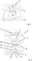
- FIG. 1 is a machine housing 2 of a roll crusher shown as an embodiment of a crushing machine of a crushing plant according to the invention.
- two traversing devices 1 can be arranged in the housing wall 3 .
- the rear travel device 1 is shown in the assembled state and the front travel device in an exploded view in an exploded state.
- two further traversing devices 1 are arranged, but these are hidden and therefore in Fig. 1 not visible.
- the Figures 2-6 show the housing wall 3 of Fig. 1
- the housing wall 3 is part of the machine housing 2 and has a structure of stiffening ribs 14.
- the stiffening ribs 14 are welded to the stiffening of other steel plates and thus involved in the provision of the required mechanical strength of the housing wall 3.
- the traversing device 1 has in the presented example a lifting device, which is mainly the hydraulic cylinder 4.
- the lifting device may be a support member 16 of the traversing device 1, which in FIGS. 5 and 6 can be seen, press down out of the housing wall 3 while lifting the crushing machine in the traversing device 1.
- the use of the hydraulic cylinder 4 is provided only at a standstill of the crushing machine at a location to push the support member 16 sufficiently far from the hydraulic cylinder 4, so that a Druckieriin Kunststoffö réelle 6 is opened for insertion or removal of a pressure element 5.
- the hydraulic cylinder 4 is preferably relieved and the load in the area of the traversing device 1 is over the Support member 16 and the pressure element 5 in the located above the pressure element 5 stiffening rib 14 or initially in a threaded ring 20, which serves to attach the hydraulic cylinder 4, initiated.
- the pressure element 5 directs the forces occurring as a pressure plate over a large area in the housing wall 3, so that no voltage peaks and damage in this area can occur during the movement of the crushing machine.
- Under the pressure element 5, the construction element of a cylinder jacket-shaped wall or stiffening rib 15 can be seen, which serves as a support element guide for the cylindrical support element 16 located behind it.
- the crushing machine on their traversing devices 1 in a substantially horizontal plane is movable.
- displacement position is the support member 16 and the comminution machine on a in FIGS. 5 and 6 visible wheel 17 and there is a mobility in the Y direction.
- rail guides 8 are arranged in Fig. 2 bifurcate over the rail 8 and thus prevent movement in the X direction and allow only the movement in the Y direction.
- the cylindrical support member 16 of the traversing apparatus shown is rotatable about the Z axis and at two angles namely at 0 °, for a method in the X direction and at 90 ° for movement in the Y direction with a locking element 9 can be locked.
- the Verrieglungselement 9 is a cuboid bar, which is secured in its inserted position on the also visible securing element against accidental sliding out.
- FIG. 4 is the Verrieglungselement 9 completely seen in the pulled-out position.
- the structure 10 has a hub 11 with a rail segment 12 formed thereon, which is rotatable about a central, vertically oriented pin about the Z-axis. With the two visible bolts, the turntable 11 is alternately lockable in the X-orientation or the Y-orientation. In the middle of the illustrated rail segment 12, a cylindrical bulge 13 is formed, in which the wheel 17 is provided during a simultaneous rotation of the rotary disk 11 and the support member 16.
- FIG. 3 shows the traversing device 1 in a slightly smaller section and that in a standing position, in which the pressure element 5 is kept fixed on its shelf and the Hydraulic cylinder 4 is retracted so that the crushing machine is directly or indirectly on the structure 10 and thus eg productive for breaking rocks can be used or can be maintained.
- a pressure element receiving opening 6 is visible because the pressure element 5 has been removed manually.
- the pressure element 5 is taken out here, stored and stored secured by screws at a storage location within the housing wall 3, as shown in FIG. 4 you can see.
- the inner raised cylindrical rim within the annular collar serves as a stop for the horseshoe-shaped pressure element 5 when it is inserted into the pressure element receiving opening 6.
- the pressure element 5 has a holding plate and a handle.
- FIGS. 3 and 4 are not shown between the supporting structure 10 and the housing wall 3 lining plates arranged so that the weight of the crushing machine acts on the lining sheets and not on the traversing device 1.
- FIG. 4 shows the traversing device 1 during a conversion from the in Fig. 2 and 6 illustrated Y-orientation of the cylindrical support member 16, in the X-orientation, the Fig. 5 is shown.
- the housing wall 3 is shown partially open to allow insight into internal parts of the traversing device 1.
- the cylindrical support member 16 is a perforated cylinder with a rectangular recess 18 for receiving the wheel 17. Because of the rectangular recess 18, the support member is formed in the illustrated embodiment at the same time as a fork, which serves as a guide of the wheel 17 and also to form the forked rail guide 8 serves. In other embodiments, not shown, the rail guide is realized differently, for example by a double lane on the wheel (17).
- the wheel 17 and the Verrieglungselement 9 have substantially the same width as the cuboid recess 18, so that the recess 18 as a guide for the wheel 17 during the process and as a guide for the Verrieglungselement 9 when lifting and lowering the lifting device is usable.
- a cylindrical and cuboid recess 19 of the support member 16 serves in its cylindrical part of the introduction of a wheel axle and in its cuboid part as a guide trench for the Verrieglungselement 9 at a height adjustment of the support member 16 and simultaneously locked angular position.
- the Verrieglungselement 9 is located in the representations of Fig. 4 and Fig.
- the traveling device 1 shown can be used universally and efficiently for movements in both the X direction and in the Y direction.
- multi-stage traversing in a sequence of different directions are quickly and safely feasible.
- the presented traversing device thus makes a contribution to a high availability of the crushing plant according to the invention.
Landscapes
- Engineering & Computer Science (AREA)
- Food Science & Technology (AREA)
- Life Sciences & Earth Sciences (AREA)
- Geology (AREA)
- Mechanical Engineering (AREA)
- Structural Engineering (AREA)
- Crushing And Grinding (AREA)
- Disintegrating Or Milling (AREA)
- Filling Or Emptying Of Bunkers, Hoppers, And Tanks (AREA)
- Formation And Processing Of Food Products (AREA)
Claims (10)
- Installation de broyage comprenant une machine à broyer, en particulier installation de concassage comprenant une machine de concassage servant à réduire une grosseur de grain d'un produit en vrac, la machine à broyer comprenant un carter de machine et au moins un dispositif de déplacement (1), le carter de machine comprenant au moins une paroi de carter (2) dotée de nervures de raidissement (3) s'étendant au moins partiellement sur une largeur de la paroi de carter (2) ou sous la forme d'une brame, et le dispositif de déplacement (1) étant fixé à la paroi de carter (2) et pouvant être amené alternativement à une position de déplacement, dans laquelle la machine à broyer peut être déplacée de manière dressée sur un élément d'appui (16) du dispositif de déplacement (1), et à une position d'arrêt, dans laquelle la machine à broyer est fixe, caractérisée en ce que la paroi de carter (2) comprend au moins un évidement formé pour recevoir le dispositif de déplacement (1), de telle sorte que le dispositif de déplacement (1) puisse être intégré au moins dans une large mesure dans la paroi de carter (2) à l'intérieur de sa largeur, du fait qu'il peut être disposé au moins partiellement dans l'évidement.
- Installation de broyage selon la revendication 1, caractérisée en ce que le dispositif de déplacement (1) comprend un dispositif de levage, en particulier un vérin hydraulique (4), la machine à broyer pouvant être soulevée au moins en partie à l'aide du dispositif de levage.
- Installation de broyage selon la revendication 1 ou 2, caractérisée en ce que le dispositif de déplacement (1) comprend un élément de pression (5) et une ouverture d'insertion d'élément de pression (6), l'élément d'appui (16), l'élément de pression (5) et l'ouverture d'insertion d'élément de pression (6) étant conçus pour supporter le dispositif de déplacement (1) par rapport à la paroi de carter (2) pendant le déplacement de la machine à broyer et pour recevoir au moins en partie le poids de la machine à broyer.
- Installation de broyage selon au moins l'une des revendications 1 à 3, caractérisée en ce que le dispositif de déplacement (1) comprend au moins une roue (17) et au moins un logement de roue.
- Installation de broyage selon au moins l'une des revendications 1 à 4, caractérisée en ce que le dispositif de déplacement (1) est conçu pour se déplacer sur un rail (7) et comprend au moins un guide sur rail (8), le guide sur rail (8) étant réalisé en particulier en forme de fourche pour venir en prise avec le rail (7) par le dessus des deux côtés.
- Installation de broyage selon la revendication 1, caractérisée en ce que le dispositif de déplacement (1) peut être entraîné en rotation autour d'un axe (z) sensiblement vertical d'en particulier au moins 90 °, une direction de déplacement (x, y) du dispositif de déplacement (1) pouvant être fixée par la rotation et une position angulaire du dispositif de déplacement (1) pouvant être verrouillée de préférence au moyen d'un élément de verrouillage (9) lorsque la direction de déplacement (x, y) est fixée.
- Installation de broyage selon la revendication 1, caractérisée en ce que l'installation de broyage comprend une structure porteuse (10) comportant des rails (7), la machine à broyer pouvant être déplacée sur la structure porteuse (10).
- Installation de broyage selon la revendication 1, caractérisée en ce que l'installation de broyage comprend une plaque tournante (11), pouvant tourner autour d'un axe, comprenant un segment de rail (12) situé sur celle-ci.
- Installation de broyage selon la revendication 8, caractérisée en ce que le segment de rail (12) présente, dans une région centrale de la plaque tournante (11), une plus grande largeur que des rails (7) près de la plaque tournante (11) et de préférence un renflement (13) servant à recevoir la roue (17).
- Installation de broyage selon les revendications 5 et 8, caractérisée en ce que le dispositif de déplacement (1) comprend un guide sur rail (8) en forme de fourche, lequel peut venir en prise par le dessus des deux côtés avec le segment de rail (12), de telle sorte que, lors d'une rotation du dispositif de déplacement (1), une entrée en prise du segment de rail (12) dans le guide sur rail (8) peut demeurer et la plaque tournante (11) en prise avec le dispositif de déplacement (1) peut être tournée conjointement avec des composants rotatifs du dispositif de déplacement (1).
Priority Applications (1)
| Application Number | Priority Date | Filing Date | Title |
|---|---|---|---|
| PL17199538T PL3318331T3 (pl) | 2016-11-04 | 2017-11-01 | Instalacja rozdrabniająca z rozdrabniarką |
Applications Claiming Priority (1)
| Application Number | Priority Date | Filing Date | Title |
|---|---|---|---|
| DE102016221663.5A DE102016221663A1 (de) | 2016-11-04 | 2016-11-04 | Zerkleinerungsanlage mit einer Zerkleinerungsmaschine |
Publications (2)
| Publication Number | Publication Date |
|---|---|
| EP3318331A1 EP3318331A1 (fr) | 2018-05-09 |
| EP3318331B1 true EP3318331B1 (fr) | 2019-01-02 |
Family
ID=60201894
Family Applications (1)
| Application Number | Title | Priority Date | Filing Date |
|---|---|---|---|
| EP17199538.4A Active EP3318331B1 (fr) | 2016-11-04 | 2017-11-01 | Installation de broyage dotée d'une machine à broyer |
Country Status (10)
| Country | Link |
|---|---|
| US (1) | US20180126388A1 (fr) |
| EP (1) | EP3318331B1 (fr) |
| AU (1) | AU2017248526B2 (fr) |
| CA (1) | CA2982724C (fr) |
| CL (1) | CL2017002270A1 (fr) |
| DE (1) | DE102016221663A1 (fr) |
| EA (1) | EA032996B1 (fr) |
| MX (1) | MX2017013541A (fr) |
| PE (1) | PE20180886A1 (fr) |
| PL (1) | PL3318331T3 (fr) |
Families Citing this family (3)
| Publication number | Priority date | Publication date | Assignee | Title |
|---|---|---|---|---|
| EP3453460B1 (fr) * | 2017-09-07 | 2023-07-26 | M&J Denmark A/S | Appareil de broyage et procédé de réalisation d'une maintenance d'un tel appareil |
| USD872141S1 (en) * | 2018-08-10 | 2020-01-07 | Superior Industries, Inc. | Jaw crusher forward wall |
| CN114669362B (zh) * | 2022-04-05 | 2023-09-01 | 武汉华材表面科技有限公司 | 一种辊面满面柱钉的辊压机辊套及其制造方法 |
Family Cites Families (9)
| Publication number | Priority date | Publication date | Assignee | Title |
|---|---|---|---|---|
| US2739830A (en) * | 1951-02-23 | 1956-03-27 | Dodge Mfg Corp | Shaft collars |
| GB948973A (en) * | 1961-10-31 | 1964-02-05 | Atomic Energy Authority Uk | Improvements in or relating to shielding for package irradiation plant |
| DE2905615C2 (de) * | 1979-02-14 | 1981-03-19 | Aulmann & Beckschulte, 5275 Bergneustadt | Sinterbrecher |
| ITMI20032285A1 (it) * | 2003-11-24 | 2005-05-25 | Luigi Perego Srl | Ruota per carrelli |
| DE102007039766A1 (de) * | 2006-09-11 | 2008-03-27 | ThyssenKrupp Fördertechnik GmbH | Mobile Brecheranlage |
| DE102007031879B4 (de) * | 2007-07-09 | 2009-07-02 | Polysius Ag | Walzenpresse mit verschiebbaren Kopfstücken |
| CN103586106B (zh) * | 2013-11-15 | 2015-11-11 | 河南省振源科技有限公司 | 自带分料装置的高效筛分式大型双齿辊破碎机 |
| US9150393B2 (en) * | 2013-12-02 | 2015-10-06 | Chung-Yi Yang | Thin jack |
| CN104368412B (zh) * | 2014-11-05 | 2016-08-24 | 重庆市金盾橡胶制品有限公司 | 一种方便移动的橡胶胶粉粉碎机 |
-
2016
- 2016-11-04 DE DE102016221663.5A patent/DE102016221663A1/de not_active Withdrawn
-
2017
- 2017-09-07 CL CL2017002270A patent/CL2017002270A1/es unknown
- 2017-09-20 EA EA201700423A patent/EA032996B1/ru not_active IP Right Cessation
- 2017-10-12 PE PE2017002094A patent/PE20180886A1/es unknown
- 2017-10-17 CA CA2982724A patent/CA2982724C/fr active Active
- 2017-10-18 US US15/786,613 patent/US20180126388A1/en not_active Abandoned
- 2017-10-20 MX MX2017013541A patent/MX2017013541A/es unknown
- 2017-10-20 AU AU2017248526A patent/AU2017248526B2/en active Active
- 2017-11-01 PL PL17199538T patent/PL3318331T3/pl unknown
- 2017-11-01 EP EP17199538.4A patent/EP3318331B1/fr active Active
Non-Patent Citations (1)
| Title |
|---|
| None * |
Also Published As
| Publication number | Publication date |
|---|---|
| AU2017248526A1 (en) | 2018-05-24 |
| DE102016221663A1 (de) | 2018-05-09 |
| CL2017002270A1 (es) | 2018-03-09 |
| CA2982724A1 (fr) | 2018-05-04 |
| EP3318331A1 (fr) | 2018-05-09 |
| EA201700423A1 (ru) | 2018-05-31 |
| EA032996B1 (ru) | 2019-08-30 |
| MX2017013541A (es) | 2018-09-28 |
| US20180126388A1 (en) | 2018-05-10 |
| PE20180886A1 (es) | 2018-05-24 |
| AU2017248526B2 (en) | 2019-01-17 |
| PL3318331T3 (pl) | 2019-06-28 |
| CA2982724C (fr) | 2019-08-20 |
Similar Documents
| Publication | Publication Date | Title |
|---|---|---|
| EP3313576B1 (fr) | Broyeur à rouleaux à lit de matériau | |
| EP3318331B1 (fr) | Installation de broyage dotée d'une machine à broyer | |
| EP2931430B1 (fr) | Presse à rouleaux | |
| EP1833612B1 (fr) | Broyeur a rouleaux de conception modulaire | |
| DE102013010220A1 (de) | Hochdruck-Walzenpresse mit Pendelaufhängung | |
| EP2307144A1 (fr) | Dispositif d'alimentation à deux tiroirs rotatifs variables indépendamment l'un de l'autre | |
| EP3027323B1 (fr) | Système de fermeture pour moulins à billes et procédé d'ouverture et de fermeture pour moulins à billes | |
| EP3494259B1 (fr) | Dispositif d'étaiement de pont pour l'étaiement d'un segment de pont et procédé pour faire fonctionner des dispositifs d'étaiement de pont | |
| DE3110444C2 (de) | Fahrbare Zerkleinerungsanlage | |
| EP1572386B1 (fr) | Laminoir comprenant des moyens pour le changement des cylindres | |
| WO2010136097A1 (fr) | Installation de broyage mobile | |
| EP3347131B1 (fr) | Procédé et dispositif de démontage de rouleaux d'une presse à rouleaux | |
| EP3206796B1 (fr) | Presse à rouleaux pourvue d'une tête de bâti élargie | |
| DE3905682C2 (fr) | ||
| WO2014202212A2 (fr) | Broyeur à cylindres permettant la comminution d'une matière à broyer cassante | |
| DE2303467A1 (de) | Walzgeruest fuer stangen, bloecke oder bleche | |
| EP2764805B1 (fr) | Boîtier d'unité d'ébouillantage optimisé | |
| EP3932561B1 (fr) | Installation de broyage mobile, ainsi que procédé de réduction de la hauteur de transport d'une installation de broyage mobile | |
| DE2941775C2 (de) | Mobile Brechanlage für Tagebaubetriebe | |
| DE202022002968U1 (de) | Zerkleinerungsmaschine | |
| DE1602543A1 (de) | Wellenanordnung fuer eine Maschine zum Profilieren von Metallstreifen | |
| EP2735370A1 (fr) | Dispositif de remplacement d'une pièce d'usure | |
| DE2338372A1 (de) | Stuetzvorrichtung fuer strassenfahrzeuge zum transport von schweren lasten | |
| DE102019204822A1 (de) | Zerkleinerungseinrichtung mit einer Schutzabdeckung | |
| EP2368684A2 (fr) | Dispositif de fermeture |
Legal Events
| Date | Code | Title | Description |
|---|---|---|---|
| PUAI | Public reference made under article 153(3) epc to a published international application that has entered the european phase |
Free format text: ORIGINAL CODE: 0009012 |
|
| STAA | Information on the status of an ep patent application or granted ep patent |
Free format text: STATUS: THE APPLICATION HAS BEEN PUBLISHED |
|
| AK | Designated contracting states |
Kind code of ref document: A1 Designated state(s): AL AT BE BG CH CY CZ DE DK EE ES FI FR GB GR HR HU IE IS IT LI LT LU LV MC MK MT NL NO PL PT RO RS SE SI SK SM TR |
|
| AX | Request for extension of the european patent |
Extension state: BA ME |
|
| STAA | Information on the status of an ep patent application or granted ep patent |
Free format text: STATUS: REQUEST FOR EXAMINATION WAS MADE |
|
| 17P | Request for examination filed |
Effective date: 20180502 |
|
| RBV | Designated contracting states (corrected) |
Designated state(s): AL AT BE BG CH CY CZ DE DK EE ES FI FR GB GR HR HU IE IS IT LI LT LU LV MC MK MT NL NO PL PT RO RS SE SI SK SM TR |
|
| RIC1 | Information provided on ipc code assigned before grant |
Ipc: B02C 4/28 20060101ALI20180528BHEP Ipc: B02C 23/00 20060101AFI20180528BHEP |
|
| GRAP | Despatch of communication of intention to grant a patent |
Free format text: ORIGINAL CODE: EPIDOSNIGR1 |
|
| STAA | Information on the status of an ep patent application or granted ep patent |
Free format text: STATUS: GRANT OF PATENT IS INTENDED |
|
| INTG | Intention to grant announced |
Effective date: 20180713 |
|
| GRAS | Grant fee paid |
Free format text: ORIGINAL CODE: EPIDOSNIGR3 |
|
| GRAA | (expected) grant |
Free format text: ORIGINAL CODE: 0009210 |
|
| STAA | Information on the status of an ep patent application or granted ep patent |
Free format text: STATUS: THE PATENT HAS BEEN GRANTED |
|
| AK | Designated contracting states |
Kind code of ref document: B1 Designated state(s): AL AT BE BG CH CY CZ DE DK EE ES FI FR GB GR HR HU IE IS IT LI LT LU LV MC MK MT NL NO PL PT RO RS SE SI SK SM TR |
|
| REG | Reference to a national code |
Ref country code: GB Ref legal event code: FG4D Free format text: NOT ENGLISH |
|
| REG | Reference to a national code |
Ref country code: CH Ref legal event code: EP Ref country code: AT Ref legal event code: REF Ref document number: 1083691 Country of ref document: AT Kind code of ref document: T Effective date: 20190115 |
|
| REG | Reference to a national code |
Ref country code: IE Ref legal event code: FG4D Free format text: LANGUAGE OF EP DOCUMENT: GERMAN |
|
| REG | Reference to a national code |
Ref country code: DE Ref legal event code: R096 Ref document number: 502017000608 Country of ref document: DE |
|
| REG | Reference to a national code |
Ref country code: NL Ref legal event code: MP Effective date: 20190102 |
|
| REG | Reference to a national code |
Ref country code: LT Ref legal event code: MG4D |
|
| PG25 | Lapsed in a contracting state [announced via postgrant information from national office to epo] |
Ref country code: NL Free format text: LAPSE BECAUSE OF FAILURE TO SUBMIT A TRANSLATION OF THE DESCRIPTION OR TO PAY THE FEE WITHIN THE PRESCRIBED TIME-LIMIT Effective date: 20190102 |
|
| PG25 | Lapsed in a contracting state [announced via postgrant information from national office to epo] |
Ref country code: FI Free format text: LAPSE BECAUSE OF FAILURE TO SUBMIT A TRANSLATION OF THE DESCRIPTION OR TO PAY THE FEE WITHIN THE PRESCRIBED TIME-LIMIT Effective date: 20190102 Ref country code: SE Free format text: LAPSE BECAUSE OF FAILURE TO SUBMIT A TRANSLATION OF THE DESCRIPTION OR TO PAY THE FEE WITHIN THE PRESCRIBED TIME-LIMIT Effective date: 20190102 Ref country code: NO Free format text: LAPSE BECAUSE OF FAILURE TO SUBMIT A TRANSLATION OF THE DESCRIPTION OR TO PAY THE FEE WITHIN THE PRESCRIBED TIME-LIMIT Effective date: 20190402 Ref country code: PT Free format text: LAPSE BECAUSE OF FAILURE TO SUBMIT A TRANSLATION OF THE DESCRIPTION OR TO PAY THE FEE WITHIN THE PRESCRIBED TIME-LIMIT Effective date: 20190502 Ref country code: LT Free format text: LAPSE BECAUSE OF FAILURE TO SUBMIT A TRANSLATION OF THE DESCRIPTION OR TO PAY THE FEE WITHIN THE PRESCRIBED TIME-LIMIT Effective date: 20190102 Ref country code: ES Free format text: LAPSE BECAUSE OF FAILURE TO SUBMIT A TRANSLATION OF THE DESCRIPTION OR TO PAY THE FEE WITHIN THE PRESCRIBED TIME-LIMIT Effective date: 20190102 |
|
| PG25 | Lapsed in a contracting state [announced via postgrant information from national office to epo] |
Ref country code: GR Free format text: LAPSE BECAUSE OF FAILURE TO SUBMIT A TRANSLATION OF THE DESCRIPTION OR TO PAY THE FEE WITHIN THE PRESCRIBED TIME-LIMIT Effective date: 20190403 Ref country code: IS Free format text: LAPSE BECAUSE OF FAILURE TO SUBMIT A TRANSLATION OF THE DESCRIPTION OR TO PAY THE FEE WITHIN THE PRESCRIBED TIME-LIMIT Effective date: 20190502 Ref country code: RS Free format text: LAPSE BECAUSE OF FAILURE TO SUBMIT A TRANSLATION OF THE DESCRIPTION OR TO PAY THE FEE WITHIN THE PRESCRIBED TIME-LIMIT Effective date: 20190102 Ref country code: BG Free format text: LAPSE BECAUSE OF FAILURE TO SUBMIT A TRANSLATION OF THE DESCRIPTION OR TO PAY THE FEE WITHIN THE PRESCRIBED TIME-LIMIT Effective date: 20190402 Ref country code: LV Free format text: LAPSE BECAUSE OF FAILURE TO SUBMIT A TRANSLATION OF THE DESCRIPTION OR TO PAY THE FEE WITHIN THE PRESCRIBED TIME-LIMIT Effective date: 20190102 Ref country code: HR Free format text: LAPSE BECAUSE OF FAILURE TO SUBMIT A TRANSLATION OF THE DESCRIPTION OR TO PAY THE FEE WITHIN THE PRESCRIBED TIME-LIMIT Effective date: 20190102 |
|
| REG | Reference to a national code |
Ref country code: DE Ref legal event code: R097 Ref document number: 502017000608 Country of ref document: DE |
|
| PG25 | Lapsed in a contracting state [announced via postgrant information from national office to epo] |
Ref country code: IT Free format text: LAPSE BECAUSE OF FAILURE TO SUBMIT A TRANSLATION OF THE DESCRIPTION OR TO PAY THE FEE WITHIN THE PRESCRIBED TIME-LIMIT Effective date: 20190102 Ref country code: AL Free format text: LAPSE BECAUSE OF FAILURE TO SUBMIT A TRANSLATION OF THE DESCRIPTION OR TO PAY THE FEE WITHIN THE PRESCRIBED TIME-LIMIT Effective date: 20190102 Ref country code: SK Free format text: LAPSE BECAUSE OF FAILURE TO SUBMIT A TRANSLATION OF THE DESCRIPTION OR TO PAY THE FEE WITHIN THE PRESCRIBED TIME-LIMIT Effective date: 20190102 Ref country code: EE Free format text: LAPSE BECAUSE OF FAILURE TO SUBMIT A TRANSLATION OF THE DESCRIPTION OR TO PAY THE FEE WITHIN THE PRESCRIBED TIME-LIMIT Effective date: 20190102 Ref country code: DK Free format text: LAPSE BECAUSE OF FAILURE TO SUBMIT A TRANSLATION OF THE DESCRIPTION OR TO PAY THE FEE WITHIN THE PRESCRIBED TIME-LIMIT Effective date: 20190102 Ref country code: RO Free format text: LAPSE BECAUSE OF FAILURE TO SUBMIT A TRANSLATION OF THE DESCRIPTION OR TO PAY THE FEE WITHIN THE PRESCRIBED TIME-LIMIT Effective date: 20190102 |
|
| PGFP | Annual fee paid to national office [announced via postgrant information from national office to epo] |
Ref country code: CZ Payment date: 20190802 Year of fee payment: 3 |
|
| PLBE | No opposition filed within time limit |
Free format text: ORIGINAL CODE: 0009261 |
|
| STAA | Information on the status of an ep patent application or granted ep patent |
Free format text: STATUS: NO OPPOSITION FILED WITHIN TIME LIMIT |
|
| PG25 | Lapsed in a contracting state [announced via postgrant information from national office to epo] |
Ref country code: SM Free format text: LAPSE BECAUSE OF FAILURE TO SUBMIT A TRANSLATION OF THE DESCRIPTION OR TO PAY THE FEE WITHIN THE PRESCRIBED TIME-LIMIT Effective date: 20190102 |
|
| PGFP | Annual fee paid to national office [announced via postgrant information from national office to epo] |
Ref country code: PL Payment date: 20190802 Year of fee payment: 3 |
|
| 26N | No opposition filed |
Effective date: 20191003 |
|
| PG25 | Lapsed in a contracting state [announced via postgrant information from national office to epo] |
Ref country code: TR Free format text: LAPSE BECAUSE OF FAILURE TO SUBMIT A TRANSLATION OF THE DESCRIPTION OR TO PAY THE FEE WITHIN THE PRESCRIBED TIME-LIMIT Effective date: 20190102 |
|
| PG25 | Lapsed in a contracting state [announced via postgrant information from national office to epo] |
Ref country code: MC Free format text: LAPSE BECAUSE OF FAILURE TO SUBMIT A TRANSLATION OF THE DESCRIPTION OR TO PAY THE FEE WITHIN THE PRESCRIBED TIME-LIMIT Effective date: 20190102 Ref country code: LU Free format text: LAPSE BECAUSE OF NON-PAYMENT OF DUE FEES Effective date: 20191101 |
|
| REG | Reference to a national code |
Ref country code: BE Ref legal event code: MM Effective date: 20191130 |
|
| PG25 | Lapsed in a contracting state [announced via postgrant information from national office to epo] |
Ref country code: FR Free format text: LAPSE BECAUSE OF NON-PAYMENT OF DUE FEES Effective date: 20191130 Ref country code: IE Free format text: LAPSE BECAUSE OF NON-PAYMENT OF DUE FEES Effective date: 20191101 |
|
| PG25 | Lapsed in a contracting state [announced via postgrant information from national office to epo] |
Ref country code: BE Free format text: LAPSE BECAUSE OF NON-PAYMENT OF DUE FEES Effective date: 20191130 |
|
| PG25 | Lapsed in a contracting state [announced via postgrant information from national office to epo] |
Ref country code: CY Free format text: LAPSE BECAUSE OF FAILURE TO SUBMIT A TRANSLATION OF THE DESCRIPTION OR TO PAY THE FEE WITHIN THE PRESCRIBED TIME-LIMIT Effective date: 20190102 |
|
| PG25 | Lapsed in a contracting state [announced via postgrant information from national office to epo] |
Ref country code: LI Free format text: LAPSE BECAUSE OF FAILURE TO SUBMIT A TRANSLATION OF THE DESCRIPTION OR TO PAY THE FEE WITHIN THE PRESCRIBED TIME-LIMIT Effective date: 20201130 Ref country code: CH Free format text: LAPSE BECAUSE OF FAILURE TO SUBMIT A TRANSLATION OF THE DESCRIPTION OR TO PAY THE FEE WITHIN THE PRESCRIBED TIME-LIMIT Effective date: 20201130 |
|
| REG | Reference to a national code |
Ref country code: CH Ref legal event code: PL |
|
| PG25 | Lapsed in a contracting state [announced via postgrant information from national office to epo] |
Ref country code: CZ Free format text: LAPSE BECAUSE OF NON-PAYMENT OF DUE FEES Effective date: 20201101 Ref country code: HU Free format text: LAPSE BECAUSE OF FAILURE TO SUBMIT A TRANSLATION OF THE DESCRIPTION OR TO PAY THE FEE WITHIN THE PRESCRIBED TIME-LIMIT; INVALID AB INITIO Effective date: 20171101 Ref country code: MT Free format text: LAPSE BECAUSE OF FAILURE TO SUBMIT A TRANSLATION OF THE DESCRIPTION OR TO PAY THE FEE WITHIN THE PRESCRIBED TIME-LIMIT Effective date: 20190102 |
|
| PG25 | Lapsed in a contracting state [announced via postgrant information from national office to epo] |
Ref country code: SI Free format text: LAPSE BECAUSE OF FAILURE TO SUBMIT A TRANSLATION OF THE DESCRIPTION OR TO PAY THE FEE WITHIN THE PRESCRIBED TIME-LIMIT Effective date: 20190102 |
|
| PG25 | Lapsed in a contracting state [announced via postgrant information from national office to epo] |
Ref country code: MK Free format text: LAPSE BECAUSE OF FAILURE TO SUBMIT A TRANSLATION OF THE DESCRIPTION OR TO PAY THE FEE WITHIN THE PRESCRIBED TIME-LIMIT Effective date: 20190102 |
|
| GBPC | Gb: european patent ceased through non-payment of renewal fee |
Effective date: 20211101 |
|
| PG25 | Lapsed in a contracting state [announced via postgrant information from national office to epo] |
Ref country code: GB Free format text: LAPSE BECAUSE OF NON-PAYMENT OF DUE FEES Effective date: 20211101 |
|
| PG25 | Lapsed in a contracting state [announced via postgrant information from national office to epo] |
Ref country code: PL Free format text: LAPSE BECAUSE OF NON-PAYMENT OF DUE FEES Effective date: 20201101 |
|
| P01 | Opt-out of the competence of the unified patent court (upc) registered |
Effective date: 20230516 |
|
| REG | Reference to a national code |
Ref country code: AT Ref legal event code: MM01 Ref document number: 1083691 Country of ref document: AT Kind code of ref document: T Effective date: 20221101 |
|
| PG25 | Lapsed in a contracting state [announced via postgrant information from national office to epo] |
Ref country code: AT Free format text: LAPSE BECAUSE OF NON-PAYMENT OF DUE FEES Effective date: 20221101 |
|
| PGFP | Annual fee paid to national office [announced via postgrant information from national office to epo] |
Ref country code: DE Payment date: 20230801 Year of fee payment: 7 |