EP3316376A1 - Bipolarplatte, zellenrahmen, zellenstapel und redox-durchflussbatterie - Google Patents
Bipolarplatte, zellenrahmen, zellenstapel und redox-durchflussbatterie Download PDFInfo
- Publication number
- EP3316376A1 EP3316376A1 EP16814253.7A EP16814253A EP3316376A1 EP 3316376 A1 EP3316376 A1 EP 3316376A1 EP 16814253 A EP16814253 A EP 16814253A EP 3316376 A1 EP3316376 A1 EP 3316376A1
- Authority
- EP
- European Patent Office
- Prior art keywords
- bipolar plate
- vertical groove
- battery
- electrolyte
- discharge
- Prior art date
- Legal status (The legal status is an assumption and is not a legal conclusion. Google has not performed a legal analysis and makes no representation as to the accuracy of the status listed.)
- Granted
Links
- 239000003792 electrolyte Substances 0.000 claims abstract description 127
- 238000007599 discharging Methods 0.000 claims description 49
- 239000007788 liquid Substances 0.000 claims description 20
- 239000012528 membrane Substances 0.000 claims description 13
- 238000004891 communication Methods 0.000 claims description 4
- 238000006243 chemical reaction Methods 0.000 description 42
- 230000003247 decreasing effect Effects 0.000 description 27
- 230000007423 decrease Effects 0.000 description 24
- OKTJSMMVPCPJKN-UHFFFAOYSA-N Carbon Chemical compound [C] OKTJSMMVPCPJKN-UHFFFAOYSA-N 0.000 description 16
- 244000126211 Hericium coralloides Species 0.000 description 10
- 229910052799 carbon Inorganic materials 0.000 description 9
- 239000000470 constituent Substances 0.000 description 9
- 239000000463 material Substances 0.000 description 9
- 238000012360 testing method Methods 0.000 description 8
- 239000003575 carbonaceous material Substances 0.000 description 5
- 229910002804 graphite Inorganic materials 0.000 description 5
- 239000010439 graphite Substances 0.000 description 5
- -1 hydrogen ions Chemical class 0.000 description 5
- 238000010586 diagram Methods 0.000 description 4
- 150000002500 ions Chemical class 0.000 description 4
- 150000002894 organic compounds Chemical class 0.000 description 4
- 239000010936 titanium Substances 0.000 description 4
- 239000011149 active material Substances 0.000 description 3
- 239000006229 carbon black Substances 0.000 description 3
- 239000011651 chromium Substances 0.000 description 3
- 230000000694 effects Effects 0.000 description 3
- 229910010272 inorganic material Inorganic materials 0.000 description 3
- 239000011147 inorganic material Substances 0.000 description 3
- 239000011572 manganese Substances 0.000 description 3
- 238000000465 moulding Methods 0.000 description 3
- 239000012466 permeate Substances 0.000 description 3
- 229910052720 vanadium Inorganic materials 0.000 description 3
- LEONUFNNVUYDNQ-UHFFFAOYSA-N vanadium atom Chemical compound [V] LEONUFNNVUYDNQ-UHFFFAOYSA-N 0.000 description 3
- 229920000049 Carbon (fiber) Polymers 0.000 description 2
- XEEYBQQBJWHFJM-UHFFFAOYSA-N Iron Chemical compound [Fe] XEEYBQQBJWHFJM-UHFFFAOYSA-N 0.000 description 2
- PWHULOQIROXLJO-UHFFFAOYSA-N Manganese Chemical compound [Mn] PWHULOQIROXLJO-UHFFFAOYSA-N 0.000 description 2
- 239000004743 Polypropylene Substances 0.000 description 2
- QAOWNCQODCNURD-UHFFFAOYSA-N Sulfuric acid Chemical compound OS(O)(=O)=O QAOWNCQODCNURD-UHFFFAOYSA-N 0.000 description 2
- 230000003466 anti-cipated effect Effects 0.000 description 2
- 239000011230 binding agent Substances 0.000 description 2
- 239000004917 carbon fiber Substances 0.000 description 2
- 229910052804 chromium Inorganic materials 0.000 description 2
- 239000004020 conductor Substances 0.000 description 2
- 229910052748 manganese Inorganic materials 0.000 description 2
- VNWKTOKETHGBQD-UHFFFAOYSA-N methane Chemical compound C VNWKTOKETHGBQD-UHFFFAOYSA-N 0.000 description 2
- 238000000034 method Methods 0.000 description 2
- 239000011368 organic material Substances 0.000 description 2
- 239000004033 plastic Substances 0.000 description 2
- 229920003023 plastic Polymers 0.000 description 2
- 229920000098 polyolefin Polymers 0.000 description 2
- 229920001155 polypropylene Polymers 0.000 description 2
- 238000010248 power generation Methods 0.000 description 2
- 238000007789 sealing Methods 0.000 description 2
- 239000000243 solution Substances 0.000 description 2
- 229910052719 titanium Inorganic materials 0.000 description 2
- 239000004709 Chlorinated polyethylene Substances 0.000 description 1
- VYZAMTAEIAYCRO-UHFFFAOYSA-N Chromium Chemical compound [Cr] VYZAMTAEIAYCRO-UHFFFAOYSA-N 0.000 description 1
- 229920000557 Nafion® Polymers 0.000 description 1
- 239000004698 Polyethylene Substances 0.000 description 1
- QAOWNCQODCNURD-UHFFFAOYSA-L Sulfate Chemical compound [O-]S([O-])(=O)=O QAOWNCQODCNURD-UHFFFAOYSA-L 0.000 description 1
- RTAQQCXQSZGOHL-UHFFFAOYSA-N Titanium Chemical compound [Ti] RTAQQCXQSZGOHL-UHFFFAOYSA-N 0.000 description 1
- BZHJMEDXRYGGRV-UHFFFAOYSA-N Vinyl chloride Chemical compound ClC=C BZHJMEDXRYGGRV-UHFFFAOYSA-N 0.000 description 1
- 238000009825 accumulation Methods 0.000 description 1
- 239000006230 acetylene black Substances 0.000 description 1
- 239000002253 acid Substances 0.000 description 1
- 229910052782 aluminium Inorganic materials 0.000 description 1
- XAGFODPZIPBFFR-UHFFFAOYSA-N aluminium Chemical compound [Al] XAGFODPZIPBFFR-UHFFFAOYSA-N 0.000 description 1
- 239000006183 anode active material Substances 0.000 description 1
- 239000006182 cathode active material Substances 0.000 description 1
- 239000002131 composite material Substances 0.000 description 1
- 239000000835 fiber Substances 0.000 description 1
- 239000006232 furnace black Substances 0.000 description 1
- 238000009499 grossing Methods 0.000 description 1
- 229910052739 hydrogen Inorganic materials 0.000 description 1
- 239000001257 hydrogen Substances 0.000 description 1
- 238000001746 injection moulding Methods 0.000 description 1
- 238000009434 installation Methods 0.000 description 1
- 229910052742 iron Inorganic materials 0.000 description 1
- 238000012423 maintenance Methods 0.000 description 1
- 239000011159 matrix material Substances 0.000 description 1
- 229910052751 metal Inorganic materials 0.000 description 1
- 239000002184 metal Substances 0.000 description 1
- 229910021645 metal ion Inorganic materials 0.000 description 1
- 239000000203 mixture Substances 0.000 description 1
- 238000012986 modification Methods 0.000 description 1
- 230000004048 modification Effects 0.000 description 1
- 230000033116 oxidation-reduction process Effects 0.000 description 1
- 239000012188 paraffin wax Substances 0.000 description 1
- 229920001083 polybutene Polymers 0.000 description 1
- 229920000573 polyethylene Polymers 0.000 description 1
- 239000011148 porous material Substances 0.000 description 1
- 239000000843 powder Substances 0.000 description 1
- 238000009702 powder compression Methods 0.000 description 1
- 239000011347 resin Substances 0.000 description 1
- 229920005989 resin Polymers 0.000 description 1
- 238000009751 slip forming Methods 0.000 description 1
- 230000006641 stabilisation Effects 0.000 description 1
- 238000011105 stabilization Methods 0.000 description 1
- 239000000126 substance Substances 0.000 description 1
- 229910001456 vanadium ion Inorganic materials 0.000 description 1
Images


Classifications
-
- H—ELECTRICITY
- H01—ELECTRIC ELEMENTS
- H01M—PROCESSES OR MEANS, e.g. BATTERIES, FOR THE DIRECT CONVERSION OF CHEMICAL ENERGY INTO ELECTRICAL ENERGY
- H01M8/00—Fuel cells; Manufacture thereof
- H01M8/02—Details
- H01M8/0202—Collectors; Separators, e.g. bipolar separators; Interconnectors
- H01M8/0258—Collectors; Separators, e.g. bipolar separators; Interconnectors characterised by the configuration of channels, e.g. by the flow field of the reactant or coolant
- H01M8/026—Collectors; Separators, e.g. bipolar separators; Interconnectors characterised by the configuration of channels, e.g. by the flow field of the reactant or coolant characterised by grooves, e.g. their pitch or depth
-
- H—ELECTRICITY
- H01—ELECTRIC ELEMENTS
- H01M—PROCESSES OR MEANS, e.g. BATTERIES, FOR THE DIRECT CONVERSION OF CHEMICAL ENERGY INTO ELECTRICAL ENERGY
- H01M4/00—Electrodes
- H01M4/86—Inert electrodes with catalytic activity, e.g. for fuel cells
- H01M4/8605—Porous electrodes
- H01M4/8626—Porous electrodes characterised by the form
-
- H—ELECTRICITY
- H01—ELECTRIC ELEMENTS
- H01M—PROCESSES OR MEANS, e.g. BATTERIES, FOR THE DIRECT CONVERSION OF CHEMICAL ENERGY INTO ELECTRICAL ENERGY
- H01M8/00—Fuel cells; Manufacture thereof
- H01M8/02—Details
- H01M8/0202—Collectors; Separators, e.g. bipolar separators; Interconnectors
- H01M8/0258—Collectors; Separators, e.g. bipolar separators; Interconnectors characterised by the configuration of channels, e.g. by the flow field of the reactant or coolant
- H01M8/0263—Collectors; Separators, e.g. bipolar separators; Interconnectors characterised by the configuration of channels, e.g. by the flow field of the reactant or coolant having meandering or serpentine paths
-
- H—ELECTRICITY
- H01—ELECTRIC ELEMENTS
- H01M—PROCESSES OR MEANS, e.g. BATTERIES, FOR THE DIRECT CONVERSION OF CHEMICAL ENERGY INTO ELECTRICAL ENERGY
- H01M8/00—Fuel cells; Manufacture thereof
- H01M8/18—Regenerative fuel cells, e.g. redox flow batteries or secondary fuel cells
- H01M8/184—Regeneration by electrochemical means
- H01M8/188—Regeneration by electrochemical means by recharging of redox couples containing fluids; Redox flow type batteries
-
- H—ELECTRICITY
- H01—ELECTRIC ELEMENTS
- H01M—PROCESSES OR MEANS, e.g. BATTERIES, FOR THE DIRECT CONVERSION OF CHEMICAL ENERGY INTO ELECTRICAL ENERGY
- H01M8/00—Fuel cells; Manufacture thereof
- H01M8/20—Indirect fuel cells, e.g. fuel cells with redox couple being irreversible
-
- H—ELECTRICITY
- H01—ELECTRIC ELEMENTS
- H01M—PROCESSES OR MEANS, e.g. BATTERIES, FOR THE DIRECT CONVERSION OF CHEMICAL ENERGY INTO ELECTRICAL ENERGY
- H01M8/00—Fuel cells; Manufacture thereof
- H01M8/24—Grouping of fuel cells, e.g. stacking of fuel cells
- H01M8/2459—Comprising electrode layers with interposed electrolyte compartment with possible electrolyte supply or circulation
-
- H—ELECTRICITY
- H01—ELECTRIC ELEMENTS
- H01M—PROCESSES OR MEANS, e.g. BATTERIES, FOR THE DIRECT CONVERSION OF CHEMICAL ENERGY INTO ELECTRICAL ENERGY
- H01M2250/00—Fuel cells for particular applications; Specific features of fuel cell system
- H01M2250/10—Fuel cells in stationary systems, e.g. emergency power source in plant
-
- H—ELECTRICITY
- H01—ELECTRIC ELEMENTS
- H01M—PROCESSES OR MEANS, e.g. BATTERIES, FOR THE DIRECT CONVERSION OF CHEMICAL ENERGY INTO ELECTRICAL ENERGY
- H01M8/00—Fuel cells; Manufacture thereof
- H01M8/02—Details
- H01M8/0271—Sealing or supporting means around electrodes, matrices or membranes
- H01M8/0273—Sealing or supporting means around electrodes, matrices or membranes with sealing or supporting means in the form of a frame
-
- Y—GENERAL TAGGING OF NEW TECHNOLOGICAL DEVELOPMENTS; GENERAL TAGGING OF CROSS-SECTIONAL TECHNOLOGIES SPANNING OVER SEVERAL SECTIONS OF THE IPC; TECHNICAL SUBJECTS COVERED BY FORMER USPC CROSS-REFERENCE ART COLLECTIONS [XRACs] AND DIGESTS
- Y02—TECHNOLOGIES OR APPLICATIONS FOR MITIGATION OR ADAPTATION AGAINST CLIMATE CHANGE
- Y02B—CLIMATE CHANGE MITIGATION TECHNOLOGIES RELATED TO BUILDINGS, e.g. HOUSING, HOUSE APPLIANCES OR RELATED END-USER APPLICATIONS
- Y02B90/00—Enabling technologies or technologies with a potential or indirect contribution to GHG emissions mitigation
- Y02B90/10—Applications of fuel cells in buildings
-
- Y—GENERAL TAGGING OF NEW TECHNOLOGICAL DEVELOPMENTS; GENERAL TAGGING OF CROSS-SECTIONAL TECHNOLOGIES SPANNING OVER SEVERAL SECTIONS OF THE IPC; TECHNICAL SUBJECTS COVERED BY FORMER USPC CROSS-REFERENCE ART COLLECTIONS [XRACs] AND DIGESTS
- Y02—TECHNOLOGIES OR APPLICATIONS FOR MITIGATION OR ADAPTATION AGAINST CLIMATE CHANGE
- Y02E—REDUCTION OF GREENHOUSE GAS [GHG] EMISSIONS, RELATED TO ENERGY GENERATION, TRANSMISSION OR DISTRIBUTION
- Y02E60/00—Enabling technologies; Technologies with a potential or indirect contribution to GHG emissions mitigation
- Y02E60/30—Hydrogen technology
- Y02E60/50—Fuel cells
Definitions
- the present invention relates to a bipolar plate which is a component of a redox-flow battery, a cell frame, a cell stack and a redox-flow battery. More particularly, the invention relates to a bipolar plate which can decrease internal resistance in a cell.
- An RF battery is a battery which performs charging and discharging by using a positive electrode electrolyte and a negative electrode electrolyte, each containing metal ions (active material) whose valence is changed by oxidation-reduction.
- Figure 7 shows an operating principle diagram of a vanadium-based RF battery 100 which uses a vanadium electrolyte containing V ions serving as an active material for each of the positive electrode electrolyte and the negative electrode electrolyte.
- solid-line arrows and broken-line arrows indicate a charge reaction and a discharge reaction, respectively.
- the RF battery 100 includes a battery cell 100C which is separated into a positive electrode cell 102 and a negative electrode cell 103 by a membrane 101 that allows hydrogen ions to permeate therethrough.
- the positive electrode cell 102 contains a positive electrode 104 and is connected via conduits 108 and 110 to a positive electrode electrolyte tank 106 that stores a positive electrode electrolyte.
- the negative electrode cell 103 contains a negative electrode 105 and is connected via conduits 109 and 111 to a negative electrode electrolyte tank 107 that stores a negative electrode electrolyte.
- the electrolytes stored in the positive electrode electrolyte tank 106 and the negative electrode electrolyte tank 107 are circulated into the positive electrode cell 102 and the negative electrode cell 103 by pumps 112 and 113, respectively, during charging and discharging.
- the battery cell 100C is usually formed inside a structure referred to as a cell stack 200 as shown in the lower view of Fig. 8 .
- the cell stack 200 has a structure, as shown in the upper view of Fig. 8 , in which a plurality of battery cells 100C are stacked, each battery cell 100C being formed by stacking a positive electrode 104, a membrane 101, and a negative electrode 105 and sandwiched between cell frames 120, each cell frame 120 including a picture frame-like frame body 122 and a bipolar plate 121 integrated therewith.
- a battery cell 100C is formed between bipolar plates 121 of adjacent cell frames 120, and a positive electrode 104 (positive electrode cell 102) of a battery cell 100C and a negative electrode 105 (negative electrode cell 103) of an adjacent battery cell 100C are disposed with a bipolar plate 121 therebetween, on the front and back side of the bipolar plate 121.
- gaps between the individual cell frames 120 are sealed with a sealing structure 127.
- circulation of electrolytes into battery cells 100C is performed by liquid supplying manifolds 123 and 124 and liquid discharging manifolds 125 and 126 formed on frame bodies 122.
- a positive electrode electrolyte is supplied from a liquid supplying manifold 123 through a groove formed on one surface side (front side of the sheet) of a frame body 122 to a positive electrode 104 disposed on a first surface side of a bipolar plate 121.
- the positive electrode electrolyte is discharged through a groove formed on the upper part of the frame body 122 to a liquid discharging manifold 125.
- a negative electrode electrolyte is supplied from a liquid supplying manifold 124 through a groove formed on the other surface side (back side of the sheet) of the frame body 122 to a negative electrode 105 disposed on a second surface side of the bipolar plate 121.
- the negative electrode electrolyte is discharged through a groove formed on the upper part of the frame body 122 to a liquid discharging manifold 126.
- each of the positive electrode 104 and the negative electrode 105 for example, a porous conductive material such as carbon felt is used, and as the bipolar plate 121, for example, a flat plate made of a plastic carbon is used (Patent Literature 1).
- an object of the present invention is to provide a bipolar plate which can decrease internal resistance in a cell.
- Another object of the present invention is to provide a cell frame including the bipolar plate, a cell stack including the cell frame, and a redox-flow battery including the cell stack.
- a bipolar plate is a bipolar plate for a battery, the bipolar plate having a positive electrode disposed on a first surface side thereof and a negative electrode disposed on a second surface side thereof, wherein at least one of the first surface and the second surface is provided with a flow path through which an electrolyte flows.
- the flow path includes an introduction port for the electrolyte, a discharge port for the electrolyte, and a groove section which is located between the introduction port and the discharge port and guides the electrolyte to a predetermined route.
- the groove section includes a plurality of vertical groove sections which extend in a vertical direction and are arranged in parallel in a direction orthogonal to the vertical direction when the bipolar plate is placed at a predetermined position in the battery.
- a cell frame according to an embodiment of the present invention includes the bipolar plate according to the embodiment of the present invention and a frame body provided on an outer periphery of the bipolar plate.
- a cell stack according to an embodiment of the present invention includes a plurality of layered bodies which are stacked, each layered body including the cell frame according to the embodiment of the present invention, a positive electrode, a membrane, and a negative electrode stacked in this order.
- a redox-flow battery according to an embodiment of the present invention includes the cell stack according to the embodiment of the present invention.
- the bipolar plate can decrease internal resistance in a cell.
- the cell frame, the cell stack, and the redox-flow battery each can decrease internal resistance in a cell.
- the present inventors have studied the electrolyte flow state in an electrode plane. As a result, it has been found that, when a bipolar plate is provided with a flow path that guides an electrolyte, the electrolyte easily permeates/diffuses into the electrode, and battery reactions can be conducted uniformly over a wide area of the electrode; thus, it is possible to decrease internal resistance.
- the internal resistance may vary depending on the form of a flow path provided in a bipolar plate. The variation in internal resistance mainly occurred during a period from immediately after start of operation of a redox-flow battery (RF battery) to about several to several tens of cycles.
- the variation in internal resistance occurred in the case where an electrolyte was filled into a battery cell which was empty without an electrolyte before start of operation of an RF battery, and then, the RF battery was operated.
- Examples of such a case include the case where, in the initial state of an RF battery in which a battery cell is in an empty state without being filled with an electrolyte, an electrolyte is supplied to the battery cell, and then the RF battery is operated, and the case where, in the standby state of an RF battery in which a pump is stopped and an electrolyte is discharged from a battery cell in order to suppress self-discharge, the electrolyte is supplied again, and then the RF battery is started.
- the cause for occurrence of the variation is considered to be bubbles that can be generated when the electrolyte is filled into the battery cell.
- the battery cell in an empty state is filled with air inside.
- the air can be discharged by circulation of an electrolyte into the battery cell.
- the force to discharge bubbles is weak, and it takes a predetermined time to discharge bubbles. Accordingly, depending on the form of a flow path provided in the bipolar plate, bubbles are likely to remain stationary in the battery cell, in particular, in the electrode.
- the redox-flow battery includes the cell stack according to the embodiment of the present invention, the flow resistance of the electrolyte in the battery cell can be decreased, and it is possible to suppress a decrease in the battery reaction area in the electrode; thus, the internal resistance of the battery can be decreased.
- a bipolar plate 1 to be used in a redox-flow battery will be described with reference to Figs. 1 and 2 .
- the same structure as that of the existing RF battery 100 described with reference to Figs. 7 and 8 can be employed as a structure other than the bipolar plate 1 and therefore, a detailed description thereof will be omitted.
- a bipolar plate 121 is shown to be thicker than each of a positive electrode 104 and a negative electrode 105, for convenience of explanation.
- a bipolar plate 1 is a conductive member which is interposed between adjacent battery cells 100C ( Fig. 7 ) and separates the electrolytes of the individual electrodes, and is typically a rectangular flat plate as shown in Fig. 1 .
- the bipolar plate 1 is sandwiched, at the front and back surfaces thereof, between a positive electrode 104 of one of adjacent battery cells 100C and a negative electrode 105 of the other battery cell 100C.
- a first surface (front surface) of the bipolar plate 1 is a surface facing the positive electrode 104
- a second surface (back surface) of the bipolar plate 1 is a surface facing the negative electrode 105.
- the bipolar plate 1 according to Embodiment 1 is characterized mainly in that each of a positive electrode 104 side surface of the bipolar plate 1 and a negative electrode 105 side surface of the bipolar plate 1 is provided with a flow path 10 through which a positive electrode electrolyte or negative electrode electrolyte flows, and the flow path 10 has a vertical groove structure.
- the flow path 10 is provided in order to adjust the flow of the electrolyte circulated to the positive electrode 104 or negative electrode 105 by the pump 112 or 113 ( Fig. 7 ) in each battery cell 100C.
- the flow path 10 is formed of a flow path inner surface which is part of the surface of the bipolar plate 1.
- the flow path inner surface includes, as shown in Fig. 2 , a bottom face receding in the depth direction of the bipolar plate 1 and two side faces extending perpendicularly from the bottom face.
- the flow path 10 includes an introduction port 12i for the electrolyte, a discharge port 14o for the electrolyte, and a groove section 11 which is located between the introduction port 12i and the discharge port 14o and guides the electrolyte to a predetermined route.
- the introduction port 12i opens at one end face of the bipolar plate 1 (lower side of Fig. 1 ) and is connected, through a slit formed in the frame body of the cell frame, to the liquid supplying manifold 123 (124) ( Fig. 8 ).
- the discharge port 14o opens at the other end face of the bipolar plate 1 (upper side of Fig. 1 ) opposite to the introduction port 12i and is connected, through a slit formed in the frame body of the cell frame, to the liquid discharging manifold 125 (126) ( Fig. 8 ).
- the electrolyte flow in each battery cell 100C can be adjusted by adjusting the shape, size, and the like of the flow path 10.
- the groove section 11 includes a plurality of introduction-side vertical groove sections 12y and a plurality of discharge-side vertical groove sections 14y which extend in a vertical direction and are arranged in parallel in a direction orthogonal to the vertical direction when the bipolar plate 1 is placed at a predetermined position in the RF battery 100.
- the form of the flow path 10 including a plurality of introduction-side vertical groove sections 12y and a plurality of discharge-side vertical groove sections 14y which are arranged in the vertical direction is referred to as a "vertical groove structure".
- the shape of the flow path 10 will be described below, and then, the groove sections 11 in the flow path 10 will be described.
- the flow path 10 includes, as shown in Fig. 1 , an introducing path 12 for introducing the electrolyte into the electrode and a discharging path 14 for discharging the electrolyte from the electrode.
- the introducing path 12 and the discharging path 14 are not in communication with each other and are independent from each other.
- the introducing path 12 and the discharging path 14 each include a comb-tooth-shaped path, the comb-tooth-shaped paths being arranged to face each other in an interlocking manner.
- the comb-tooth-shaped path of the introducing path 12 includes a plurality of introduction-side vertical groove sections 12y
- the comb-tooth-shaped path of the discharging path 14 includes a plurality of discharge-side vertical groove sections 14y.
- one of the characteristics of the bipolar plate 1 according to Embodiment 1 is that the flow path 10 has an interlocking type opposed comb-tooth shape in which the introduction-side vertical groove sections 12y and the discharge-side vertical groove sections 14y are arranged to face each other in an interlocking manner.
- the introducing path 12 includes the introduction port 12i, an introduction-side horizontal groove section 12x which extends in the horizontal direction of the bipolar plate 1 (in the leftward/rightward direction in Fig. 1 ), and a plurality of introduction-side vertical groove sections 12y which extend from the introduction-side horizontal groove section 12x in the longitudinal direction of the bipolar plate 1 (in the upward/downward direction in Fig. 1 ) and are arranged in parallel with a predetermined distance C therebetween.
- the introduction port 12i, the introduction-side horizontal groove section 12x, and the introduction-side vertical groove sections 12y are continuous.
- the discharging path 14 has the same shape as that of the introducing path 12.
- the discharging path 14 includes the discharge port 14o, a discharge-side horizontal groove section 14x which extends in the horizontal direction of the bipolar plate 1, and a plurality of discharge-side vertical groove sections 14y which extend from the discharge-side horizontal groove section 14x in the longitudinal direction of the bipolar plate 1 and are arranged in parallel with a predetermined distance C therebetween.
- the discharge port 14o, the discharge-side horizontal groove section 14x, and the discharge-side vertical groove sections 14y are continuous.
- the flow path 10 in this example includes the introducing path 12 and the discharging path 14, and the electrolyte introduced from the introduction port 12i flows through the introduction-side horizontal groove section 12x, the introduction-side vertical groove sections 12y, the discharge-side vertical groove sections 14y, and the discharge-side horizontal groove section 14x and is discharged from the discharge port 14o. That is, the groove section 11 of the flow path 10 is constituted by the introduction-side horizontal groove section 12x, the introduction-side vertical groove sections 12y, the discharge-side vertical groove sections 14y, and the discharge-side horizontal groove section 14x.
- the introduction-side vertical groove sections 12y and the discharge-side vertical groove sections 14y are alternately arranged in parallel.
- a discharge-side vertical groove section 14y of the discharging path 14 is disposed between adjacent introduction-side vertical groove sections 12y of the introducing path 12.
- an introduction-side vertical groove section 12y of the introducing path 12 is disposed between adjacent discharge-side vertical groove sections 14y of the discharging path 14.
- the introduction-side horizontal groove section 12x of the introducing path 12 serves as a liquid supply rectifying portion which uniformly distributes the electrolyte introduced from the introduction port 12i to the individual vertical groove sections 12y.
- the discharge-side horizontal groove section 14x of the discharging path 14 serves as a liquid discharge rectifying portion which discharges the electrolyte from the individual discharge-side vertical groove sections 14y from the discharge port 14o without hindrance.
- the introduction-side horizontal groove section 12x and the discharge-side horizontal groove section 14x may be omitted, and electrolyte rectifying portions may be provided in the frame body of the cell frame as in existing techniques.
- introduction-side ends of the introduction-side vertical groove sections 12y are each open at one end face of the bipolar plate 1 (on the lower side in Fig. 1 ), and discharge-side ends of the discharge-side vertical groove sections 14y are each open at the other end face of the bipolar plate 1 (on the upper side in Fig. 1 ).
- An introduction port 12i for the electrolyte into the bipolar plate 1 serves as an opening edge of the introduction-side end of each introduction-side vertical groove section 12y
- a discharge port 14o for the electrolyte from the bipolar plate 1 serves as an opening edge of the discharge-side end of each discharge-side vertical groove section 14y.
- one introduction port 12i and one discharge port 14o are formed in end faces of the bipolar plate 1 through short vertical groove sections extending in the upward/downward direction from the ends in the horizontal direction of the introduction-side horizontal groove section 12x and the discharge-side horizontal groove section 14x, respectively.
- the introduction port 12i and the discharge port 14o are provided at substantially diagonal positions of the rectangular bipolar plate 1.
- the electrolyte introduced from the introduction port 12i flows along the groove section 11 (in directions indicated by solid-line arrows in Fig. 1 ) and also flows to traverse between the introduction-side vertical groove sections 12y and the discharge-side vertical groove sections 14y over ridge portions 16 located between the introduction-side vertical groove sections 12y and the discharge-side vertical groove sections 14y (in directions indicated by broken-line arrows in Figs. 1 and 2 ).
- the electrolyte which has permeated/diffused into the electrode participates in battery reactions in the electrode.
- the contact area with the electrolyte can be sufficiently secured, and therefore, battery reactions can be satisfactorily conducted ( Fig. 2 ). Since the introduced electrolyte traverses the ridge portions 16 and is discharged, it is possible to decrease the amount of the electrolyte that is discharged in an unreacted state. As a result, it is possible to increase the amount of reaction current in the electrode. Furthermore, the internal resistance of the RF battery can be decreased.
- the groove section 11 has a rectangular cross-sectional shape.
- the cross-sectional shape of the groove section 11 can be any cross-sectional shape and, for example, may be a shape having a curve, such as a semicircle or rectangle with rounded corner portions.
- the groove section 11 has a uniform depth D over the entire flow path 10.
- a length Lxi of the introduction-side horizontal groove section 12x, a length Lyi of the introduction-side vertical groove section 12y, and a width Wyi of the introduction-side vertical groove section 12y in the introducing path 12 are equal to a length Lxo of the discharge-side horizontal groove section 14x, a length Lyo of the discharge-side vertical groove section 14y, and a width Wyo of the discharge-side vertical groove section 14y in the discharging path 14, respectively.
- a distance Ci between introduction-side vertical groove sections 12y in the introducing path 12 is equal to a distance Co between discharge-side vertical groove sections 14y in the discharging path 14.
- the electrolyte flow can be made substantially uniform over the entire region of the bipolar plate 1 and the electrode disposed to face the bipolar plate 1, which is preferable.
- the length Lxi of the introduction-side horizontal groove section 12x in the introducing path 12 and the length Lxo of the discharge-side horizontal groove section 14x in the discharging path 14 are referred to as "Lx”
- the length Lyi of the introduction-side vertical groove section 12y and the length Lyo of the discharge-side vertical groove section 14y are referred to as "Ly”
- the width Wyi of the introduction-side vertical groove section 12y and the width Wyo of the discharge-side vertical groove section 14y are referred to as "Wy”
- the distance Ci between introduction-side vertical groove sections 12y and the distance Co between discharge-side vertical groove sections 14y are referred to as "C”.
- the width D of the groove section 11 may be, for example, 10% to 45% of the thickness of the bipolar plate 1. This is for the purpose of preventing a decrease in the strength of the bipolar plate 1 while sufficiently securing the cross-sectional area of the groove section 11.
- the depth D of the groove is considered to be more preferably 20% to 40% of the thickness of the bipolar plate 1.
- An inter-groove distance R between side edges of an introduction-side vertical groove section 12y and a discharge-side vertical groove section 14y which are adjacent to each other may be, for example, 100% to 700% of the width Wy of each of the introduction-side vertical groove section 12y and the discharge-side vertical groove section 14y.
- the cross-sectional area of each of the introduction-side vertical groove section 12y and the discharge-side vertical groove section 14y increases, the flow resistance of the electrolyte in the battery cell 100C decreases, and a pressure loss can be easily decreased.
- the inter-groove distance R is considered to be more preferably 100% to 500% of the width Wy of each of the introduction-side vertical groove section 12y and the discharge-side vertical groove section 14y.
- the width Wy of each of the introduction-side vertical groove section 12y and the discharge-side vertical groove section 14y can be appropriately selected depending on the relationship with the inter-groove distance R and the width D such that the cross-sectional area is sufficiently increased.
- the width Wy of each of the introduction-side vertical groove section 12y and the discharge-side vertical groove section 14y is preferably 0.1 to 10 mm, or further preferably 0.7 to 1.5 mm.
- the length Ly of each of the introduction-side vertical groove section 12y and the discharge-side vertical groove section 14y increases, the length of the flow path extending in the vertical direction of the bipolar plate 1 can be increased.
- the ratio of the length Ly of each of the introduction-side vertical groove section 12y and the discharge-side vertical groove section 14y to a length Lh in the vertical direction of the bipolar plate 1, i.e., (Ly/Lh) ⁇ 100, is preferably 50% to 90%, or further preferably 60% to 80%.
- battery reactions due to traversing over ridge portions 16 in the electrode can be satisfactorily conducted.
- the ratio of a length Lo for which an introduction-side vertical groove section 12y and an discharge-side vertical groove section 14y which are adjacent to each other overlap each other to the length Lh in the vertical direction of the bipolar plate 1, i.e., (Lo/Lh) ⁇ 100, is preferably 45% to 85%, and further preferably 55% to 75%.
- the length Lo of a portion where the comb-tooth-shaped path of the introducing path 12 and the comb-tooth-shaped path of the discharging path 14 are interlocked with each other increases, it is possible to sufficiently secure a region disposed to face the ridge portions 16 in the electrode in proportion to the length. Accordingly, the amount of the electrolyte supplied to this region can be increased.
- the ratio of the length Lo of the portion where the comb-tooth-shaped paths are interlocked with each other to the length Ly of each of the introduction-side vertical groove section 12y and the discharge-side vertical groove section 14y, i.e., (Lo/Ly) ⁇ 100, is preferably 80% to 99%, and further preferably 90% to 98%.
- introduction-side vertical groove sections 12y and the discharge-side vertical groove sections 14y are at least partly located at positions that do not overlap each other.
- the introduction-side vertical groove sections 12y and the discharge-side vertical groove sections 14y on the front surface of the bipolar plate 121 and the introduction-side vertical groove sections 12y and the discharge-side vertical groove sections 14y on the back surface of the bipolar plate 121 are shifted from each other, when a positive electrode 104, a negative electrode 105, and a membrane 101 are sandwiched between a pair of bipolar plates 121 in a battery cell 100C, the introduction-side vertical groove sections 12y and the discharge-side vertical groove sections 14y of one of the bipolar plates and the introduction-side vertical groove sections 12y and the discharge-side vertical groove sections 14y of the other bipolar plate are disposed while being shifted from each other, at the surfaces in contact with the respective electrodes.
- the thickness of the bipolar plate can be decreased compared with the case where the introduction-side vertical groove sections 12y and the discharge-side vertical groove sections 14y of a pair of bipolar plates are arranged to face each other.
- the introduction-side vertical groove sections 12y and the discharge-side vertical groove sections 14y may be located at positions that overlap each other.
- a conductive material with a low electrical resistance that does not react with an electrolyte and has electrolyte resistance can be suitably used as the constituent material for the bipolar plate 1.
- the constituent material for the bipolar plate 1 preferably has moderate rigidity. The reason for this is that the shapes and sizes of the groove section 11 constituting the flow path 10 are unlikely to change for a long period of time, and the effect of decreasing flow resistance and the effect of decreasing a pressure loss due to being provided with the flow path 10 are likely to be maintained.
- constituent material examples include a composite material containing a carbon material and an organic material, and more specifically, a conductive plastic containing a conductive inorganic material, such as graphite, and an organic material, such as a polyolefin-based organic compound or chlorinated organic compound, may be used.
- Examples of the carbon material include, in addition to graphite, carbon black, diamond-like carbon (DLC), and the like.
- Examples of the carbon black include acetylene black, furnace black, and the like.
- the carbon material preferably includes graphite.
- the carbon material can contain mainly graphite and partly at least one of carbon black and DLC.
- the conductive inorganic material can contain, in addition to the carbon material, a metal, such as aluminum. Examples of the conductive inorganic material include powders and fibers.
- Examples of the polyolefin-based organic compound include polyethylene, polypropylene, polybutene, and the like.
- Examples of the chlorinated organic compound include vinyl chloride, chlorinated polyethylene, chlorinated paraffin, and the like.
- the bipolar plate 1 provided with the flow path 10 can be manufactured by forming the constituent material into a plate shape by a known method, such as injection molding, press molding, or vacuum molding, and also forming the groove section 11 (the introduction-side vertical groove sections 12y, the discharge-side vertical groove sections 14y, the introduction-side horizontal groove section 12x, and the discharge-side horizontal groove section 14x) constituting the flow path 10.
- a known method such as injection molding, press molding, or vacuum molding
- the groove section 11 the introduction-side vertical groove sections 12y, the discharge-side vertical groove sections 14y, the introduction-side horizontal groove section 12x, and the discharge-side horizontal groove section 14x
- the groove section 11 (the introduction-side vertical groove sections 12y, the discharge-side vertical groove sections 14y, the introduction-side horizontal groove section 12x, and the discharge-side horizontal groove section 14x) constituting the flow path 10 by cutting a flat plate not provided with the flow path 10.
- a battery reaction zone is formed in the electrode so as to traverse over ridge portions 16 between introduction-side vertical groove sections 12y of the introducing path 12 and discharge-side vertical groove sections 14y of the discharging path 14.
- the contact area with the electrolyte can be sufficiently secured by the battery reaction zone and therefore, battery reactions can be satisfactorily conducted.
- the RF battery according to Embodiment 1 includes a battery cell in which a positive electrode, a membrane, and a negative electrode are stacked and a cell frame including a bipolar plate integrated with a picture frame-like frame body, and a plurality of battery cells are stacked with the cell frame therebetween.
- the bipolar plate 1 provided with the flow path 10 according to the embodiment is used as the bipolar plate. That is, a battery cell is formed between bipolar plates 1 of adjacent cell frames, and a positive electrode and a negative electrode of adjacent battery cells are disposed on the front and back surfaces of the bipolar plate 1 so as to sandwich the bipolar plate 1.
- a vanadium-based electrolyte in which vanadium ions are used as an active material for each electrode can be suitably used as the electrolyte.
- a manganese (Mn 2+ /Mn 3+ )-titanium (Ti 4+ /Ti 3+ )-based electrolyte in which manganese (Mn) ions are used for a positive electrode electrolyte and titanium (Ti) ions are used for a negative electrode electrolyte can be suitably used.
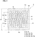
- a bipolar plate 2 provided with a flow path 10 having a non-interlocking type opposed comb-tooth shape shown in Fig. 3 will be described.
- the non-interlocking type opposed comb-tooth shape is a shape in which a comb-tooth-shaped path of an introducing path 12 and a comb-tooth-shaped path of a discharging path 14 are arranged to face each other without being interlocked with each other.
- the basic structure of the bipolar plate 2 is the same as that of the bipolar plate 1 according to Embodiment 1, and only the form of the flow path 10 is different.
- the introducing path 12 includes an introduction port 12i, an introduction-side horizontal groove section 12x which extends in the horizontal direction of the bipolar plate 2 (in the leftward/rightward direction in Fig. 3 ), and a plurality of introduction-side vertical groove sections 12y which extend from the introduction-side horizontal groove section 12x in the longitudinal direction of the bipolar plate 2 (in the upward/downward direction in Fig. 3 ) and are arranged in parallel with a predetermined distance therebetween.
- the number of the introduction-side vertical groove sections 12y of the bipolar plate 2 is larger than the number of the introduction-side vertical groove sections 12y of the bipolar plate 1, and the introduction-side vertical groove sections 12y of the bipolar plate 2 have a smaller length than the introduction-side vertical groove sections 12y of the bipolar plate 1.
- the introduction port 12i, the introduction-side horizontal groove section 12x, and the introduction-side vertical groove sections 12y are continuous.
- the discharging path 14 has the same shape as that of the introducing path 12.
- the discharging path 14 includes a discharge port 14o, a discharge-side horizontal groove section 14x which extends in the horizontal direction of the bipolar plate 2, and a plurality of discharge-side vertical groove sections 14y which extend from the discharge-side horizontal groove section 14x in the longitudinal direction of the bipolar plate 2 and are arranged in parallel with a predetermined distance therebetween.
- the number of the discharge-side vertical groove sections 14y of the bipolar plate 2 is larger than the number of the discharge-side vertical groove sections 14y of the bipolar plate 1, and the discharge-side vertical groove sections 14y of the bipolar plate 2 have a smaller length than the discharge-side vertical groove sections 14y of the bipolar plate 1.
- the number of the discharge-side vertical groove sections 14y is the same as the number of the introduction-side vertical groove sections 12y. Furthermore, the length Lyo of the discharge-side vertical groove section 14y is the same as the length Lyi of the introduction-side vertical groove section 12y.
- the discharge port 14o, the discharge-side horizontal groove section 14x, and the discharge-side vertical groove sections 14y are continuous.
- the introduction-side vertical groove sections 12y and the discharge-side vertical groove sections 14y are arranged symmetrically in the upward/downward direction. Accordingly, adjacent vertical groove sections are introduction-side vertical groove sections 12y or discharge-side vertical groove sections 14y.
- the introduction-side vertical groove sections 12y and the discharge-side vertical groove sections 14y are each disposed so as to extend in the vertical direction (in the upward/downward direction in Fig. 3 ), and also, the introduction-side vertical groove sections 12y are arranged in parallel to each other and the discharge-side vertical groove sections 14y are arranged in parallel to each other in a direction orthogonal to the vertical direction.
- the introduction-side vertical groove sections 12y and the discharge-side vertical groove sections 14y are arranged symmetrically in the upward/downward direction, and the ratio of the total length (Lyi + Lyo) of the length Lyi of the introduction-side vertical groove section 12y and the length Lyo of the discharge-side vertical groove section 14y to a length Lh in the vertical direction of the bipolar plate 2, i.e., [(Lyi + Lyo)/Lh)] ⁇ 100, may be 70% to 99%, or further 75% to 99%.
- the electrolyte introduced from the introduction port 12i flows along the groove section 11 (in directions indicated by solid-line arrows in Fig. 3 ), flows to traverse over ridge portions 16 located between the introduction-side vertical groove sections 12y and ridge portions 16 located between the discharge-side vertical groove sections 14y (in directions indicated by slanting broken-line arrows in Fig. 3 ), and flows to traverse over a ridge portion 16 located between the introduction-side vertical groove sections 12y of the introducing path 12 and the discharge-side vertical groove sections 14y of the discharging path 14 (in the longitudinal direction indicated by broken-line arrows in Fig. 3 ).
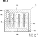
- Embodiment 3 a bipolar plate 3 provided with a flow path 10 having a continuous grid shape shown in Fig. 4 will be described.
- the grid shape refers to the shape in which an introducing path and a discharging path are in communication with each other.
- the basic structure of the bipolar plate 3 is the same as that of the bipolar plate 1 according to Embodiment 1, and only the form of the flow path 10 is different.
- the flow path 10 includes, as a groove section 11, a plurality of vertical groove sections 18y which extend in the longitudinal direction of the bipolar plate 3 (in the upward/downward direction in Fig. 4 ) and are arranged in parallel with a predetermined distance therebetween and a pair of horizontal groove sections 18x which connect introduction-side ends of the vertical groove sections 18y and discharge-side ends of the vertical groove sections 18y.
- the introduction-side horizontal groove section 18x (on the lower side in Fig. 4 ) is connected to an introduction port 12i at one end thereof (on the right side in Fig. 4 ) and is connected to a discharge port 14o at the other end thereof (on the left side in Fig. 4 ) through a vertical groove section 18y.
- the discharge-side horizontal groove section 18x (on the upper side in Fig. 4 ) is connected to the discharge port 14o at one end thereof (on the left side in Fig. 4 ) and is connected to the introduction port 12i at the other end thereof (on the right side in Fig. 4 ) through a vertical groove section 18y.
- the introduction port 12i, a pair of horizontal groove sections 18x, the vertical groove sections 18y, and the discharge port 14o are continuous.
- the electrolyte introduced from the introduction port 12i flows along the groove section 11 (in directions indicated by solid-line arrows in Fig. 4 ) and flows to traverse between the vertical groove sections 18y over ridge portions 16 located between the vertical groove sections 18y (in directions indicated by broken-line arrows).
- the electrolyte introduced from the introduction port 12i flows along the groove section 11 (in directions indicated by solid-line arrows in Fig. 4 ) and flows to traverse between the vertical groove sections 18y over ridge portions 16 located between the vertical groove sections 18y (in directions indicated by broken-line arrows).
- a bipolar plate 4 provided with a flow path 10 having a discontinuous shape shown in Fig. 5 will be described.
- the bipolar plate 4 is configured such that the introduction-side vertical groove sections 12y and the discharge-side vertical groove sections 14y in the bipolar plate 1 ( Fig. 1 ) described in Embodiment 1 are discontinuously (non-continuously) formed.
- battery reactions in the electrode can be conducted such that the electrolyte traverses not only over the ridge portions 16 in the width direction but over ridge portions 16 between adjacent vertical groove sections in the longitudinal direction between the vertical groove sections, and it is anticipated that the amount of reaction current in the electrode can be increased.
- the continuous meander shape refers to the shape in which a groove section 11 is continuously formed from an introduction port 12i to a discharge port 14o.
- the groove section 11 includes a plurality of vertical groove sections 19y which are arranged in parallel and a plurality of short horizontal groove sections 19x which connect one ends of the vertical groove sections 19y to each other or the other ends of the vertical groove sections 19y to each other alternately.
- the electrolyte introduced from the introduction port 12i flows along the groove section 11 (in directions indicated by solid-line arrows in Fig. 6 ) and flows to traverse between vertical groove sections 19y over ridge portions 16 located between the vertical groove sections 19y.
- the electrolyte introduced from the introduction port 12i flows along the groove section 11 (in directions indicated by solid-line arrows in Fig. 6 ) and flows to traverse between vertical groove sections 19y over ridge portions 16 located between the vertical groove sections 19y.
- a redox-flow battery which includes a cell stack including a plurality of layered bodies which are stacked, each layered body including the cell frame, a positive electrode, a membrane, and a negative electrode stacked in this order, will be described with reference to Fig. 11 . Since the redox-flow battery includes the cell stack according to the embodiment of the present invention, the flow resistance of the electrolyte in the battery cell can be decreased, and it is possible to suppress a decrease in the battery reaction area in the electrode. Accordingly, the internal resistance of the battery can be decreased.
- Test Example 1 regarding an RF battery in which a bipolar plate provided with a flow path having an interlocking type comb-tooth shape was placed at a predetermined position, a battery cell was actually produced and the internal resistance of the RF battery was checked.
- two types of RF battery were produced: i.e., Sample No. 1-1 in which a bipolar plate provided with a flow path having a vertical groove structure was used and Sample No. 1-11 in which a bipolar plate provided with a flow path having a horizontal groove structure was used. Specifications of the RF batteries used are shown below.
- RF batteries having a single-cell structure were produced in which a battery cell including a positive electrode-membrane-negative electrode stack was sandwiched between cell frames including bipolar plates. Accordingly, the internal resistance of the RF battery is shown as cell resistivity.
- Introducing path including an introduction port, a vertical groove section which extends in the longitudinal direction of the bipolar plate (in the vertical direction), and a plurality of horizontal groove sections which extend from the vertical groove section in the horizontal direction of the bipolar plate (in a direction orthogonal to the vertical direction) and are arranged in parallel with a predetermined distance therebetween.
- Discharging path including a discharge port, a vertical groove section which extends in the longitudinal direction of the bipolar plate (in the vertical direction), and a plurality of horizontal groove sections which extend from the vertical groove section in the horizontal direction of the bipolar plate (in a direction orthogonal to the vertical direction) and are arranged in parallel with a predetermined distance therebetween.
- introduction port introduction-side vertical groove section ⁇ introduction-side horizontal groove sections ⁇ discharge-side horizontal groove sections ⁇ discharge-side vertical groove section ⁇ discharge port
Applications Claiming Priority (2)
| Application Number | Priority Date | Filing Date | Title |
|---|---|---|---|
| JP2015125352 | 2015-06-23 | ||
| PCT/JP2016/067914 WO2016208482A1 (ja) | 2015-06-23 | 2016-06-16 | 双極板、セルフレーム及びセルスタック、並びにレドックスフロー電池 |
Publications (3)
| Publication Number | Publication Date |
|---|---|
| EP3316376A1 true EP3316376A1 (de) | 2018-05-02 |
| EP3316376A4 EP3316376A4 (de) | 2018-05-30 |
| EP3316376B1 EP3316376B1 (de) | 2020-07-22 |
Family
ID=57585118
Family Applications (1)
| Application Number | Title | Priority Date | Filing Date |
|---|---|---|---|
| EP16814253.7A Active EP3316376B1 (de) | 2015-06-23 | 2016-06-16 | Bipolarplatte, zellenrahmen, zellenstapel und redox-durchflussbatterie |
Country Status (8)
| Country | Link |
|---|---|
| US (1) | US10593964B2 (de) |
| EP (1) | EP3316376B1 (de) |
| JP (1) | JP6819885B2 (de) |
| KR (1) | KR20180020165A (de) |
| CN (1) | CN107710487B (de) |
| AU (1) | AU2016284157B2 (de) |
| TW (1) | TWI696312B (de) |
| WO (1) | WO2016208482A1 (de) |
Families Citing this family (11)
| Publication number | Priority date | Publication date | Assignee | Title |
|---|---|---|---|---|
| WO2018116467A1 (ja) * | 2016-12-22 | 2018-06-28 | 住友電気工業株式会社 | セルフレーム、セルスタック、およびレドックスフロー電池 |
| US11631867B2 (en) | 2017-01-19 | 2023-04-18 | Sumitomo Electric Industries, Ltd. | Bipolar plate, cell frame, cell stack and redox flow battery |
| US11367880B2 (en) | 2017-07-13 | 2022-06-21 | Sumitomo Electric Industries, Ltd. | Bipolar plate, cell frame, battery cell, cell stack, and redox flow battery |
| JP6908031B2 (ja) * | 2017-09-08 | 2021-07-21 | 住友電気工業株式会社 | レドックスフロー電池セル、レドックスフロー電池セルスタック、及びレドックスフロー電池 |
| IT201800004325A1 (it) * | 2018-04-09 | 2019-10-09 | Batteria a flusso | |
| CN111224144B (zh) * | 2018-11-26 | 2024-04-16 | 中国科学院大连化学物理研究所 | 一种液流电池电堆结构及其应用 |
| CN109860665B (zh) * | 2019-01-21 | 2020-08-21 | 西安交通大学 | 一种低泵功液流电池及其工作方法 |
| JP7281094B2 (ja) * | 2019-02-14 | 2023-05-25 | 住友電気工業株式会社 | 双極板、セルフレーム、セルスタック、およびレドックスフロー電池 |
| CN110690488A (zh) * | 2019-11-13 | 2020-01-14 | 上海海事大学 | 一种液流电池 |
| JP7461614B2 (ja) | 2020-09-29 | 2024-04-04 | 住友電気工業株式会社 | 双極板、セルフレーム、電池セル、セルスタック、及びレドックスフロー電池 |
| CN117374293B (zh) * | 2023-12-07 | 2024-03-08 | 北京普能世纪科技有限公司 | 一体化电极和包含其的液流电池 |
Family Cites Families (19)
| Publication number | Priority date | Publication date | Assignee | Title |
|---|---|---|---|---|
| JP3642697B2 (ja) * | 1999-03-05 | 2005-04-27 | 住友電気工業株式会社 | 流体流通型電池用セル |
| JP3682244B2 (ja) | 2001-06-12 | 2005-08-10 | 住友電気工業株式会社 | レドックスフロー電池用セルフレーム及びレドックスフロー電池 |
| DK2514015T3 (en) * | 2009-12-18 | 2015-07-20 | United Technologies Corp | CURRENT BATTERY WITH COMPLETE CURRENT FIELD |
| KR20130009750A (ko) * | 2010-01-25 | 2013-01-23 | 라모트 앳 텔-아비브 유니버시티 리미티드 | 전기화학 시스템 및 이의 작동 방법 |
| US9123962B2 (en) * | 2011-02-07 | 2015-09-01 | United Technologies Corporation | Flow battery having electrodes with a plurality of different pore sizes and or different layers |
| US20130029196A1 (en) * | 2011-07-29 | 2013-01-31 | Pratt & Whitney Rocketdyne, Inc. | Flow battery cells arranged between an inlet manifold and an outlet manifold |
| EP2795697B1 (de) * | 2011-12-20 | 2020-11-04 | United Technologies Corporation | Durchflussbatterie mit gemischtem durchfluss |
| CN103579658B (zh) * | 2012-08-03 | 2016-01-06 | 上海神力科技有限公司 | 一种液流电池堆 |
| US9685651B2 (en) * | 2012-09-05 | 2017-06-20 | Ess Tech, Inc. | Internally manifolded flow cell for an all-iron hybrid flow battery |
| CN103094600B (zh) * | 2013-01-31 | 2015-09-23 | 中国东方电气集团有限公司 | 一种液流半电池和具有其的液流电池堆 |
| GB2515994A (en) | 2013-04-08 | 2015-01-14 | Acal Energy Ltd | Fuel cells |
| JP2014207122A (ja) * | 2013-04-12 | 2014-10-30 | パナソニック株式会社 | 双極板及びその製造方法 |
| WO2014205494A1 (en) * | 2013-06-27 | 2014-12-31 | Eden Research And Development Pty Ltd | Laminar flow battery |
| JP6103386B2 (ja) * | 2014-01-24 | 2017-03-29 | 住友電気工業株式会社 | レドックスフロー電池 |
| JP6201876B2 (ja) * | 2014-04-23 | 2017-09-27 | 住友電気工業株式会社 | 双極板、レドックスフロー電池、及び双極板の製造方法 |
| JP6108008B1 (ja) * | 2016-05-30 | 2017-04-05 | 住友電気工業株式会社 | 双極板、セルフレーム及びセルスタック、並びにレドックスフロー電池 |
| WO2018069996A1 (ja) * | 2016-10-12 | 2018-04-19 | 住友電気工業株式会社 | 双極板、セルフレーム、セルスタック、及びレドックスフロー電池 |
| WO2018092215A1 (ja) * | 2016-11-16 | 2018-05-24 | 住友電気工業株式会社 | セルフレーム、セルスタック、及びレドックスフロー電池 |
| JP6696696B2 (ja) * | 2017-03-21 | 2020-05-20 | 株式会社東芝 | 電気化学反応装置 |
-
2016
- 2016-06-16 JP JP2017525290A patent/JP6819885B2/ja active Active
- 2016-06-16 US US15/738,703 patent/US10593964B2/en active Active
- 2016-06-16 WO PCT/JP2016/067914 patent/WO2016208482A1/ja active Application Filing
- 2016-06-16 EP EP16814253.7A patent/EP3316376B1/de active Active
- 2016-06-16 CN CN201680036292.1A patent/CN107710487B/zh active Active
- 2016-06-16 AU AU2016284157A patent/AU2016284157B2/en active Active
- 2016-06-16 KR KR1020177036684A patent/KR20180020165A/ko unknown
- 2016-06-23 TW TW105119757A patent/TWI696312B/zh active
Also Published As
| Publication number | Publication date |
|---|---|
| CN107710487A (zh) | 2018-02-16 |
| AU2016284157B2 (en) | 2020-11-19 |
| TW201711262A (zh) | 2017-03-16 |
| EP3316376A4 (de) | 2018-05-30 |
| CN107710487B (zh) | 2021-03-16 |
| EP3316376B1 (de) | 2020-07-22 |
| US10593964B2 (en) | 2020-03-17 |
| WO2016208482A1 (ja) | 2016-12-29 |
| JP6819885B2 (ja) | 2021-01-27 |
| TWI696312B (zh) | 2020-06-11 |
| AU2016284157A1 (en) | 2018-01-18 |
| US20180190999A1 (en) | 2018-07-05 |
| JPWO2016208482A1 (ja) | 2018-04-12 |
| KR20180020165A (ko) | 2018-02-27 |
Similar Documents
| Publication | Publication Date | Title |
|---|---|---|
| EP3316376B1 (de) | Bipolarplatte, zellenrahmen, zellenstapel und redox-durchflussbatterie | |
| CN108352554B (zh) | 双极板、电池框架、电池堆以及氧化还原液流电池 | |
| EP3136490B1 (de) | Bipolarplatte, redox-durchflussbatterie und verfahren zur herstellung einer bipolaren platte | |
| US10211467B2 (en) | Cell frame for redox flow battery, cell stack for redox flow battery, and redox flow battery | |
| US20180159163A1 (en) | Redox flow battery | |
| KR102382373B1 (ko) | 전지 셀 및 레독스 플로우 전지 | |
| AU2016342919B2 (en) | Redox flow battery electrode, and redox flow battery | |
| KR20170034995A (ko) | 플로우 프레임 및 그를 갖는 레독스 플로우 이차전지 | |
| US11769886B2 (en) | Battery cell, cell stack, and redox flow battery | |
| KR102058504B1 (ko) | 대면적형 레독스 흐름전지 | |
| US11811105B2 (en) | Battery cell, cell stack, and redox flow battery | |
| JP7461614B2 (ja) | 双極板、セルフレーム、電池セル、セルスタック、及びレドックスフロー電池 | |
| KR20200116557A (ko) | 셀 프레임, 전지 셀, 셀 스택, 및 레독스 플로우 전지 | |
| JP2020129502A (ja) | 電池セル、セルスタック、及びレドックスフロー電池 | |
| JPWO2019234867A1 (ja) | 双極板、セルフレーム、セルスタック、及びレドックスフロー電池 |
Legal Events
| Date | Code | Title | Description |
|---|---|---|---|
| STAA | Information on the status of an ep patent application or granted ep patent |
Free format text: STATUS: THE INTERNATIONAL PUBLICATION HAS BEEN MADE |
|
| PUAI | Public reference made under article 153(3) epc to a published international application that has entered the european phase |
Free format text: ORIGINAL CODE: 0009012 |
|
| STAA | Information on the status of an ep patent application or granted ep patent |
Free format text: STATUS: REQUEST FOR EXAMINATION WAS MADE |
|
| 17P | Request for examination filed |
Effective date: 20171220 |
|
| AK | Designated contracting states |
Kind code of ref document: A1 Designated state(s): AL AT BE BG CH CY CZ DE DK EE ES FI FR GB GR HR HU IE IS IT LI LT LU LV MC MK MT NL NO PL PT RO RS SE SI SK SM TR |
|
| AX | Request for extension of the european patent |
Extension state: BA ME |
|
| RIC1 | Information provided on ipc code assigned before grant |
Ipc: H01M 8/0258 20160101ALI20180418BHEP Ipc: H01M 8/0273 20160101ALN20180418BHEP Ipc: H01M 8/02 20160101ALI20180418BHEP Ipc: H01M 8/026 20160101ALI20180418BHEP Ipc: H01M 8/18 20060101AFI20180418BHEP |
|
| A4 | Supplementary search report drawn up and despatched |
Effective date: 20180504 |
|
| DAV | Request for validation of the european patent (deleted) | ||
| DAX | Request for extension of the european patent (deleted) | ||
| STAA | Information on the status of an ep patent application or granted ep patent |
Free format text: STATUS: EXAMINATION IS IN PROGRESS |
|
| 17Q | First examination report despatched |
Effective date: 20190301 |
|
| GRAP | Despatch of communication of intention to grant a patent |
Free format text: ORIGINAL CODE: EPIDOSNIGR1 |
|
| STAA | Information on the status of an ep patent application or granted ep patent |
Free format text: STATUS: GRANT OF PATENT IS INTENDED |
|
| RIC1 | Information provided on ipc code assigned before grant |
Ipc: H01M 8/0273 20160101ALN20200128BHEP Ipc: H01M 8/02 20160101ALI20200128BHEP Ipc: H01M 8/18 20060101AFI20200128BHEP Ipc: H01M 8/026 20160101ALI20200128BHEP Ipc: H01M 8/0258 20160101ALI20200128BHEP |
|
| INTG | Intention to grant announced |
Effective date: 20200214 |
|
| RIC1 | Information provided on ipc code assigned before grant |
Ipc: H01M 8/0258 20160101ALI20200131BHEP Ipc: H01M 8/18 20060101AFI20200131BHEP Ipc: H01M 8/026 20160101ALI20200131BHEP Ipc: H01M 8/0273 20160101ALN20200131BHEP Ipc: H01M 8/02 20160101ALI20200131BHEP |
|
| GRAS | Grant fee paid |
Free format text: ORIGINAL CODE: EPIDOSNIGR3 |
|
| GRAA | (expected) grant |
Free format text: ORIGINAL CODE: 0009210 |
|
| STAA | Information on the status of an ep patent application or granted ep patent |
Free format text: STATUS: THE PATENT HAS BEEN GRANTED |
|
| AK | Designated contracting states |
Kind code of ref document: B1 Designated state(s): AL AT BE BG CH CY CZ DE DK EE ES FI FR GB GR HR HU IE IS IT LI LT LU LV MC MK MT NL NO PL PT RO RS SE SI SK SM TR |
|
| REG | Reference to a national code |
Ref country code: GB Ref legal event code: FG4D |
|
| REG | Reference to a national code |
Ref country code: DE Ref legal event code: R082 Ref document number: 602016040536 Country of ref document: DE Representative=s name: BOULT WADE TENNANT LLP, DE |
|
| REG | Reference to a national code |
Ref country code: CH Ref legal event code: EP |
|
| REG | Reference to a national code |
Ref country code: DE Ref legal event code: R096 Ref document number: 602016040536 Country of ref document: DE |
|
| REG | Reference to a national code |
Ref country code: AT Ref legal event code: REF Ref document number: 1294246 Country of ref document: AT Kind code of ref document: T Effective date: 20200815 |
|
| REG | Reference to a national code |
Ref country code: IE Ref legal event code: FG4D |
|
| REG | Reference to a national code |
Ref country code: LT Ref legal event code: MG4D |
|
| REG | Reference to a national code |
Ref country code: AT Ref legal event code: MK05 Ref document number: 1294246 Country of ref document: AT Kind code of ref document: T Effective date: 20200722 |
|
| PG25 | Lapsed in a contracting state [announced via postgrant information from national office to epo] |
Ref country code: ES Free format text: LAPSE BECAUSE OF FAILURE TO SUBMIT A TRANSLATION OF THE DESCRIPTION OR TO PAY THE FEE WITHIN THE PRESCRIBED TIME-LIMIT Effective date: 20200722 Ref country code: SE Free format text: LAPSE BECAUSE OF FAILURE TO SUBMIT A TRANSLATION OF THE DESCRIPTION OR TO PAY THE FEE WITHIN THE PRESCRIBED TIME-LIMIT Effective date: 20200722 Ref country code: HR Free format text: LAPSE BECAUSE OF FAILURE TO SUBMIT A TRANSLATION OF THE DESCRIPTION OR TO PAY THE FEE WITHIN THE PRESCRIBED TIME-LIMIT Effective date: 20200722 Ref country code: LT Free format text: LAPSE BECAUSE OF FAILURE TO SUBMIT A TRANSLATION OF THE DESCRIPTION OR TO PAY THE FEE WITHIN THE PRESCRIBED TIME-LIMIT Effective date: 20200722 Ref country code: PT Free format text: LAPSE BECAUSE OF FAILURE TO SUBMIT A TRANSLATION OF THE DESCRIPTION OR TO PAY THE FEE WITHIN THE PRESCRIBED TIME-LIMIT Effective date: 20201123 Ref country code: FI Free format text: LAPSE BECAUSE OF FAILURE TO SUBMIT A TRANSLATION OF THE DESCRIPTION OR TO PAY THE FEE WITHIN THE PRESCRIBED TIME-LIMIT Effective date: 20200722 Ref country code: BG Free format text: LAPSE BECAUSE OF FAILURE TO SUBMIT A TRANSLATION OF THE DESCRIPTION OR TO PAY THE FEE WITHIN THE PRESCRIBED TIME-LIMIT Effective date: 20201022 Ref country code: NO Free format text: LAPSE BECAUSE OF FAILURE TO SUBMIT A TRANSLATION OF THE DESCRIPTION OR TO PAY THE FEE WITHIN THE PRESCRIBED TIME-LIMIT Effective date: 20201022 Ref country code: GR Free format text: LAPSE BECAUSE OF FAILURE TO SUBMIT A TRANSLATION OF THE DESCRIPTION OR TO PAY THE FEE WITHIN THE PRESCRIBED TIME-LIMIT Effective date: 20201023 Ref country code: AT Free format text: LAPSE BECAUSE OF FAILURE TO SUBMIT A TRANSLATION OF THE DESCRIPTION OR TO PAY THE FEE WITHIN THE PRESCRIBED TIME-LIMIT Effective date: 20200722 |
|
| PG25 | Lapsed in a contracting state [announced via postgrant information from national office to epo] |
Ref country code: RS Free format text: LAPSE BECAUSE OF FAILURE TO SUBMIT A TRANSLATION OF THE DESCRIPTION OR TO PAY THE FEE WITHIN THE PRESCRIBED TIME-LIMIT Effective date: 20200722 Ref country code: PL Free format text: LAPSE BECAUSE OF FAILURE TO SUBMIT A TRANSLATION OF THE DESCRIPTION OR TO PAY THE FEE WITHIN THE PRESCRIBED TIME-LIMIT Effective date: 20200722 Ref country code: LV Free format text: LAPSE BECAUSE OF FAILURE TO SUBMIT A TRANSLATION OF THE DESCRIPTION OR TO PAY THE FEE WITHIN THE PRESCRIBED TIME-LIMIT Effective date: 20200722 Ref country code: IS Free format text: LAPSE BECAUSE OF FAILURE TO SUBMIT A TRANSLATION OF THE DESCRIPTION OR TO PAY THE FEE WITHIN THE PRESCRIBED TIME-LIMIT Effective date: 20201122 |
|
| PG25 | Lapsed in a contracting state [announced via postgrant information from national office to epo] |
Ref country code: NL Free format text: LAPSE BECAUSE OF FAILURE TO SUBMIT A TRANSLATION OF THE DESCRIPTION OR TO PAY THE FEE WITHIN THE PRESCRIBED TIME-LIMIT Effective date: 20200722 |
|
| REG | Reference to a national code |
Ref country code: DE Ref legal event code: R097 Ref document number: 602016040536 Country of ref document: DE |
|
| PG25 | Lapsed in a contracting state [announced via postgrant information from national office to epo] |
Ref country code: EE Free format text: LAPSE BECAUSE OF FAILURE TO SUBMIT A TRANSLATION OF THE DESCRIPTION OR TO PAY THE FEE WITHIN THE PRESCRIBED TIME-LIMIT Effective date: 20200722 Ref country code: SM Free format text: LAPSE BECAUSE OF FAILURE TO SUBMIT A TRANSLATION OF THE DESCRIPTION OR TO PAY THE FEE WITHIN THE PRESCRIBED TIME-LIMIT Effective date: 20200722 Ref country code: RO Free format text: LAPSE BECAUSE OF FAILURE TO SUBMIT A TRANSLATION OF THE DESCRIPTION OR TO PAY THE FEE WITHIN THE PRESCRIBED TIME-LIMIT Effective date: 20200722 Ref country code: DK Free format text: LAPSE BECAUSE OF FAILURE TO SUBMIT A TRANSLATION OF THE DESCRIPTION OR TO PAY THE FEE WITHIN THE PRESCRIBED TIME-LIMIT Effective date: 20200722 Ref country code: CZ Free format text: LAPSE BECAUSE OF FAILURE TO SUBMIT A TRANSLATION OF THE DESCRIPTION OR TO PAY THE FEE WITHIN THE PRESCRIBED TIME-LIMIT Effective date: 20200722 |
|
| PLBE | No opposition filed within time limit |
Free format text: ORIGINAL CODE: 0009261 |
|
| STAA | Information on the status of an ep patent application or granted ep patent |
Free format text: STATUS: NO OPPOSITION FILED WITHIN TIME LIMIT |
|
| PG25 | Lapsed in a contracting state [announced via postgrant information from national office to epo] |
Ref country code: AL Free format text: LAPSE BECAUSE OF FAILURE TO SUBMIT A TRANSLATION OF THE DESCRIPTION OR TO PAY THE FEE WITHIN THE PRESCRIBED TIME-LIMIT Effective date: 20200722 |
|
| 26N | No opposition filed |
Effective date: 20210423 |
|
| PG25 | Lapsed in a contracting state [announced via postgrant information from national office to epo] |
Ref country code: SK Free format text: LAPSE BECAUSE OF FAILURE TO SUBMIT A TRANSLATION OF THE DESCRIPTION OR TO PAY THE FEE WITHIN THE PRESCRIBED TIME-LIMIT Effective date: 20200722 |
|
| PG25 | Lapsed in a contracting state [announced via postgrant information from national office to epo] |
Ref country code: SI Free format text: LAPSE BECAUSE OF FAILURE TO SUBMIT A TRANSLATION OF THE DESCRIPTION OR TO PAY THE FEE WITHIN THE PRESCRIBED TIME-LIMIT Effective date: 20200722 |
|
| REG | Reference to a national code |
Ref country code: NL Ref legal event code: MP Effective date: 20200722 |
|
| PG25 | Lapsed in a contracting state [announced via postgrant information from national office to epo] |
Ref country code: MC Free format text: LAPSE BECAUSE OF FAILURE TO SUBMIT A TRANSLATION OF THE DESCRIPTION OR TO PAY THE FEE WITHIN THE PRESCRIBED TIME-LIMIT Effective date: 20200722 |
|
| REG | Reference to a national code |
Ref country code: CH Ref legal event code: PL |
|
| REG | Reference to a national code |
Ref country code: BE Ref legal event code: MM Effective date: 20210630 |
|
| PG25 | Lapsed in a contracting state [announced via postgrant information from national office to epo] |
Ref country code: LU Free format text: LAPSE BECAUSE OF NON-PAYMENT OF DUE FEES Effective date: 20210616 |
|
| PG25 | Lapsed in a contracting state [announced via postgrant information from national office to epo] |
Ref country code: LI Free format text: LAPSE BECAUSE OF NON-PAYMENT OF DUE FEES Effective date: 20210630 Ref country code: IE Free format text: LAPSE BECAUSE OF NON-PAYMENT OF DUE FEES Effective date: 20210616 Ref country code: CH Free format text: LAPSE BECAUSE OF NON-PAYMENT OF DUE FEES Effective date: 20210630 |
|
| PG25 | Lapsed in a contracting state [announced via postgrant information from national office to epo] |
Ref country code: BE Free format text: LAPSE BECAUSE OF NON-PAYMENT OF DUE FEES Effective date: 20210630 |
|
| P01 | Opt-out of the competence of the unified patent court (upc) registered |
Effective date: 20230515 |
|
| PG25 | Lapsed in a contracting state [announced via postgrant information from national office to epo] |
Ref country code: CY Free format text: LAPSE BECAUSE OF FAILURE TO SUBMIT A TRANSLATION OF THE DESCRIPTION OR TO PAY THE FEE WITHIN THE PRESCRIBED TIME-LIMIT Effective date: 20200722 |
|
| PG25 | Lapsed in a contracting state [announced via postgrant information from national office to epo] |
Ref country code: HU Free format text: LAPSE BECAUSE OF FAILURE TO SUBMIT A TRANSLATION OF THE DESCRIPTION OR TO PAY THE FEE WITHIN THE PRESCRIBED TIME-LIMIT; INVALID AB INITIO Effective date: 20160616 |
|
| PGFP | Annual fee paid to national office [announced via postgrant information from national office to epo] |
Ref country code: IT Payment date: 20230510 Year of fee payment: 8 Ref country code: FR Payment date: 20230510 Year of fee payment: 8 Ref country code: DE Payment date: 20230502 Year of fee payment: 8 |
|
| PGFP | Annual fee paid to national office [announced via postgrant information from national office to epo] |
Ref country code: GB Payment date: 20230427 Year of fee payment: 8 |
|
| PG25 | Lapsed in a contracting state [announced via postgrant information from national office to epo] |
Ref country code: MK Free format text: LAPSE BECAUSE OF FAILURE TO SUBMIT A TRANSLATION OF THE DESCRIPTION OR TO PAY THE FEE WITHIN THE PRESCRIBED TIME-LIMIT Effective date: 20200722 |