EP3315760B1 - Flow rate control valve and high-pressure fuel supply pump - Google Patents
Flow rate control valve and high-pressure fuel supply pump Download PDFInfo
- Publication number
- EP3315760B1 EP3315760B1 EP16814130.7A EP16814130A EP3315760B1 EP 3315760 B1 EP3315760 B1 EP 3315760B1 EP 16814130 A EP16814130 A EP 16814130A EP 3315760 B1 EP3315760 B1 EP 3315760B1
- Authority
- EP
- European Patent Office
- Prior art keywords
- fixed core
- valve
- fuel
- suction
- circumferential side
- Prior art date
- Legal status (The legal status is an assumption and is not a legal conclusion. Google has not performed a legal analysis and makes no representation as to the accuracy of the status listed.)
- Active
Links
- 239000000446 fuel Substances 0.000 title claims description 218
- 230000001105 regulatory effect Effects 0.000 claims description 5
- 238000007599 discharging Methods 0.000 claims description 4
- 238000000034 method Methods 0.000 description 85
- 230000008569 process Effects 0.000 description 80
- 230000004907 flux Effects 0.000 description 60
- 230000002829 reductive effect Effects 0.000 description 44
- 230000033001 locomotion Effects 0.000 description 41
- 230000007246 mechanism Effects 0.000 description 40
- 230000007423 decrease Effects 0.000 description 26
- 230000004043 responsiveness Effects 0.000 description 24
- 238000002485 combustion reaction Methods 0.000 description 18
- 239000012530 fluid Substances 0.000 description 17
- 239000000463 material Substances 0.000 description 16
- 230000002159 abnormal effect Effects 0.000 description 15
- 230000006870 function Effects 0.000 description 15
- 230000003628 erosive effect Effects 0.000 description 13
- 230000010349 pulsation Effects 0.000 description 12
- 238000009434 installation Methods 0.000 description 11
- 238000010586 diagram Methods 0.000 description 10
- 230000000694 effects Effects 0.000 description 10
- 230000035699 permeability Effects 0.000 description 10
- 230000000630 rising effect Effects 0.000 description 10
- LFQSCWFLJHTTHZ-UHFFFAOYSA-N Ethanol Chemical compound CCO LFQSCWFLJHTTHZ-UHFFFAOYSA-N 0.000 description 8
- 238000010791 quenching Methods 0.000 description 8
- 230000000171 quenching effect Effects 0.000 description 8
- 238000005299 abrasion Methods 0.000 description 7
- 230000008859 change Effects 0.000 description 7
- 238000007906 compression Methods 0.000 description 7
- 238000006073 displacement reaction Methods 0.000 description 7
- 238000010008 shearing Methods 0.000 description 7
- 229910001220 stainless steel Inorganic materials 0.000 description 7
- 239000002184 metal Substances 0.000 description 6
- 229910052751 metal Inorganic materials 0.000 description 6
- 239000010935 stainless steel Substances 0.000 description 6
- 238000011144 upstream manufacturing Methods 0.000 description 6
- 230000001276 controlling effect Effects 0.000 description 5
- 238000005260 corrosion Methods 0.000 description 5
- 230000007797 corrosion Effects 0.000 description 5
- 238000010438 heat treatment Methods 0.000 description 5
- NJPPVKZQTLUDBO-UHFFFAOYSA-N novaluron Chemical compound C1=C(Cl)C(OC(F)(F)C(OC(F)(F)F)F)=CC=C1NC(=O)NC(=O)C1=C(F)C=CC=C1F NJPPVKZQTLUDBO-UHFFFAOYSA-N 0.000 description 5
- 238000003466 welding Methods 0.000 description 5
- 229910000963 austenitic stainless steel Inorganic materials 0.000 description 4
- 230000006835 compression Effects 0.000 description 4
- 230000006866 deterioration Effects 0.000 description 4
- 238000003825 pressing Methods 0.000 description 4
- 230000009467 reduction Effects 0.000 description 4
- RYGMFSIKBFXOCR-UHFFFAOYSA-N Copper Chemical compound [Cu] RYGMFSIKBFXOCR-UHFFFAOYSA-N 0.000 description 3
- XEEYBQQBJWHFJM-UHFFFAOYSA-N Iron Chemical group [Fe] XEEYBQQBJWHFJM-UHFFFAOYSA-N 0.000 description 3
- 238000004299 exfoliation Methods 0.000 description 3
- 239000003502 gasoline Substances 0.000 description 3
- 238000002347 injection Methods 0.000 description 3
- 239000007924 injection Substances 0.000 description 3
- 238000003754 machining Methods 0.000 description 3
- 239000000696 magnetic material Substances 0.000 description 3
- 229910001105 martensitic stainless steel Inorganic materials 0.000 description 3
- 230000003068 static effect Effects 0.000 description 3
- XKRFYHLGVUSROY-UHFFFAOYSA-N Argon Chemical compound [Ar] XKRFYHLGVUSROY-UHFFFAOYSA-N 0.000 description 2
- 238000005255 carburizing Methods 0.000 description 2
- 210000000078 claw Anatomy 0.000 description 2
- 238000005520 cutting process Methods 0.000 description 2
- 230000003247 decreasing effect Effects 0.000 description 2
- 230000003111 delayed effect Effects 0.000 description 2
- 239000002828 fuel tank Substances 0.000 description 2
- 230000006872 improvement Effects 0.000 description 2
- 230000005389 magnetism Effects 0.000 description 2
- 230000036961 partial effect Effects 0.000 description 2
- 230000000149 penetrating effect Effects 0.000 description 2
- 238000007747 plating Methods 0.000 description 2
- 238000004080 punching Methods 0.000 description 2
- 230000004044 response Effects 0.000 description 2
- 239000000126 substance Substances 0.000 description 2
- 229910000859 α-Fe Inorganic materials 0.000 description 2
- 229910001369 Brass Inorganic materials 0.000 description 1
- 230000002411 adverse Effects 0.000 description 1
- 229910052786 argon Inorganic materials 0.000 description 1
- 230000008901 benefit Effects 0.000 description 1
- 239000002551 biofuel Substances 0.000 description 1
- 230000033228 biological regulation Effects 0.000 description 1
- 239000010951 brass Substances 0.000 description 1
- 239000003795 chemical substances by application Substances 0.000 description 1
- 238000004891 communication Methods 0.000 description 1
- 239000000470 constituent Substances 0.000 description 1
- 230000008602 contraction Effects 0.000 description 1
- 229910052802 copper Inorganic materials 0.000 description 1
- 239000010949 copper Substances 0.000 description 1
- 230000001419 dependent effect Effects 0.000 description 1
- 238000011161 development Methods 0.000 description 1
- 230000018109 developmental process Effects 0.000 description 1
- 230000007613 environmental effect Effects 0.000 description 1
- 229920006015 heat resistant resin Polymers 0.000 description 1
- 230000001771 impaired effect Effects 0.000 description 1
- 239000011261 inert gas Substances 0.000 description 1
- 230000000873 masking effect Effects 0.000 description 1
- 239000010705 motor oil Substances 0.000 description 1
- 238000000465 moulding Methods 0.000 description 1
- 238000002360 preparation method Methods 0.000 description 1
- 229920005989 resin Polymers 0.000 description 1
- 239000011347 resin Substances 0.000 description 1
- 238000007665 sagging Methods 0.000 description 1
- 238000007789 sealing Methods 0.000 description 1
- 238000000926 separation method Methods 0.000 description 1
- 239000000243 solution Substances 0.000 description 1
- 239000007921 spray Substances 0.000 description 1
- 230000000087 stabilizing effect Effects 0.000 description 1
- 238000004381 surface treatment Methods 0.000 description 1
- 230000002195 synergetic effect Effects 0.000 description 1
- 230000007704 transition Effects 0.000 description 1
Images


Classifications
-
- F—MECHANICAL ENGINEERING; LIGHTING; HEATING; WEAPONS; BLASTING
- F02—COMBUSTION ENGINES; HOT-GAS OR COMBUSTION-PRODUCT ENGINE PLANTS
- F02M—SUPPLYING COMBUSTION ENGINES IN GENERAL WITH COMBUSTIBLE MIXTURES OR CONSTITUENTS THEREOF
- F02M59/00—Pumps specially adapted for fuel-injection and not provided for in groups F02M39/00 -F02M57/00, e.g. rotary cylinder-block type of pumps
- F02M59/20—Varying fuel delivery in quantity or timing
- F02M59/36—Varying fuel delivery in quantity or timing by variably-timed valves controlling fuel passages to pumping elements or overflow passages
- F02M59/366—Valves being actuated electrically
-
- F—MECHANICAL ENGINEERING; LIGHTING; HEATING; WEAPONS; BLASTING
- F02—COMBUSTION ENGINES; HOT-GAS OR COMBUSTION-PRODUCT ENGINE PLANTS
- F02M—SUPPLYING COMBUSTION ENGINES IN GENERAL WITH COMBUSTIBLE MIXTURES OR CONSTITUENTS THEREOF
- F02M51/00—Fuel-injection apparatus characterised by being operated electrically
-
- F—MECHANICAL ENGINEERING; LIGHTING; HEATING; WEAPONS; BLASTING
- F02—COMBUSTION ENGINES; HOT-GAS OR COMBUSTION-PRODUCT ENGINE PLANTS
- F02M—SUPPLYING COMBUSTION ENGINES IN GENERAL WITH COMBUSTIBLE MIXTURES OR CONSTITUENTS THEREOF
- F02M59/00—Pumps specially adapted for fuel-injection and not provided for in groups F02M39/00 -F02M57/00, e.g. rotary cylinder-block type of pumps
- F02M59/02—Pumps specially adapted for fuel-injection and not provided for in groups F02M39/00 -F02M57/00, e.g. rotary cylinder-block type of pumps of reciprocating-piston or reciprocating-cylinder type
-
- F—MECHANICAL ENGINEERING; LIGHTING; HEATING; WEAPONS; BLASTING
- F02—COMBUSTION ENGINES; HOT-GAS OR COMBUSTION-PRODUCT ENGINE PLANTS
- F02M—SUPPLYING COMBUSTION ENGINES IN GENERAL WITH COMBUSTIBLE MIXTURES OR CONSTITUENTS THEREOF
- F02M59/00—Pumps specially adapted for fuel-injection and not provided for in groups F02M39/00 -F02M57/00, e.g. rotary cylinder-block type of pumps
- F02M59/20—Varying fuel delivery in quantity or timing
- F02M59/36—Varying fuel delivery in quantity or timing by variably-timed valves controlling fuel passages to pumping elements or overflow passages
-
- F—MECHANICAL ENGINEERING; LIGHTING; HEATING; WEAPONS; BLASTING
- F02—COMBUSTION ENGINES; HOT-GAS OR COMBUSTION-PRODUCT ENGINE PLANTS
- F02M—SUPPLYING COMBUSTION ENGINES IN GENERAL WITH COMBUSTIBLE MIXTURES OR CONSTITUENTS THEREOF
- F02M59/00—Pumps specially adapted for fuel-injection and not provided for in groups F02M39/00 -F02M57/00, e.g. rotary cylinder-block type of pumps
- F02M59/44—Details, components parts, or accessories not provided for in, or of interest apart from, the apparatus of groups F02M59/02 - F02M59/42; Pumps having transducers, e.g. to measure displacement of pump rack or piston
- F02M59/46—Valves
- F02M59/466—Electrically operated valves, e.g. using electromagnetic or piezoelectric operating means
-
- F—MECHANICAL ENGINEERING; LIGHTING; HEATING; WEAPONS; BLASTING
- F16—ENGINEERING ELEMENTS AND UNITS; GENERAL MEASURES FOR PRODUCING AND MAINTAINING EFFECTIVE FUNCTIONING OF MACHINES OR INSTALLATIONS; THERMAL INSULATION IN GENERAL
- F16K—VALVES; TAPS; COCKS; ACTUATING-FLOATS; DEVICES FOR VENTING OR AERATING
- F16K31/00—Actuating devices; Operating means; Releasing devices
- F16K31/02—Actuating devices; Operating means; Releasing devices electric; magnetic
- F16K31/06—Actuating devices; Operating means; Releasing devices electric; magnetic using a magnet, e.g. diaphragm valves, cutting off by means of a liquid
- F16K31/0644—One-way valve
- F16K31/0655—Lift valves
-
- F—MECHANICAL ENGINEERING; LIGHTING; HEATING; WEAPONS; BLASTING
- F16—ENGINEERING ELEMENTS AND UNITS; GENERAL MEASURES FOR PRODUCING AND MAINTAINING EFFECTIVE FUNCTIONING OF MACHINES OR INSTALLATIONS; THERMAL INSULATION IN GENERAL
- F16K—VALVES; TAPS; COCKS; ACTUATING-FLOATS; DEVICES FOR VENTING OR AERATING
- F16K31/00—Actuating devices; Operating means; Releasing devices
- F16K31/02—Actuating devices; Operating means; Releasing devices electric; magnetic
- F16K31/06—Actuating devices; Operating means; Releasing devices electric; magnetic using a magnet, e.g. diaphragm valves, cutting off by means of a liquid
- F16K31/0675—Electromagnet aspects, e.g. electric supply therefor
-
- H—ELECTRICITY
- H01—ELECTRIC ELEMENTS
- H01F—MAGNETS; INDUCTANCES; TRANSFORMERS; SELECTION OF MATERIALS FOR THEIR MAGNETIC PROPERTIES
- H01F7/00—Magnets
- H01F7/06—Electromagnets; Actuators including electromagnets
- H01F7/08—Electromagnets; Actuators including electromagnets with armatures
- H01F7/16—Rectilinearly-movable armatures
Definitions
- the present invention relates to a high-pressure fuel supply pump for pressure-feeding fuel to a fuel injection valve of an internal combustion engine, and more particularly to a high-pressure fuel pump having a flow-rate control valve for adjusting the amount of fuel to be discharged.
- PTL 1 discloses a method as a driving portion structure for improving the responsiveness of the flow-rate control valve.
- PTL 1 discloses a method for increasing the magnetic attraction force and improving the responsiveness by setting the saturation magnetic flux density of the stainless steel forming a fixed core and a movable core larger than the saturation magnetic flux density of the stainless steel forming a case.
- a solenoid valve in EP 2 492 559 A1 , a solenoid valve is described.
- the valve includes a valve main body, a moveable iron core separating the valve body from the valve seat to communicate the inlet with the outlet; and a fixed iron core attracting the movable iron core.
- a solenoid valve including a bobbin of a molded member, a coil for forming a solenoid, and a sheet having a flowing aperture.
- JP 2010-275893 A a fuel injection control device is described including an intake metering valve adjusting an intake fuel amount of a high-pressure pump, and a control device controlling operation of the intake metering valve, so as to adjust fuel pressure in a common rail to a target pressure.
- a flow-rate control valve for a normal-open high-pressure fuel pump which connects a pressurizing chamber with a flow-rate control valve while energizing a coil is being stopped, it is necessary to close a suction valve at a predetermined timing in order to control the flow rate to be discharged to a fuel injector.
- a purpose of the present invention is to improve responsiveness of an electromagnetic flow-rate control valve provided for closing a suction valve to control a discharge flow rate to a desired value.
- a flow-rate control valve for a high-pressure pump of the present invention includes a fixed core arranged on an inner circumferential side of a coil, a yoke arranged on an outer circumferential side of the coil, and a cover portion opposed to the coil in an axial direction, in which the fixed core has an enlarged portion in contact with the cover portion in the axial direction and enlarging toward an outer circumferential side of the coil, and the cover portion is regulated in the axial direction only by a contact portion with the fixed core, according to claim 1.
- FIG. 1 is a diagram showing an example of an entire configuration of a fuel supply system including a high-pressure fuel supply pump in the present example.
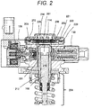
- FIG. 2 is a cross-sectional view of a high-pressure fuel pump main body in the present example. In FIG. 2 , the same reference signs are used for constituent parts equivalent to those in FIG. 1 .
- a portion 101 surrounded by a broken line shows the high-pressure fuel supply pump main body, and the mechanisms and parts shown surrounded by this broken line are integrated in a high-pressure fuel supply pump main body 101.
- Fuel is fed from a fuel tank 110 into the high-pressure fuel supply pump main body 101 through a feed pump 111, and the pressurized fuel is fed from the high-pressure fuel supply pump main body 101 to a fuel injector 122 through a common rail 121.
- An engine control unit 123 takes in the pressure of the fuel from a pressure sensor 124 and controls the feed pump 111, an electromagnetic coil 102 (solenoid) in the high-pressure fuel supply pump main body 101, and the fuel injector 122 to optimize the pressure.
- the fuel in the fuel tank 110 is pumped up by the feed pump 111 based on a control signal S1 from the engine control unit 123, is pressurized to an appropriate feed pressure, and is fed to a low-pressure fuel suction port (suction joint) 103 of the high-pressure fuel supply pump 101 through a suction pipe 112.
- the fuel having passed through the low-pressure fuel suction port 103 reaches a suction port 107 of the flow-rate control valve 106 constituting a capacity varying mechanism through a pressure pulsation reducing mechanism 104 and a suction passage 105.
- the pressure pulsation reducing mechanism 104 communicates with an annular low-pressure fuel chamber 109, which varies the pressure in conjunction with a plunger 108 performing a reciprocating motion by a cam mechanism (not shown) of the engine, and thereby reduces the pulsation of the pressure of the fuel to be sucked into the suction port 107 of the flow-rate control valve 106.
- the fuel flowing into the suction port 107 of the flow-rate control valve 106 passes through a suction valve 113 and flows into a pressurizing chamber 114.
- the valve position of the suction valve 113 is determined by controlling an electromagnetic coil 106 in the high-pressure fuel supply pump main body 101 based on a control signal S2 from the engine control unit 123.
- the cam mechanism (not shown) of the engine applies power for reciprocating to the plunger 108.
- the fuel is sucked from the suction valve 113 during a lowering process of the plunger 108, and the sucked fuel is pressurized during a rising process of the plunger 108, and is pressure-fed through a discharge valve mechanism 115 to the common rail 121 equipped with the pressure sensor 124. Thereafter, the fuel is injected by the fuel injector 122 to the engine based on a control signal S3 from the engine control unit 123.
- the discharge valve mechanism 115 provided at the outlet of the pressurizing chamber 114 includes a discharge valve seat 115a, a discharge valve 115b which comes into contact with and separates from the discharge valve seat 115a, a discharge valve spring 115c which biases the discharge valve 115b toward the discharge valve seat 115a, and the like.
- the discharge valve 115b is opened and the pressurized fuel is pressure-fed and supplied from the pressurizing chamber 114 toward the discharge passage 116.
- the parts constituting the flow-rate control valve 106 in FIG. 1 are a suction valve 113, a rod 117 for controlling the position of the suction valve 113, a movable portion 442, an anchor sliding portion 441 fixed to the anchor portion 118 and sliding with the rod 117, a suction valve spring 119, a biasing spring 125 biasing the rod toward the suction valve 113, and an anchor portion biasing spring 126.
- the suction valve 113 is biased in the valve closing direction by the suction valve spring 119 and biased in the valve opening direction via the rod 117 by the rod biasing spring 125.
- the movable portion 442 is biased in the valve closing direction by the anchor portion biasing spring 126.
- the valve position of the suction valve 113 is controlled by driving the rod 117 by the solenoid 102.
- the portion integrally constituted by the movable portion 442 and the anchor sliding portion 441 is referred to as the anchor portion 118.
- the solenoid 102 in the high-pressure fuel supply pump main body 101 is controlled by the control signal S2 transmitted from the engine control unit 123 to the flow-rate control valve 106, and the high-pressure fuel supply pump 101 thereby discharges the fuel flow rate so that the fuel to be pressure-fed through the discharge valve mechanism 115 to the common rail 121 is to be desired supply fuel.
- a relief valve 130 connects the pressurizing chamber 114 with the common rail 121.
- the relief valve 130 is a valve mechanism arranged in parallel with the discharge valve mechanism 115.
- the relief valve 130 forms a high-pressure flow passage 131 connecting the discharge passage 116 on the downstream side of the discharge valve 115b in the high-pressure fuel supply pump main body 101 with the pressurizing chamber 114, and bypasses the discharge valve 115b to the flow passage.
- the high-pressure flow passage 131 is provided with a relief valve 132 for restricting the flow of the fuel to one direction from the discharge flow passage 131 to the pressurizing chamber 114.
- the relief valve 132 is pressed against a relief valve seat 134 by a relief spring 133 which generates a pressing force, and is set to be opened when the pressure difference between the inside of the pressurizing chamber 114 and the inside of the high-pressure flow passage 131 exceeds a predetermined pressure determined by the relief spring 133 and the relief valve 130 separates from the relief valve seat 134.
- FIG. 2 is a diagram showing a specific example of the high-pressure fuel supply pump main body 101 mechanically integrally configured.
- the plunger 108 performing a reciprocating motion in the height direction (in this case, a vertical motion) at the center of drawing by the cam mechanism (not shown) of the engine is arranged in the cylinder 201, and the pressurizing chamber 114 is formed in the cylinder 201 above the plunger 108.
- the mechanism on the flow control valve 106 side is arranged at the left side of the center of the drawing, and the mechanism of a relief 130 is arranged at the right side of the center of the drawing.
- a low-pressure fuel suction port (not shown), a pressure pulsation reducing mechanism 202, a suction passage 203, and the like are arranged as a mechanism on the fuel suction side.
- a plunger internal combustion engine side mechanism 204 is shown.
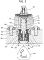
- the plunger internal combustion engine side mechanism 204 is embedded and fixed in the internal combustion engine main body as shown in FIG. 3 , and is referred to as an installation root portion accordingly.
- the low-pressure fuel suction port is not shown.
- the low-pressure fuel suction port can be shown in the cross-section from another angle, but is not directly related to the present invention, and the explanation and illustration thereof are omitted.
- FIG. 3 shows the installation root portion (plunger internal combustion engine side mechanism) 204 being embedded and fixed in the internal combustion engine main body. However, in FIG. 3 , the installation root portion 204 is shown at the center, and the illustration of other parts is omitted. In FIG. 3 , the low-pressure fuel suction port 301 is positioned at the upper portion of the fuel pump main body, but a low-pressure fuel suction port 131 may be provided at the circumference having the cylinder 108 as the axis.
- FIG. 3 a thick portion of a cylinder head 302 of the internal combustion engine is shown.
- an installation root portion installing hole 303 having two-stage diameters according to the shape of the installation root portion 204 is formed.
- the high-pressure fuel supply pump is tightly in contact with the flat face of the cylinder head 302 using a flange 304 provided at a pump main body 1, and is fixed by at least two or more bolts 305.
- the installation flange 304 is welded to the pump main body 1 at a welded portion 306 around its entire circumference by a laser, and an annular fixing portion is thereby formed.
- an O-ring 307 is fitted on the pump main body 1, and which prevents the engine oil from leaking to the outside.
- the flange 304 and the pump main body 1 may be integrally formed.
- a plunger root portion 204 is provided with a tappet 310 which converts the rotational motion of a cam 309 attached to the camshaft of the internal combustion engine into a vertical motion at a lower end 308 of the plunger 108 and propagates it to the plunger 108.
- the plunger 108 is pressed against the tappet 310 by a spring 312 via a retainer 311. The plunger 108 thereby reciprocates vertically in accordance with the rotational motion of the cam 309.
- a plunger seal 314 held at the lower end portion of the inner circumference of a seal holder 313 is installed in a state of slidably contacting with the outer circumference of the plunger 108 at the lower portion of a cylinder 315 in the drawing, and the fuel in an annular low-pressure fuel chamber 316 can be sealed when the plunger 108 slides to prevent the fuel from leaking to the outside.
- the cylinder 201 guiding the reciprocating motion of the plunger 108 and having a bottomed cylindrical end portion (at the upper side in FIG. 2 ) to form the pressurizing chamber 114 inside is attached to the high-pressure fuel supply pump main body 101. Furthermore, in order to communicate with the flow-rate control valve 106 connecting to the pressurizing chamber 114 and with the discharge valve mechanism 115 for discharging the fuel from the pressurizing chamber 114 to the discharge passage, an annular groove 206 and a plurality of communicating holes connecting an annular groove 207 with the pressurizing chamber 114 are provided on the outer circumference side.
- the cylinder 201 is fixed at its outer diameter by being press-fit and joined to the high-pressure fuel supply pump main body 101, and sealed on the press-fit cylindrical face so that the pressurized fuel does not leak to the low-pressure side from the gap between the high-pressure fuel supply pump main body 101 and the cylinder 201.
- the cylinder 201 has a small diameter portion 207 at the outer diameter on the pressurizing chamber 114 side. By pressurizing the fuel in the pressurizing chamber 114, the force acts on the cylinder 201 toward a low-pressure fuel chamber 220. However, by providing a small diameter portion 230 in the pump main body 101, the cylinder 201 is prevented from coming out to the low-pressure fuel chamber 208 side.
- the faces are brought in contact with each other in the axial direction, which functions as a double seal in addition to the seal of the high-pressure fuel supply pump main body 101 and the cylinder 201 on the contact cylindrical face.
- a damper cover 208 is fixed to the head portion of the high-pressure fuel supply pump main body 101.
- a suction joint (not shown) is provided on the low-pressure fuel chamber side of the high-pressure fuel supply pump main body 101, and a low-pressure fuel suction port (not shown) is formed.
- the fuel having passed through the low-pressure fuel suction port passes through a filter (not shown) fixed inside the suction joint and reaches a suction port 209 of the flow-rate control valve 106 through the pressure pulsation reducing mechanism 202 and the low-pressure fuel flow passage 203.
- the plunger 108 has a large diameter portion 210 and a small diameter portion 211, and the volume of the annular low-pressure fuel chamber 212 is increased or decreased by the reciprocating motion of the plunger 108. Since a fuel passage 320 ( FIG. 3 ) communicates with the low-pressure fuel chamber 220, the increase or decrease of the volume causes the fuel to flow from the annular low-pressure fuel chamber 212 to the low-pressure fuel chamber 220 when the plunger 108 descends, and to flow from the low-pressure fuel chamber 220 to the annular low-pressure fuel chamber 212 when the plunger 108 rises. As a result, it is possible to reduce the flow rate of the fuel to the inside and outside of the pump in a suction process or a return process of the pump, and to reduce pulsation.
- the low-pressure fuel chamber 220 is provided with the pressure pulsation reducing mechanism 202 which suppresses the spread of the pressure pulsation generated in the high-pressure fuel supply pump to a fuel pipe 130 ( FIG. 1 ).
- the fuel flowing into the pressurizing chamber 114 is returned to a suction passage 1203 (the suction port 209) through the suction valve 113 in the valve opening state for the capacity control, the fuel returned to the suction passage 203 (the suction port 209) generates pressure pulsation in the low-pressure fuel chamber 220.
- the pressure pulsation reducing mechanism 202 is formed by a metal damper in which two corrugated disk-shaped metal plates are bonded together at the outer circumferences thereof and an inert gas such as argon is injected into the inside, and pressure pulsation is absorbed and reduced by expansion and contraction of the metal damper.
- An installation bracket 221 fixes the metal damper to the high-pressure fuel supply pump main body 101.
- the discharge valve mechanism includes the discharge valve seat 115a, the discharge valve 115b which comes into contact with and separates from the discharge valve seat 115a, the discharge valve spring 115c which biases the discharge valve 115b toward the discharge valve seat 115a, and a discharge valve holder 115d housing the discharge valve 115b and the discharge valve seat 115a.
- the discharge valve seat 115a and the discharge valve holder 115d are joined by welding at a contact portion (not shown) to integrally form the discharge valve mechanism 115.
- the discharge valve 8b when there is no fuel pressure difference between the pressurizing chamber 114 and a fuel discharge port 12, the discharge valve 8b is pressed against the discharge valve seat 115a by the biasing force of the discharge valve spring 8c and is in a valve closing state.
- the discharge valve 115b is opened against the discharge valve spring 115c only when the fuel pressure in the pressurizing chamber 114 becomes larger than the fuel pressure at the fuel discharge port, and the fuel in the pressurizing chamber 114 is discharged to the common rail 121 through the fuel discharge port 12 at a high pressure.
- the discharge valve 115b When the discharge valve 115b is opened, it contacts with a discharge valve stopper, and the stroke is restricted.
- the stroke of the discharge valve 115b is about determined by the discharge valve stopper.
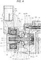
- FIG. 4 shows the state in a suction process in suction, return, and discharge processes in the pump operation
- FIGS. 5 and 6 show the state in the discharge process.
- the structure on the flow-rate control valve 106 side will be described with reference to FIG. 4 .
- the structure on the flow-rate control valve 106 side is roughly divided into a suction valve portion 4A constituted mainly by the suction valve 113, and a solenoid mechanism portion 4B constituted mainly by the rod 117, the movable portion, and the solenoid 102.
- the suction valve portion A includes the suction valve 113, a suction valve seat 401, a suction valve stopper 402, the suction valve biasing spring 119, and a suction valve holder 403.
- the suction valve seat 401 is cylindrical and has a seat portion 405 on the inner circumference side in the axial direction and two or more suction passage portions 404 radially around the axis of the cylinder, and is held by being press-fit and joined to the high-pressure fuel supply pump main body 101 at the outer circumferential cylindrical face.
- the suction valve holder 403 has radial claws in two or more directions, and the outer circumferential side of the claw is coaxially fitted and held on the inner circumferential side of the suction valve seat 401.
- a suction stopper 402 having a cylindrical shape and a flange shape at one end portion is held by being press-fit and joined to the inner circumferential cylindrical face of the suction valve holder 403.
- the suction valve biasing spring 119 is arranged at a small diameter portion for coaxially stabilizing one end of the spring and on the inner circumferential side of the suction valve stopper 402.
- the suction valve 113 is fitted between a suction valve seat portion 405 and the suction valve stopper 402 so as to fit the suction valve biasing spring 119 on a valve guide portion 444.
- the suction valve biasing spring 119 is a compression coil spring and is installed so that a biasing force acts in a direction in which the suction valve 113 is pressed against the suction valve seat portion 405.
- the suction valve biasing spring 119 is not limited to a compression coil spring, and may be of any form as long as it can provide a biasing force, or may be a plate spring having a biasing force integrated with the suction valve 113.
- the suction valve portion A By providing the suction valve portion A in this manner, in the suction process of the pump, the fuel having passed through the suction passage 404 and flowing into the flow-rate control valve passes between the suction valve 113 and the seat portion 405, passes between the outer circumferential side of the suction valve 113 and a fuel passage 445 provided at the outer diameter of the suction valve stopper 402, passes through the high-pressure fuel supply pump main body 101 and the passage of the cylinder, and flows into the pressurizing chamber. In the discharge process of the pump, the suction valve 113 comes into contact with the suction valve seat portion 405 and thereby seals the fuel, and which functions as a check valve preventing the fuel from flowing backward to the inlet side.
- the movement amount 446 of the suction valve 113 in the axial direction is finitely regulated by the suction valve stopper 402. This is because that performance of the pump is deteriorated by the increase in the back-flow amount due to the response delay when the suction valve 113 is closed if the movement amount is too large.
- the regulation of the movement amount can be defined by the axial dimensions and the press-fitting positions of the suction valve seat 401, the suction valve 113, and the suction valve stopper 402.
- the suction valve stopper 402 is provided with an annular protrusion to reduce the contact area with the suction valve stopper 402 while the suction valve 113 is being opened. This is because that the suction valve 113 easily separates from the suction valve stopper 402 when the valve opening state is shifted to the valve closing state, that is, the valve closing responsiveness is to be improved.
- the annular projection is not provided, that is, when the contact area is large, the pressure between the suction valve 113 and the suction valve stopper 402 decreases when the suction valve 113 separates from the suction valve stopper 402, the squeezing force acts in a direction in which the movement of the suction valve 113 is hindered, and the suction valve 113 is difficult to separate from the suction valve stopper 402.
- suction valve 113 Since the suction valve 113, the suction valve seat 401, and the suction valve stopper 402 repeatedly collide with each other during their operations, it is preferable to use a material which is martensitic stainless steel having high strength, high hardness and excellent corrosion resistance, and subjected to heat treatment. It is preferable to use an austenitic stainless steel material for the suction valve spring 119 and the suction valve holder 403 in consideration of corrosion resistance.
- the solenoid mechanism portion B includes the rod 117 as a movable portion, a guide portion 410 as a movable portion and a fixed portion, an outer core 411, a fixed core 412, the rod biasing spring 125, the anchor portion biasing spring 126, a cover portion 415, a yoke 423, and the solenoid 102.
- the rod 117 which is a movable portion and the anchor 118 are formed separately.
- the rod 117 is held slidably in the axial direction on the inner circumferential side of the guide portion 410, and the inner circumferential side of the anchor sliding portion 441 of the movable portion is held slidably on the outer circumferential side of the rod 117. That is, both of the rod 117 and the anchor portion 118 are formed to be slidable in the axial direction within a range geometrically regulated.
- the anchor sliding portion 441 is formed to contact with a flange portion 417a of the rod 117 at the end face on the fixed core 412 side.
- the anchor portion 118 has one or more through holes 450 penetrating through the anchor sliding portion 441 in the axial direction of the component, and the restriction of movement by the pressure difference across the anchor portion 118 is thereby excluded as much as possible.
- the through hole 450 may be provided at the center of the rod 117 so as to connect the space on the fixed core 412 side of the anchor portion 118 with the space 413 on the upstream side of the suction valve seat 401 by providing a lateral groove fuel passage on the suction valve 113 side rather than the guide portion 410 so as to be substantially parallel to the suction passage portion 404 .
- the space on the fixed core 412 side of the anchor portion 118 can communicate without providing the fuel passage 414 of the guide portion 410, and the machining cost of the guide portion 410 can be suppressed.
- the guide portion 410 is arranged by being inserted into the inner circumferential side of the hole into which the suction valve 113 of the high-pressure fuel supply pump main body 101 is inserted in the radial direction, abutting against one end portion of the suction valve seat 405 in the axial direction, and being sandwiched between the outer core 411 welded and fixed to the high-pressure fuel supply pump main body 101 and the high-pressure fuel supply pump main body 101.
- the fuel passage 414 penetrating in the axial direction is provided also at the guide portion 410 so that the pressure in the fuel chamber on the anchor portion 118 side does not hinder the movement of the anchor portion 118 in order for the anchor portion 118 to freely smoothly move.
- the outer core 411 has a thin-walled cylindrical shape on the side opposite to the portion to be welded to the high-pressure fuel supply pump main body 101, and the fixed core 412 is inserted into the inner circumferential side and fixed by being welded and joined.
- a rod biasing spring 40 is arranged on the inner circumferential side of the fixed core 412 using the small diameter portion as a guide so that the rod 117 comes into contact with the suction valve 113, and applies a biasing force in the direction in which the suction valve 113 separates from the suction valve seat 401, that is, in the valve opening direction of the suction valve 113.
- the anchor portion biasing spring 126 is arranged so as to apply a biasing force to the anchor portion 118 toward a rod flange portion 117a while maintaining the same axis by inserting one end into a central bearing portion 452 having a cylindrical diameter provided on the center side of the guide portion 410.
- the movement amount 470 of the anchor portion 118 is set to be larger than the movement amount 446 of the suction valve 113.
- the excluded volume associated with the movement of the anchor portion 118 at the time of the valve closing flows between the anchor portion 118 and the fixed core 812, whereby the pressure between the anchor portion 118 and the fixed core 812 increases.
- a fluid force that is, a squeezing force acts on the anchor portion 118 and pushes it in the direction opposite to the valve closing direction. Since the squeezing force is generally proportional to the cube of the gap between the anchor portion 118 and the fixed core 812, the influence is larger as the gap is smaller.
- the suction valve 113 By increasing the movement amount of the anchor portion 118 more than the movement amount 447 of the suction valve 113, the suction valve 113 is closed before the squeezing force acting on the anchor portion increases, and the decrease in the discharge flow rate caused by the deterioration of responsiveness of the suction valve 113 can be suppressed.
- a martensitic stainless steel subjected to heat treatment is used in consideration of hardness and corrosion resistance. It is preferable that ferrite magnetic stainless steel is used for the anchor portion 118 and the fixed core 412 to form a magnetic circuit, and that austenitic stainless steel is used for the rod biasing spring 125 and the anchor portion biasing spring 126 in consideration of corrosion resistance.
- three springs are arranged in an organic manner in the suction valve portion A and the solenoid mechanism portion B.
- the suction valve biasing spring 119 arranged in the suction valve portion A, and the rod biasing spring 125 and the anchor portion biasing spring 126 arranged in the solenoid mechanism portion B correspond to the three springs.
- all the springs are coil springs, but any type can be used as long as it can obtain the biasing force.
- each spring force acts on the rod 117 as a force f1 in a direction in which the suction valve 113 is separated from the suction valve seat portion 405, that is, in a direction in which the valve is opened.
- the force f1 in the direction in which the valve is opened is expressed by the following expression (2).
- f1 force of the rod biasing spring 125 ⁇ ( force of the anchor portion biasing spring 126 + force of the suction valve biasing spring 119 + force for the suction valve to close due to fluid )
- the solenoid portion includes the cover portion 415, the yoke 423, the solenoid 102, a bobbin 453, a terminal 454, and a connector 455.
- the solenoid 102 in which a copper wire is wound a plurality of times on the bobbin 453 is arranged so as to be surrounded by the cover portion 415 and the yoke 423, and is molded and fixed integrally with the connector which is a resin member.
- One ends of the two terminals 454 are connected to both ends of the copper wire of the solenoid 102 so as to be energizable.
- the terminal 454 is integrally molded with the connector 455, and the other end is connectable to the engine control unit side.
- a seal ring 418 is provided on the radial solenoid 102 side in the diameter direction of the outer diameter of the fixed core 412.
- the seal ring 418 is fixed by being press-fitted and joined to the outer diameter portion 417 of the fixed core 412 and the outer diameter portion 420 of the outer core 411, and seals the fuel by welding the vicinity of the press-fitting fixed portion.
- the seal ring 418 is provided on the outer diameter side opposed to a suction face 421 of the fixed core 412 in the radial direction.
- a small diameter portion 440 of the yoke 423 is press-fitted and fixed to the outer core 411. At that time, the inner diameter side of the cover portion 415 comes into contact with a fixed core 39 or comes close to it with a slight clearance.
- Both of the cover portion 415 and the yoke 423 are made of a magnetic stainless steel material to form a magnetic circuit and in consideration of corrosion resistance, and the bobbin 453 and the connector 454 are made of a high strength heat resistant resin in consideration of a strength property and heat resistance property.
- the solenoid 102 is made of copper, and the terminal 454 is made of metal plated brass.
- the magnetic circuit is formed by the anchor portion 118, the fixed core 412, the cover portion 415, the yoke 423, and the outer core 411, and when current is supplied to the solenoid 102, a magnetic attraction force is generated between the fixed core 412 and the anchor portion 118, whereby a force pulling the anchor portion 118 toward the fixed core 412 is generated.
- austenitic stainless steel for the seal ring 418, the magnetic flux easily passes between the fixed core 412 and the anchor portion 118, and the magnetic attraction force can be improved.
- the magnetic flux flowing on the outer core 411 side can be reduced by making the portion positioned at the outer diameter in the radial direction of the suction face 421 thinner as much as possible. As a result, the magnetic flux passing between the fixed core 412 and the anchor portion 118 increases, and the magnetic attraction force can be improved.
- the anchor portion 118 which is the movable portion, is attracted to the fixed core together with the rod 117, and the anchor portion continues to move until the anchor portion 118 comes into contact with the fixed core 412.
- the pump in the suction, return, and discharge processes in the pump operation, the pump operates as follows.
- the suction process will be described.
- the plunger 108 moves toward the cam 309 (the plunger 108 descends) by the rotation of the cam 309 in FIG. 3 . That is, the position of the plunger 108 moves from the top dead center to the bottom dead center.
- the suction process state referring to, for example, FIGS. 1 , 2 and 3 , the volume of the pressurizing chamber 114 increases and the fuel pressure in the pressurizing chamber 114 decreases.
- the return process will be described.
- the plunger 108 moves in the rising direction by the rotation of the cam 309 in FIG. 3 . That is, the position of the plunger 108 starts to move from the bottom dead center to the top dead center.
- the volume of the pressurizing chamber 114 decreases associated with the compression motion after the suction in the plunger 108.
- the fuel sucked into the pressurizing chamber 114 once is returned to suction passage 404 through the suction valve 113 in the valve opening state again, and the pressure in the pressurizing chamber 114 does not increase. This process is referred to as the return process.
- FIG. 5 shows the positional relation of the parts on the flow-rate control valve 106 side when the magnetic attraction force is acting, the description will be made with reference to FIG. 5 .
- the magnetic flux passes between the fixed core 412 and the anchor portion 118, and the magnetic attraction force is generated in the anchor portion 118, whereby the magnetic attraction which attracts the anchor portion 118 toward the fixed core 412 is generated.
- the rod 117 separates from the suction valve 113 by the locking mechanism of the anchor portion 118 and the rod flange portion 417a.
- the suction valve 113 is closed by the biasing force of the suction valve biasing spring 119 and the fluid force caused by the fuel flowing into the suction passage 404.
- the fuel pressure in the pressurizing chamber 114 rises together with the rising motion of the plunger 108.
- the fuel pressure in the pressurizing chamber 114 exceeds the pressure of the fuel discharge port of the discharge valve mechanism 115, the fuel is discharged at a high pressure through the discharge valve mechanism 115, and is supplied to the common rail 121. This process is referred to as the discharge process.
- the compression process (rising process from the lower starting point to the upper starting point) of the plunger 108 includes the return process and the discharge process.
- the amount of high-pressure fuel to be discharged can be controlled. If the timing to energize the solenoid 102 is advanced, the ratio of the return process in the compression process is small, and the ratio of the discharge process is large. That is, the amount of the fuel returned to the suction passage 404 is small, and the amount of the fuel discharged at a high pressure is increased. On the other hand, if the energization timing is delayed, the ratio of the return process in the compression process is large, and the ratio of the discharge process is small.
- the energization timing to the solenoid 102 is controlled by a command from the engine control unit 123, whereby the amount of fuel discharged at a high pressure can be controlled to an amount required by the internal combustion engine.
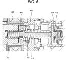
- FIG. 6 shows the positional relation of the parts on the flow-rate control valve 106 side in the discharge process. This shows a state of a non-energized state in which the solenoid 102 is not energized when the suction valve 113 is being closed (in a closing state) after the pressure in the pump chamber has sufficiently increased. This state prepares, for the next cycle process, to effectively generate the next magnetic attraction force and to provide the effect.
- This structure has a feature in performing the preparation.
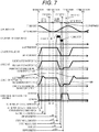
- the timing chart of FIG. 7 shows in the order from the top: a) position of the plunger 108; b) current of the solenoid 102; c) position of the suction valve 113; d) position of the anchor rod 117; e) position of the anchor portion 118; and f) pressure in the pressurizing chamber 114.
- the abscissa shows each time t in one cycle period from the suction process, through the return process and the discharge process and to the suction process in time series.
- the suction process is a period in which the position of the plunger 108 reaches the bottom dead center from the top dead center
- the return process and the discharge process are the periods in which the position of the plunger 108 reaches the top dead center from the bottom dead center.
- the coil current an attraction current is applied the solenoid 102 during the return process, and the process is shifted to the discharge process while a holding current is being applied.
- C) the position of the suction valve 113, d) the position of the rod 117, and e) the position of the anchor portion 118 are changed according to the generation of the magnetic attraction force by the current supply to b) the solenoid 102, and are returned to the original positions at the beginning of the suction process .
- the suction valve 113 collides with the suction valve stopper 402, and the suction valve 113 stops at that position. Similarly, the rod 117 also stops at the position where the tip contacts the suction valve 113 (the valve opening position of the plunger rod in FIG. 7 ).
- the anchor portion 118 moves initially in the valve opening direction of the suction valve 113 at the same speed as the rod 117, but is continuing to move by the inertial force after the time t2 when the rod 117 comes into contact with the suction valve 113 and stops.
- the portion indicated by OA in FIG. 7 is the region of this overshoot.
- the anchor portion biasing spring 126 overcomes the inertial force, the anchor portion 118 moves again in the direction approaching the fixed core 412, and stops at the position where the anchor portion 118 comes into contact with the rod flange portion 417a in a state of being pressed (anchor portion valve opening position in FIG. 7 ).
- the time t3 indicates the stop time of the anchor portion 118 due to the re-contact of the rod 117 and the anchor portion 118.
- FIG. 4 shows the respective positions of the anchor portion 118, the rod 117, and the suction valve 113 at the time t4 in the stable state after the stop time t3.
- the rod 117 completely separates from the anchor portion 118 in the portion indicated by OA, but the rod 117 and the anchor portion 118 may remain in contact with each other.
- the load acting on the contact portion of the rod flange portion 417a and the anchor portion 118 decreases after the anchor rod 117 stops moving, and when it becomes 0, the anchor portion 118 starts to separate from the anchor rod 117.
- the force of the anchor portion biasing spring 126 may be set not to be 0 but to leave a slight load.
- the magnitude of the abnormal noise depends on the magnitude of energy at the time of collision
- the energy colliding with a suction valve stopper 32 is generated only by the mass of the suction valve 113 and the mass of the anchor rod 117 since the rod 117 and the anchor 118 are formed separately in the present invention. That is, since the mass of the anchor portion 118 does not contribute to the collision energy, by forming the rod 117 and the anchor portion 118 separately, the problem of abnormal noise can be reduced.
- the anchor portion biasing spring 126 is not provided although the rod 117 and the anchor portion 118 are formed separately, the anchor portion 118 continues to move in the valve opening direction of the suction valve 113 due to the inertial force, and collides with the end face on the fixed core 412 side of a guide portion 117, and which can cause a problem that abnormal noise occurs at a portion different from the collision portion.
- the collision causes abrasion, deformation, and the like of the sliding portion 441 and a guide portion 442 which are components of the anchor portion 118.
- the abrasion generates metal foreign substances, and the foreign substances are caught in the sliding portion or the seat portion, and deform and impairs the bearing function, whereby the function of the suction valve solenoid mechanism can be impaired.
- the sliding portion 441 which requires strength to collide with and slide on the movable portion 442 constituting the magnetic circuit separately, impairing the function of the suction valve solenoid mechanism can be suppressed.
- ferrite stainless steel having a good magnetic property is used for the movable portion 442, and that austenitic stainless steel having high hardness is used for the sliding portion 441.
- the anchor portion biasing spring 126 is not provided, in order for the anchor portion 118 to continue to move in the valve opening direction by the inertial force, the distance from the face opposed to the fixed core 412 of the anchor portion 118 to the suction face 421 of the fixed core 412 is to be large (the OA portion in FIG. 7 ) .
- the magnetic resistance between the fixed core 421 and the anchor portion 118 increases, and the required magnetic attraction force cannot be obtained.
- the required magnetic attraction force cannot be obtained, the maximum flow rate of the fuel discharged from the high-pressure fuel supply pump can decrease.
- the anchor portion biasing spring 126 has an important function for preventing the decrease in the flow rate.
- the plunger 108 After the suction valve 113 is opened, the plunger 108 further descends to reach the bottom dead center (time t5). During this time, the fuel continues to flow into the pressurizing chamber 114, and this process is the suction process. The plunger 108 descending to the bottom dead center is in the rising process and the process is shifted to the return process.
- the suction valve 113 remains stopped in the valve opening state by the force f1 in the direction in which the valve is opened, and the direction of the fluid passing through the suction valve 113 is in the exact opposite direction. That is, whereas the fuel has flowed into the pressurizing chamber 114 from the passage of the suction valve seat 405 in the suction process, the fuel returns from the pressurizing chamber 114 toward the passage of the suction valve seat 405 at the timing of the rising process. This process is the return process.
- ethanol mixed gasoline represented by biofuel has spread. Since ethanol mixed gasoline has lower energy density than gasoline which does not contain ethanol, the amount of fuel required to be injected by an injector 122 increases to obtain the same output.
- the valve closing force due to the fluid acting on the suction valve 113 increases as the flow speed of the fuel flowing through the suction valve seat 405 becomes high, and the valve closing force increases as the fuel injected by the injector 122 increases.
- the time t7 is the closing motion start time of the suction valve 113
- the time t8 is the hold current start time
- the time t9 is the valve closing time of the suction valve 113
- the time t10 is the energization end time of the solenoid 102.
- the anchor portion 118 moves in the valve closing direction, and the rod 117 in contact with it at the flange portion 417a in the axial direction similarly moves in the valve closing direction. Then, the suction valve 113 starts to be closed (time t9) by the force of the suction valve biasing spring 126 and by the decrease in the fluid force, mainly in the static pressure due to the flow speed passing through the seat portion from the pressurizing chamber side.
- the anchor portion biasing spring 126 is provided.
- the anchor portion 118 cannot move to the fixed core 412 at a desired timing, the discharge process cannot be started because the suction valve 113 is kept opened at a desired discharge timing. That is, since a required discharge amount cannot be obtained, the desired engine combustion cannot be performed.
- the anchor portion biasing spring 126 has an important function to prevent the abnormal noise problem that can occur in the suction process, and to prevent the problem that the discharge process cannot be started.
- the anchor rod 117 separates from the suction valve 113, and e) the anchor portion 118 thereby moves toward the fixed core 412, collides with the fixed core 412, and stops.
- a rod 35 continues to move due to the inertial force after the anchor portion 36 stops, but is pushed back when the rod biasing spring 126 overcomes the inertial force, and returned to the position where the flange portion 417a comes into contact with the anchor portion 118.
- the magnitude of the abnormal noise depends on the magnitude of the energy at the time of collision, but the anchor rod 117 and the anchor portion 118 are formed separately, and only the mass of the anchor portion 118 contributes to the energy colliding with the fixed core 412. That is, since the mass of the rod 117 does not contribute to the collision energy, by forming the rod 117 and the anchor portion 118 separately, the problem of abnormal noise is reduced.
- cavitation occurs due to a rapid decrease in the static pressure, and cavitation erosion can occur at the seal ring 418.
- a thin wall portion is not required to be formed in the outer core 411 in order to propose leakage magnetic flux passing through a portion other than the suction face 421, and the cavitation can be suppressed.
- one or more through holes 450 in the axial direction are provided on the center side of the sliding portion 441 constituting the anchor portion 118.
- the anchor portion 36 and the rod 35 are integrally formed, a phenomenon that raises a further concern of the above problem occurs.
- the engine rotates at a high speed, that is, when the rising speed of the plunger 108 is high, the force closing the suction valve 113 by the fluid having a very high speed is added to the force that the anchor portion 118 moves to the fixed core 412 caused when current is supplied to the solenoid 102, and the force is increased.
- the anchor rod 117 and the anchor portion 118 rapidly come close to the fixed core 412, and the speed at which the fluid in that space is pushed out further increases, whereby the problem of erosion becomes larger. If the capacity of the through hole 450 of the anchor portion 118 is insufficient, the problem of erosion cannot be solved.
- the through hole 450 is provided in the end face on the fixed core 412 side of the movable portion 442, the attractive area is reduced, and the magnetic attraction force is lowered.
- the through hole 450 can be provided at a position in the downstream of the movable portion 442 which is not the main passage of the magnetic circuit, and both of the magnetic attraction force and the fuel passage can be secured.
- the position of the through hole 450 in the radial direction is preferably on the outer diameter side rather than the inner diameter of the fixed core 412 or the inner diameter of the end face on the fixed core 412 side of the movable portion 442.
- the anchor portion 118 and the rod 117 are formed separately, the rod 117 is only pushed out toward the fixed core 412 when the force closing the suction valve 113 is applied to the rod 117, and the anchor portion 118 is left behind but moves toward the fixed core 412 only by the normal magnetic attraction force. That is, a rapid reduction in space does not occur, and the problem of erosion can be prevented.
- the rod 117 and the anchor portion 118 move simultaneously at the timing when the magnetic attraction force acting on the anchor portion 118 becomes lower than the force in the valve opening direction acting on the anchor portion 118 and the rod 117.
- the anchor portion 118 continues to move toward the suction valve 113 (the state of OB in FIG. 7 ) due to the inertial force after the rod 117 stops in a state in which the tip of the rod 117 is in contact with the closing suction valve 113.
- the anchor portion biasing spring 126 overcomes the inertial force and applies the biasing force to the anchor portion 118 toward the fixed core 412, the anchor portion 118 can stop in contact with the flange portion 417a of the rod 117 (state of FIG. 6 ).
- the anchor portion biasing spring 126 If the anchor portion biasing spring 126 is not provided, the anchor portion 118 moves toward the suction valve 113 without stopping similarly to the above-described suction process, and the problems of abnormal noise caused by the collision with the guide portion 410 and function failure can occur. However, since the anchor portion biasing spring 41 is provided, the above problems can be prevented.
- a high-pressure fuel supply pump suitable for pressurizing the required amount of the fuel guided to the low-pressure fuel suction port (not shown) to a high pressure by the reciprocating motion of the plunger 108 in the pressurizing chamber 114 of the high-pressure fuel supply pump main body 101 as the pump main body, and for pressure-feeding the fuel from the fuel discharge port (not shown) to the common rail 121.
- the suction valve 113 Since the suction valve 113 is required to be closed quickly, it is preferable to set the spring force of the suction valve spring 119 as large as possible and to set the spring force of the anchor portion biasing spring 41 to be small. As a result, it is possible to prevent deterioration of the flow efficiency due to closing delay of the suction valve 113.
- the anchor portion 118 when the anchor portion 118 and the rod 117 are formed separately and the anchor portion biasing spring 126 is provided, the anchor portion 118 overshoots like OA and OB shown in FIG. 7 .
- the anchor portion 118 and the rod 117 repeat separation and contact, and which can cause abrasion.
- Preventing this abrasion is a new problem that arises because the anchor portion 118 and the rod 117 are formed separately and the anchor portion biasing spring 126 is provided.
- the anchor portion 118 is formed of the movable portion 442 forming a magnetic path and the sliding portion 441 sliding on the rod 117.
- the sliding portion 441 is subjected to surface treatment such as plating treatment, or heat treatment such as quenching treatment, to increase the hardness.
- surface treatment such as plating treatment, or heat treatment such as quenching treatment
- plating treatment treatment can be performed only to the sliding portion 441 by masking a portion unnecessary for the treatment.
- quenching treatment methods such as high-frequency quenching, laser quenching, or partial carburizing quenching in which a carburizing agent is applied to a portion where the treatment is unnecessary can be used.
- the functions of colliding and sliding with other members are integrated with the sliding portion 441 having increased hardness in this manner. As a result, it is possible to prevent abrasion caused by sliding and collision.
- the structure in the present example it is possible to provide a highly reliable electromagnetic valve without lowering the magnetic attraction force, and a low-noise high-pressure fuel supply pump equipped with the electromagnetic valve.
- the flow-rate control valve 106 is not limited to the high-pressure fuel pump main body 101, and an effect of improving responsiveness is obtained when the flow-rate control valve 106 is applied to an apparatus for controlling the flow rate such as an injector.
- the position of the passage 460 in the axial direction may be provided on the fixed core side rather than the suction passage 404.
- the passage 460 and the suction passage 404 are formed so that the cross sections of the fuel passages overlap each other.
- the sliding face of the guide portion 452 with the anchor rod 117 is extended to a position opposed to the passage 460 in the radial direction.
- the sliding length can be secured, and it is possible to secure the strength against the abrasion of the sliding portion due to the sliding, and to suppress the inclination of the anchor portion 118.
- the gap between the outer diameter of the anchor portion 118 and the inner diameter of the outer core 411 can be designed to be small, and it is possible to reduce the magnetic resistance and to improve the magnetic attraction force.
- FIG. 8 is an enlarged view of the flow-rate control valve 106 in the first embodiment.
- FIG. 8 the same reference signs are used for parts equivalent to those in FIGS. 1 and 4 .
- FIG. 9 is an enlarged view of a cover portion 815, a fixed core 812, and a yoke 423 which are components of a magnetic circuit indicated by the enlarged portion 834 in FIG. 8 .
- the magnetic flux lines generated in the magnetic circuit are shown by the dotted lines.
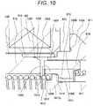
- FIG. 10 is an enlarged view of the enlarged portion 886 constituted by the cover portion 815, the fixed core 812, an anchor portion 818, and an outer core 811 in FIG. 8 .
- the fixed core 812 is provided with an enlarged portion 830 which is in contact with the cover portion 815 in the axial direction and has an outer diameter enlarging toward the outer circumferential side of a solenoid 102, and is provided with a small diameter portion 831 the outer diameter of which is reduced.
- the cover portion 815 has an inner circumferential side opposing face 835 opposed to, in the radial direction, the small diameter portion 831 which is an end face on the outer circumferential side of the fixed core 812.
- the movable portion 442 and the sliding portion 441 in first example are integrally formed in the first embodiment, and are referred to as the anchor portion 418.
- the fixed core 812 is provided with the small diameter portion 831 on the outer side in the axial direction, that is, on the side opposite to the anchor portion 118.
- a fixing pin 832 is fixed to the small diameter portion 831 to press the cover portion 815 so as to be in contact with the outer diameter enlarged portion 830, and the movement of the cover portion 815 in the axial direction is thereby restricted.
- a seal ring 818 is provided on a suction valve 113 side opposed to the enlarged portion 830 in the axial direction.
- the outer diameter of the enlarged portion 830 of the fixed core 812 is larger than the inner diameter of the seal ring 818.
- the seal ring 818 is press-fitted and fixed to an outer diameter portion 419 of the fixed core 412 and an outer diameter portion 420 of the outer core 411 to seal the fuel by, for example, being welded and joined.
- the seal ring 818 is provided at a position opposing a suction face 421 of the fixed core 412 and a movable core 118 in the radial direction to block the magnetic flow other than that between a movable core 117 and the fixed core 812 and to reduce the leakage magnetic flux.
- the magnetic flux flowing through the fixed core 812 and the movable core 118 increases, and the magnetic attraction force can be improved.
- the guide portion 452 and the suction valve seat 401 in the first example are integrally formed, and the member constituted by the guide portion 452 and the suction valve seat 401 is newly referred to as a guide portion 852.
- the magnetic gap between the cover portion 815 and the fixed core 812 is eliminated, and the magnetic resistance is reduced.
- the magnetic attraction force can increase, and the responsiveness of the anchor portion 418 is improved, whereby the responsiveness of the suction valve 813 is also improved.
- the magnetic flux which can be generated in the magnetic circuit increases as the magnetic resistance decreases, and the magnetic flux passing between the anchor portion 818 and the fixed core 812 also increases relatively.
- the magnetic permeability between the fixed core 812 and the cover portion 815 is to be the magnetic permeability of the magnetic material constituting the cover portion 815 and the fixed core 812 from the magnetic permeability of a vacuum.
- a gap 842 between the outer diameter of the cover portion 815 and the inner diameter of the yoke 423 is preferably to be smaller than a gap 840 between the inner diameter of the cover portion 815 and the small diameter portion 831 of the fixed core 812.
- the magnetic flux flowing from the fixed core 812 to the cover portion 815 hardly flows between the cover portion 815 and the small diameter portion 831, and easily flow to a contact face 833 of the fixed core 812 and the cover portion 815. Since the main path of the magnetic flux is between the cover portion 815 and the yoke 423, a large amount of magnetic flux generated in the magnetic circuit passes. Thus, by forming the magnetic gap between the cover portion 815 and the yoke 423 through which a large amount of magnetic flux passes to be small, the magnetic resistance can be reduced and the magnetic attraction force can be improved.
- the load at the time of press fitting acts on the seal ring 418, and the seal ring 418 and the welded portion of the seal ring 418 can be deformed by the load at the time of press fitting.
- the stress tends to act on the welded portion between the seal ring 418 and the fixed core 812, and the welded portion between the seal ring 418 and an inner core 811.
- the pressing force is generated by the fixing pin 833 so that the cover portion 815 is regulated in the axial direction only by the outer diameter enlarged portion 830 of the fixed core 812, a large load at the time of press fitting does not act on the seal ring 418 and its welded portion, and the magnetic attraction force generated by the deformation of the seal ring 418 or deformation due to the load and the change in the movement amount of the anchor portion 118 suppresses the variation.
- the fixed core 812 and the anchor portion 418 are used as compared with the cover portion 815, the yoke 423, and the outer core 811.
- the fixed core 812 and the anchor portion 418 which are enclosed on the inner diameter side closer to the axial direction than the cover portion 815, the yoke 423, and the outer core 811 are difficult to geometrically secure the sectional area of the magnetic path, and can have a large magnetic resistance.
- the magnetic permeability ⁇ of the fixed core 812 and the anchor portion 418 is to be larger from the expression (3), and the magnetic resistance decreases, whereby the magnetic attraction force can be improved.
- the magnetic attraction force acting on the anchor portion 418 is expressed by expression (4) in a static state where there is no change in the current, and is obtained by the magnetic flux density B of the suction face of the anchor portion 418, the suction area S determined by the opposing area of the anchor portion 418 and the fixed core 812, and the vacuum permeability ⁇ 0.
- the portion where the main magnetic flux generated in the magnetic circuit passes through the air (in the fuel) is a face opposed to the anchor portion 418 at the fixed core 812, and a face opposed to the fixed core 812 and a side face 870 opposed to the outer core 811 in the radial direction at the movable portion 418. Since the outer core 811 has a larger area of the face opposed to the magnetic flux when the magnetic flux passes through the air for the cross-sectional area of the side face 870 as compared with the fixed core 812, a material having a higher magnetic property may be used for the anchor portion 418 rather than the fixed core 812.
- the anchor rod 817 it is preferable to use a material having a lower magnetic property for the anchor rod 817 than the anchor portion 818. Since the anchor rod 817 collides with the anchor portion 818 and the suction valve 813, and is required to have the mechanical strength in the material, particularly high hardness, it is preferable to use martensitic stainless steel such as SUS 420.
- the hardness of SUS 420 is increased by quenching, and magnetism is reduced by heat treatment.
- quenching treatment to SUS 420 used for a guide portion 817 it is possible to achieve both improvement in hardness and reduction in magnetism.
- the magnetic flux leaking from the fixed core 812 toward the anchor rod 817 can be reduced, and the magnetic attraction force can be improved.
- a material having a good magnetic property can be expensive normally, a material having a poor magnetic property is used for the cover portion 815, the yoke 423, and the outer core 811 as compared with the fixed core 812 and the anchor portion 418, and the cost of the flow-rate control valve 106 can be thereby reduced.
- the outer core 811 It is preferable to use a material having a better magnetic property for the outer core 811 as compared with the cover portion 815 and the yoke 423. Since the magnetic flux flowing from the side face 870 of the anchor portion 418 passes through the outer core 811, the magnetic resistance is improved so that the magnetic flux easily flows, whereby the magnetic resistance can be reduced. As a result, the magnetic attraction force is increased, and the responsiveness can be improved.
- the anchor portion 418 is provided with a step 871 so that the step 871 is in contact with the end face on the suction valve 813 side of the anchor rod 817.
- the position of an end face 872 on the fixed core 812 side of the anchor rod 817 in the axial direction is preferably on the suction valve 813 side rather than the end face on the anchor portion 418 side of the fixed core 812.
- the position of the end face 872 of the anchor rod 817 in the axial direction is on the cover portion 815 side rather than the end face on the anchor portion 418 side of the fixed core 812, the distance between the fixed core 812 and the end face 872 becomes short, and the magnetic flux leaks toward the anchor rod 817, and the magnetic attraction force decreases, whereby the responsiveness can be delayed.
- the magnetic flux which does not pass between the anchor portion 418 and the fixed core 812 and leaks to the anchor rod 817 can be reduced, and the responsiveness can be improved.
- a pedestal face 878 of the anchor portion biasing spring 126 the inner diameter of which is reduced is provided on the end face on the suction valve 813 side of the anchor portion 418, and has a function for guiding the anchor portion biasing spring 126 in the radial direction. While the suction valve 813 is being opened, it is preferable that the position of the end face on the suction valve 813 side of the anchor portion 418 in the axial direction is to be on the suction valve 813 side rather than the end face on the fixed core 812 side of the guide portion 852.
- the function for guiding the anchor portion biasing spring 126 in the radial direction is provided on the inner diameter of the outer core 811, by increasing the outer diameter of the anchor portion biasing spring 126, the pedestal of the anchor portion biasing spring 126 may be formed on the end face on the downstream side of the anchor portion 418.
- the guide portion 852 has a function for sliding with the anchor rod 817 and a function for sealing fuel between the suction valve 813.
- the guide portion 852 is provided with at least two fuel passages 881 on the circumference, and have a function for flowing the excluded volume associated with the movement of the anchor portion 418 to the downstream.
- a pedestal face of the anchor portion biasing spring 826 is provided on the end face on the fixed core 812 side of the guide portion 852, and a guide portion 882 guiding the anchor portion biasing spring 826 is provided on the outer diameter. Since the inclination of the anchor portion biasing spring 826 can be suppressed by providing the guide portion 882, as a result, the moment with respect to the axial direction acting on the anchor portion 418 can be reduced, and the inclination of the anchor portion 418 can be suppressed.
- the anchor portion 418 is inclined, the magnetic resistance of the anchor side gap becomes nonuniform in the circumferential direction with respect to the axis, and the magnetic attraction force can decrease. According to the structure in this embodiment, the inclination of the anchor portion 418 can be suppressed and the magnetic attraction force is increased, whereby the responsiveness can be improved.
- the movement amount 446 of the suction valve 813 is set to be smaller than the movement amount 884 of the anchor portion 818, and that a gap 885 between the anchor portion 818 and the guide portion 882 is set to be smaller than the movement amount of the anchor portion 818.
- the gap 885 is preferably set so that the anchor portion 818 does not collide with the end face on the fixed core 812 side of the guide portion 882. By securing the gap 885 sufficiently, it is possible to reduce abnormal noises caused by collision of the anchor portion 818 against the guide portion 882.
- the end face opposed to the guide portion 882 of the anchor portion 818 and the face opposed to the anchor portion 818 of a guide portion 818 are preferably formed to be substantially planar.
- the pressure between the anchor portion 818 and the guide portion 882 increases due to the excluded volume associated with the movement of the anchor portion 818, and a squeezing force which is the force in the valve closing direction of the suction valve 813 is generated at the anchor portion 818. Since the squeezing force generally increases in proportion to the cube of the gap 885, it increases as the anchor portion 818 comes closer to the guide portion 882, and the speed of the anchor portion 818 can be reduced.
- the gap 885 can be set to be small, and the guide portion 882 can be extended toward the anchor portion 818, whereby the sliding length of the anchor rod 817 and the guide portion 882 can be large.
- the effect of increasing the sliding length is as described above.
- the anchor portion 418 is provided with a fuel passage 872 for connecting the upstream of the anchor portion 418 with the downstream. Since the effect of providing the fuel passage 872 is the same as that in the first example, a detailed description thereof is omitted.
- the fuel passage 872 is preferably provided at a position opposed to the inner diameter of the fixed core 812 in the axial direction, and two or more fuel passages 872 are preferably provided circumferentially with respect to the axis. It is preferable to design the sectional area in the radial direction between the outer diameter of the anchor portion 118 and the inner diameter of the outer core 811 (side gap) to be larger than the total sectional area of the fuel passage 872.
- the flow rate associated with the excluded volume of the anchor portion 418 flows separately to the fuel passage 872 and the side gap, when the gap between the anchor portion 418 and the fixed core 812 is smaller, the flow resistance of the space on the fixed core 418 side of the anchor portion 418 increases, and the fuel hardly flows to the inner diameter side, that is, the fuel passage 872 side.
- the cross-sectional area of the side gap rather than the total cross-sectional area of the fuel passage 872, it is possible to efficiently flow the fuel associated with the excluded volume to the downstream side, and the cavitation caused by rapid pressure change can be suppressed.
- FIG. 9 is a diagram showing the magnetic flux lines when the magnetic attraction force is generated at the anchor portion 118 in the enlarged portion 834 of the flow-rate control valve of FIG. 8 .
- the same reference signs are used for parts equivalent to those in FIG. 8 .
- the magnetic flux lines passing through the fixed core 812, the cover portion 815, and the yoke 423 are indicated by dotted lines.
- the thickness of the cover portion 815 in the axial direction is preferably larger than the thickness of the yoke 423 in the radial direction.
- the magnetic path cross-sectional area is larger on the outer diameter side far from a center axis 850 than on the inner diameter side close to the center axis 850 of the solenoid 102.
- the magnetic attraction force can be increased, and the responsiveness is improved, whereby the controllability of the flow rate is improved.
- the magnetic flux flowing from the cover portion 815 to the yoke 423 expands at the gap portion in the axial direction as indicated by the dotted line in FIG. 9 .
- magnetic flux 903 passing through the vicinity of an end face 902 opposed to the fixed core 812 of the cover portion 815 cannot pass through the gap between the cover portion 815 and the yoke 423 as indicated by an enlarged portion 901, and can leak out in the air.
- the magnetic permeability is smaller than that of the ferritic stainless steel constituting the cover portion 815, and the magnetic resistance increases. As a result, the magnetic attraction force acting on an anchor portion 117 decreases.
- the thickness of the cover portion 815 in the axial direction larger than the thickness of the yoke 423 in the radial direction, the leakage magnetic flux passing through the air in the enlarged portion 901 can be reduced, and the magnetic attraction force can be improved.
- the gap 840 between the inner circumferential side opposing face 835 opposed to the small diameter portion 831 of the fixed core 812 of the cover portion 815 and the outer circumferential side of the small diameter portion of the fixed core 812 is formed in a range of about 12 ⁇ m to 100 ⁇ m.
- the position of the cover portion in the radial direction is defined by the outer diameter of the cover portion 815 and the inner diameter of the yoke 423, in order to suppress double press-fitting of the inner diameter and the outer diameter of the cover portion, it is preferable to provide a gap either at the inner diameter or the outer diameter of the cover portion 815 so that the position in the radial direction can be defined by either the inner diameter or the outer diameter of the cover portion 815.
- a cover portion outer diameter 423 is the main path of the magnetic flux as compared with the inner diameter of the cover portion 815, it is preferable that the gap between the outer diameter of the cover portion 815 and the inner diameter of the yoke 423 is fitted or light-press fitted so that the gap between the outer diameter of the cover portion 815 and the inner diameter of the yoke 423 is to be small.
- the position of the cover portion 815 in the radial direction is defined by the outer diameter of the cover portion 815 and the inner diameter of the yoke 423, it is necessary to define the position in consideration of the dimensional tolerance of the same axis of the cover portion 815, the inner diameter of the yoke 423, and the same axis of a stator 812 to secure the gap 840.
- the same axis of the cover portion 815 is 0.01 mm
- the inner diameter of the yoke 423 is ⁇ 0.01 mm
- the same axis of the stator 812 is 0.02 as the minimum value of the dimensional tolerance in the case of common cutting work
- the root mean square of each dimension is 0.02 mm, and it is necessary for the gap 840 on one side to secure 0.012 mm or more.
- the cover portion 815 When it is assumed that the same axis of the cover portion 815 is 0.05 mm, the inner diameter of the yoke 423 is ⁇ 0.1 mm, and the same axis of the stator 812 is 0.05 as the maximum value of the dimensional tolerance, the simple sum of the dimensions is 0.2 mm, and it is necessary for the gap 840 on one side to secure 0.1 mm or more.
- the gap 840 in the range of about 12 ⁇ m to 100 ⁇ m, the gap 840 between the inner diameter of the cover portion 815 and the outer diameter of the small diameter portion 831 is minimized while the position of the cover portion 815 in the radial direction is defined, and it is also possible to improve the magnetic attraction force.
- machining curvature R is formed at a corner portion of the contact face 833 between the small diameter portion 831 and the cover portion of the fixed core 812.
- R is R0. 2 mm which is a general machine dimension
- the gap 840 If the gap 840 is too large, the magnetic resistance of the leakage magnetic flux passing through the gap 840 increases, and the magnetic attraction force decreases.
- the thickness of the inner diameter of the small diameter portion 831 and the inner diameter of a spring chamber 860 becomes small, and it is difficult to secure the strength of the fixed core 812.
- the maximum value of the gap 840 within the range of 100 ⁇ m or less, it is possible to improve the magnetic attraction force and to secure the strength of the fixed core 812.
- the clearance 904 is preferably provided at the small diameter portion 831 of the fixed core 812.
- machining curvature R is formed at the corner portion between the small diameter portion 831 and the contact face.
- the magnetic flux cannot pass through the contact face 833, and can pass between the small diameter portion 831 and the inner circumferential side opposing face of the cover portion 815.
- the gap between the small diameter portion 831 and the inner circumferential side opposing face of the cover portion 815 can be reduced.
- the magnetic attraction force acting on the anchor portion 118 can be improved. As a result, the responsiveness when the suction valve 113 is closed from the valve opening state can be improved.
- the position of the pedestal face 860 of the rod biasing spring 125 provided at the fixed core 812 in the axial direction is preferably on the upstream side of the contact face 833 of the cover portion 815 and the fixed core 812, that is, in the direction opposite to the suction valve 113.
- the flow speed of the fuel passing through the outer diameter of the suction valve 113 increases, and the fluid force acting on the suction valve 113 in the valve closing direction increases.
- the resultant force of the rod biasing spring 125, an anchor spring 826, and a suction valve spring 119 is smaller than the fluid force, the suction valve 813 is closed at an unintended timing, and the required maximum flow rate cannot be secured.
- the position of the pedestal face 860 of the rod biasing spring 125 provided at the fixed core 812 in the axial direction to be on the upstream side of the contact face 833 of the cover portion 815 and the fixed core 812, it is possible to secure a gap for housing the rod biasing spring 125 and to keep the suction valve 113 in the valve opening state when the flow rate becomes large.
- the outer diameter of the small diameter portion 831 of the fixed core 812 is larger than the inner diameter of the portion enclosing the rod biasing spring 125 of the fixed core 812.
- the end face on the cover portion 815 side of the seal ring 818 is in contact with the fixed core 812, and a gap 885 is preferably provided between the end face on the suction valve 813 side of the seal ring 818 and the outer core 811.
- the movement amount 884 of the movable portion 818 By setting the movement amount 884 of the movable portion 818 to be larger than the displacement amount 446 of the suction valve 813, it is possible to reliably close the suction valve 813.
- the displacement amount 884 is adjusted by the gap 883 between the seal ring 419 and the outer core 811, the movement amount 446 of the suction valve 813 is measured in advance, and the gap 833 is determined so as to be the maximum value of the movement amount 446 and the dimensional tolerance variation.
- the gap 885 may be provided between the fixed core 812 and the seal ring 419.
- the end face on the suction valve 813 side of the seal ring 419 is brought into contact with the end face on the fixed core 812 side of the outer core 811.
- a recess 874 the outer diameter of which is reduced at the outer diameter of the outer core 811.
- the outer core 811 is welded and fixed to a body 875 of the high-pressure fuel pump at a welded portion 876. Since an incidence angle 877 of the welding machine can be secured by providing the recess 874, it is possible to stably weld the welded portion 876, and the strength of the welded portion is improved, whereby the reliability is enhanced.
- the structures of the fixed core 812, the anchor portion 818, and the outer core 811 will be described in detail with reference to FIG. 10 . It is preferable to provide a flat portion 1003 parallel to the axis on the outer diameter of a suction face 1005 of the fixed core 812, and an outer diameter reduced portion 1002 the outer diameter of which is reduced as compared with the outer diameter enlarged portion 830 at upstream of a flat portion 1002. From expression (4), the magnetic attraction force is proportional to the square of the magnetic flux density of the suction face 1005. In the fixed core 812, the magnetic path cross-sectional area is secured by the enlarged portion 830 and the magnetic resistance is reduced.
- the magnetic resistance is reduced, and the magnetic flux density of the suction face 1005 can be improved.
- the magnetic attraction force increases, and it is possible to improve the responsiveness when the valve is closed.
- the magnetic flux passing in the vicinity of the outer diameter reduced portion 1002 flows obliquely with respect to the axial direction, the flow of the magnetic flux flowing through the outer diameter reduced portion 1002 is changed so as to be along the axial direction by providing the flat portion 1003, and passes in a direction perpendicular to a suction face 1006 of the anchor portion 818.
- the magnetic flux passes perpendicularly to the suction face 1006, the magnetic flux passes through the shortest distance, and the magnetic resistance decreases, whereby the magnetic attraction force can be improved.
- the flat portion 1003 and the outer diameter reduced portion 1002 it is possible to suppress the magnetic flux leaking from the suction face 1005 of the fixed core 812 to a protruding portion 1007 in contact with the seal ring 419 of the outer core 811. As a result, the magnetic flux passing through the suction face 1005 increases, and the magnetic attraction force increases.
- an enlarged portion 1014 the inner diameter of which is enlarged toward the suction face 1005 on the inner diameter of the fixed core 812.
- the inner diameter of the anchor portion 818 may be increased.
- the inner diameter of the anchor portion 818 is smaller than the inner diameter of the fixed core 812, the magnetic flux passing in the vicinity of the inner diameter of the fixed core 812 passes obliquely with respect to the suction face 1006 of the anchor portion 818, and the passing distance of the upper space 1012 which is the vacuum permeability increases, whereby the magnetic resistance can increase.
- the enlarged portion 1014 on the inner diameter of the fixed core 812, it is possible to increase the magnetic attraction force and to improve the responsiveness.
- the enlarged portion 1014 and the outer diameter reduced portion 1002 a synergistic effect of increasing the magnetic attraction force can be obtained.
- the position of the enlarged portion 1014 in the axial direction is preferably on the suction valve 813 side rather than the outer diameter reduced portion 1002.
- the sectional area change of the enlarged portion 1014 of the inner diameter of the fixed core 812 is smaller as compared with the sectional area change by the difference between the inner diameter of the seal ring 419 and the outer diameter of the suction face 1005 from the inner diameter of the seal ring 419 toward the suction face 1005.
- the position of the enlarged portion 1014 in the axial direction has an effect of narrowing the cross-sectional area of the suction face 1005 although it is positioned on the suction valve 813 side rather than the outer diameter reduced portion 1002, and the magnetic attraction force can be improved.
- the outer diameter of the enlarged portion 830 is set to be slightly larger than the outer diameter of the seal ring 419.
- the outer diameter of the welded portion is slightly larger.
- a recess the outer diameter of which is reduced is preferably provided at the outer diameter of the welded portion of the seal ring 419.
- a clearance portion 1004 is preferably provided on an end face 1009 opposed to the yoke 423 of the outer core 811.
- the yoke 423 is press-fitted and fixed to a press-fitting portion 1008 of the outer core 811, but the end face 1009 on the yoke 423 side of the outer core 811 can bring into contact with the end face on the end face 1009 side of the yoke 423 by the clearance portion 1004 at the time of press-fitting.
- the magnetic flux passing from the side face of the anchor portion 818 toward the outer core 811 passes through the press-fitting portion 1008, but the inner diameter of the yoke 423 has a geometrically smaller sectional area than the outer diameter, and the magnetic flux which cannot pass through the press-fitting portion 1008 passes through the end face 1009. If there is a gap between the end face 1009 and the yoke 423, the magnetic resistance increases and the magnetic attraction force decreases. According to the structure in the first embodiment, by bringing the end face 1009 into contact with the yoke 423 by the clearance portion 1004, the magnetic attraction force can be increased and the responsiveness can be improved.
- an inclined face 1010 whose the outer diameter toward a contact face 1011 with the anchor portion 818 is reduced.
- the flow speed of the fuel flowing through the flange portion 1017a is increased after the cross sectional area of the fuel passage 873 is locally reduced by the flange portion 1017a, and exfoliation occurs in the downstream of the flange portion 1017a, whereby cavitation erosion can occur.
- the cross sectional area of the fuel passage gradually increases from the flange portion 1017a to the downstream, and the flow speed which has increased at the flange portion can be reduced toward the downstream, whereby the cavitation due to the exfoliation can be suppressed.
- an inclined face 1013 is preferably provided at the inlet of the fuel passage 873 of the anchor portion 818. By providing the inclined face 1013, it is possible to suppress the cavitation erosion caused by exfoliation at the inlet of the fuel passage 873 due to the fuel flowing from the upper space 1012.
- the effect of suppressing the cavitation erosion can be obtained similarly when the hole diameter of the fuel passage 873 is increased, but the suction area is reduced by the fuel passage, and the magnetic attraction force decreases.
- the inclined face 1010 and the inclined face 1013 it is possible to maintain the magnetic attraction force while cavitation erosion is suppressed.
- the inclined face 1013 is preferably formed with a taper, a curvature including R, or a taper and curvature including R.
- FIG. 11 is an enlarged view of a cover portion 815, a fixed core 812, and a yoke 423 which are components of a magnetic circuit in the second embodiment.
- the same reference signs are used for parts equivalent to those in FIGS. 1 and 8 .
- a cover portion 1115 is formed by pressing.
- punching is performed so that the cover portion 1115 is formed from a plate material to have the outer diameter and the inner diameter dimensions, and it can be processed in shorter time than cutting, which has an advantage of reducing the cost.
- a fractured face 1101 in which the outer diameter becomes smaller is formed at the outer diameter of the cover portion 1115 by cracks occurring in the material, and a shearing face 1102 in which the outer diameter is to be substantially the same as a die is formed at the time of punching the diameter of the cover portion 1115 with the die.
- a gap 1103 between the inner diameter of the yoke 423 and the fractured face 1101 becomes larger than a gap 1104 between the inner diameter of the yoke 423 and the shearing face 1102.
- the magnetic flux has a property of easily flowing to a portion where the magnetic resistance is small, and as shown in expression (5), the internal magnetic field Hin of the magnetic circuit is proportional to the product of the current A and the number of turns T of the solenoid 102, and is inversely proportional to the length l of the magnetic path through which the magnetic flux passes.
- the magnetic flux passes through the magnetic material close to the solenoid 102, the length of the magnetic path becomes shorter, and the internal magnetic field Hin generated in the magnetic circuit becomes larger.
- the magnetic flux generated in the magnetic circuit increases and the magnetic attraction force increases, whereby the responsiveness of an anchor portion 818 improves.
- H A ⁇ T l
- the cover portion 1115 When the cover portion 1115 is pressed with a die, if the clearance between the die and the outer diameter of the cover portion 1115 is small, secondary shearing can occur. In this case, since sagging due to pressing occurs on the fractured face 1101 side, the outer diameter becomes smaller than the shearing face 1102. Thus, by adjusting the direction of the cover portion 1115 so that the shearing face 1102 comes to the solenoid 102 side, the attraction force increases as described above, and the responsiveness of the anchor portion 815 can be improved.
Landscapes
- Engineering & Computer Science (AREA)
- General Engineering & Computer Science (AREA)
- Mechanical Engineering (AREA)
- Chemical & Material Sciences (AREA)
- Combustion & Propulsion (AREA)
- Physics & Mathematics (AREA)
- Electromagnetism (AREA)
- Fuel-Injection Apparatus (AREA)
- Magnetically Actuated Valves (AREA)
Applications Claiming Priority (2)
| Application Number | Priority Date | Filing Date | Title |
|---|---|---|---|
| JP2015127207 | 2015-06-25 | ||
| PCT/JP2016/066525 WO2016208359A1 (ja) | 2015-06-25 | 2016-06-03 | 流量制御弁及び高圧燃料供給ポンプ |
Publications (3)
| Publication Number | Publication Date |
|---|---|
| EP3315760A1 EP3315760A1 (en) | 2018-05-02 |
| EP3315760A4 EP3315760A4 (en) | 2018-12-19 |
| EP3315760B1 true EP3315760B1 (en) | 2021-09-29 |
Family
ID=57585026
Family Applications (1)
| Application Number | Title | Priority Date | Filing Date |
|---|---|---|---|
| EP16814130.7A Active EP3315760B1 (en) | 2015-06-25 | 2016-06-03 | Flow rate control valve and high-pressure fuel supply pump |
Country Status (5)
| Country | Link |
|---|---|
| US (1) | US10731615B2 (zh) |
| EP (1) | EP3315760B1 (zh) |
| JP (2) | JP6462873B2 (zh) |
| CN (1) | CN107709749B (zh) |
| WO (1) | WO2016208359A1 (zh) |
Families Citing this family (20)
| Publication number | Priority date | Publication date | Assignee | Title |
|---|---|---|---|---|
| US10337480B2 (en) | 2015-09-30 | 2019-07-02 | Hitachi Automotive Systems, Ltd. | High-pressure fuel pump and control device |
| CN109154267B (zh) * | 2016-06-27 | 2021-08-10 | 日立汽车系统株式会社 | 高压燃料供给泵 |
| JP6770193B2 (ja) * | 2017-05-31 | 2020-10-14 | 日立オートモティブシステムズ株式会社 | 高圧燃料供給ポンプ |
| US11053903B2 (en) * | 2017-06-27 | 2021-07-06 | Hitachi Automotive Systems, Ltd. | High-pressure fuel supply pump |
| WO2019012969A1 (ja) * | 2017-07-14 | 2019-01-17 | 日立オートモティブシステムズ株式会社 | 電磁吸入弁、及びこれを備えた高圧燃料ポンプ |
| JP6932629B2 (ja) * | 2017-12-07 | 2021-09-08 | 日立Astemo株式会社 | 高圧燃料ポンプ |
| CN111971470B (zh) * | 2018-04-24 | 2022-03-04 | 日立安斯泰莫株式会社 | 电磁阀、高压泵以及发动机系统 |
| DE112019003065T5 (de) * | 2018-07-27 | 2021-03-04 | Hitachi Automotive Systems, Ltd. | Kraftstoffpumpe |
| JP2022017607A (ja) * | 2018-10-26 | 2022-01-26 | 日立Astemo株式会社 | 電磁弁機構及び高圧燃料ポンプ |
| DE112019004948T5 (de) * | 2018-11-16 | 2021-07-22 | Hitachi Astemo, Ltd. | Solenoidmechanismus und Hochdruckkraftstoffpumpe |
| JP7036756B2 (ja) * | 2019-02-04 | 2022-03-15 | Ckd株式会社 | 真空圧力比例制御弁 |
| JP7121853B2 (ja) * | 2019-02-25 | 2022-08-18 | 日立Astemo株式会社 | 燃料ポンプ |
| DE112020001277T5 (de) * | 2019-04-18 | 2021-12-02 | Hitachi Astemo, Ltd. | Elektromagnetischer Ventilmechanismus und Hochdruckkraftstoffzufuhrpumpe, die diesen enthält |
| IT201900006571A1 (it) * | 2019-05-06 | 2020-11-06 | Bosch Gmbh Robert | Gruppo di pompaggio per alimentare combustibile, preferibilmente gasolio, ad un motore a combustione interna |
| US20230003215A1 (en) * | 2019-11-19 | 2023-01-05 | Hitachi Astemo, Ltd. | Electromagnetic valve mechanism and high-pressure fuel supply pump |
| CN111577691B (zh) * | 2020-04-20 | 2022-04-05 | 同济大学 | 一种基于阀后蓄能补偿的低脉动流量控制阀 |
| CN111692143B (zh) * | 2020-06-03 | 2022-06-28 | 中煤科工集团西安研究院有限公司 | 一种钻机用上卸扣给进回转速度匹配装置及液控方法 |
| JP2022140950A (ja) * | 2021-03-15 | 2022-09-29 | 山洋電気株式会社 | 電磁ソレノイド及び電磁ソレノイドの製造方法 |
| KR20220168376A (ko) * | 2021-06-16 | 2022-12-23 | 현대자동차주식회사 | 밀폐밸브 |
| GB2624138A (en) * | 2021-12-02 | 2024-05-08 | Phinia Delphi Luxembourg Sarl | Fuel pump |
Family Cites Families (17)
| Publication number | Priority date | Publication date | Assignee | Title |
|---|---|---|---|---|
| JPH03157576A (ja) * | 1989-11-15 | 1991-07-05 | Aisin Aw Co Ltd | 三方電磁弁及びその製造方法 |
| JP3719566B2 (ja) * | 1996-05-27 | 2005-11-24 | 株式会社デンソー | 電磁弁 |
| JPH09317927A (ja) * | 1996-05-30 | 1997-12-12 | Mitsubishi Electric Corp | 空気制御バルブ |
| US6418867B1 (en) * | 1997-01-30 | 2002-07-16 | Scott W. Erickson | Birdseed mixture and method for propagating native wild flowers |
| JP4275307B2 (ja) | 2000-12-25 | 2009-06-10 | 日本電産トーソク株式会社 | 比例電磁弁 |
| JP2003156169A (ja) * | 2001-09-04 | 2003-05-30 | Denso Corp | 電磁式流体制御装置 |
| JP4569825B2 (ja) * | 2005-04-26 | 2010-10-27 | 株式会社デンソー | 高圧燃料ポンプ |
| JP4957749B2 (ja) * | 2009-05-27 | 2012-06-20 | 株式会社デンソー | 燃料噴射制御装置 |
| JP5421059B2 (ja) * | 2009-10-21 | 2014-02-19 | 豊興工業株式会社 | 電磁弁 |
| CN101907044A (zh) * | 2010-06-04 | 2010-12-08 | 陆国祥 | 车用高速燃气喷射电磁阀 |
| JP5636301B2 (ja) * | 2010-09-06 | 2014-12-03 | 川崎重工業株式会社 | 弁座体および弁装置 |
| JP5638971B2 (ja) | 2011-01-28 | 2014-12-10 | 株式会社デンソー | 電磁駆動装置及び高圧ポンプ |
| JP5924764B2 (ja) * | 2012-02-13 | 2016-05-25 | 株式会社ケーヒン | 燃料噴射弁 |
| JP5939667B2 (ja) * | 2012-02-24 | 2016-06-22 | 株式会社ケーヒン | 電磁式燃料噴射弁 |
| FR2988140B1 (fr) * | 2012-03-15 | 2016-02-05 | Bosch Gmbh Robert | Soupape de regulation de pression d'accumulateur haute pression de carburant de moteur a combustion interne |
| JP2014105758A (ja) * | 2012-11-27 | 2014-06-09 | Denso Corp | 高圧流体用電磁弁装置 |
| JP2014105757A (ja) | 2012-11-27 | 2014-06-09 | Denso Corp | 高圧流体用電磁弁装置 |
-
2016
- 2016-06-03 CN CN201680035569.9A patent/CN107709749B/zh active Active
- 2016-06-03 US US15/736,464 patent/US10731615B2/en active Active
- 2016-06-03 JP JP2017524814A patent/JP6462873B2/ja active Active
- 2016-06-03 WO PCT/JP2016/066525 patent/WO2016208359A1/ja active Application Filing
- 2016-06-03 EP EP16814130.7A patent/EP3315760B1/en active Active
-
2018
- 2018-12-27 JP JP2018244920A patent/JP6779274B2/ja active Active
Also Published As
| Publication number | Publication date |
|---|---|
| JP2019082179A (ja) | 2019-05-30 |
| JP6779274B2 (ja) | 2020-11-04 |
| WO2016208359A1 (ja) | 2016-12-29 |
| JP6462873B2 (ja) | 2019-01-30 |
| EP3315760A1 (en) | 2018-05-02 |
| CN107709749B (zh) | 2020-03-27 |
| CN107709749A (zh) | 2018-02-16 |
| JPWO2016208359A1 (ja) | 2018-03-29 |
| EP3315760A4 (en) | 2018-12-19 |
| US20180135579A1 (en) | 2018-05-17 |
| US10731615B2 (en) | 2020-08-04 |
Similar Documents
| Publication | Publication Date | Title |
|---|---|---|
| EP3315760B1 (en) | Flow rate control valve and high-pressure fuel supply pump | |
| US11542903B2 (en) | High-pressure fuel supply pump provided with electromagnetic intake valve | |
| US10337480B2 (en) | High-pressure fuel pump and control device | |
| JP2016094913A (ja) | 高圧燃料供給ポンプ | |
| JP6689178B2 (ja) | 高圧燃料供給ポンプ | |
| US20200248663A1 (en) | High-pressure fuel pump | |
| US10731616B2 (en) | High-pressure fuel supply pump | |
| US10982638B2 (en) | Device for controlling high-pressure fuel supply pump, and high-pressure fuel supply pump | |
| JP7198363B2 (ja) | 電磁吸入弁及び高圧燃料供給ポンプ | |
| JP7178504B2 (ja) | 燃料ポンプ | |
| WO2019003719A1 (ja) | 高圧燃料供給ポンプ | |
| CN110678642B (zh) | 高压燃料供给泵 | |
| JP2018100651A (ja) | 弁機構及びこれを備えた高圧燃料供給ポンプ | |
| CN114502833A (zh) | 燃料供给泵 | |
| JP7077212B2 (ja) | 高圧燃料ポンプ | |
| WO2024084567A1 (ja) | 燃料ポンプ | |
| WO2023203761A1 (ja) | 電磁弁機構及び燃料供給ポンプ | |
| JP6754902B2 (ja) | 電磁吸入弁、及びこれを備えた高圧燃料ポンプ | |
| JP2020186648A (ja) | 電磁弁機構、それを備えた高圧燃料供給ポンプ及び燃料噴射弁 | |
| JP2023071061A (ja) | 燃料ポンプ | |
| JP2023169731A (ja) | 燃料ポンプ | |
| JP2020002812A (ja) | 高圧燃料供給ポンプ及び高圧燃料供給ポンプの製造方法 |
Legal Events
| Date | Code | Title | Description |
|---|---|---|---|
| STAA | Information on the status of an ep patent application or granted ep patent |
Free format text: STATUS: THE INTERNATIONAL PUBLICATION HAS BEEN MADE |
|
| PUAI | Public reference made under article 153(3) epc to a published international application that has entered the european phase |
Free format text: ORIGINAL CODE: 0009012 |
|
| STAA | Information on the status of an ep patent application or granted ep patent |
Free format text: STATUS: REQUEST FOR EXAMINATION WAS MADE |
|
| 17P | Request for examination filed |
Effective date: 20180125 |
|
| AK | Designated contracting states |
Kind code of ref document: A1 Designated state(s): AL AT BE BG CH CY CZ DE DK EE ES FI FR GB GR HR HU IE IS IT LI LT LU LV MC MK MT NL NO PL PT RO RS SE SI SK SM TR |
|
| AX | Request for extension of the european patent |
Extension state: BA ME |
|
| DAV | Request for validation of the european patent (deleted) | ||
| DAX | Request for extension of the european patent (deleted) | ||
| A4 | Supplementary search report drawn up and despatched |
Effective date: 20181115 |
|
| RIC1 | Information provided on ipc code assigned before grant |
Ipc: F02M 59/36 20060101ALI20181109BHEP Ipc: H01F 7/16 20060101ALI20181109BHEP Ipc: F02M 59/46 20060101ALI20181109BHEP Ipc: F02M 51/00 20060101AFI20181109BHEP Ipc: F16K 31/06 20060101ALI20181109BHEP Ipc: F02M 59/02 20060101ALI20181109BHEP |
|
| STAA | Information on the status of an ep patent application or granted ep patent |
Free format text: STATUS: EXAMINATION IS IN PROGRESS |
|
| 17Q | First examination report despatched |
Effective date: 20191205 |
|
| STAA | Information on the status of an ep patent application or granted ep patent |
Free format text: STATUS: EXAMINATION IS IN PROGRESS |
|
| GRAP | Despatch of communication of intention to grant a patent |
Free format text: ORIGINAL CODE: EPIDOSNIGR1 |
|
| STAA | Information on the status of an ep patent application or granted ep patent |
Free format text: STATUS: GRANT OF PATENT IS INTENDED |
|
| INTG | Intention to grant announced |
Effective date: 20210616 |
|
| GRAS | Grant fee paid |
Free format text: ORIGINAL CODE: EPIDOSNIGR3 |
|
| GRAA | (expected) grant |
Free format text: ORIGINAL CODE: 0009210 |
|
| STAA | Information on the status of an ep patent application or granted ep patent |
Free format text: STATUS: THE PATENT HAS BEEN GRANTED |
|
| AK | Designated contracting states |
Kind code of ref document: B1 Designated state(s): AL AT BE BG CH CY CZ DE DK EE ES FI FR GB GR HR HU IE IS IT LI LT LU LV MC MK MT NL NO PL PT RO RS SE SI SK SM TR |
|
| RAP3 | Party data changed (applicant data changed or rights of an application transferred) |
Owner name: HITACHI ASTEMO, LTD. |
|
| REG | Reference to a national code |
Ref country code: GB Ref legal event code: FG4D |
|
| REG | Reference to a national code |
Ref country code: CH Ref legal event code: EP Ref country code: AT Ref legal event code: REF Ref document number: 1434403 Country of ref document: AT Kind code of ref document: T Effective date: 20211015 |
|
| REG | Reference to a national code |
Ref country code: DE Ref legal event code: R096 Ref document number: 602016064397 Country of ref document: DE |
|
| REG | Reference to a national code |
Ref country code: IE Ref legal event code: FG4D |
|
| REG | Reference to a national code |
Ref country code: LT Ref legal event code: MG9D |
|
| PG25 | Lapsed in a contracting state [announced via postgrant information from national office to epo] |
Ref country code: SE Free format text: LAPSE BECAUSE OF FAILURE TO SUBMIT A TRANSLATION OF THE DESCRIPTION OR TO PAY THE FEE WITHIN THE PRESCRIBED TIME-LIMIT Effective date: 20210929 Ref country code: RS Free format text: LAPSE BECAUSE OF FAILURE TO SUBMIT A TRANSLATION OF THE DESCRIPTION OR TO PAY THE FEE WITHIN THE PRESCRIBED TIME-LIMIT Effective date: 20210929 Ref country code: NO Free format text: LAPSE BECAUSE OF FAILURE TO SUBMIT A TRANSLATION OF THE DESCRIPTION OR TO PAY THE FEE WITHIN THE PRESCRIBED TIME-LIMIT Effective date: 20211229 Ref country code: HR Free format text: LAPSE BECAUSE OF FAILURE TO SUBMIT A TRANSLATION OF THE DESCRIPTION OR TO PAY THE FEE WITHIN THE PRESCRIBED TIME-LIMIT Effective date: 20210929 Ref country code: FI Free format text: LAPSE BECAUSE OF FAILURE TO SUBMIT A TRANSLATION OF THE DESCRIPTION OR TO PAY THE FEE WITHIN THE PRESCRIBED TIME-LIMIT Effective date: 20210929 Ref country code: BG Free format text: LAPSE BECAUSE OF FAILURE TO SUBMIT A TRANSLATION OF THE DESCRIPTION OR TO PAY THE FEE WITHIN THE PRESCRIBED TIME-LIMIT Effective date: 20211229 Ref country code: LT Free format text: LAPSE BECAUSE OF FAILURE TO SUBMIT A TRANSLATION OF THE DESCRIPTION OR TO PAY THE FEE WITHIN THE PRESCRIBED TIME-LIMIT Effective date: 20210929 |
|
| REG | Reference to a national code |
Ref country code: NL Ref legal event code: MP Effective date: 20210929 |
|
| REG | Reference to a national code |
Ref country code: AT Ref legal event code: MK05 Ref document number: 1434403 Country of ref document: AT Kind code of ref document: T Effective date: 20210929 |
|
| PG25 | Lapsed in a contracting state [announced via postgrant information from national office to epo] |
Ref country code: LV Free format text: LAPSE BECAUSE OF FAILURE TO SUBMIT A TRANSLATION OF THE DESCRIPTION OR TO PAY THE FEE WITHIN THE PRESCRIBED TIME-LIMIT Effective date: 20210929 Ref country code: GR Free format text: LAPSE BECAUSE OF FAILURE TO SUBMIT A TRANSLATION OF THE DESCRIPTION OR TO PAY THE FEE WITHIN THE PRESCRIBED TIME-LIMIT Effective date: 20211230 |
|
| PG25 | Lapsed in a contracting state [announced via postgrant information from national office to epo] |
Ref country code: AT Free format text: LAPSE BECAUSE OF FAILURE TO SUBMIT A TRANSLATION OF THE DESCRIPTION OR TO PAY THE FEE WITHIN THE PRESCRIBED TIME-LIMIT Effective date: 20210929 |
|
| PG25 | Lapsed in a contracting state [announced via postgrant information from national office to epo] |
Ref country code: IS Free format text: LAPSE BECAUSE OF FAILURE TO SUBMIT A TRANSLATION OF THE DESCRIPTION OR TO PAY THE FEE WITHIN THE PRESCRIBED TIME-LIMIT Effective date: 20220129 Ref country code: SK Free format text: LAPSE BECAUSE OF FAILURE TO SUBMIT A TRANSLATION OF THE DESCRIPTION OR TO PAY THE FEE WITHIN THE PRESCRIBED TIME-LIMIT Effective date: 20210929 Ref country code: RO Free format text: LAPSE BECAUSE OF FAILURE TO SUBMIT A TRANSLATION OF THE DESCRIPTION OR TO PAY THE FEE WITHIN THE PRESCRIBED TIME-LIMIT Effective date: 20210929 Ref country code: PT Free format text: LAPSE BECAUSE OF FAILURE TO SUBMIT A TRANSLATION OF THE DESCRIPTION OR TO PAY THE FEE WITHIN THE PRESCRIBED TIME-LIMIT Effective date: 20220131 Ref country code: PL Free format text: LAPSE BECAUSE OF FAILURE TO SUBMIT A TRANSLATION OF THE DESCRIPTION OR TO PAY THE FEE WITHIN THE PRESCRIBED TIME-LIMIT Effective date: 20210929 Ref country code: NL Free format text: LAPSE BECAUSE OF FAILURE TO SUBMIT A TRANSLATION OF THE DESCRIPTION OR TO PAY THE FEE WITHIN THE PRESCRIBED TIME-LIMIT Effective date: 20210929 Ref country code: ES Free format text: LAPSE BECAUSE OF FAILURE TO SUBMIT A TRANSLATION OF THE DESCRIPTION OR TO PAY THE FEE WITHIN THE PRESCRIBED TIME-LIMIT Effective date: 20210929 Ref country code: EE Free format text: LAPSE BECAUSE OF FAILURE TO SUBMIT A TRANSLATION OF THE DESCRIPTION OR TO PAY THE FEE WITHIN THE PRESCRIBED TIME-LIMIT Effective date: 20210929 Ref country code: CZ Free format text: LAPSE BECAUSE OF FAILURE TO SUBMIT A TRANSLATION OF THE DESCRIPTION OR TO PAY THE FEE WITHIN THE PRESCRIBED TIME-LIMIT Effective date: 20210929 Ref country code: AL Free format text: LAPSE BECAUSE OF FAILURE TO SUBMIT A TRANSLATION OF THE DESCRIPTION OR TO PAY THE FEE WITHIN THE PRESCRIBED TIME-LIMIT Effective date: 20210929 |
|
| REG | Reference to a national code |
Ref country code: DE Ref legal event code: R097 Ref document number: 602016064397 Country of ref document: DE |
|
| PG25 | Lapsed in a contracting state [announced via postgrant information from national office to epo] |
Ref country code: DK Free format text: LAPSE BECAUSE OF FAILURE TO SUBMIT A TRANSLATION OF THE DESCRIPTION OR TO PAY THE FEE WITHIN THE PRESCRIBED TIME-LIMIT Effective date: 20210929 |
|
| PLBE | No opposition filed within time limit |
Free format text: ORIGINAL CODE: 0009261 |
|
| STAA | Information on the status of an ep patent application or granted ep patent |
Free format text: STATUS: NO OPPOSITION FILED WITHIN TIME LIMIT |
|
| 26N | No opposition filed |
Effective date: 20220630 |
|
| PG25 | Lapsed in a contracting state [announced via postgrant information from national office to epo] |
Ref country code: SI Free format text: LAPSE BECAUSE OF FAILURE TO SUBMIT A TRANSLATION OF THE DESCRIPTION OR TO PAY THE FEE WITHIN THE PRESCRIBED TIME-LIMIT Effective date: 20210929 |
|
| PG25 | Lapsed in a contracting state [announced via postgrant information from national office to epo] |
Ref country code: MC Free format text: LAPSE BECAUSE OF FAILURE TO SUBMIT A TRANSLATION OF THE DESCRIPTION OR TO PAY THE FEE WITHIN THE PRESCRIBED TIME-LIMIT Effective date: 20210929 Ref country code: IT Free format text: LAPSE BECAUSE OF FAILURE TO SUBMIT A TRANSLATION OF THE DESCRIPTION OR TO PAY THE FEE WITHIN THE PRESCRIBED TIME-LIMIT Effective date: 20210929 |
|
| REG | Reference to a national code |
Ref country code: CH Ref legal event code: PL |
|
| REG | Reference to a national code |
Ref country code: BE Ref legal event code: MM Effective date: 20220630 |
|
| GBPC | Gb: european patent ceased through non-payment of renewal fee |
Effective date: 20220603 |
|
| PG25 | Lapsed in a contracting state [announced via postgrant information from national office to epo] |
Ref country code: LU Free format text: LAPSE BECAUSE OF NON-PAYMENT OF DUE FEES Effective date: 20220603 Ref country code: LI Free format text: LAPSE BECAUSE OF NON-PAYMENT OF DUE FEES Effective date: 20220630 Ref country code: IE Free format text: LAPSE BECAUSE OF NON-PAYMENT OF DUE FEES Effective date: 20220603 Ref country code: FR Free format text: LAPSE BECAUSE OF NON-PAYMENT OF DUE FEES Effective date: 20220630 Ref country code: CH Free format text: LAPSE BECAUSE OF NON-PAYMENT OF DUE FEES Effective date: 20220630 |
|
| PG25 | Lapsed in a contracting state [announced via postgrant information from national office to epo] |
Ref country code: GB Free format text: LAPSE BECAUSE OF NON-PAYMENT OF DUE FEES Effective date: 20220603 Ref country code: BE Free format text: LAPSE BECAUSE OF NON-PAYMENT OF DUE FEES Effective date: 20220630 |
|
| PGFP | Annual fee paid to national office [announced via postgrant information from national office to epo] |
Ref country code: DE Payment date: 20230502 Year of fee payment: 8 |
|
| PG25 | Lapsed in a contracting state [announced via postgrant information from national office to epo] |
Ref country code: HU Free format text: LAPSE BECAUSE OF FAILURE TO SUBMIT A TRANSLATION OF THE DESCRIPTION OR TO PAY THE FEE WITHIN THE PRESCRIBED TIME-LIMIT; INVALID AB INITIO Effective date: 20160603 |
|
| PG25 | Lapsed in a contracting state [announced via postgrant information from national office to epo] |
Ref country code: SM Free format text: LAPSE BECAUSE OF FAILURE TO SUBMIT A TRANSLATION OF THE DESCRIPTION OR TO PAY THE FEE WITHIN THE PRESCRIBED TIME-LIMIT Effective date: 20210929 Ref country code: MK Free format text: LAPSE BECAUSE OF FAILURE TO SUBMIT A TRANSLATION OF THE DESCRIPTION OR TO PAY THE FEE WITHIN THE PRESCRIBED TIME-LIMIT Effective date: 20210929 Ref country code: CY Free format text: LAPSE BECAUSE OF FAILURE TO SUBMIT A TRANSLATION OF THE DESCRIPTION OR TO PAY THE FEE WITHIN THE PRESCRIBED TIME-LIMIT Effective date: 20210929 |