EP3309017B1 - Airbagvorrichtung für fussgängerschutz - Google Patents
Airbagvorrichtung für fussgängerschutz Download PDFInfo
- Publication number
- EP3309017B1 EP3309017B1 EP17191638.0A EP17191638A EP3309017B1 EP 3309017 B1 EP3309017 B1 EP 3309017B1 EP 17191638 A EP17191638 A EP 17191638A EP 3309017 B1 EP3309017 B1 EP 3309017B1
- Authority
- EP
- European Patent Office
- Prior art keywords
- airbag
- strap
- vehicle
- portions
- airbag device
- Prior art date
- Legal status (The legal status is an assumption and is not a legal conclusion. Google has not performed a legal analysis and makes no representation as to the accuracy of the status listed.)
- Not-in-force
Links
Images
Classifications
-
- B—PERFORMING OPERATIONS; TRANSPORTING
- B60—VEHICLES IN GENERAL
- B60R—VEHICLES, VEHICLE FITTINGS, OR VEHICLE PARTS, NOT OTHERWISE PROVIDED FOR
- B60R21/00—Arrangements or fittings on vehicles for protecting or preventing injuries to occupants or pedestrians in case of accidents or other traffic risks
- B60R21/34—Protecting non-occupants of a vehicle, e.g. pedestrians
- B60R21/36—Protecting non-occupants of a vehicle, e.g. pedestrians using airbags
-
- B—PERFORMING OPERATIONS; TRANSPORTING
- B60—VEHICLES IN GENERAL
- B60R—VEHICLES, VEHICLE FITTINGS, OR VEHICLE PARTS, NOT OTHERWISE PROVIDED FOR
- B60R21/00—Arrangements or fittings on vehicles for protecting or preventing injuries to occupants or pedestrians in case of accidents or other traffic risks
- B60R21/34—Protecting non-occupants of a vehicle, e.g. pedestrians
-
- B—PERFORMING OPERATIONS; TRANSPORTING
- B60—VEHICLES IN GENERAL
- B60R—VEHICLES, VEHICLE FITTINGS, OR VEHICLE PARTS, NOT OTHERWISE PROVIDED FOR
- B60R21/00—Arrangements or fittings on vehicles for protecting or preventing injuries to occupants or pedestrians in case of accidents or other traffic risks
- B60R21/02—Occupant safety arrangements or fittings, e.g. crash pads
- B60R21/16—Inflatable occupant restraints or confinements designed to inflate upon impact or impending impact, e.g. air bags
- B60R21/23—Inflatable members
- B60R21/231—Inflatable members characterised by their shape, construction or spatial configuration
- B60R21/2334—Expansion control features
- B60R21/2338—Tethers
- B60R2021/23386—External tether means
-
- B—PERFORMING OPERATIONS; TRANSPORTING
- B60—VEHICLES IN GENERAL
- B60R—VEHICLES, VEHICLE FITTINGS, OR VEHICLE PARTS, NOT OTHERWISE PROVIDED FOR
- B60R21/00—Arrangements or fittings on vehicles for protecting or preventing injuries to occupants or pedestrians in case of accidents or other traffic risks
- B60R21/34—Protecting non-occupants of a vehicle, e.g. pedestrians
- B60R2021/346—Protecting non-occupants of a vehicle, e.g. pedestrians means outside vehicle body
Definitions
- the invention relates to an airbag device for pedestrian protection.
- JP 2008-222148 A discloses an airbag device for pedestrian protection including a cowl bag portion extending in the right-left direction, a pillar bag portion extending obliquely upward from both ends of the cowl bag portion, and a binding unit binding the cowl bag portion and the pillar bag portion to each other.
- the binding unit takes the form of a substantially band-shaped strap in its plan view.
- US 2014/0332302 A1 discloses a product comprising an airbag mounted in a fender region laterally adjacent a hood and forward of a vehicle side door which deploys from the fender region when activated to protect a pedestrian from impacting at least a portion of the frontal area of a vehicle structure.
- JP 2007 153062 A discloses air-bag device for a pedestrian according to the preamble of claim 1 and comprising the air-bag which is constituted so as to laterally cover the substantially entire region of the upper surface side of the rear end of the hood panel.
- the air-bag comprises: a lower expansion part; and upper expansion part.
- the upper expansion part and the lower expansion part complete the expansion in such a manner that a plurality of parts along the rear end 6a of the hood panel in the vicinity of a connection part at the completion of the expansion are connected with tethers, the upper expansion part is pressed on the side of the hood panel 6 owing to a position regulation of the tether at the completion of the expansion, and the rear end of the hood panel is vertically sandwiched between the parts in the vicinity of the connection part.
- an airbag device for pedestrian protection including an airbag that is provided with a strap and is deployed ahead of a windshield in the vehicle front-rear direction, the strap might be caught by a wiper, a hood, and so on in a case where the airbag is deployed. Then, deployment of the airbag might not be performed as intended. Accordingly, the configuration including the airbag that is provided with the strap and is deployed ahead of the windshield in the vehicle front-rear direction has room for improvement for inhibition of airbag deployment to be suppressed.
- the invention is to obtain an airbag device for pedestrian protection configured to include an airbag that is provided with a strap and is deployed ahead of a windshield in the vehicle front-rear direction and capable of suppressing inhibition of airbag deployment by the strap.
- the strap passes between the airbag and the strap cover and the strap is covered by the strap cover in the airbag device for pedestrian protection.
- intrusion of another member into the space between the airbag and the strap is restricted by the strap cover.
- catching of the strap by another member can be further suppressed than in a configuration lacking the strap cover, and thus inhibition of the deployment of the airbag by the strap can be suppressed.
- the airbag may include a lower cloth and an upper cloth sewn to the lower cloth and disposed above the lower cloth in the vehicle up-down direction and the strap covers may be sewn to an outer surface as an outer peripheral surface of the lower cloth.
- intrusion of a wiper into the space between the strap and the lower cloth of the airbag can be restricted by the strap cover in a case where the airbag of the airbag device for pedestrian protection is deployed.
- catching of the strap by the wiper can be further suppressed than in a configuration lacking the strap cover.
- the strap covers may include widened portions wider than the other parts in the directions intersecting with the extension directions of the straps.
- the airbag, the strap, and the strap cover of the airbag device for pedestrian protection are folded and stored in the cowl portion.
- the second end of the strap is attached to the cowl portion.
- the size of the space between the strap and the strap cover is larger in the widened portion than in the rest (than at the part other than the widened portion). Accordingly, in a case where the strap is pulled to the second end for the second end of the strap to be attached to the cowl portion, the strap and the strap cover are less likely to come into contact with each other than in a configuration in which the strap cover maintains the same width in the extension direction of the strap. Then, a frictional force acting on the strap decreases. As a result, work for pulling the strap to the second end is performed with ease in a state where the airbag, the strap, and the strap cover are folded.
- the widened portion may be provided between the first end of the strap and a center of the strap covers in the longitudinal direction.
- the strap covers may include a semi-cylindrical portion convex toward the lower side in the vehicle up-down direction and the rear side in the vehicle front-rear direction and sewing portions formed in both end portions of the semi-cylindrical portion in the vehicle width direction and sewn to the outer surface of the lower cloth of the airbag when viewed from a plane orthogonal to the longitudinal direction of the strap covers.
- the sewing portions may have a longitudinal length falling short of a length of the straps in the extension directions and equal to a length of the semi-cylindrical portion (in the present specification, “may be equal” includes “may be almost equal” in its meaning).
- the airbag in an inflation deployment state of the airbag may have a U-shape in vehicle plan view with the vehicle rear side of the airbag open and the airbag may include an general portion extending in the vehicle width direction and covering a part of the cowl portion from the vehicle upper side, extending portions disposed in bilateral symmetry with respect to a center line of the airbag and respectively extending along the front pillars from a left side end portion of the general portion in the vehicle width direction and a right side end portion of the general portion in the vehicle width direction, and overhanging portions overhanging toward the center line in peripheral edge portions of the extending portions and on the inner sides in the vehicle width direction (in the present specification, "U-shape” includes “substantially U-shape” in its meaning).
- tips of the extending portions may be positioned outside the general portion in the vehicle width direction.
- the upper portion of the outer surface of the airbag in the vehicle up-down direction may be the overhanging portions.
- the overhanging portions may have a trapezoidal shape (in the present specification, “trapezoidal shape” includes “substantially trapezoidal shape” in its meaning).
- a first end of the strap covers in the longitudinal direction may be sewn to the overhanging portions of the airbag and a second end of the strap covers in the longitudinal direction on the sides to the first end of the strap covers may be loose without being sewn to the airbag.
- inhibition of the airbag deployment by the strap can be suppressed in the configuration including the airbag provided with the strap and deployed ahead of the windshield in the vehicle front-rear direction.
- catching of the strap by the wiper can be suppressed.
- the arrows FR, RR, UP, and OUT that are appropriately shown in each accompanying drawing represent the forward direction of a vehicle (direction in which it proceeds), the rearward direction of the vehicle, the upward direction, and the outward direction in the width direction of the vehicle, respectively.
- the arrow W represents the vehicle width direction.
- the front-back, right-left, and up-down directions in the following description represent the front and back in the front-rear direction of the vehicle, the right and left in the right-left direction of the vehicle (vehicle width direction), and the upper and lower sides in the up-down direction of the vehicle, respectively.
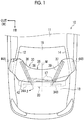
- FIG. 1 A front portion of a vehicle 10 according to the embodiment is illustrated in FIG. 1 .
- the vehicle 10 is configured to include front pillars 12, 14, windshield glass 16, wipers 17, a hood 18, a cowl portion 20, and an airbag device 30 as an example of the airbag device for pedestrian protection.
- the windshield glass 16 is an example of a windshield.
- the airbag device 30 is to suppress contact between a pedestrian's head and a front portion of a vehicle body 11, which is made up mainly of the front pillars 12, 14.
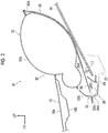
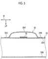
- the hood 18 illustrated in FIG. 2 is disposed above an engine compartment (not illustrated).
- a hood outer panel 18A and a hood inner panel 18B constitute the hood 18 by their outer peripheral edge portions being bound to each other.
- the hood outer panel 18A forms a design surface, and the hood inner panel 18B is disposed on the vehicle lower side of the hood outer panel 18A.
- the hood outer panel 18A and the hood inner panel 18B are formed by, for example, press forming of steel plates.
- the cowl portion 20 is disposed on the vehicle rear side of the hood 18 and above a dash panel (not illustrated) partitioning the engine compartment and the cabin of the vehicle from each other.
- the cowl portion 20 extends in the vehicle width direction.
- the cowl portion 20 is configured to include a cowl panel 22 and a cowl front panel 24, which is bound to an upper end portion of the cowl panel 22 and disposed ahead of the windshield glass 16 on the front side of the vehicle.
- Each member constituting the cowl portion 20 is formed by, for example, press forming of a steel plate.
- An airbag case 32 is disposed in the cowl portion 20.
- the airbag device 30 illustrated in FIG. 2 is arranged on an upper surface of the cowl front panel 24 and is stored in the airbag case 32.
- the airbag device 30 is configured to include a pair of right and left inflators 34B, 34A (refer to FIG. 1 ), an airbag 35, straps 36, 37 (refer to FIG. 1 ), and strap covers 38, 39 (refer to FIG. 1 ).
- a state where the airbag 35 is deployed is illustrated in FIG. 2 .
- the airbag case 32 has a lower case 32A and an upper case 32B and extends in the vehicle width direction.
- the lower case 32A illustrated in FIG. 2 is formed by, for example, press forming of a sheet metal.
- the lower case 32A has a substantially hat shape with its vehicle upper side open.
- the upper case 32B is formed from, for example, a thermoplastic olefin-based material (TPO material).
- TPO material thermoplastic olefin-based material
- the lower case 32A and the upper case 32B are bound to each other by means such as pawl engagement and a double-sided adhesive tape with their respective flange portions superposed on each other.
- the airbag case 32 has the shape of a hollow body that has a substantially rectangular shape when viewed from the vehicle width direction. Illustrated in FIG. 2 is a state where the upper case 32B is broken into two by the airbag 35 being deployed.
- the inflator 34A is disposed on the left side with respect to a center line M, which is in the center of the vehicle 10 in the vehicle width direction.
- the inflator 34B is disposed on the right side with respect to the center line M.
- the inflators 34A, 34B are spaced apart from each other in the vehicle width direction in the airbag case 32 (refer to FIG. 2 ).
- the inflators 34A, 34B are cylinder-type inflators and are disposed in a certain posture such that their axial directions are substantially along the vehicle width direction.
- Each of the inflators 34A, 34B is connected to a gas inlet (not illustrated) disposed in the airbag 35.
- the inflators 34A, 34B are fastened to the cowl front panel 24 (refer to FIG. 2 ) along with the lower case 32A (refer to FIG. 2 ).
- the inflators 34A, 34B are electrically connected to a controller (not illustrated).
- the controller is electrically connected to a collision detection sensor (not illustrated) or a collision prediction sensor (not illustrated) arranged in the vehicle 10.
- the controller Upon detecting a collision, the controller outputs an operation signal to the inflators 34A, 34B.
- a gas is blown into the airbag 35 from gas blowing units of the inflators 34A, 34B, and then inflation deployment of the airbag 35 is performed.
- the upper case 32B comes into contact with the airbag 35 and is broken into two in the vehicle up-down direction.
- the airbag 35 has the shape of a bag with, for example, outer peripheral portions of two cloths rarely permeated by a gas sewn to each other in a state where they are superposed on each other in the vehicle up-down direction.
- the airbag 35 is configured to include a lower cloth 35A disposed on the lower side in the vehicle up-down direction and an upper cloth 35B disposed above the lower cloth 35A and sewn to the lower cloth 35A.
- a tether (not illustrated), which is a partition cloth functioning as a partition wall, is disposed inside the airbag 35. In the inflation deployment state, tension acts on the tether inside the airbag 35, resulting in formation of small and large space portions.
- the airbag 35 in its inflation deployment state has a substantially U-shape, with its vehicle rear side open, in plan view of the vehicle.
- the airbag 35 has an general portion 42, an extending portion 44A, and an extending portion 44B.
- the general portion 42 extends in the vehicle width direction and covers a part of the cowl portion 20 from the upper side of the vehicle.
- the extending portion 44A extends along the front pillar 12 from a left side end portion of the general portion 42 in the vehicle width direction.
- the extending portion 44B extends along the front pillar 14 from a right side end portion of the general portion 42 in the vehicle width direction.
- the extending portions 44A, 44B are disposed in bilateral symmetry with respect to the center line M described above. Tips of the extending portions 44A, 44B are positioned outside their base ends (general portion 42 sides) in the vehicle width direction.
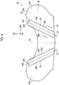
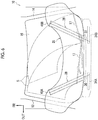
- FIG. 4 Illustrated in FIG. 4 is a state where the lower cloth 35A of the airbag 35 is viewed from the rear side in the front-rear direction of the vehicle.
- Overhanging portions 46A, 46B overhanging toward the center line M are formed at parts of peripheral edge portions of the extending portions 44A, 44B that are on the inner sides in the vehicle width direction.
- the overhanging portions 46A, 46B are examples of an upper portion of the airbag 35 in the vehicle up-down direction.
- Each of the overhanging portions 46A, 46B has a substantially trapezoidal shape.
- the overhanging portion 46A is disposed on the right side that is illustrated in FIG. 4 (left side of the vehicle 10 (refer to FIG. 1 )).
- the overhanging portion 46B is disposed on the left side that is illustrated in FIG. 4 (right side of the vehicle 10 (refer to FIG. 1 )).
- the strap 36 is disposed on the left side (right side in FIG. 4 ) with respect to the center line M.
- the strap 36 has the shape of a rectangular band by, for example, weaving of a plurality of polyester yarns.
- a first end of the strap 36 (on the upper side in the vehicle up-down direction) in its extension direction (longitudinal direction) is sewn to the overhanging portion 46A of the lower cloth 35A.
- a second end of the strap 36 (on the lower side in the vehicle up-down direction) in its extension direction has an annular shape or the like and is attached to the inflator 34A (refer to FIG. 1 ).
- the second end of the strap 36 is attached to the cowl portion 20 (refer to FIG. 1 ).
- the first end of the strap 36 is positioned outside the second end in the vehicle width direction.
- a length over which the tension acts on the strap 36 when the deployment of the airbag 35 is completed is set as the length of the strap 36 in its extension direction.
- the strap 36 in the inflation deployment state of the airbag 35 is stretched between the overhanging portion 46A and the inflator 34A (refer to FIG. 1 ).
- the extending portion 44A does not move outside a position facing the front pillar 12 (refer to FIG. 1 ) in the vehicle width direction.
- the strap 37 is disposed on the right side (left side in FIG. 4 ) with respect to the center line M.
- the strap 37 is formed similarly to the strap 36.
- a first end of the strap 37 (on the upper side in the vehicle up-down direction) in its extension direction (longitudinal direction) is sewn to the overhanging portion 46B of the lower cloth 35A.
- a second end of the strap 37 (on the lower side in the vehicle up-down direction) in its extension direction has an annular shape or the like and is attached to the inflator 34B (refer to FIG. 1 ).
- the second end of the strap 37 is attached to the cowl portion 20 (refer to FIG. 1 ).
- the first end of the strap 37 is positioned outside the second end in the vehicle width direction.
- a length over which the tension acts on the strap 37 when the deployment of the airbag 35 is completed is set as the length of the strap 37 in its extension direction.
- the strap 37 in the inflation deployment state of the airbag 35 is stretched between the overhanging portion 46B and the inflator 34B (refer to FIG. 1 ).
- the extending portion 44B does not move outside a position facing the front pillar 14 (refer to FIG. 1 ) in the vehicle width direction.
- the overhanging portion 46A and the overhanging portion 46B of the airbag 35 are disposed within a wiping range S in the deployment state of the airbag 35.
- the wiping range S is the range of the windshield glass 16 that is covered by wiping by the wipers 17.
- the straps 36, 37 are configured to connect the inflators 34A, 34B and the overhanging portions 46A, 46B to each other, and thus the straps 36, 37 are disposed within the wiping range S during the deployment of the airbag 35.
- the strap cover 38 has a semi-cylindrical portion 38A, sewing portions 38B, 38C, and a sewing portion 38D when viewed from a plane orthogonal to the longitudinal direction.
- the sewing portions 38B, 38C are formed in both end portions of the semi-cylindrical portion 38A in the vehicle width direction.
- the strap cover 38 will be described later (refer to FIG. 4 ).
- the semi-cylindrical portion 38A is a hollow part that is convex toward the lower side in the vehicle up-down direction and the rear side in the vehicle front-rear direction from the lower cloth 35A of the airbag 35.
- the semi-cylindrical portion 38A has a longitudinal length that falls short of the length of the strap 36 in its extension direction and is almost equal to the length between the overhanging portion 46A and the general portion 42 of the airbag 35 (refer to FIG. 4 ).
- the space that is inside the semi-cylindrical portion 38A has a size that does not restrict the elongation (deployment) of the strap 36 during the inflation deployment of the airbag 35.
- the sewing portions 38B, 38C are, for example, band-shaped parts as illustrated in FIG. 4 .
- the sewing portions 38B, 38C are sewn to an outer surface 45, which is an outer peripheral surface of the lower cloth 35A of the airbag 35.
- the strap cover 38 is sewn to the outer surface 45.
- the sewing portions 38B, 38C have a longitudinal length that falls short of the length of the strap 36 in its extension direction and is almost equal to the length of the semi-cylindrical portion 38A. In a state where the strap 36 is stretched, the distance from the strap 36 to the sewing portion 38B is, for example, almost equal to the distance from the strap 36 to the sewing portion 38C.
- the sewing portion 38B and the sewing portion 38C are almost axisymmetrically disposed, about the central axis of the strap 36 as an axis of symmetry, except a first end portion and a second end portion in the longitudinal direction.
- the sewing portion 38D is a band-shaped part that connects a first end of the sewing portion 38B (on the upper side in the vehicle up-down direction, that is, the overhanging portion 46A side) and a first end of the sewing portion 38C (on the upper side in the vehicle up-down direction, that is, the overhanging portion 46A side) to each other.
- a first end of the strap cover 38 is, for example, sewn to the airbag 35.
- a second end of the strap cover 38 that is on the side opposite to the first end is, for example, loose without being sewn to the airbag 35.
- the semi-cylindrical portion 38A covers most of the strap 36 in its extension direction.
- the strap cover 39 is disposed such that it is axisymmetric with the strap cover 38 about the center line M as an axis of symmetry.
- the strap cover 39 has a semi-cylindrical portion 39A, sewing portions 39B, 39C, and a sewing portion 39D (described later).
- the sewing portions 39B, 39C are formed in both end portions of the semi-cylindrical portion 39A in the vehicle width direction.
- the semi-cylindrical portion 39A is a hollow part that is convex toward the lower side in the vehicle up-down direction and the rear side in the vehicle front-rear direction from the lower cloth 35A of the airbag 35.
- the semi-cylindrical portion 39A has a longitudinal length that falls short of the length of the strap 37 in its extension direction and is almost equal to the length between the overhanging portion 46B and the general portion 42 of the airbag 35.
- the space that is inside the semi-cylindrical portion 39A has a size that does not restrict the elongation (deployment) of the strap 37 during the inflation deployment of the airbag 35.
- the sewing portions 39B, 39C are, for example, band-shaped parts.
- the sewing portions 39B, 39C are sewn to the outer surface 45 of the lower cloth 35A.
- the strap cover 39 is sewn to the outer surface 45.
- the sewing portions 39B, 39C have a longitudinal length that falls short of the length of the strap 37 in its extension direction and is almost equal to the length of the semi-cylindrical portion 39A.
- the distance from the strap 37 to the sewing portion 39B is, for example, almost equal to the distance from the strap 37 to the sewing portion 39C.
- the sewing portion 39B and the sewing portion 39C are almost axisymmetrically disposed, about the central axis of the strap 37 as an axis of symmetry, except a first end portion and a second end portion in the longitudinal direction.
- the sewing portion 39D is a band-shaped part that connects a first end of the sewing portion 39B (on the upper side in the vehicle up-down direction, that is, the overhanging portion 46B side) and a first end of the sewing portion 39C (on the upper side in the vehicle up-down direction, that is, the overhanging portion 46B side) to each other.
- a first end of the strap cover 39 is, for example, sewn to the airbag 35.
- a second end of the strap cover 39 is, for example, loose without being sewn to the airbag 35.
- the semi-cylindrical portion 39A covers most of the strap 37 in its extension direction.
- the second end of the strap 36 in its extension direction is exposed from the second end of the strap cover 38 and is attached to the inflator 34A (refer to FIG. 1 ) as described above.
- the second end of the strap 37 in its extension direction is exposed from the second end of the strap cover 39 and is attached to the inflator 34B (refer to FIG. 1 ) as described above.
- the straps 36, 37 and the strap covers 38, 39 are disposed on, for example, the lower cloth 35A side (lower side in the vehicle up-down direction with respect to the airbag 35).
- the straps 36, 37 pass between the airbag 35 and the strap covers 38, 39.
- the strap 36 and the strap cover 38 that are illustrated in FIG. 4 and the strap 37 and the strap cover 39 that are illustrated in FIG. 4 are disposed in bilateral symmetry with respect to the center line M and have the same configuration as each other. Accordingly, the strap 36 and the strap cover 38 will be described below with description of the strap 37 and the strap cover 39 omitted.
- the airbag device 30 is operated once a collision sensor (not illustrated) disposed in a front end portion of the vehicle 10 detects a collision with a pedestrian during traveling of the vehicle 10 illustrated in FIG. 1 .
- the airbag 35 is inflated by the gas being supplied into the airbag 35 from the inflators 34A, 34B.
- the inflated airbag 35 is deployed on the front surface side of the windshield glass 16 with the upper case 32B broken and covers a part of the cowl portion 20, a part of the front pillar 12, and a part of the front pillar 14 (refer to FIG. 1 ).
- the strap 36 is disposed between the airbag 35 and the strap cover 38 in the airbag device 30 and the strap 36 is covered by the strap cover 38. Accordingly, in a case where the airbag 35 is deployed and the strap 36 is elongated, intrusion of another member into the space between the airbag 35 and the strap 36 is restricted by the strap cover 38.
- Intrusion of another member into the space between the airbag 35 and the strap cover 38 is also restricted since the strap cover 38 is sewn to the airbag 35.
- catching of the strap 36 by another member during the deployment of the airbag 35 can be further suppressed than in a configuration lacking the strap cover 38, and thus inhibition of the deployment of the airbag 35 by the strap 36 can be suppressed.
- the strap 36 and the strap cover 38 are disposed on the lower side in the vehicle up-down direction with respect to the airbag 35. Accordingly, in a case where the airbag 35 is deployed, intrusion of the wipers 17 into the space between the airbag 35 and the strap 36 can be restricted by the strap cover 38. As a result, catching of the strap 36 by the wipers 17 can be further suppressed than in a configuration lacking the strap cover 38.
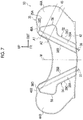
- FIG. 7 Illustrated in FIG. 7 is an airbag device 50 as an example of the airbag device for pedestrian protection according to the second embodiment.
- the airbag device 50 is arranged on the upper surface of the cowl front panel 24 (refer to FIG. 2 ) and stored in the airbag case 32 (refer to FIG. 2 ).
- the airbag device 50 is configured to include the inflators 34A, 34B (refer to FIG. 2 ), the airbag 35, the straps 36, 37, and strap covers 52, 54.
- the strap 36 and the strap cover 52 are disposed in bilateral symmetry with the strap 37 and the strap cover 54 with respect to the center line M and have the same configuration as the strap 37 and the strap cover 54. Accordingly, the strap 36 and the strap cover 52 will be described below with description of the strap 37 and the strap cover 54 omitted.
- the strap cover 52 has, for example, the semi-cylindrical portion 38A, the sewing portions 38B, 38C, and a widened portion 56 (described later).
- the semi-cylindrical portion 38A constitutes the section of the strap cover 52 that ranges from its first end portion (end portion on the overhanging portion 46A side) to its second end portion (end portion on the inflator 34A (refer to FIG. 1 ) side).
- the strap cover 52 has a longitudinal length that falls short of the length of the strap 36 in its extension direction and is almost equal to the length between the overhanging portion 46A and the general portion 42 of the airbag 35.
- the widened portion 56 is disposed in the strap cover 52.
- the widened portion 56 is, for example, a hollow part widened in the direction intersecting with the extension direction of the strap 36 (direction almost orthogonal to the extension direction of the strap 36) on a plane including the strap 36 from the semi-cylindrical portion 38A between the center of the strap cover 52 in the longitudinal direction and the first end portion.
- the widened portion 56 is a part wider than the rest of the strap cover 52 (parts other than the widened portion 56).
- the space that is inside the widened portion 56 has a size that does not restrict the elongation (deployment) of the strap 36 during the inflation deployment of the airbag 35.
- the widened portion 56 is, for example, a trapezoidal part widened toward the outer side in the vehicle width direction and the side that is opposite to the overhanging portion 46A side with respect to the strap 36.
- a part of the sewing portion 38C constitutes an outer edge portion of the widened portion 56.
- a part of the sewing portion 38C is shaped such that it is curved along the widened portion 56.
- a first end of the strap cover 52 is, for example, sewn to the airbag 35.
- a second end of the strap cover 52 is, for example, loose without being sewn to the airbag 35.
- the airbag 35 is folded in accordance with a plurality of mountain and valley lines, including a mountain line A1 and a valley line A2 illustrated in FIG. 7 , and is stored in the airbag case 32 (refer to FIG. 2 ).
- the mountain line A1 extends along, for example, the direction almost orthogonal to the longitudinal direction of the strap cover 52 from the overhanging portion 46A to the part of the extending portion 44A that is on the side which is opposite to the overhanging portion 46A side.
- the valley line A2 is, for example, set further on the inflator 34A (refer to FIG. 1 ) side than the mountain line A1 is and extends substantially in parallel to the mountain line A1.
- the strap cover 52 is folded in at least two places, including the mountain line A1 and the valley line A2.
- the airbag 35, the strap 36, and the strap cover 52 illustrated in FIG. 7 are folded in accordance with the plurality of mountain and valley lines including the mountain line A1 and the valley line A2 and are stored in the airbag case 32 (refer to FIG. 2 ) in the cowl portion 20.
- the second end of the strap 36 is attached to the inflator 34A (refer to FIG. 2 ).
- the size of the space between the strap 36 and the strap cover 52 is larger in the widened portion 56 than at the part other than the widened portion 56.
- the strap 36 and the strap cover 52 are less likely to come into contact with each other than in a configuration in which the strap cover 52 maintains the same width in the extension direction of the strap 36. Then, a frictional force acting on the strap 36 decreases. As a result, work for pulling the strap 36 to the second end is performed with ease in a state where the airbag 35, the strap 36, and the strap cover 52 are folded.
- the airbag device 50 is completed by the folded airbag 35, the folded strap 36, and the folded strap cover 52 being stored in the airbag case 32 (refer to FIG. 2 ).
- the airbag 35 of the airbag device 50 is inflated in a case where a collision between a pedestrian and the vehicle 10 (refer to FIG. 1 ) is detected. After the inflation, the airbag 35 is deployed on the front surface side of the windshield glass 16 (refer to FIG. 1 ) and covers the cowl portion 20, the front pillar 12, and the front pillar 14 in part (refer to FIG. 1 ).
- the strap 36 is disposed between the airbag 35 and the strap cover 52 and the strap 36 is covered by the strap cover 52. Accordingly, in a case where the airbag 35 is deployed and the strap 36 is elongated, intrusion of another member (such as the wipers 17 (refer to FIG. 1 )) into the space between the airbag 35 and the strap 36 is restricted by the strap cover 52.
- another member such as the wipers 17 (refer to FIG. 1 )
- Intrusion of another member into the space between the airbag 35 and the strap cover 52 is also restricted since the strap cover 52 is sewn to the airbag 35.
- catching of the strap 36 by another member during the deployment of the airbag 35 can be further suppressed than in a configuration lacking the strap cover 52, and thus inhibition of the deployment of the airbag 35 by the strap 36 can be suppressed.
- the airbag 35 may be formed in a bag shape by the outer peripheral portions being woven without sewing.
- the airbag 35 may cover the front pillars 12, 14 in whole.
- the disposition of the straps 36, 37 and the strap covers 38, 39, 52, 54 is not limited to the lower cloth 35A side (lower side in the vehicle up-down direction with respect to the airbag 35).
- the straps 36, 37 and the strap covers 38, 39, 52, 54 may be disposed on the upper cloth 35B side (upper side in the vehicle up-down direction with respect to the airbag 35).
- the straps 36, 37 are covered by the strap covers 38, 39, 52, 54 during the inflation deployment of the airbag 35, and thus catching of the straps 36, 37 by the hood 18 is suppressed.
- inhibition of the deployment of the airbag 35 by the straps 36, 37 can be suppressed.
- Ends of the strap covers 38, 39, 52, 54 may be loose without sewing.
- the widened portion 56 may be widened toward the overhanging portion 46A side and the inner side in the vehicle width direction with respect to the strap 36.
- the shape of the widened portion 56 is not limited to the trapezoidal shape, and it may be a polygonal shape such as a semicircular shape and a triangular shape.
- the widened portion 56 does not necessarily have to be integrated with the strap covers 52, 54.
- the widened portion 56 may be combined, as a separate body, with the strap covers 52, 54 by means such as sewing and adhesion.
Landscapes
- Engineering & Computer Science (AREA)
- Mechanical Engineering (AREA)
- Air Bags (AREA)
Claims (12)
- Airbagvorrichtung (30) zum Fußgängerschutz, umfassend:einen Airbag (35), der konfiguriert ist, um in einem Motorhaubenabschnitt (20) gelagert zu sein, wobei der Airbag (35) konfiguriert ist, um an einer vorderen Oberflächenseite einer Windschutzscheibe zum Einsatz zu kommen und um den Motorhaubenabschnitt (20) und die Frontsäulen (12, 14) zumindest teilweise abzudecken; undRiemen (36, 37), wobei ein erstes Ende von jedem der Riemen (36, 37) an einem oberen Abschnitt einer Außenfläche des Airbags (35) in einer von oben nach unten verlaufenden Richtung des Fahrzeugs befestigt ist, und ein zweites Ende von jedem der Riemen (36, 37) an dem Motorhaubenabschnitt (20) befestigt werden kann;dadurch gekennzeichnet, dass die Airbagvorrichtung (30) ferner Folgendes umfasst:
Riemenabdeckungen (38, 39), die an die Außenfläche des Airbags (35) genäht sind und die Riemen (36, 37) abdecken, wobei die Riemen (36, 37) zwischen dem Airbag (35) und den Riemenabdeckungen (38, 39) verlaufen. - Airbagvorrichtung (30) nach Anspruch 1, wobei der Airbag (35) ein unteres Gewebe (35A) und ein oberes Gewebe (35B) beinhaltet, das an das untere Gewebe (35A) genäht ist und über dem unteren Gewebe (35A) in der von oben nach unten verlaufenden Richtung des Fahrzeugs angeordnet ist und die Riemenabdeckungen (38, 39) an eine Außenfläche (45) des unteren Gewebes (35A) genäht sind.
- Airbagvorrichtung (30) nach Anspruch 1 oder 2, wobei die Riemenabdeckungen (38, 39) erweiterte Abschnitte (56) beinhalten, die weiter als die anderen Teile in Richtungen sind, die sich mit Erstreckungsrichtungen der Riemen (36, 37) schneiden.
- Airbagvorrichtung (30) nach Anspruch 3, wobei der erweiterte Abschnitt (56) zwischen dem ersten Ende des Riemens (36) und einer Mitte der Riemenabdeckungen (38, 39) in einer Längsrichtung bereitgestellt ist.
- Airbagvorrichtung (30) nach Anspruch 2, wobei die Riemenabdeckungen (38, 39) einen halbzylindrischen Abschnitt (38A), der zu einer unteren Seite in der von oben nach unten verlaufenden Richtung des Fahrzeugs und einer hinteren Seite in einer von vorne nach hinten verlaufenden Richtung des Fahrzeugs konvex ist, und Nähabschnitte (38B, 38C) beinhalten, die in beiden Endabschnitten des halbzylindrischen Abschnitts (38A) in einer Fahrzeugbreitenrichtung gebildet sind und an die Außenfläche (45) des unteren Gewebes (35A) des Airbags (35) von einer Ebene betrachtet, die orthogonal zu einer Längsrichtung der Riemenabdeckungen ist, genäht ist.
- Airbagvorrichtung (30) nach Anspruch 5, wobei die Nähabschnitte (38B, 38C) eine Längslänge haben, die eine Länge der Riemen (36, 37) in einer Erstreckungsrichtung unterschreitet und gleich einer Länge des halbzylindrischen Abschnitts (38A) ist.
- Airbagvorrichtung (30) nach Anspruch 1, wobei, in einem Aufblasentfaltungszustand des Airbags (35), der Airbag (35) eine U-Form in einer Fahrzeug-Draufsicht hat, wobei eine Fahrzeug-Rückseite des Airbags (35) offen ist und der Airbag (35) einen allgemeinen Abschnitt (42), der sich in eine Fahrzeugbreitenrichtung erstreckt und konfiguriert ist, um einen Teil des Motorhaubenabschnitts (20) von einer Fahrzeugoberseite abzudecken, Erstreckungsabschnitte (44A, 44B), die in bilateraler Symmetrie in Bezug auf eine Mittellinie des Airbags (35) angeordnet sind und entsprechend konfiguriert sind, um sich entlang der Frontsäulen (12, 14) von einem Endabschnitt der linken Seite des allgemeinen Abschnitts (42) in der Fahrzeugbreitenrichtung und einem Endabschnitt der rechten Seite des allgemeinen Abschnitts (42) in der Fahrzeugbreitenrichtung zu erstrecken, und überstehende Abschnitte (46A, 46B) beinhaltet, die zu der Mittellinie in Umfangskantenabschnitten der Erstreckungsabschnitte (44A, 44B) und an Innenseiten in der Fahrzeugbreitenrichtung überstehen.
- Airbagvorrichtung (30) nach Anspruch 7, wobei, in dem Aufblasentfaltungszustand des Airbags (35), Spitzen der Erstreckungsabschnitte (44A, 44B) außerhalb des allgemeinen Abschnitts (42) in der Fahrzeugbreitenrichtung positioniert sind.
- Airbagvorrichtung (30) nach Anspruch 7 oder 8, wobei, in dem Aufblasentfaltungszustand des Airbags (35), der obere Abschnitt der Außenfläche (45) des Airbags (35) in der von oben nach unten verlaufenden Richtung des Fahrzeugs die überstehenden Abschnitte (46A, 46B) ist.
- Airbagvorrichtung (30) nach einem der Ansprüche 7 bis 9, wobei, in dem Aufblasentfaltungszustand des Airbags (35), die überstehenden Abschnitte (46A, 46B) eine Trapezform haben.
- Airbagvorrichtung (30) nach einem der Ansprüche 7 bis 10, wobei, in dem Aufblasentfaltungszustand des Airbags (35), ein erstes Ende der Riemenabdeckungen (38, 39) in einer Längsrichtung an die überstehenden Abschnitte (46A, 46B) des Airbags (35) genäht ist und ein zweites Ende der Riemenabdeckungen (38, 39) in der Längsrichtung an Seiten, die gegenüber dem ersten Ende der Riemenabdeckungen (38, 39) sind, lose ist, ohne an den Airbag (35) genäht zu sein.
- Airbagvorrichtung (30) nach einem der Ansprüche 7 bis 11, wobei die Riemen (36, 37) konfiguriert sind, um in einem Wischbereich (S) der Windschutzscheibe im Aufblasentfaltungszustand des Airbags (35) angeordnet zu sein.
Applications Claiming Priority (1)
| Application Number | Priority Date | Filing Date | Title |
|---|---|---|---|
| JP2016200209A JP6540649B2 (ja) | 2016-10-11 | 2016-10-11 | 歩行者保護用エアバッグ装置 |
Publications (2)
| Publication Number | Publication Date |
|---|---|
| EP3309017A1 EP3309017A1 (de) | 2018-04-18 |
| EP3309017B1 true EP3309017B1 (de) | 2019-04-24 |
Family
ID=59901434
Family Applications (1)
| Application Number | Title | Priority Date | Filing Date |
|---|---|---|---|
| EP17191638.0A Not-in-force EP3309017B1 (de) | 2016-10-11 | 2017-09-18 | Airbagvorrichtung für fussgängerschutz |
Country Status (4)
| Country | Link |
|---|---|
| US (1) | US10507788B2 (de) |
| EP (1) | EP3309017B1 (de) |
| JP (1) | JP6540649B2 (de) |
| CN (1) | CN107933486B (de) |
Families Citing this family (9)
| Publication number | Priority date | Publication date | Assignee | Title |
|---|---|---|---|---|
| US20190084521A1 (en) * | 2017-09-18 | 2019-03-21 | Ford Global Technologies, Llc | Vehicle airbag assembly |
| JP6971200B2 (ja) * | 2018-06-04 | 2021-11-24 | 本田技研工業株式会社 | 衝突物保護装置 |
| CN109591755B (zh) * | 2019-01-14 | 2021-02-19 | 长沙理工大学 | 一种高速轿车保护人地碰撞损伤的方法 |
| CN111469799B (zh) * | 2020-03-20 | 2022-09-27 | 浙江吉利汽车研究院有限公司 | 一种用于保护行人大腿、胯部和肋骨的装置、系统及方法 |
| JP7583567B2 (ja) * | 2020-09-25 | 2024-11-14 | 株式会社Subaru | 車両の車外保護装置 |
| US12172596B2 (en) * | 2020-10-26 | 2024-12-24 | Autoliv Development Ab | Air bag device for pedestrian protection and method for producing same |
| JP2023128139A (ja) * | 2022-03-03 | 2023-09-14 | 本田技研工業株式会社 | エアバッグシステム、物体保護方法及びプログラム |
| KR20240006940A (ko) * | 2022-07-07 | 2024-01-16 | 현대모비스 주식회사 | 외장 에어백장치 |
| JP7823564B2 (ja) * | 2022-12-28 | 2026-03-04 | 豊田合成株式会社 | 歩行者保護装置 |
Family Cites Families (17)
| Publication number | Priority date | Publication date | Assignee | Title |
|---|---|---|---|---|
| JP2004338676A (ja) * | 2003-05-19 | 2004-12-02 | Takata Corp | 外面展開型エアバッグ装置 |
| DE10341368A1 (de) * | 2003-09-03 | 2005-04-07 | Takata-Petri Ag | Sicherheitseinrichtung an einem Kraftfahrzeug zum Schutz von Fußgängern und Radfahrern |
| JP4517873B2 (ja) * | 2005-02-14 | 2010-08-04 | マツダ株式会社 | 車両用歩行者保護装置 |
| JP4492529B2 (ja) * | 2005-12-02 | 2010-06-30 | 豊田合成株式会社 | 歩行者用エアバッグ装置 |
| JP4893043B2 (ja) * | 2006-01-17 | 2012-03-07 | タカタ株式会社 | 歩行者用エアバッグ装置 |
| JP2008222148A (ja) | 2007-03-15 | 2008-09-25 | Honda Motor Co Ltd | 歩行者保護用エアバッグ装置 |
| JP4937831B2 (ja) * | 2007-05-16 | 2012-05-23 | タカタ株式会社 | エアバッグ装置のテザー取付方法 |
| US8016066B1 (en) * | 2010-06-10 | 2011-09-13 | Trw Vehicle Safety Systems Inc. | Pedestrian air bag |
| US8678431B2 (en) * | 2010-10-27 | 2014-03-25 | Trw Vehicle Safety Systems | Air bag with tether and pulley arrangement |
| DE102011085330A1 (de) * | 2011-01-27 | 2012-08-02 | Takata-Petri Ag | Gassackanordnung für ein Kraftfahrzeug |
| EP2502794B1 (de) * | 2011-03-25 | 2013-12-11 | Autoliv Development AB | Fußgänger-Airbaganordnung |
| EP2524843B1 (de) * | 2011-05-20 | 2014-11-19 | Autoliv Development AB | Rückholvorrichtung für ein Fussgängerairbag |
| EP2599669B1 (de) * | 2011-11-29 | 2015-07-22 | Volvo Car Corporation | Fußgänger-Schutzairbag |
| DE102012222006A1 (de) * | 2012-02-29 | 2013-08-29 | Takata AG | Gassackanordnungen für ein Kraftfahrzeug |
| US9511739B2 (en) | 2013-05-08 | 2016-12-06 | GM Global Technology Operations LLC | Fender located pedestrian protection airbag |
| JP6012797B2 (ja) * | 2015-03-09 | 2016-10-25 | 富士重工業株式会社 | 車外用エアバッグ |
| JP6600993B2 (ja) * | 2015-03-09 | 2019-11-06 | Joyson Safety Systems Japan株式会社 | 歩行者用エアバッグ装置 |
-
2016
- 2016-10-11 JP JP2016200209A patent/JP6540649B2/ja active Active
-
2017
- 2017-09-15 US US15/705,574 patent/US10507788B2/en not_active Expired - Fee Related
- 2017-09-18 EP EP17191638.0A patent/EP3309017B1/de not_active Not-in-force
- 2017-09-27 CN CN201710892504.2A patent/CN107933486B/zh not_active Expired - Fee Related
Non-Patent Citations (1)
| Title |
|---|
| None * |
Also Published As
| Publication number | Publication date |
|---|---|
| CN107933486A (zh) | 2018-04-20 |
| JP6540649B2 (ja) | 2019-07-10 |
| US20180099638A1 (en) | 2018-04-12 |
| CN107933486B (zh) | 2020-07-31 |
| JP2018062206A (ja) | 2018-04-19 |
| EP3309017A1 (de) | 2018-04-18 |
| US10507788B2 (en) | 2019-12-17 |
Similar Documents
| Publication | Publication Date | Title |
|---|---|---|
| EP3309017B1 (de) | Airbagvorrichtung für fussgängerschutz | |
| US9776593B2 (en) | Curtain airbag apparatus | |
| US9067563B2 (en) | Head protection airbag apparatus | |
| US8414020B2 (en) | Airbag device | |
| US9771046B2 (en) | Curtain airbag apparatus | |
| US7967098B2 (en) | Exterior airbag cushion for vehicle and device having the same | |
| JP4893043B2 (ja) | 歩行者用エアバッグ装置 | |
| JP5036401B2 (ja) | カーテンサイドエアバッグ装置 | |
| US9550470B2 (en) | Curtain airbag apparatus | |
| JP4175338B2 (ja) | エアバッグ装置 | |
| CN102300750A (zh) | 轿车用头部保护安全气囊装置 | |
| JP3759501B2 (ja) | 乗員拘束装置 | |
| JP2013208979A (ja) | 頭部保護エアバッグ装置 | |
| JP6519275B2 (ja) | エアバッグ及び歩行者用エアバッグ装置 | |
| JP5826093B2 (ja) | 頭部保護エアバッグ装置 | |
| JP2007203956A (ja) | エアバッグ及びエアバッグ装置 | |
| JP4191466B2 (ja) | 乗員拘束装置 | |
| EP2105358B1 (de) | Airbagvorrichtung | |
| JP2006096289A (ja) | 歩行者用エアバッグ装置 | |
| US20150054262A1 (en) | Airbag device for vehicle | |
| JP3605331B2 (ja) | エアバッグ装置 | |
| JP7342899B2 (ja) | 歩行者用エアバッグ | |
| JP5843432B2 (ja) | カーテンエアバッグ装置 | |
| KR102523104B1 (ko) | 커튼 에어백 장치 | |
| JP2007216819A (ja) | カーテンエアバッグ |
Legal Events
| Date | Code | Title | Description |
|---|---|---|---|
| PUAI | Public reference made under article 153(3) epc to a published international application that has entered the european phase |
Free format text: ORIGINAL CODE: 0009012 |
|
| STAA | Information on the status of an ep patent application or granted ep patent |
Free format text: STATUS: REQUEST FOR EXAMINATION WAS MADE |
|
| 17P | Request for examination filed |
Effective date: 20170918 |
|
| AK | Designated contracting states |
Kind code of ref document: A1 Designated state(s): AL AT BE BG CH CY CZ DE DK EE ES FI FR GB GR HR HU IE IS IT LI LT LU LV MC MK MT NL NO PL PT RO RS SE SI SK SM TR |
|
| AX | Request for extension of the european patent |
Extension state: BA ME |
|
| GRAP | Despatch of communication of intention to grant a patent |
Free format text: ORIGINAL CODE: EPIDOSNIGR1 |
|
| STAA | Information on the status of an ep patent application or granted ep patent |
Free format text: STATUS: GRANT OF PATENT IS INTENDED |
|
| INTG | Intention to grant announced |
Effective date: 20190104 |
|
| GRAS | Grant fee paid |
Free format text: ORIGINAL CODE: EPIDOSNIGR3 |
|
| GRAA | (expected) grant |
Free format text: ORIGINAL CODE: 0009210 |
|
| STAA | Information on the status of an ep patent application or granted ep patent |
Free format text: STATUS: THE PATENT HAS BEEN GRANTED |
|
| AK | Designated contracting states |
Kind code of ref document: B1 Designated state(s): AL AT BE BG CH CY CZ DE DK EE ES FI FR GB GR HR HU IE IS IT LI LT LU LV MC MK MT NL NO PL PT RO RS SE SI SK SM TR |
|
| REG | Reference to a national code |
Ref country code: GB Ref legal event code: FG4D |
|
| REG | Reference to a national code |
Ref country code: CH Ref legal event code: EP |
|
| REG | Reference to a national code |
Ref country code: DE Ref legal event code: R096 Ref document number: 602017003488 Country of ref document: DE |
|
| REG | Reference to a national code |
Ref country code: AT Ref legal event code: REF Ref document number: 1123756 Country of ref document: AT Kind code of ref document: T Effective date: 20190515 Ref country code: IE Ref legal event code: FG4D |
|
| REG | Reference to a national code |
Ref country code: DE Ref legal event code: R084 Ref document number: 602017003488 Country of ref document: DE |
|
| REG | Reference to a national code |
Ref country code: GB Ref legal event code: 746 Effective date: 20190716 |
|
| REG | Reference to a national code |
Ref country code: NL Ref legal event code: MP Effective date: 20190424 |
|
| REG | Reference to a national code |
Ref country code: LT Ref legal event code: MG4D |
|
| PG25 | Lapsed in a contracting state [announced via postgrant information from national office to epo] |
Ref country code: NL Free format text: LAPSE BECAUSE OF FAILURE TO SUBMIT A TRANSLATION OF THE DESCRIPTION OR TO PAY THE FEE WITHIN THE PRESCRIBED TIME-LIMIT Effective date: 20190424 |
|
| PG25 | Lapsed in a contracting state [announced via postgrant information from national office to epo] |
Ref country code: LT Free format text: LAPSE BECAUSE OF FAILURE TO SUBMIT A TRANSLATION OF THE DESCRIPTION OR TO PAY THE FEE WITHIN THE PRESCRIBED TIME-LIMIT Effective date: 20190424 Ref country code: HR Free format text: LAPSE BECAUSE OF FAILURE TO SUBMIT A TRANSLATION OF THE DESCRIPTION OR TO PAY THE FEE WITHIN THE PRESCRIBED TIME-LIMIT Effective date: 20190424 Ref country code: SE Free format text: LAPSE BECAUSE OF FAILURE TO SUBMIT A TRANSLATION OF THE DESCRIPTION OR TO PAY THE FEE WITHIN THE PRESCRIBED TIME-LIMIT Effective date: 20190424 Ref country code: PT Free format text: LAPSE BECAUSE OF FAILURE TO SUBMIT A TRANSLATION OF THE DESCRIPTION OR TO PAY THE FEE WITHIN THE PRESCRIBED TIME-LIMIT Effective date: 20190824 Ref country code: NO Free format text: LAPSE BECAUSE OF FAILURE TO SUBMIT A TRANSLATION OF THE DESCRIPTION OR TO PAY THE FEE WITHIN THE PRESCRIBED TIME-LIMIT Effective date: 20190724 Ref country code: ES Free format text: LAPSE BECAUSE OF FAILURE TO SUBMIT A TRANSLATION OF THE DESCRIPTION OR TO PAY THE FEE WITHIN THE PRESCRIBED TIME-LIMIT Effective date: 20190424 Ref country code: AL Free format text: LAPSE BECAUSE OF FAILURE TO SUBMIT A TRANSLATION OF THE DESCRIPTION OR TO PAY THE FEE WITHIN THE PRESCRIBED TIME-LIMIT Effective date: 20190424 Ref country code: FI Free format text: LAPSE BECAUSE OF FAILURE TO SUBMIT A TRANSLATION OF THE DESCRIPTION OR TO PAY THE FEE WITHIN THE PRESCRIBED TIME-LIMIT Effective date: 20190424 |
|
| PG25 | Lapsed in a contracting state [announced via postgrant information from national office to epo] |
Ref country code: BG Free format text: LAPSE BECAUSE OF FAILURE TO SUBMIT A TRANSLATION OF THE DESCRIPTION OR TO PAY THE FEE WITHIN THE PRESCRIBED TIME-LIMIT Effective date: 20190724 Ref country code: GR Free format text: LAPSE BECAUSE OF FAILURE TO SUBMIT A TRANSLATION OF THE DESCRIPTION OR TO PAY THE FEE WITHIN THE PRESCRIBED TIME-LIMIT Effective date: 20190725 Ref country code: RS Free format text: LAPSE BECAUSE OF FAILURE TO SUBMIT A TRANSLATION OF THE DESCRIPTION OR TO PAY THE FEE WITHIN THE PRESCRIBED TIME-LIMIT Effective date: 20190424 Ref country code: LV Free format text: LAPSE BECAUSE OF FAILURE TO SUBMIT A TRANSLATION OF THE DESCRIPTION OR TO PAY THE FEE WITHIN THE PRESCRIBED TIME-LIMIT Effective date: 20190424 Ref country code: PL Free format text: LAPSE BECAUSE OF FAILURE TO SUBMIT A TRANSLATION OF THE DESCRIPTION OR TO PAY THE FEE WITHIN THE PRESCRIBED TIME-LIMIT Effective date: 20190424 |
|
| REG | Reference to a national code |
Ref country code: AT Ref legal event code: MK05 Ref document number: 1123756 Country of ref document: AT Kind code of ref document: T Effective date: 20190424 |
|
| PG25 | Lapsed in a contracting state [announced via postgrant information from national office to epo] |
Ref country code: IS Free format text: LAPSE BECAUSE OF FAILURE TO SUBMIT A TRANSLATION OF THE DESCRIPTION OR TO PAY THE FEE WITHIN THE PRESCRIBED TIME-LIMIT Effective date: 20190824 |
|
| REG | Reference to a national code |
Ref country code: DE Ref legal event code: R097 Ref document number: 602017003488 Country of ref document: DE |
|
| PG25 | Lapsed in a contracting state [announced via postgrant information from national office to epo] |
Ref country code: EE Free format text: LAPSE BECAUSE OF FAILURE TO SUBMIT A TRANSLATION OF THE DESCRIPTION OR TO PAY THE FEE WITHIN THE PRESCRIBED TIME-LIMIT Effective date: 20190424 Ref country code: DK Free format text: LAPSE BECAUSE OF FAILURE TO SUBMIT A TRANSLATION OF THE DESCRIPTION OR TO PAY THE FEE WITHIN THE PRESCRIBED TIME-LIMIT Effective date: 20190424 Ref country code: SK Free format text: LAPSE BECAUSE OF FAILURE TO SUBMIT A TRANSLATION OF THE DESCRIPTION OR TO PAY THE FEE WITHIN THE PRESCRIBED TIME-LIMIT Effective date: 20190424 Ref country code: RO Free format text: LAPSE BECAUSE OF FAILURE TO SUBMIT A TRANSLATION OF THE DESCRIPTION OR TO PAY THE FEE WITHIN THE PRESCRIBED TIME-LIMIT Effective date: 20190424 Ref country code: AT Free format text: LAPSE BECAUSE OF FAILURE TO SUBMIT A TRANSLATION OF THE DESCRIPTION OR TO PAY THE FEE WITHIN THE PRESCRIBED TIME-LIMIT Effective date: 20190424 Ref country code: CZ Free format text: LAPSE BECAUSE OF FAILURE TO SUBMIT A TRANSLATION OF THE DESCRIPTION OR TO PAY THE FEE WITHIN THE PRESCRIBED TIME-LIMIT Effective date: 20190424 |
|
| PG25 | Lapsed in a contracting state [announced via postgrant information from national office to epo] |
Ref country code: SM Free format text: LAPSE BECAUSE OF FAILURE TO SUBMIT A TRANSLATION OF THE DESCRIPTION OR TO PAY THE FEE WITHIN THE PRESCRIBED TIME-LIMIT Effective date: 20190424 Ref country code: IT Free format text: LAPSE BECAUSE OF FAILURE TO SUBMIT A TRANSLATION OF THE DESCRIPTION OR TO PAY THE FEE WITHIN THE PRESCRIBED TIME-LIMIT Effective date: 20190424 |
|
| PLBE | No opposition filed within time limit |
Free format text: ORIGINAL CODE: 0009261 |
|
| STAA | Information on the status of an ep patent application or granted ep patent |
Free format text: STATUS: NO OPPOSITION FILED WITHIN TIME LIMIT |
|
| PG25 | Lapsed in a contracting state [announced via postgrant information from national office to epo] |
Ref country code: TR Free format text: LAPSE BECAUSE OF FAILURE TO SUBMIT A TRANSLATION OF THE DESCRIPTION OR TO PAY THE FEE WITHIN THE PRESCRIBED TIME-LIMIT Effective date: 20190424 |
|
| 26N | No opposition filed |
Effective date: 20200127 |
|
| PG25 | Lapsed in a contracting state [announced via postgrant information from national office to epo] |
Ref country code: SI Free format text: LAPSE BECAUSE OF FAILURE TO SUBMIT A TRANSLATION OF THE DESCRIPTION OR TO PAY THE FEE WITHIN THE PRESCRIBED TIME-LIMIT Effective date: 20190424 Ref country code: MC Free format text: LAPSE BECAUSE OF FAILURE TO SUBMIT A TRANSLATION OF THE DESCRIPTION OR TO PAY THE FEE WITHIN THE PRESCRIBED TIME-LIMIT Effective date: 20190424 |
|
| PG25 | Lapsed in a contracting state [announced via postgrant information from national office to epo] |
Ref country code: LU Free format text: LAPSE BECAUSE OF NON-PAYMENT OF DUE FEES Effective date: 20190918 Ref country code: IE Free format text: LAPSE BECAUSE OF NON-PAYMENT OF DUE FEES Effective date: 20190918 |
|
| REG | Reference to a national code |
Ref country code: BE Ref legal event code: MM Effective date: 20190930 |
|
| PG25 | Lapsed in a contracting state [announced via postgrant information from national office to epo] |
Ref country code: BE Free format text: LAPSE BECAUSE OF NON-PAYMENT OF DUE FEES Effective date: 20190930 |
|
| REG | Reference to a national code |
Ref country code: CH Ref legal event code: PL |
|
| PG25 | Lapsed in a contracting state [announced via postgrant information from national office to epo] |
Ref country code: CY Free format text: LAPSE BECAUSE OF FAILURE TO SUBMIT A TRANSLATION OF THE DESCRIPTION OR TO PAY THE FEE WITHIN THE PRESCRIBED TIME-LIMIT Effective date: 20190424 |
|
| PG25 | Lapsed in a contracting state [announced via postgrant information from national office to epo] |
Ref country code: MT Free format text: LAPSE BECAUSE OF FAILURE TO SUBMIT A TRANSLATION OF THE DESCRIPTION OR TO PAY THE FEE WITHIN THE PRESCRIBED TIME-LIMIT Effective date: 20190424 Ref country code: HU Free format text: LAPSE BECAUSE OF FAILURE TO SUBMIT A TRANSLATION OF THE DESCRIPTION OR TO PAY THE FEE WITHIN THE PRESCRIBED TIME-LIMIT; INVALID AB INITIO Effective date: 20170918 |
|
| PG25 | Lapsed in a contracting state [announced via postgrant information from national office to epo] |
Ref country code: LI Free format text: LAPSE BECAUSE OF NON-PAYMENT OF DUE FEES Effective date: 20200930 Ref country code: CH Free format text: LAPSE BECAUSE OF NON-PAYMENT OF DUE FEES Effective date: 20200930 |
|
| PGFP | Annual fee paid to national office [announced via postgrant information from national office to epo] |
Ref country code: FR Payment date: 20210812 Year of fee payment: 5 |
|
| PGFP | Annual fee paid to national office [announced via postgrant information from national office to epo] |
Ref country code: DE Payment date: 20210810 Year of fee payment: 5 Ref country code: GB Payment date: 20210811 Year of fee payment: 5 |
|
| PG25 | Lapsed in a contracting state [announced via postgrant information from national office to epo] |
Ref country code: MK Free format text: LAPSE BECAUSE OF FAILURE TO SUBMIT A TRANSLATION OF THE DESCRIPTION OR TO PAY THE FEE WITHIN THE PRESCRIBED TIME-LIMIT Effective date: 20190424 |
|
| REG | Reference to a national code |
Ref country code: DE Ref legal event code: R119 Ref document number: 602017003488 Country of ref document: DE |
|
| GBPC | Gb: european patent ceased through non-payment of renewal fee |
Effective date: 20220918 |
|
| PG25 | Lapsed in a contracting state [announced via postgrant information from national office to epo] |
Ref country code: FR Free format text: LAPSE BECAUSE OF NON-PAYMENT OF DUE FEES Effective date: 20220930 Ref country code: DE Free format text: LAPSE BECAUSE OF NON-PAYMENT OF DUE FEES Effective date: 20230401 |
|
| PG25 | Lapsed in a contracting state [announced via postgrant information from national office to epo] |
Ref country code: GB Free format text: LAPSE BECAUSE OF NON-PAYMENT OF DUE FEES Effective date: 20220918 |