EP3307973B1 - Fermeture de fenêtre, de porte ou similaire - Google Patents
Fermeture de fenêtre, de porte ou similaire Download PDFInfo
- Publication number
- EP3307973B1 EP3307973B1 EP16735640.1A EP16735640A EP3307973B1 EP 3307973 B1 EP3307973 B1 EP 3307973B1 EP 16735640 A EP16735640 A EP 16735640A EP 3307973 B1 EP3307973 B1 EP 3307973B1
- Authority
- EP
- European Patent Office
- Prior art keywords
- closure
- motor
- base body
- drive
- accordance
- Prior art date
- Legal status (The legal status is an assumption and is not a legal conclusion. Google has not performed a legal analysis and makes no representation as to the accuracy of the status listed.)
- Active
Links
- 238000006073 displacement reaction Methods 0.000 claims description 39
- 230000005540 biological transmission Effects 0.000 claims description 24
- 230000000903 blocking effect Effects 0.000 claims description 18
- 230000033001 locomotion Effects 0.000 claims description 15
- 230000008878 coupling Effects 0.000 claims description 9
- 238000010168 coupling process Methods 0.000 claims description 9
- 238000005859 coupling reaction Methods 0.000 claims description 9
- 238000006243 chemical reaction Methods 0.000 claims description 5
- 230000008054 signal transmission Effects 0.000 claims description 4
- 230000009471 action Effects 0.000 claims description 3
- 230000004913 activation Effects 0.000 claims 1
- 206010053648 Vascular occlusion Diseases 0.000 description 18
- 230000006835 compression Effects 0.000 description 10
- 238000007906 compression Methods 0.000 description 10
- 238000000034 method Methods 0.000 description 4
- 230000008569 process Effects 0.000 description 4
- 230000003213 activating effect Effects 0.000 description 3
- 238000010276 construction Methods 0.000 description 2
- 238000013461 design Methods 0.000 description 2
- 230000000694 effects Effects 0.000 description 2
- 230000007246 mechanism Effects 0.000 description 2
- 238000013459 approach Methods 0.000 description 1
- 230000008901 benefit Effects 0.000 description 1
- 238000004891 communication Methods 0.000 description 1
- 230000001419 dependent effect Effects 0.000 description 1
- 238000011161 development Methods 0.000 description 1
- 230000018109 developmental process Effects 0.000 description 1
- 238000004146 energy storage Methods 0.000 description 1
- 238000007667 floating Methods 0.000 description 1
- 230000003993 interaction Effects 0.000 description 1
- 230000007935 neutral effect Effects 0.000 description 1
- 238000012546 transfer Methods 0.000 description 1
- 230000007704 transition Effects 0.000 description 1
- 238000009423 ventilation Methods 0.000 description 1
- 230000000007 visual effect Effects 0.000 description 1
Images


Classifications
-
- E—FIXED CONSTRUCTIONS
- E05—LOCKS; KEYS; WINDOW OR DOOR FITTINGS; SAFES
- E05C—BOLTS OR FASTENING DEVICES FOR WINGS, SPECIALLY FOR DOORS OR WINDOWS
- E05C3/00—Fastening devices with bolts moving pivotally or rotatively
- E05C3/12—Fastening devices with bolts moving pivotally or rotatively with latching action
- E05C3/16—Fastening devices with bolts moving pivotally or rotatively with latching action with operating handle or equivalent member moving otherwise than rigidly with the latch
- E05C3/22—Fastening devices with bolts moving pivotally or rotatively with latching action with operating handle or equivalent member moving otherwise than rigidly with the latch the bolt being spring controlled
- E05C3/24—Fastening devices with bolts moving pivotally or rotatively with latching action with operating handle or equivalent member moving otherwise than rigidly with the latch the bolt being spring controlled in the form of a bifurcated member
- E05C3/26—Fastening devices with bolts moving pivotally or rotatively with latching action with operating handle or equivalent member moving otherwise than rigidly with the latch the bolt being spring controlled in the form of a bifurcated member engaging a stud-like keeper
-
- E—FIXED CONSTRUCTIONS
- E05—LOCKS; KEYS; WINDOW OR DOOR FITTINGS; SAFES
- E05B—LOCKS; ACCESSORIES THEREFOR; HANDCUFFS
- E05B17/00—Accessories in connection with locks
- E05B17/0025—Devices for forcing the wing firmly against its seat or to initiate the opening of the wing
- E05B17/0029—Devices for forcing the wing firmly against its seat or to initiate the opening of the wing motor-operated
-
- E—FIXED CONSTRUCTIONS
- E05—LOCKS; KEYS; WINDOW OR DOOR FITTINGS; SAFES
- E05B—LOCKS; ACCESSORIES THEREFOR; HANDCUFFS
- E05B47/00—Operating or controlling locks or other fastening devices by electric or magnetic means
- E05B47/0001—Operating or controlling locks or other fastening devices by electric or magnetic means with electric actuators; Constructional features thereof
- E05B47/0012—Operating or controlling locks or other fastening devices by electric or magnetic means with electric actuators; Constructional features thereof with rotary electromotors
-
- E—FIXED CONSTRUCTIONS
- E05—LOCKS; KEYS; WINDOW OR DOOR FITTINGS; SAFES
- E05B—LOCKS; ACCESSORIES THEREFOR; HANDCUFFS
- E05B47/00—Operating or controlling locks or other fastening devices by electric or magnetic means
- E05B47/06—Controlling mechanically-operated bolts by electro-magnetically-operated detents
-
- E—FIXED CONSTRUCTIONS
- E05—LOCKS; KEYS; WINDOW OR DOOR FITTINGS; SAFES
- E05B—LOCKS; ACCESSORIES THEREFOR; HANDCUFFS
- E05B9/00—Lock casings or latch-mechanism casings ; Fastening locks or fasteners or parts thereof to the wing
- E05B9/08—Fastening locks or fasteners or parts thereof, e.g. the casings of latch-bolt locks or cylinder locks to the wing
Definitions
- the base body can be provided for attachment to the frame and the locking element for attachment to the sash, or vice versa.
- the base body can be used for fastening be formed in a fitting groove of the frame or the sash.
- the locking element can be a simple pin.
- the pin can have a cylindrical cross-section in order to enable particularly easy sliding into the holding receptacle.
- the pin can be mushroom-shaped.
- the closure element can be pivotable between the release position and the blocking position, for example about a pivot axis running transversely to the opening direction. This enables a particularly simple construction.
- the closure element can automatically be moved into the locking position by closing the sash and a renewed opening of the sash is already prevented in this state of the closure, the sash is secured against unwanted opening immediately after the closing process - even if the user only has one Gave a "push".
- the final locking by moving the locking element into the blocking position can take place at any time afterwards, for example by actuating a handle arranged on the frame.
- the closure element In the blocking position, the closure element can block the locking element in and against the opening direction so that the sash is completely fixed on the frame.
- the locking element can also be blocked in certain directions by components of the closure that differ from the closure element.
- One advantage of the latching capability of the closure element in the locking position is that the wing can thus be secured in a gap ventilation position, for example.
- the DE 10 2006 019 515 A1 discloses a closure according to the preamble of claim 1.
- the DE 10 2009 035 737 A1 discloses a two-component door locking system with a motor-driven catch element.
- a locking device for windows and doors is disclosed which is based on the engagement of a sash-side bolt in the recess of a pivotable locking element.
- a closure comprises a motor which is arranged on the base body and which is provided, when activated, to act upon the closure element in the locking position directly or indirectly in such a way that it moves into the blocking position.
- the transition of the wing from the locked state to the fully locked state is therefore carried out by a motor. Therefore, the user does not need to use the force to move the respective components himself. In particular, no actuation of a rotary handle or the like is required. It is thus possible to use a window or window provided with a closure according to the invention a door without a control element, i.e. without a handle. Such windows and doors are particularly visually appealing.
- the assembly of a lock according to the invention is simple, since the motor is integrated into the lock and therefore no mechanical coupling of the lock element with a fitting gear is necessary.
- the main body of a closure according to the invention is designed for fastening in a fitting groove of the frame or of the sash.
- a pawl is movably, in particular pivotably, mounted on the base body, which pawl engages in a latching recess of the closure element to latch the closure element with the base body or engages behind a latching projection of the closure element.
- the pawl is mounted on a displacement unit, which is between a locking position in which an engagement the pawl is made possible in the latching recess or reaching behind the latching projection, and a release position in which the pawl is removed from the latching recess or the latching projection, is mounted displaceably on the base body, the motor being coupled to the displacement unit in a driving manner.
- the motor can be designed as a linear motor.
- the motor has an output shaft that can be driven in rotation and that a spindle drive is provided to convert the rotary movement of the output shaft into a displacement movement of the displacement unit. This enables a particularly simple motorized displacement of the pawl towards the closure element and away from the closure element.
- the pawl is preferably pretensioned with respect to the displacement unit in the direction of the closure element by a spring device, so that in the normal case it automatically comes into engagement with the recess as soon as the closure element has reached the locking position.
- the displacement unit can be displaced beyond the latching position in the direction of the closure element in order to press the closure element into the blocking position by being acted upon by the pawl.
- the pawl can act on a curved outer surface of the pivotable closure element for this purpose, the curvature bringing about or supporting a conversion of the displacement movement of the pawl into a pivoting movement of the closure element.
- the displacement unit is displaceable between three different functional positions, which correspond to an unlocked, a locked and a locked lock.
- the closure is unlocked.
- the pawl is just close enough for a locking engagement with the locking element, the locking is locked.
- the closure is locked.
- the locking pawl can in particular be pressed against the closure element in a jamming or wedging manner when the displacement unit is pushed beyond the latching position in the direction of the closure element.
- the closure element can be pretensioned in the direction of the release position by means of a spring, so that the closure is ready for a renewed locking or blocking after each unlocking process.
- the motor preferably acts on the closure element via a self-locking transmission device.
- the motor can thus be switched off as soon as the closure element has reached the desired position after a motor-driven movement.
- a self-locking spindle drive can be provided as the transmission device.
- the motor is designed as an electric motor, an electrical energy storage device for supplying energy to the electric motor, in particular a battery or accumulator arrangement, being arranged on the base body.
- a lock designed in this way is to a certain extent self-sufficient and in principle does not require any connection to other drive components. Assembly is therefore particularly easy.
- the energy store arranged on the base body is provided for supplying energy to the electric motor.
- the electric motor it is preferred to provide the electric motor with an output-side gear unit, for example based on a planetary gear.
- the base body has a housing section which at least partially encloses the motor and / or the electrical energy store.
- the base body can be designed completely as a housing in which the motor and / or the energy store are accommodated. This means that the motor and the energy store can be fully integrated into the closure.
- the housing-like design of the base body protects the motor from external influences.
- a closure according to the invention can have a preferably wireless signal receiving unit assigned to the motor, by means of which the motor can be remotely controlled. This enables particularly simple operation of the lock, for example by means of a portable control device.
- the signal receiving unit can in particular be based on radio or infrared transmission.
- a lock according to the invention could also be operated via at least one button or the like arranged on the sash or on the frame.
- a preferably wireless signal transmission unit assigned to the motor can be provided for transmitting status information relating to the motor to a further lock or to an external control device.
- This enables z. B. in a window with several closures according to the invention a communication between the closures. In this way, in particular, synchronization of the operation of the individual locks and thus a particularly reliable overall function of a window or door is made possible. It is also easy to control several windows or doors at the same time.
- the signal transmitting unit can be based on radio or infrared transmission.
- a closure according to the invention can also have a remote control unit assigned to the motor, which has both a signal receiving unit and a signal transmitting unit.
- the motor can be effectively coupled to at least one fixing element movably mounted on the main body and is able to move the fixing element into a fixing position during assembly of the lock, in which the main body is fixed on the frame or on the sash.
- This enables the fastener to be fastened quickly and easily to the associated window or door component, and the fastening can even take place automatically.
- Such a closure can be manufactured in a relatively compact and cost-effective manner, since one and the same motor is used both to act on the closure element and to drive the fixing element, that is to say it fulfills a double function.
- a motor could also be provided to act on the closure element and a further motor to drive the fixing element.
- the at least one fixing element is designed for clamping and / or wedging the base body in a fitting groove of the frame or of the sash. This enables a particularly simple design.
- the motor can be coupled with two fixing elements which are effective for driving and which can be moved apart in order to clamp the base body in a fitting groove of the frame or the sash.
- a lock designed in this way can be used in a particularly flexible manner, since it can be mounted on any blind or casement frame that has a common fitting groove.
- the two fixing elements can be designed as elongated clamping rails which extend parallel to one another and which can be moved apart transversely to the rail longitudinal axis.
- the distribution of the clamping force over the length of the clamping rails enables particularly reliable fastening.
- the clamping rails can be moved apart by a transmission element which is displaceable in the direction of the longitudinal axis of the rails and can be coupled to the motor for driving action, a conversion device being provided for converting the longitudinal displacement of the transmission element into a transverse displacement of the clamping rails.
- the displaceable transmission element can be coupled in a simple manner to the output shaft of a motor - for example via a spindle drive.
- the transmission element is preferably slidably guided on or in the base body.
- the relocating device preferably comprises a link control.
- a gate control can be provided in a particularly simple and cost-effective manner and allows complex motion control if required.
- the link control can have at least two guide links with respective self-locking holding sections for fixing the clamping rails in the position that is moved apart. Because of the holding sections, it is not necessary to actively hold the clamping rails in the position that is moved apart. Rather, it is sufficient to move the clamping rails apart once for a permanent attachment of the base body to the relevant frame or casement frame.
- the drive-effective coupling of the motor to the at least one fixing element is preferably releasable.
- the motor can thus be used for other purposes after the lock has been installed, for example for locking and unlocking tasks, without that accidental detachment of the main body from the frame or casement is to be feared.
- a further embodiment of the invention provides that a drive unit comprising the motor is mounted displaceably on the base body in such a way that a drive element of the drive unit can be moved out of engagement with a transmission element in order to release the drive-effective coupling. To decouple the motor from the fixing mechanism, all that is necessary is then to simply move the drive unit.
- the drive unit can be biased by a spring arrangement into a disengaged position in which the drive element and the transmission element are disengaged.
- a drive of the fixing mechanism by the motor is therefore only possible when the drive unit is actively urged against the spring force into an engagement position. This can be done manually by a user.
- an actuating section accessible from the outside can be arranged on the drive unit.
- a separately controllable motor could also be provided to urge the drive unit into the engagement position against the spring force if necessary.
- a lock according to the invention can be designed as a fitting part, in particular as a fitting part for a building window, a building door or the like. Such fittings are usually specially designed for attachment to a frame or sash profile.
- a special embodiment of the invention provides that the closure as a fitting part of a drive rod fitting such.
- a tilt or tilt and turn fitting is designed, which comprises a faceplate and at least one slidably guided on this and the locking element supporting drive rod.
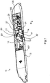
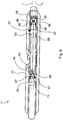
- Fig. 1 shows a fitting part which is designed for attachment to a frame of a window or a door and a closure 11 of the window or the Door forms.
- the closure 11 comprises a housing-like base body 13 with a base plate 14 on which a claw-shaped closure element 15 is pivotably mounted by means of a pivot pin 17.
- the closure element 15 has a receptacle 19 in the form of a groove open on one side.
- the width of the receptacle 19 is dimensioned such that a cylindrical locking element (not shown), which is provided for fastening to the sash of the window or the door, fits into it.
- the base body 13 is designed for attachment to the sash and the locking element is designed for attachment to the frame.
- a latching projection 21 is provided on that side of the closure element 15 which is opposite the receptacle 19 in relation to the pivot pin 17. If necessary, several locking projections could also be arranged one behind the other on the closure element 15.
- a locking pawl 27 for locking engagement with the locking projection 21 is also arranged on the base body 13.
- the pawl 27 is pivotable on one
- the displacement unit 29 is mounted, which in turn is mounted on the base body 13 so as to be linearly displaceable.
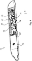
- the displacement unit 29 In the in Fig. 1 and 2 In the operating states of the lock 11 shown, the displacement unit 29 is in a latching position, in which the latching projection 21 can be gripped behind by the pawl 27. In contrast, the displacement unit 29 is located in the in Fig. 4
- the operating state shown of the closure 11 is so far removed from the locking projection 21 that a locking engagement is excluded.
- the pawl 27 is pretensioned with respect to the displacement unit 29 in the direction of the closure element 15.
- the locking element connected to it moves towards the locking element 15 and strikes against the rear stop edge 32 of the receptacle 19. Due to the pressure against the rear stop edge 32, the locking element 15 is pivoted clockwise until it reaches the locking position ( Fig. 2 ) has reached. The sash is then secured against reopening.
- the wing By further pivoting the closure element 15 beyond the locking position, the wing can be closed further and finally completely locked.
- the pivoting of the locking element 15 from the locking position ( Fig. 2 ) to the blocking position ( Fig. 3 ) takes place by direct action on the closure element 15 by means of the pawl 27.
- the displacement unit 29 can be displaced with respect to the base plate 14 beyond the latching position in the direction of the closure element 15.
- the pawl 27 presses against the closure element 15 and holds it in the blocking position.
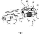
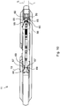
- the locking and unlocking of the lock 11 takes place by a motor 33 integrated in the base body 13, as follows with additional reference to FIG Fig. 5-8 is explained.
- the motor 33 is an electric motor which, together with an auxiliary gear 35, a drive spindle 37 and the previously mentioned, in Fig. 5 Base plate 14, not shown, forms a drive unit 39.
- a battery arrangement 41 ( Fig. 6-8 ) housed in the base body 13 and electrically connected to the motor 33.
- An electronic control unit is preferably assigned to the motor 33, but this is not shown in the figures.
- the control unit preferably comprises a wireless signal receiving unit, by means of which the motor 33 can be remotely controlled, and a wireless signal transmission unit for transmitting status information relating to the motor 33 to a further closure 11 or to an external control device.
- the drive spindle 37 is in engagement with a spindle nut 45 which is fastened to the displacement unit 29 by means of a screw 47.
- the drive spindle 37 together with the spindle nut 45, forms a spindle drive 49, which rotates the motor shaft 50 ( Fig. 6 ) is converted into a displacement movement of the displacement unit 29.
- the displacement unit 29 can thus move between the release position ( Fig. 4 ), the detent position ( Fig. 1 and 2 ) and the bolt position ( Fig. 3 ) can be moved.
- the spindle drive 49 is designed to be self-locking, must the motor 33 can only be energized during a displacement process, but not to hold the displacement unit 29 in a certain position.
- another conversion device could also be provided for the effective driving coupling of the motor 33 to the displacement unit 29, for example a worm gear.
- Fig. 5 an extension 51 of the drive spindle 37 can be seen, which carries an outer profile 52.
- This outer profile 52 is with an in Fig. 6-8 recognizable inner profile 53, which is formed on a transfer screw 55 rotatably mounted in the base body 13, can be brought into positive engagement.
- the outer profile 52 and the inner profile 53 each have a hexagonal shape.
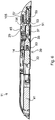
- the transmission screw 55 is in threaded engagement with a slide 57, which is mounted on the base body 13 in a slidable manner.
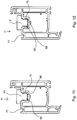
- each guide slot 66 spaced from one another along the longitudinal axis L are formed, in which slide blocks in the form of control pins 67 fixedly arranged on the base body 13 are received.
- Each guide slot 66 has respective holding sections 69 at its ends which extend along the longitudinal axis L.
- a control section 71 running at an angle to the longitudinal axis L is located between the holding sections 69.
- the two clamping rails 65 are adjacent to one another. If proceeding from this State the drive pins 59 by moving the slide 57 accordingly ( Fig. 8 ) are moved to the left, the clamping rails 65 are also moved to the left and - due to the interaction of the guide links 66 and the control pin 67 - are also moved apart until they reach the Fig. 10 have reached the fixing position shown. In this state, the seat of the control pin 67 in the holding sections 69 is self-locking, that is, no further effort is required by the slide 57 to hold the clamping rails 65 in the position moved apart. The screw engagement between the transmission screw 55 and the slide 57 can also contribute to the self-locking effect.
- the movable apart clamping rails 65 serve the movable apart clamping rails 65 for releasably fixing the base body 13 in a fitting groove 75 of a frame profile 77.
- the clamping rails 65 as in Fig. 11 are moved together, the base body 13 can in principle be inserted into the fitting groove 75 at any position. If, however, the clamping rails 65 as in Fig. 12 are moved apart, the base body 13 is fixed in a clamping manner in the fitting groove 75.
- the clamping rails 65 ' are additionally provided with latching elements 90, which engage behind respective lugs 91 of the fitting groove 75' and thus improve the holding effect.
- the motor 33 ( Figures 5 to 8 ) can be coupled to the movable clamping rails 65 via the transmission screw 55 and the slide 57 so as to be effective for driving, the coupling also being releasable again. If one There is a drive effective coupling between the motor 33 and the clamping rails 65 or not, depends on whether the drive spindle 37 is as in Fig. 6 and 7th shown is so close to the transmission screw 55 that the outer profile 52 and the inner profile 53 are in engagement with each other, or whether the outer profile 52 and the inner profile 53 as in Fig. 8 shown spaced apart and therefore disengaged.
- An operating section 100 which can be easily grasped by a user is formed at one end region of the base plate 14.
- a compression spring 105 which engages the actuation section 100 and is supported on the base body 13
- the drive unit 39 is moved in the direction of FIG Fig. 8 non-engagement position shown biased.
- the drive unit 39 is pretensioned in the opposite direction by a spiral spring 107, so that the drive unit 39 is mounted on the base body 13 in a floating manner.
- a user positions the base body 13 in a fitting groove 75 and then presses the actuating section 100 manually against the force of the compression spring 105 in the direction of the transmission screw 55 until the outer profile 52, as in FIG Fig. 6 shown engages in the inner profile 53.
- the motor 33 is then activated in such a way that, while the drive spindle 37 and the transmission screw 55 are turned, the slide 57 moves towards the drive spindle 37 (in Fig. 6 to the left), the clamping rails 65 being moved apart as explained above.
- the displacement unit 29 is displaced relative to the drive unit 39 due to the rotation of the drive spindle 37, but this is irrelevant for the assembly.
- the compression spring 105 presses the drive unit 39 to the left in the image until the in Fig. 8
- the state shown of the closure 11 is reached. In this state, the compression spring 105 is relaxed and the outer profile 52 is decoupled from the inner profile 53.
- the shutter 11 is now in a mounted normal state, in which the motor 33 only controls the position of the displacement unit 29, but has no influence on the position of the clamping rails 65. In this way, it is possible, after a corresponding positioning on the associated frame profile 77 ( Fig. 11 ) to fix automatically by activating the motor 33 for the first time.
- the lock 11 can also be released again from the frame profile 77 by activating the motor 11 accordingly.
- the actuating section 100 is again manually pressed against the force of the compression spring 105 in the direction of the transmission screw 55 until the outer profile 52 engages in the inner profile 53 as in FIG Fig. 7 shown comes.
- the slide 57 can be moved to the right, whereby the clamping rails 65 move towards one another again and the fastening of the lock 11 in the fitting groove 75 is released.
Claims (15)
- Fermeture (11) pour une fenêtre, une porte ou similaire, la fenêtre, la porte ou similaire comprenant un cadre et un battant mobile par rapport au cadre, la fermeture (11) comprenant :un corps de base (13) réalisé pour être fixé au cadre ou au battant, etun élément de fermeture (15) monté sur le corps de base (13), qui définit un logement de retenue (19) pour un élément de verrouillage fixé au battant ou au cadre et qui est mobile entre une position de libération libérant l'élément de verrouillage dans une direction d'ouverture (R) du battant et une position de blocage bloquant l'élément de verrouillage dans la direction d'ouverture, dans laquellelorsque la fermeture (11) est montée, l'élément de fermeture (15) peut être déplacé automatiquement de la position de libération en direction de la position de blocage par un mouvement de fermeture du battant et, dans au moins une position d'arrêt située entre la position de libération et la position de blocage et bloquant déjà l'élément de verrouillage dans la direction d'ouverture (R), peut être enclenché avec le corps de base (13) de telle sorte qu'un mouvement de l'élément de fermeture (15) en direction de la position de libération est empêché, mais qu'un mouvement de l'élément de fermeture (15) en direction de la position de blocage est autorisé, etla fermeture (11) comprend un moteur (33) disposé sur le corps de base (13) et prévu pour solliciter, lors d'une activation, directement ou indirectement l'élément de fermeture (15) se trouvant dans sa position d'arrêt de telle sorte qu'il se déplace jusque dans la position de blocage,caractérisée en ce quele corps de base (13) est réalisé pour être fixé dans une rainure à ferrure du cadre ou du battant, en ce quele moteur (33) est réalisé sous forme de moteur électrique, un accumulateur d'énergie électrique (41) destiné à fournir de l'énergie au moteur électrique (33) étant disposé sur le corps de base (13), et en ce que le corps de base (13) comporte une partie de boîtier qui entoure au moins partiellement le moteur (33) et/ou l'accumulateur d'énergie électrique (41).
- Fermeture selon la revendication 1,
caractérisée en ce que
un cliquet d'arrêt (27) est monté de façon mobile, en particulier en pivotement, sur le corps de base (13), qui, en vue d'enclencher l'élément de fermeture (15) avec le corps de base, s'engage dans un logement d'enclenchement de l'élément de fermeture (15) ou engage par l'arrière un talon d'enclenchement (21) de l'élément de fermeture (15). - Fermeture selon la revendication 2,
caractérisée en ce que
le cliquet d'arrêt (27) est monté sur une unité de translation (29) qui est montée sur le corps de base (13) de manière à pouvoir être translatée entre une position d'enclenchement dans laquelle un engagement du cliquet d'arrêt (27) dans le logement d'enclenchement ou un engagement par l'arrière du talon d'enclenchement (21) est autorisé, et une position de détachement dans laquelle le cliquet d'arrêt (27) est retiré du logement d'enclenchement ou du talon d'enclenchement (21), le moteur (33) étant couplé en entraînement à l'unité de translation (29). - Fermeture selon la revendication 3,
caractérisée en ce que
le moteur (33) comprend un arbre de sortie (50) pouvant être entraîné en rotation, et
un entraînement par broche (49) est prévu pour convertir le mouvement de rotation de l'arbre de sortie (50) en un mouvement de translation de l'unité de translation (29). - Fermeture selon la revendication 3 ou 4,
caractérisée en ce que
le cliquet d'arrêt (27) est précontraint par rapport à l'unité de translation (29) par un dispositif à ressort (31) en direction de l'élément de fermeture (15). - Fermeture selon l'une des revendications 3 à 5,
caractérisée en ce que
l'unité de translation (29) peut être translatée au-delà de la position d'arrêt en direction de l'élément de fermeture (15), afin de pousser l'élément de fermeture (15) jusque dans la position de blocage au moyen d'une sollicitation par le cliquet d'arrêt (27). - Fermeture selon l'une des revendications précédentes,
caractérisée en ce que
l'élément de fermeture (15) est précontraint par un ressort (23) en direction de la position de libération, et/ou en ce que
le moteur (33) sollicite l'élément de fermeture (15) par l'intermédiaire d'un dispositif de transmission autobloquant (49). - Fermeture selon l'une des revendications précédentes,
caractérisée en ce que
seul l'accumulateur d'énergie (41) disposé sur le corps de base (13) est prévu pour l'alimentation en énergie du moteur électrique (33). - Fermeture selon l'une des revendications précédentes,
caractérisée par
une unité de réception de signaux, de préférence sans fil, associée au moteur (33), au moyen de laquelle le moteur (33) peut être commandé à distance, et/ou par
une unité d'émission de signaux, de préférence sans fil, associée au moteur (33) pour transmettre les informations d'état relatives au moteur (33) à une autre fermeture (11) ou à un dispositif de commande externe. - Fermeture selon l'une des revendications précédentes,
caractérisée en ce que
le moteur (33) peut être couplé en entraînement à au moins un élément de fixation (65) monté de façon mobile sur le corps de base (13), et, lors du montage de la fermeture (11), il est apte à déplacer l'élément de fixation (65) jusque dans une position de fixation dans laquelle le corps de base (13) est fixé au cadre ou au battant. - Fermeture selon la revendication 10,
caractérisée en ce que
ledit au moins un élément de fixation (65) est réalisé pour coincer et/ou caler le corps de base (13) dans une rainure à ferrure (75, 75') du cadre ou du battant, et en particulier
le moteur (33) peut être couplé en entraînement à deux éléments de fixation (65) qui peuvent être écartés l'un de l'autre pour coincer le corps de base (13) dans une rainure à ferrure (75, 75') du cadre ou du battant, et, de préférence
lesdits deux éléments de fixation (65) sont réalisés sous forme de rails de coincement allongés s'étendant parallèlement l'un à l'autre qui peuvent être écartés l'un de l'autre transversalement à l'axe longitudinal (L) des rails. - Fermeture selon la revendication 11,
caractérisée en ce que
les rails de coincement (65) peuvent être écartés l'un de l'autre par un élément de transmission (57) mobile en translation en direction de l'axe longitudinal (L) des rails et susceptible d'être couplé en entraînement au moteur (33), un moyen de conversion (66, 67) étant prévu pour convertir la translation longitudinale de l'élément de transmission (57) en une translation transversale des rails de coincement (65), et
le moyen de conversion comprend de préférence une commande à coulisses (66, 67), et en particulier
la commande à coulisses comprend au moins deux coulisses de guidage (66) ayant chacune des portions de retenue autobloquantes (69) pour immobiliser les rails de coincement (65) dans la position écartée. - Fermeture selon l'une des revendications 10 à 12,
caractérisée en ce que
le couplage en entraînement du moteur (33) audit au moins un élément de fixation (65) est amovible. - Fermeture selon la revendication 13,
caractérisée en ce que
une unité d'entraînement (39) comprenant le moteur (33) est montée de façon mobile en translation sur le corps de base (13) de telle sorte qu'un élément d'entraînement (52) de l'unité d'entraînement (39) puisse être désengagé d'un élément de transmission (55) afin de défaire le couplage en entraînement, et, de préférence
l'unité d'entraînement (39) est précontrainte par un dispositif à ressort (105) vers une position non engagée dans laquelle l'élément d'entraînement (52) et l'élément de transmission (55) sont désengagés. - Fermeture selon l'une des revendications précédentes,
caractérisée en ce que
la fermeture est réalisée sous forme de pièce de ferrure, en particulier sous forme de pièce de ferrure pour une fenêtre de bâtiment, une porte de bâtiment ou similaire.
Priority Applications (2)
| Application Number | Priority Date | Filing Date | Title |
|---|---|---|---|
| PL19155693T PL3502386T3 (pl) | 2015-07-28 | 2016-07-04 | Zamknięcie do okna, drzwi lub tym podobnych |
| EP19155693.5A EP3502386B1 (fr) | 2015-07-28 | 2016-07-04 | Fermeture pour une fenêtre, une porte ou analogue |
Applications Claiming Priority (2)
| Application Number | Priority Date | Filing Date | Title |
|---|---|---|---|
| DE102015112256.1A DE102015112256A1 (de) | 2015-07-28 | 2015-07-28 | Verschluss für ein Fenster, eine Tür oder dergleichen |
| PCT/EP2016/065684 WO2017016809A1 (fr) | 2015-07-28 | 2016-07-04 | Fermeture de fenêtre, de porte ou similaire |
Related Child Applications (2)
| Application Number | Title | Priority Date | Filing Date |
|---|---|---|---|
| EP19155693.5A Division EP3502386B1 (fr) | 2015-07-28 | 2016-07-04 | Fermeture pour une fenêtre, une porte ou analogue |
| EP19155693.5A Division-Into EP3502386B1 (fr) | 2015-07-28 | 2016-07-04 | Fermeture pour une fenêtre, une porte ou analogue |
Publications (2)
| Publication Number | Publication Date |
|---|---|
| EP3307973A1 EP3307973A1 (fr) | 2018-04-18 |
| EP3307973B1 true EP3307973B1 (fr) | 2020-09-02 |
Family
ID=56360394
Family Applications (2)
| Application Number | Title | Priority Date | Filing Date |
|---|---|---|---|
| EP16735640.1A Active EP3307973B1 (fr) | 2015-07-28 | 2016-07-04 | Fermeture de fenêtre, de porte ou similaire |
| EP19155693.5A Active EP3502386B1 (fr) | 2015-07-28 | 2016-07-04 | Fermeture pour une fenêtre, une porte ou analogue |
Family Applications After (1)
| Application Number | Title | Priority Date | Filing Date |
|---|---|---|---|
| EP19155693.5A Active EP3502386B1 (fr) | 2015-07-28 | 2016-07-04 | Fermeture pour une fenêtre, une porte ou analogue |
Country Status (5)
| Country | Link |
|---|---|
| EP (2) | EP3307973B1 (fr) |
| CN (1) | CN107923201B (fr) |
| DE (1) | DE102015112256A1 (fr) |
| PL (1) | PL3502386T3 (fr) |
| WO (1) | WO2017016809A1 (fr) |
Families Citing this family (5)
| Publication number | Priority date | Publication date | Assignee | Title |
|---|---|---|---|---|
| DE102019117867A1 (de) * | 2019-07-02 | 2021-01-07 | Maco Technologie Gmbh | Verschluss mit einem verstärkten gehäuse für ein fenster, eine tür oder dergleichen |
| DE102019118550A1 (de) | 2019-07-09 | 2021-01-14 | Maco Technologie Gmbh | Verschluss |
| DE102019118535A1 (de) * | 2019-07-09 | 2021-01-14 | Maco Technologie Gmbh | Verschluss für ein fenster, eine tür oder dergleichen |
| DE102019118537A1 (de) * | 2019-07-09 | 2021-01-14 | Maco Technologie Gmbh | Verschlusssystem für ein fenster, eine tür oder dergleichen |
| DE202019106374U1 (de) | 2019-11-15 | 2019-12-20 | Siegenia-Aubi Kg | Tür- oder Fenstersystem |
Citations (12)
| Publication number | Priority date | Publication date | Assignee | Title |
|---|---|---|---|---|
| DE1459151A1 (de) | 1962-02-03 | 1968-12-12 | Jaeger Kg Frank | UEber ein Verschlussgetriebe fuer Fluegel von Fenstern,Tueren od. dgl. zu schaltendeFeststellvorrichtung zur OEffnungsbegrenzung von Dreh-Kipp-Fluegeln |
| US4633687A (en) * | 1985-01-22 | 1987-01-06 | Ni Industries, Inc. | Drive mechanism for key operated electronic lock |
| DE19904663A1 (de) | 1999-02-04 | 2000-08-17 | Bosch Gmbh Robert | Kraftfahrzeug-Türschloß o. dgl. mit elektrischer Schließhilfe und Öffnungshilfe |
| DE19944051A1 (de) | 1999-09-14 | 2001-03-15 | Wilke Heinrich Hewi Gmbh | Verriegelungsvorrichtung |
| US20030024288A1 (en) * | 2001-07-31 | 2003-02-06 | Gokcebay Asil T. | Locker lock with adjustable bolt |
| DE102006009835A1 (de) | 2005-03-04 | 2006-09-07 | Marquardt Gmbh | Elektrisches Türschloß |
| EP1557511B1 (fr) | 2004-01-21 | 2007-06-27 | Ferco International Ferrures et Serrures de Bâtiment Société par actions simplifiée | Ferrure notamment de verrouillage |
| DE102006019515A1 (de) | 2006-04-13 | 2007-10-18 | Rahrbach Gmbh | Mehrstufiger Türverschluss |
| EP1972743A2 (fr) | 2007-03-23 | 2008-09-24 | Mayer & Co. | Elément de fermeture |
| DE102009035737A1 (de) | 2009-08-01 | 2011-02-03 | Assa Abloy Sicherheitstechnik Gmbh | Zuziehvorrichtung für eine Tür |
| EP2806090A2 (fr) | 2013-05-24 | 2014-11-26 | Siegenia-Aubi Kg | Dispositif pour le verrouillage ou le déverrouillage d'un ouvrant coulissant |
| DE102013108224A1 (de) | 2013-07-31 | 2015-02-05 | Kiekert Aktiengesellschaft | Kraftfahrzeugtür |
Family Cites Families (6)
| Publication number | Priority date | Publication date | Assignee | Title |
|---|---|---|---|---|
| GB2379952A (en) * | 2001-09-22 | 2003-03-26 | Brunel Components Ltd | Automatic catch for a door or window |
| CN1325743C (zh) * | 2004-01-16 | 2007-07-11 | 董祥义 | 一种用于平开窗的电动手动两用上锁机构 |
| DE102006015870A1 (de) * | 2006-04-05 | 2007-10-11 | GM Global Technology Operations, Inc., Detroit | Haubenschloss |
| HK1150349A2 (en) | 2010-04-16 | 2011-12-09 | Austin Hughes Electronics Ltd | Door locking system |
| US8474883B2 (en) * | 2010-08-03 | 2013-07-02 | GM Global Technology Operations LLC | Latching mechanism |
| US9322194B2 (en) | 2013-03-15 | 2016-04-26 | August Home, Inc. | Intelligent door lock system |
-
2015
- 2015-07-28 DE DE102015112256.1A patent/DE102015112256A1/de active Pending
-
2016
- 2016-07-04 EP EP16735640.1A patent/EP3307973B1/fr active Active
- 2016-07-04 EP EP19155693.5A patent/EP3502386B1/fr active Active
- 2016-07-04 WO PCT/EP2016/065684 patent/WO2017016809A1/fr unknown
- 2016-07-04 CN CN201680044003.2A patent/CN107923201B/zh active Active
- 2016-07-04 PL PL19155693T patent/PL3502386T3/pl unknown
Patent Citations (12)
| Publication number | Priority date | Publication date | Assignee | Title |
|---|---|---|---|---|
| DE1459151A1 (de) | 1962-02-03 | 1968-12-12 | Jaeger Kg Frank | UEber ein Verschlussgetriebe fuer Fluegel von Fenstern,Tueren od. dgl. zu schaltendeFeststellvorrichtung zur OEffnungsbegrenzung von Dreh-Kipp-Fluegeln |
| US4633687A (en) * | 1985-01-22 | 1987-01-06 | Ni Industries, Inc. | Drive mechanism for key operated electronic lock |
| DE19904663A1 (de) | 1999-02-04 | 2000-08-17 | Bosch Gmbh Robert | Kraftfahrzeug-Türschloß o. dgl. mit elektrischer Schließhilfe und Öffnungshilfe |
| DE19944051A1 (de) | 1999-09-14 | 2001-03-15 | Wilke Heinrich Hewi Gmbh | Verriegelungsvorrichtung |
| US20030024288A1 (en) * | 2001-07-31 | 2003-02-06 | Gokcebay Asil T. | Locker lock with adjustable bolt |
| EP1557511B1 (fr) | 2004-01-21 | 2007-06-27 | Ferco International Ferrures et Serrures de Bâtiment Société par actions simplifiée | Ferrure notamment de verrouillage |
| DE102006009835A1 (de) | 2005-03-04 | 2006-09-07 | Marquardt Gmbh | Elektrisches Türschloß |
| DE102006019515A1 (de) | 2006-04-13 | 2007-10-18 | Rahrbach Gmbh | Mehrstufiger Türverschluss |
| EP1972743A2 (fr) | 2007-03-23 | 2008-09-24 | Mayer & Co. | Elément de fermeture |
| DE102009035737A1 (de) | 2009-08-01 | 2011-02-03 | Assa Abloy Sicherheitstechnik Gmbh | Zuziehvorrichtung für eine Tür |
| EP2806090A2 (fr) | 2013-05-24 | 2014-11-26 | Siegenia-Aubi Kg | Dispositif pour le verrouillage ou le déverrouillage d'un ouvrant coulissant |
| DE102013108224A1 (de) | 2013-07-31 | 2015-02-05 | Kiekert Aktiengesellschaft | Kraftfahrzeugtür |
Also Published As
| Publication number | Publication date |
|---|---|
| CN107923201A (zh) | 2018-04-17 |
| DE102015112256A1 (de) | 2017-02-02 |
| EP3502386A1 (fr) | 2019-06-26 |
| PL3502386T3 (pl) | 2021-08-02 |
| WO2017016809A1 (fr) | 2017-02-02 |
| EP3502386B1 (fr) | 2020-12-30 |
| CN107923201B (zh) | 2019-12-13 |
| EP3307973A1 (fr) | 2018-04-18 |
Similar Documents
| Publication | Publication Date | Title |
|---|---|---|
| EP3307973B1 (fr) | Fermeture de fenêtre, de porte ou similaire | |
| EP3058154B1 (fr) | Poignée de porte | |
| EP3309333A1 (fr) | Système comprenant un châssis dormant destiné à loger un cadre de vantail | |
| EP2692969B1 (fr) | Engrenage d'un dispositif de verrouillage à crémone, dispositif de verrouillage avec un tel engrenage ainsi que fenêtre, porte ou analogue avec un tel dispositif de verrouillage à crémone | |
| EP3307969B1 (fr) | Fermeture pour fenêtre, porte ou similaire | |
| EP2626491B1 (fr) | Agencement de ferrure | |
| EP1921233B1 (fr) | Entraînement de commande pouvant être rééquipé pour une porte pivotante ou analogue | |
| DE102004015147A1 (de) | Antriebseinrichtung | |
| EP3034719B1 (fr) | Dispositif d'actionnement d'un mecanisme de verrouillage d'une porte ou d'une fenetre | |
| EP3371397B1 (fr) | Ensemble ferrure | |
| EP3963158B1 (fr) | Fermeture pour fenêtre, porte ou analogue | |
| DE60121495T2 (de) | Verriegelungsvorrichtung | |
| DE102012200640A1 (de) | Antriebsvorrichtung für eine gemeinsame Betätigung eines Zentralverschlusses und des Flügels eines Fensters oder einer Türe | |
| EP3847328B1 (fr) | Unité d'entraînement pour des applications en automobile | |
| EP3662123B1 (fr) | Serrure motorisée | |
| DE202011002661U1 (de) | Sicherheitsschloss | |
| EP1493892B1 (fr) | Dispositiv de verrouillage pour une fenêtre ou un volet | |
| EP1816291A2 (fr) | Dispositif d'entraînement pour un vantail pouvant être encliqueté dans un cadre de fenêtre | |
| EP3688257A1 (fr) | Serrure de véhicule automobile | |
| EP2620572B1 (fr) | Dispositif de verrouillage pour le blocage d'un mouvement d'un battant par rapport à un cadre | |
| DE102016122551A1 (de) | Flügelrahmen eines Fensters oder einer Tür | |
| EP2320013B1 (fr) | Armature dotée d'une transmission de renvoi | |
| DE10337593B4 (de) | Tor, insbesondere für Garagen | |
| EP0703332A1 (fr) | Poignée de manoeuvre | |
| DE102004010612A1 (de) | Kraftfahrzeugschloß |
Legal Events
| Date | Code | Title | Description |
|---|---|---|---|
| STAA | Information on the status of an ep patent application or granted ep patent |
Free format text: STATUS: THE INTERNATIONAL PUBLICATION HAS BEEN MADE |
|
| PUAI | Public reference made under article 153(3) epc to a published international application that has entered the european phase |
Free format text: ORIGINAL CODE: 0009012 |
|
| STAA | Information on the status of an ep patent application or granted ep patent |
Free format text: STATUS: REQUEST FOR EXAMINATION WAS MADE |
|
| 17P | Request for examination filed |
Effective date: 20180115 |
|
| AK | Designated contracting states |
Kind code of ref document: A1 Designated state(s): AL AT BE BG CH CY CZ DE DK EE ES FI FR GB GR HR HU IE IS IT LI LT LU LV MC MK MT NL NO PL PT RO RS SE SI SK SM TR |
|
| AX | Request for extension of the european patent |
Extension state: BA ME |
|
| DAV | Request for validation of the european patent (deleted) | ||
| DAX | Request for extension of the european patent (deleted) | ||
| STAA | Information on the status of an ep patent application or granted ep patent |
Free format text: STATUS: EXAMINATION IS IN PROGRESS |
|
| 17Q | First examination report despatched |
Effective date: 20181221 |
|
| GRAP | Despatch of communication of intention to grant a patent |
Free format text: ORIGINAL CODE: EPIDOSNIGR1 |
|
| STAA | Information on the status of an ep patent application or granted ep patent |
Free format text: STATUS: GRANT OF PATENT IS INTENDED |
|
| INTG | Intention to grant announced |
Effective date: 20200324 |
|
| GRAS | Grant fee paid |
Free format text: ORIGINAL CODE: EPIDOSNIGR3 |
|
| GRAA | (expected) grant |
Free format text: ORIGINAL CODE: 0009210 |
|
| STAA | Information on the status of an ep patent application or granted ep patent |
Free format text: STATUS: THE PATENT HAS BEEN GRANTED |
|
| AK | Designated contracting states |
Kind code of ref document: B1 Designated state(s): AL AT BE BG CH CY CZ DE DK EE ES FI FR GB GR HR HU IE IS IT LI LT LU LV MC MK MT NL NO PL PT RO RS SE SI SK SM TR |
|
| REG | Reference to a national code |
Ref country code: GB Ref legal event code: FG4D Free format text: NOT ENGLISH |
|
| REG | Reference to a national code |
Ref country code: AT Ref legal event code: REF Ref document number: 1308979 Country of ref document: AT Kind code of ref document: T Effective date: 20200915 Ref country code: CH Ref legal event code: EP |
|
| REG | Reference to a national code |
Ref country code: DE Ref legal event code: R096 Ref document number: 502016011036 Country of ref document: DE |
|
| REG | Reference to a national code |
Ref country code: IE Ref legal event code: FG4D Free format text: LANGUAGE OF EP DOCUMENT: GERMAN |
|
| REG | Reference to a national code |
Ref country code: NL Ref legal event code: FP |
|
| REG | Reference to a national code |
Ref country code: LT Ref legal event code: MG4D |
|
| PG25 | Lapsed in a contracting state [announced via postgrant information from national office to epo] |
Ref country code: BG Free format text: LAPSE BECAUSE OF FAILURE TO SUBMIT A TRANSLATION OF THE DESCRIPTION OR TO PAY THE FEE WITHIN THE PRESCRIBED TIME-LIMIT Effective date: 20201202 Ref country code: LT Free format text: LAPSE BECAUSE OF FAILURE TO SUBMIT A TRANSLATION OF THE DESCRIPTION OR TO PAY THE FEE WITHIN THE PRESCRIBED TIME-LIMIT Effective date: 20200902 Ref country code: FI Free format text: LAPSE BECAUSE OF FAILURE TO SUBMIT A TRANSLATION OF THE DESCRIPTION OR TO PAY THE FEE WITHIN THE PRESCRIBED TIME-LIMIT Effective date: 20200902 Ref country code: SE Free format text: LAPSE BECAUSE OF FAILURE TO SUBMIT A TRANSLATION OF THE DESCRIPTION OR TO PAY THE FEE WITHIN THE PRESCRIBED TIME-LIMIT Effective date: 20200902 Ref country code: HR Free format text: LAPSE BECAUSE OF FAILURE TO SUBMIT A TRANSLATION OF THE DESCRIPTION OR TO PAY THE FEE WITHIN THE PRESCRIBED TIME-LIMIT Effective date: 20200902 Ref country code: GR Free format text: LAPSE BECAUSE OF FAILURE TO SUBMIT A TRANSLATION OF THE DESCRIPTION OR TO PAY THE FEE WITHIN THE PRESCRIBED TIME-LIMIT Effective date: 20201203 Ref country code: NO Free format text: LAPSE BECAUSE OF FAILURE TO SUBMIT A TRANSLATION OF THE DESCRIPTION OR TO PAY THE FEE WITHIN THE PRESCRIBED TIME-LIMIT Effective date: 20201202 |
|
| PG25 | Lapsed in a contracting state [announced via postgrant information from national office to epo] |
Ref country code: RS Free format text: LAPSE BECAUSE OF FAILURE TO SUBMIT A TRANSLATION OF THE DESCRIPTION OR TO PAY THE FEE WITHIN THE PRESCRIBED TIME-LIMIT Effective date: 20200902 Ref country code: LV Free format text: LAPSE BECAUSE OF FAILURE TO SUBMIT A TRANSLATION OF THE DESCRIPTION OR TO PAY THE FEE WITHIN THE PRESCRIBED TIME-LIMIT Effective date: 20200902 |
|
| PG25 | Lapsed in a contracting state [announced via postgrant information from national office to epo] |
Ref country code: EE Free format text: LAPSE BECAUSE OF FAILURE TO SUBMIT A TRANSLATION OF THE DESCRIPTION OR TO PAY THE FEE WITHIN THE PRESCRIBED TIME-LIMIT Effective date: 20200902 Ref country code: PT Free format text: LAPSE BECAUSE OF FAILURE TO SUBMIT A TRANSLATION OF THE DESCRIPTION OR TO PAY THE FEE WITHIN THE PRESCRIBED TIME-LIMIT Effective date: 20210104 Ref country code: RO Free format text: LAPSE BECAUSE OF FAILURE TO SUBMIT A TRANSLATION OF THE DESCRIPTION OR TO PAY THE FEE WITHIN THE PRESCRIBED TIME-LIMIT Effective date: 20200902 Ref country code: SM Free format text: LAPSE BECAUSE OF FAILURE TO SUBMIT A TRANSLATION OF THE DESCRIPTION OR TO PAY THE FEE WITHIN THE PRESCRIBED TIME-LIMIT Effective date: 20200902 Ref country code: CZ Free format text: LAPSE BECAUSE OF FAILURE TO SUBMIT A TRANSLATION OF THE DESCRIPTION OR TO PAY THE FEE WITHIN THE PRESCRIBED TIME-LIMIT Effective date: 20200902 |
|
| REG | Reference to a national code |
Ref country code: DE Ref legal event code: R026 Ref document number: 502016011036 Country of ref document: DE |
|
| PG25 | Lapsed in a contracting state [announced via postgrant information from national office to epo] |
Ref country code: IS Free format text: LAPSE BECAUSE OF FAILURE TO SUBMIT A TRANSLATION OF THE DESCRIPTION OR TO PAY THE FEE WITHIN THE PRESCRIBED TIME-LIMIT Effective date: 20210102 Ref country code: ES Free format text: LAPSE BECAUSE OF FAILURE TO SUBMIT A TRANSLATION OF THE DESCRIPTION OR TO PAY THE FEE WITHIN THE PRESCRIBED TIME-LIMIT Effective date: 20200902 Ref country code: AL Free format text: LAPSE BECAUSE OF FAILURE TO SUBMIT A TRANSLATION OF THE DESCRIPTION OR TO PAY THE FEE WITHIN THE PRESCRIBED TIME-LIMIT Effective date: 20200902 |
|
| PLBI | Opposition filed |
Free format text: ORIGINAL CODE: 0009260 |
|
| PLAX | Notice of opposition and request to file observation + time limit sent |
Free format text: ORIGINAL CODE: EPIDOSNOBS2 |
|
| PG25 | Lapsed in a contracting state [announced via postgrant information from national office to epo] |
Ref country code: SK Free format text: LAPSE BECAUSE OF FAILURE TO SUBMIT A TRANSLATION OF THE DESCRIPTION OR TO PAY THE FEE WITHIN THE PRESCRIBED TIME-LIMIT Effective date: 20200902 |
|
| 26 | Opposition filed |
Opponent name: GEZE GMBH Effective date: 20210528 |
|
| PG25 | Lapsed in a contracting state [announced via postgrant information from national office to epo] |
Ref country code: SI Free format text: LAPSE BECAUSE OF FAILURE TO SUBMIT A TRANSLATION OF THE DESCRIPTION OR TO PAY THE FEE WITHIN THE PRESCRIBED TIME-LIMIT Effective date: 20200902 Ref country code: DK Free format text: LAPSE BECAUSE OF FAILURE TO SUBMIT A TRANSLATION OF THE DESCRIPTION OR TO PAY THE FEE WITHIN THE PRESCRIBED TIME-LIMIT Effective date: 20200902 |
|
| PLBB | Reply of patent proprietor to notice(s) of opposition received |
Free format text: ORIGINAL CODE: EPIDOSNOBS3 |
|
| REG | Reference to a national code |
Ref country code: CH Ref legal event code: PL |
|
| GBPC | Gb: european patent ceased through non-payment of renewal fee |
Effective date: 20210704 |
|
| PG25 | Lapsed in a contracting state [announced via postgrant information from national office to epo] |
Ref country code: MC Free format text: LAPSE BECAUSE OF FAILURE TO SUBMIT A TRANSLATION OF THE DESCRIPTION OR TO PAY THE FEE WITHIN THE PRESCRIBED TIME-LIMIT Effective date: 20200902 |
|
| REG | Reference to a national code |
Ref country code: BE Ref legal event code: MM Effective date: 20210731 |
|
| PG25 | Lapsed in a contracting state [announced via postgrant information from national office to epo] |
Ref country code: LI Free format text: LAPSE BECAUSE OF NON-PAYMENT OF DUE FEES Effective date: 20210731 Ref country code: GB Free format text: LAPSE BECAUSE OF NON-PAYMENT OF DUE FEES Effective date: 20210704 Ref country code: CH Free format text: LAPSE BECAUSE OF NON-PAYMENT OF DUE FEES Effective date: 20210731 |
|
| PG25 | Lapsed in a contracting state [announced via postgrant information from national office to epo] |
Ref country code: LU Free format text: LAPSE BECAUSE OF NON-PAYMENT OF DUE FEES Effective date: 20210704 |
|
| PG25 | Lapsed in a contracting state [announced via postgrant information from national office to epo] |
Ref country code: IE Free format text: LAPSE BECAUSE OF NON-PAYMENT OF DUE FEES Effective date: 20210704 Ref country code: BE Free format text: LAPSE BECAUSE OF NON-PAYMENT OF DUE FEES Effective date: 20210731 |
|
| REG | Reference to a national code |
Ref country code: AT Ref legal event code: MM01 Ref document number: 1308979 Country of ref document: AT Kind code of ref document: T Effective date: 20210704 |
|
| PG25 | Lapsed in a contracting state [announced via postgrant information from national office to epo] |
Ref country code: AT Free format text: LAPSE BECAUSE OF NON-PAYMENT OF DUE FEES Effective date: 20210704 |
|
| REG | Reference to a national code |
Ref country code: DE Ref legal event code: R100 Ref document number: 502016011036 Country of ref document: DE |
|
| PLBP | Opposition withdrawn |
Free format text: ORIGINAL CODE: 0009264 |
|
| PLBD | Termination of opposition procedure: decision despatched |
Free format text: ORIGINAL CODE: EPIDOSNOPC1 |
|
| PLBD | Termination of opposition procedure: decision despatched |
Free format text: ORIGINAL CODE: EPIDOSNOPC1 |
|
| PLBM | Termination of opposition procedure: date of legal effect published |
Free format text: ORIGINAL CODE: 0009276 |
|
| PG25 | Lapsed in a contracting state [announced via postgrant information from national office to epo] |
Ref country code: HU Free format text: LAPSE BECAUSE OF FAILURE TO SUBMIT A TRANSLATION OF THE DESCRIPTION OR TO PAY THE FEE WITHIN THE PRESCRIBED TIME-LIMIT; INVALID AB INITIO Effective date: 20160704 |
|
| 27C | Opposition proceedings terminated |
Effective date: 20230106 |
|
| PG25 | Lapsed in a contracting state [announced via postgrant information from national office to epo] |
Ref country code: CY Free format text: LAPSE BECAUSE OF FAILURE TO SUBMIT A TRANSLATION OF THE DESCRIPTION OR TO PAY THE FEE WITHIN THE PRESCRIBED TIME-LIMIT Effective date: 20200902 |
|
| PGFP | Annual fee paid to national office [announced via postgrant information from national office to epo] |
Ref country code: TR Payment date: 20230626 Year of fee payment: 8 Ref country code: PL Payment date: 20230622 Year of fee payment: 8 Ref country code: NL Payment date: 20230719 Year of fee payment: 8 |
|
| PGFP | Annual fee paid to national office [announced via postgrant information from national office to epo] |
Ref country code: IT Payment date: 20230724 Year of fee payment: 8 |
|
| PGFP | Annual fee paid to national office [announced via postgrant information from national office to epo] |
Ref country code: FR Payment date: 20230726 Year of fee payment: 8 Ref country code: DE Payment date: 20230719 Year of fee payment: 8 |
|
| PG25 | Lapsed in a contracting state [announced via postgrant information from national office to epo] |
Ref country code: MK Free format text: LAPSE BECAUSE OF FAILURE TO SUBMIT A TRANSLATION OF THE DESCRIPTION OR TO PAY THE FEE WITHIN THE PRESCRIBED TIME-LIMIT Effective date: 20200902 |