EP3307500B1 - Schneidsystem zum schneiden von obst oder gemüse in spiralförmige girlanden - Google Patents
Schneidsystem zum schneiden von obst oder gemüse in spiralförmige girlanden Download PDFInfo
- Publication number
- EP3307500B1 EP3307500B1 EP16728050.2A EP16728050A EP3307500B1 EP 3307500 B1 EP3307500 B1 EP 3307500B1 EP 16728050 A EP16728050 A EP 16728050A EP 3307500 B1 EP3307500 B1 EP 3307500B1
- Authority
- EP
- European Patent Office
- Prior art keywords
- cutting
- receiving space
- holding part
- cut
- inserts
- Prior art date
- Legal status (The legal status is an assumption and is not a legal conclusion. Google has not performed a legal analysis and makes no representation as to the accuracy of the status listed.)
- Revoked
Links
- 238000005520 cutting process Methods 0.000 title claims description 240
- 235000013311 vegetables Nutrition 0.000 title claims description 8
- 235000013399 edible fruits Nutrition 0.000 title claims description 6
- 235000013305 food Nutrition 0.000 claims description 46
- 238000003780 insertion Methods 0.000 claims description 3
- 230000037431 insertion Effects 0.000 claims description 3
- 239000000463 material Substances 0.000 description 20
- 240000008067 Cucumis sativus Species 0.000 description 3
- 244000000626 Daucus carota Species 0.000 description 3
- 235000002767 Daucus carota Nutrition 0.000 description 3
- 244000088415 Raphanus sativus Species 0.000 description 3
- 235000006140 Raphanus sativus var sativus Nutrition 0.000 description 3
- 235000009849 Cucumis sativus Nutrition 0.000 description 2
- 235000012149 noodles Nutrition 0.000 description 2
- 235000016068 Berberis vulgaris Nutrition 0.000 description 1
- 241000335053 Beta vulgaris Species 0.000 description 1
- 235000010799 Cucumis sativus var sativus Nutrition 0.000 description 1
- 241000219130 Cucurbita pepo subsp. pepo Species 0.000 description 1
- 235000003954 Cucurbita pepo var melopepo Nutrition 0.000 description 1
- 240000008415 Lactuca sativa Species 0.000 description 1
- 244000141359 Malus pumila Species 0.000 description 1
- 235000021016 apples Nutrition 0.000 description 1
- 230000000694 effects Effects 0.000 description 1
- 235000012054 meals Nutrition 0.000 description 1
- 239000002184 metal Substances 0.000 description 1
- 235000012045 salad Nutrition 0.000 description 1
Images


Classifications
-
- B—PERFORMING OPERATIONS; TRANSPORTING
- B26—HAND CUTTING TOOLS; CUTTING; SEVERING
- B26D—CUTTING; DETAILS COMMON TO MACHINES FOR PERFORATING, PUNCHING, CUTTING-OUT, STAMPING-OUT OR SEVERING
- B26D3/00—Cutting work characterised by the nature of the cut made; Apparatus therefor
- B26D3/10—Making cuts of other than simple rectilinear form
- B26D3/11—Making cuts of other than simple rectilinear form to obtain pieces of spiral or helical form
-
- B—PERFORMING OPERATIONS; TRANSPORTING
- B26—HAND CUTTING TOOLS; CUTTING; SEVERING
- B26D—CUTTING; DETAILS COMMON TO MACHINES FOR PERFORATING, PUNCHING, CUTTING-OUT, STAMPING-OUT OR SEVERING
- B26D3/00—Cutting work characterised by the nature of the cut made; Apparatus therefor
- B26D3/28—Splitting layers from work; Mutually separating layers by cutting
- B26D3/283—Household devices therefor
- B26D2003/287—Household devices therefor having a holder for the product to be cut
-
- B—PERFORMING OPERATIONS; TRANSPORTING
- B26—HAND CUTTING TOOLS; CUTTING; SEVERING
- B26D—CUTTING; DETAILS COMMON TO MACHINES FOR PERFORATING, PUNCHING, CUTTING-OUT, STAMPING-OUT OR SEVERING
- B26D3/00—Cutting work characterised by the nature of the cut made; Apparatus therefor
- B26D3/28—Splitting layers from work; Mutually separating layers by cutting
- B26D3/283—Household devices therefor
- B26D2003/288—Household devices therefor making several incisions and cutting cubes or the like, e.g. so-called "julienne-cutter"
Definitions
- the invention relates to a cutting system for cutting fruit or vegetables in spiral garlands.
- Out EP 2 218 561 B1 is a device for spiral cutting of fruit and hard vegetables, such as apples, radishes, carrots, beets, cucumbers, with at least one basic body designed as a cone, funnel, cone or the like, in the outer surface of which at least one cutting device formed from a cutting gap and knife is arranged, known.
- the device consists of two base bodies which are connected to one another on the bottom and are designed as cones, funnels, cones or the like, each of which has at least one cutting device, the cutting gaps of the device being of different widths.
- a disadvantage of this device is that only and only two different types of garlands can be cut.
- US 2008/0307980 A1 is known device that can cut fruits and roots and bulbous vegetables.
- the device is operated in such a way that the material to be cut is placed in a closed cutting blade housing and rotated by means of a hand crank, whereby the material to be cut is cut helically by a spring-loaded cutting blade.
- the disadvantage of this device is that it is very complex and bulky.
- the device only and exclusively allows the material to be cut to be cut in a single way into a single type of garland.
- a device which is suitable for chopping food into small pieces, but not for cutting fruit or vegetables into spiral garlands.
- the device has a first housing that has a handle and a second housing that is detachably attached to the first housing.
- a cutting element is mounted in the second housing, while a device for driving the cutting element is mounted in the first housing.
- the drive device is operatively connected to the cutting element and is actuated by a switch.
- the cutting element is designed as a frustoconical plastic hollow housing with metal cutting blades which are integrally molded into the housing. The material to be shredded is pressed against the outside of the rotating cutting element, as a result of which parts of the material to be shredded are continuously separated and reach an ejection opening through the interior of the cutting element.
- a cutting system of the type mentioned at the outset which is characterized in that the cutting system has a plurality of different cutting inserts and a holding part with a cutting insert receptacle and with a dispensing opening for dispensing the spiral-shaped garlands, each cutting insert having a, in particular conical, receiving space for Introducing food product in which the food product is rotatable and wherein one of the cutting inserts, in particular detachable again without tools, can optionally be fixed in the cutting insert receptacle.
- the invention has the very special advantage that foods to be chopped, such as carrots, radishes or cucumbers, can optionally be cut into different types of spiral garlands, which are particularly suitable for decorating a meal, such as a salad preparation.
- foods to be chopped such as carrots, radishes or cucumbers
- spiral garlands which are particularly suitable for decorating a meal, such as a salad preparation.
- the user only has to select one of several different cutting inserts and insert them into the holding part.
- the user thus has the possibility of cutting spiral garlands of different widths and / or thicknesses and / or selecting the cutting insert according to the size or the nature of the food item to be cut.
- the user can advantageously decide individually, for example, whether he wants to cut the food item into thin, thick, wide or narrow spiral garlands.
- the invention has the very special advantage that particularly brittle or sensitive foods, in which the garlands tend to break if they are cut too thin, can alternatively be cut into thicker spiral garlands. Conversely, foods that are unsuitable for cutting into thick spiral garlands can optionally be cut into thin spiral garlands.
- the cutting inserts can, in particular, what is described in detail below, be designed to be very space-saving and / or even stackable.
- the cutting system according to the invention can advantageously be designed to be very compact and easy to handle.
- the holding part can be designed to be held in one hand only when it is used, so that the user can rotate the material to be cut with the other hand relative to the cutting insert inserted into the cutting insert receptacle.
- the holding part can advantageously have a grip section.
- the holding part is circular cylindrical and / or elongated.
- the diameter of the holding part can advantageously be in the range from 5 cm to 9 cm, in particular in the range from 6 cm to 8 cm, or quite particularly 7.5 cm.
- a particularly ergonomic design is one in which the cutting insert receptacle and the dispensing opening are arranged at opposite ends of the holding part.
- the holding part can be tubular, one tube opening forming the dispensing opening, while the other tube opening forming the entrance to the cutting insert receptacle.
- each cutting insert has a, in particular conical, receiving space for introducing food, on the wall of which a cutting blade is arranged in each case.
- the wall of the receiving space preferably has an opening through which the spiral garland can emerge from the receiving space.
- the cutting blade is preferably arranged in such a way that, in the case of a rotational movement, similar to pencil sharpening, a spiral-shaped layer is separated from the rotating foodstuff all round.
- the cutting edge of the cutting blade can be arranged in such a way that it projects into the receiving space, the parallel distance of the cutting blade from the wall of the receiving space determining the thickness of the separated layer.
- the cutting inserts can differ in particular in terms of their shape and / or size and / or in terms of the thickness and / or width of the spiral garlands which can be cut with them and / or in terms of the number of spiral garlands which arise simultaneously during a cutting process.
- At least one of the cutting inserts in particular each of the cutting inserts, can be locked in place and / or with a bayonet connection in the cutting insert receptacle, in particular releasably without tools. It is preferably the same type of snap-in connection or bayonet connection that the holding plate also has, so that the cutting inserts can be fixed on the holding plate as well as on the holding part without the additional adapter being required.
- a device designed in this way has on the one hand the very particular advantage that the user can individually decide by simply selecting the direction of rotation whether he wants to cut the food item into thin or thick spiral garlands.
- this solution has the very special advantage that particularly brittle or sensitive foods, in which the garlands tend to break if they are cut too thinly, can alternatively and without having to be converted, be cut into thicker spiral garlands. Conversely, foods that are unsuitable for cutting into thick spiral garlands can optionally be cut into thin spiral garlands.
- Such a design makes it possible, in particular, to adapt the cutting thickness quickly and efficiently to the respective food.
- the cutting into spiral garlands with different layer thicknesses can be achieved, for example, by using a pendulum blade which has two cutting edges.
- a pendulum blade which has two cutting edges.
- one cutting edge is used for cutting into thin spiral garlands, while the other cutting edge is used for cutting into thick spiral garlands.
- the pendulum blade can be arranged, for example, in such a way that, with respect to the first cutting edge, a first distance to the wall of the receiving space is established when the food item rotates in the clockwise direction, while a second distance from the second cutting edge is established when the food item rotates counterclockwise Sets the recording space, wherein the first distance is different from the second distance.
- the cutting blades can be oriented parallel to one another and / or opposite to one another with respect to the alignment of the cutting edges.
- the pendulum blade is suspended in such a way that when the Food items automatically rotate the first cutting edge clockwise into the receiving space while the second cutting edge is being rotated out of the receiving space, and that, conversely, when the food items are rotated counterclockwise, the second cutting edge automatically turns into the receiving space while the first cutting edge moves out of the receiving space is turned out.
- the cutting insert has a pendulum blade with two cutting edges, one of which - in particular automatically - cuts into the food item depending on the direction of rotation of the food item to be comminuted.
- At least one of the cutting inserts is designed to separate a plurality of spiral garlands from a food item at the same time.
- vegetables can advantageously be cut into vegetable noodles, for example zucchini noodles.
- the cutting insert can in particular have a cutting device which divides the layer to be separated or the layer already separated into a plurality of strips which are parallel to one another.
- the cutting insert has a cutting blade which separates a layer from the material to be cut and a cutting device which has further cutting blades arranged perpendicular to the cutting blade. The further cutting blades can serve to divide the layer to be separated or the layer that has already been separated into several parallel strips.
- the cutting inserts can differ from one another in terms of different parameters, which makes it possible to cut differently shaped spiral garlands.
- one of the cutting inserts may have a different size than another of the cutting inserts.
- the receiving space of one of the cutting inserts has a different cone angle than the receiving space of another of the cutting inserts and / or that the receiving space of one of the cutting inserts has a different size than the receiving space of another of the cutting inserts.
- the receiving space of one of the cutting inserts has a different insertion depth than the receiving space of another of the cutting inserts and / or that the receiving space of one of the cutting inserts has a different width than the receiving space of another of the cutting inserts.
- the cutting system has a cutting material holder.
- the product holder is preferably designed to be connected to the food product to be cut in a rotationally fixed manner.
- the product holder For example, have a plurality of thorns that are pressed into the food.
- a cutter holder has the particular advantage that the user has better control of the cutter. This is particularly the case if the material to be cut is damp or has a small diameter or if it is difficult to grip by hand for other reasons.
- the product holder can advantageously have a diameter that is larger than the diameter of the receiving space of the cutting inserts to be used. In this way it is advantageously achieved that the user can exert a particularly large torque on the food to be cut due to the large lever. This is particularly the case when the food product itself has a small diameter.
- the material holder can advantageously be substantially disc-shaped, in particular circular disc-shaped.
- the spikes can be arranged so as to protrude from the circular disk.
- the material holder is designed as a cover for the dispensing opening.
- the material holder can be fixed on the holding part by means of a snap-in connection or by means of a bayonet connection, in particular detachable again without tools.
- the cutlery holder designed as a cover completely covers the dispensing opening when it is attached to the holding part.
- the holding part has an external thread in the area of the dispensing opening, which is intended to interact with an internal thread of the material holder that can be used as a lid.
- the holding part can alternatively have an external thread in the area of the cutting insert receptacle, which cooperates with an internal thread of the cutting insert in order to be able to fix the cutting insert in the cutting insert receptacle, in particular detachably without tools.
- the holding part has two identical openings which are designed in such a way that each of the openings can function either as a dispensing opening or as an opening for inserting a cutting insert.
- the holding part is the same in the area of the openings Has an external thread, so that it is possible to fix a cutting insert or the cutting material holder in the region of each of the openings.
- the holding part for fixing the cutting insert and / or the cutting material holder has an internal thread, while the cutting insert and / or cutting material holder have an external thread.
- a snap-in connection and / or a plug connection can alternatively or additionally also be provided.
- a food processing system which has a cutting system according to the invention and a stamp which can be inserted into the holding part, in particular in a form-fitting manner, instead of a cutting insert, and a cutting disc which can be fixed on the holding part, in particular detachably without tools.
- a food processing system has the particular advantage that it can be used either for cutting food in spiral garlands or as a grater.
- the cutting disc can be fixed in the area of the dispensing opening on the holding part, in particular releasably without tools.
- the cutting disk is preferably fixed to the dispensing opening in such a way that it completely covers the entire dispensing opening.
- the cutting disc can be fixed on the holding part, in particular in a rotationally fixed manner, for example by means of a latching connection or by means of a bayonet connection or a plug connection.
- the holding part can have an external thread which interacts with a union nut which has an internal thread, the cutting disk to be used in each case being clamped between the end face of the holding part and the union nut.
- recesses and projections can be present in the cutting disc and the holding part, which prevent the cutting disc from rotating relative to the holding part during the grater-like cutting process.
- the cutting disc can be fixed on the holding part by means of a latching connection or by means of a bayonet connection or a plug connection, which is constructed identically, such as a latching connection or a bayonet connection or a plug connection, by means of which a cutting insert and / or a material holder on the holding part is definable. In this way it is possible to quickly and efficiently replace the different components with each other.
- the punch can be inserted into the holding part through a receiving opening of the cutting insert receptacle and rotated in the holding part.
- the stamp has at least one driver element, which ensures that a rotational movement of the stamp inserted into the holding part is transmitted to the food item previously inserted into the holding part, which ultimately leads to a relative movement of the food item relative to the cutting disk non-rotatably connected to the holding part.
- the food to be grated can be rotated relative to the cutting disc and at the same time pressed against the cutting disc.
- the driving element can be designed, for example, as a projection or as a groove or a protruding tip.
- the driving element can be designed as a groove running radially through the center, in particular V-shaped in cross section. It is also possible for the stamp to have several, in particular also several different, driving elements.
- the food processing system has a number of different cutting disks, one of which can be fixed to the holding part in a working position.
- Such an embodiment has the advantage that the user can select and use the cutting disc suitable for the current application.
- the stamp can advantageously be designed as a storage container for several, in particular several different, cutting disks.
- Such an embodiment has the particular advantage that the risk of cutting discs being lost is reduced.
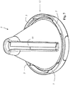
- FIG. 1 shows a detailed view of a cutting system according to the invention.
- the cutting system has a holding part 1, which provides a cutting insert receptacle 2.
- a cutting insert 3, such as that shown in FIGS Figures 3 to 8 is used.
- the holding part 1, which is constructed essentially in the shape of a circular cylinder, has an external thread 4 at the end, which can cooperate with an internal thread 5 of one of the cutting inserts 3.
- the user can freely decide which of several cutting inserts 3 he wants to use and thus has the possibility, for example, to cut spiral garlands of different widths and / or thicknesses and / or to select the cutting insert 3 according to the size or the nature of the food item to be cut.
- the holding part 1 has an outlet opening 6 (see in particular Figures 2 and 9 ) on, which can be closed by means of a cutting material holder 7, which is also designed as a lid for the dispensing opening.
- a cutting material holder 7 which is also designed as a lid for the dispensing opening.
- the holding part 1 also in the region of its dispensing opening 6 also has a bayonet-like external thread 4 which interacts with a bayonet-like internal thread 5 of the cutting material holder 7 when the cutting material holder 7 is placed on the output opening 6.
- the possibility of being able to fasten the product holder 7 to the discharge opening 6 has the very special advantage that the product holder 7 is directly on the holding part 1 can be stored and cannot be accidentally lost when storing the food shredding system.
- the cutlery holder 7 has vertically projecting mandrels 8, which are intended to be axially inserted into the foodstuff to be processed, so that the foodstuff can be rotated safely and reliably in the receiving space 9 of the cutting insert 3 with the aid of the cutlery holder 7.
- FIG. 3 shows a first embodiment of a cutting insert 3 in plan view in the axial direction.
- the cutting insert 3 has a conical receiving space 9, into which a food item, such as the tip of a cucumber, a carrot or a radish, can be inserted.
- a cutting blade 10 projects into the receiving space 9 and simultaneously cuts off several spiral garlands from the food product rotating in the receiving space 9.
- the simultaneous severing of several spiral garlands is achieved in that the cutting insert 3 has further cutting blades 11, which likewise protrude into the receiving space 9 and which are arranged perpendicular to the cutting blade 10.
- These further cutting blades 11 function as Julienne knives, which cut the layer to be separated by means of the cutting blade 10 into several strips.
- Figure 4 shows the already in Figure 9 shown cutting insert 3 in a side view. It can be seen that the cutting insert 3 has a grip section 12 on which the cutting insert 3 can be held for insertion into the cutting part receptacle 2 of the holding part 1. After inserting the cutting insert 3, it is preferably held in the holding part 1 in a rotationally fixed manner.
- the cutting insert 3 has a slot opening 13 in the region of the cutting blade 10 and the further cutting blades 11, through which the spiral-shaped garlands can emerge from the receiving space 9.
- Figure 5 shows the already in the Figures 3 and 4th shown cutting insert 3 in a perspective view.
- the cutting insert 3 has in the region of its grip section 12 a circumferential collar with a bayonet-like internal thread 5, which is intended to cooperate with one of the external threads 4 of the holding part 1.
- Figure 6 shows a second embodiment of a cutting insert 3, which differs from that in the Figures 3 to 5 illustrated embodiment differs in that the distance of the other cutting blades 11 from each other is greater, so that when using this cutting insert wider spiral garlands are formed.
- the in Figure 6 shown cutting insert constructed identically to that in the Figures 3 to 5 shown cutting insert 3, which ensures that the user can fix the different cutting inserts 3 on the holding part 1 in an identical manner and release them again.
- Figure 7 shows a third embodiment of a cutting insert 3, which has no further cutting blades 11 (Julienne knife).
- This third embodiment of a cutting insert 3 particularly wide spiral garlands are cut.
- Figure 8 shows a fourth embodiment of a cutting insert 3, which has a receiving space 9 with a smaller input diameter and a reduced cone angle.
- This cutting insert 3 can be used in particular to simultaneously cut off a large number of spiral garlands from foods with a thin diameter.
Landscapes
- Life Sciences & Earth Sciences (AREA)
- Forests & Forestry (AREA)
- Engineering & Computer Science (AREA)
- Mechanical Engineering (AREA)
- Food-Manufacturing Devices (AREA)
Description
- Die Erfindung betrifft ein Schneidsystem zum Schneiden von Obst oder Gemüse in spiralförmige Girlanden.
- Aus
EP 2 218 561 B1 ist eine Vorrichtung zum spiralförmigen Schneiden von Obst und hartem Gemüse, wie Äpfel, Rettich, Möhren, Rüben, Gurken, mit mindestens einem als Kegel, Trichter, Konus od. dgl. ausgebildeten Grundkörper, in dessen Mantelfläche wenigstens eine aus Schneidspalt und Messer gebildete Schneideinrichtung angeordnet ist, bekannt. Die Vorrichtung besteht aus zwei miteinander bodenseitig verbundenen, als Kegel, Trichter, Konus od. dgl. ausgebildeten Grundkörpern, welche jeweils mindestens eine Schneideinrichtung aufweisen, wobei die Schneidspalte der Vorrichtung unterschiedlich breit sind. - An dieser Vorrichtung ist nachteilig, dass lediglich und ausschließlich in zwei unterschiedliche Arten von Girlanden geschnitten werden kann.
- Aus
US 2008/0307980 A1 ist Vorrichtung bekannt, die Früchte und Wurzeln und Knollengemüse schneiden kann. Die Vorrichtung wird derart betrieben, daß das Schneidgut in einem geschlossenen Schneidklingengehäuse platziert und mittels einer Handkurbel gedreht wird, wodurch das Schneidgut von einer federbelasteten Schneidklinge schraubenförmig geschnitten wird. Nachteiliger Weise ist diese Vorrichtung sehr aufwändig aufgebaut und klobig. Außerdem erlaubt die Vorrichtung lediglich und ausschließlich, das Schneidgut auf eine einzige Art in eine einzige Art von Girlande zu schneiden. - Aus
US 5 680 997 A ist eine Vorrichtung bekannt, die zum Zerkleinern von Lebensmitteln in kleine Stücke, aber nicht zum Schneiden von Obst oder Gemüse in spiralförmige Girlanden geeignet ist. Die Vorrichtung weist ein erstes Gehäuse, das einen Griff hat, und ein zweites Gehäuse, das lösbar an dem ersten Gehäuse angebracht ist, auf. In dem zweiten Gehäuse ist ein Schneidelement montiert, während in dem ersten Gehäuse eine Vorrichtung zum Antreiben des Schneidelements angebracht ist. Die Antriebsvorrichtung ist mit dem Schneidelement wirkverbunden und wird durch einen Schalter betätigt. Das Schneidelement ist als ein kegelstumpfförmiges Kunststoffhohlgehäuse mit Metallschneidklingen, die einstückig in das Gehäuse eingeformt sind, ausgebildet. Das zu zerkleinernde Gut wird gegen die Außenseite des rotierenden Schneidelements gedrückt, wodurch Teile des zu zerkleinernden Gutes kontinuierlich abgetrennt werden und durch den Innenraum des Schneidelements hindurch zu einer Auswurföffnung gelangen. - Es ist daher die Aufgabe der vorliegenden Erfindung, ein Schneidsystem anzugeben, das das Schneiden unterschiedlichartiger spiralförmiger Girlanden erlaubt.
- Die Aufgabe wird durch ein Schneidsystem der eingangs genannten Art gelöst, das dadurch gekennzeichnet ist, dass das Schneidsystem mehrere unterschiedliche Schneideinsätze und ein Halteteil mit einer Schneideinsatzaufnahme und mit einer Ausgabeöffnung zum Ausgeben der spiralförmigen Girlanden aufweist, wobei jeder Schneideinsatz einen, insbesondere kegelförmigen, Aufnahmeraum zum Einführen von Lebensmittelgut aufweist, in dem das Lebensmittelgut rotierbar ist und wobei in der Schneideinsatzaufnahme wahlweise einer der Schneideinsätze, insbesondere werkzeugfrei wieder lösbar, festlegbar ist.
- Die Erfindung hat den ganz besonderen Vorteil, dass zu zerkleinernde Lebensmittel, wie beispielsweise Möhren, Rettich oder Gurken, wahlweise in unterschiedlichartige spiralförmige Girlanden geschnitten werden können, die insbesondere dazu geeignet sind, eine Mahlzeit, wie beispielsweise eine Salatzubereitung, zu verzieren. Dies ist dadurch erreicht, dass der Benutzer lediglich einen von mehreren, unterschiedlichartigen Schneideinsätzen auszuwählen und in das Halteteil einzusetzen braucht. Der Benutzer hat damit die Möglichkeit, unterschiedlich breite und/oder unterschiedlich dicke spiralförmige Girlanden zu schneiden und/oder den Schneideinsatz entsprechend der Größe oder der Beschaffenheit des zu schneidenden Lebensmittelgutes auszuwählen. In vorteilhafter Weise kann der Benutzer durch die Auswahl des Schneideinsatzes individuell beispielsweise entscheiden, ob er das Lebensmittelgut in dünne, dicke, breite oder schmale spiralförmige Girlanden schneiden will. Zum anderen hat die Erfindung den ganz besonderen Vorteil, dass besonders spröde oder empfindliche Lebensmittel, bei denen die Girlanden dazu neigen zu brechen, wenn sie zu dünn geschnitten werden, alternativ in dickere spiralförmige Girlanden geschnitten werden können. Umgekehrt können Lebensmittel, die für ein Schneiden in dicke spiralförmige Girlanden ungeeignet sind, wahlweise in dünne spiralförmige Girlanden geschnitten werden.
- Die Schneideinsätze können insbesondere, was weiter unten noch im Detail beschrieben ist, sehr platzsparend und/oder sogar stapelbar ausgebildet sein. Insoweit kann das erfindungsgemäße Schneidsystem vorteilhaft sehr kompakt und leicht handhabbar ausgebildet sein.
- In ganz besonders vorteilhafter Weise kann das Halteteil dazu ausgebildet sein, bei seiner Benutzung ausschließlich in einer Hand derart gehalten zu werden, so dass der Benutzer mit der anderen Hand das Schneidgut relativ zu dem in die Schneideinsatzaufnahme eingesetzten Schneideinsatz rotieren kann. Insbesondere zu diesem Zweck kann das Halteteil vorteilhaft einen Griffabschnitt aufweisen.
- Bei einer besonders vorteilhaften Ausführung ist das Halteteil kreiszylinderförmig und/oder länglich ausgebildet. Eine solche Ausführung hat den besonderen Vorteil, dass der Benutzer das Halteteil einfach und zuverlässig umgreifen und während des Schneidvorganges sicher festhalten kann. Der Durchmesser des Halteteils kann vorteilhaft im Bereich von 5 cm bis 9 cm, insbesondere im Bereich von 6 cm bis 8 cm, liegen oder ganz insbesondere 7,5 cm betragen.
- Besonders ergonomisch zu handhaben ist eine Ausführung, bei der die Schneideinsatzaufnahme und die Ausgabeöffnung an gegenüberliegenden Enden des Halteteils angeordnet sind. Insbesondere kann das Halteteil rohrförmig ausgebildet sein, wobei eine Rohröffnung die Ausgabeöffnung bildet, während die andere Rohröffnung den Eingang zur Schneideinsatzaufnahme bildet.
- Insbesondere kann vorteilhaft vorgesehen sein, dass jeder Schneideinsatz einen, insbesondere kegelförmigen, Aufnahmeraum zum Einführen von Lebensmittelgut aufweist, an dessen Wandung jeweils eine Schneidklinge angeordnet ist. Außerdem weist die Wandung des Aufnahmeraums vorzugsweise eine Öffnung auf, durch die hindurch die spiralförmige Girlande aus dem Aufnahmeraum austreten kann.
- Vorzugsweise ist die Schneidklinge derart angeordnet, dass bei einer Rotationsbewegung - ähnlich wie beim Bleistiftanspitzen - endseitig umlaufend von dem rotierenden Lebensmittel eine spiralförmige Schicht abgetrennt wird. Hierzu kann die Schneide der Schneidklinge derart angeordnet sein, dass sie in den Aufnahmeraum ragt, wobei der Parallelabstand der Schneidklinge zur Aufnahmeraumwandung die Dicke der abgetrennten Schicht bestimmt.
- Die Schneideinsätze können sich insbesondere in Bezug auf ihre Form und/oder Größe und/oder in Bezug auf die Dicke und/oder Breite der mit ihnen schneidbaren spiralförmigen Girlanden und/oder in Bezug auf die Anzahl der gleichzeitig bei einem Schneidvorgang entstehenden spiralförmigen Girlanden unterscheiden.
- Insbesondere kann vorteilhaft vorgesehen sein, dass wenigstens einer der Schneideinsätze, insbesondere jeder der Schneideinsätze, rastend und/oder mit einer Bajonettverbindung in der Schneideinsatzaufnahme, insbesondere werkzeugfrei wieder lösbar, festlegbar ist. Vorzugsweise handelt es sich um denselben Typ von Rastverbindung beziehungsweise Bajonettverbindung, den auch die Halteplatte aufweist, so dass die Schneideinsätze, ohne das zusätzliche Adapter erforderlich wären, sowohl an der Halteplatte, als auch an dem Halteteil festgelegt werden können.
- Nach einem unabhängigen Erfindungsgedanken, der auch losgelöst von den übrigen Merkmalen des erfindungsgemäßen Schneidsystems realisierbar ist, können je nach Rotationsrichtung Schichten unterschiedlicher Dicke abgetrennt werden. Insbesondere kann einer oder können mehrere Schneideinsätze in dieser Weise ausgebildet sein. Es ist jedoch auch möglich, diesen Erfindungsgedanken bei anderen Ausführungsformen eines Spiralschneiders umzusetzen, insbesondere auch bei einer Ausführungsform, die keine austauschbaren Schneideinsätze aufweist.
- Eine derartig ausgebildete Vorrichtung, insbesondere ein derartig ausgebildetes Schneidsystem, hat zum einen den ganz besonderen Vorteil, dass der Benutzer allein durch die Auswahl der Rotationsrichtung individuell entscheiden kann, ob er das Lebensmittelgut in dünne oder dicke spiralförmige Girlanden schneiden will. Zum anderen hat diese Lösung den ganz besonderen Vorteil, dass besonders spröde oder empfindliche Lebensmittel, bei denen die Girlanden dazu neigen zu brechen, wenn sie zu dünn geschnitten werden, alternativ und ohne dass ein Umrüsten erforderlich ist, in dickere spiralförmige Girlanden geschnitten werden können. Umgekehrt können Lebensmittel, die für ein Schneiden in dicke spiralförmige Girlanden ungeeignet sind, wahlweise in dünne spiralförmige Girlanden geschnitten werden. Kurz: Eine derartige Ausführung ermöglicht es insbesondere, die Schneiddicke schnell und effizient an das jeweilige Lebensmittel anzupassen.
- Insbesondere kann vorteilhaft vorgesehen sein, dass der Schneideinsatz von einem in dem Aufnahmeraum in Uhrzeigerrichtung rotierenden Lebensmittelgut eine Schicht einer ersten Dicke abtrennt, und dass der Schneideinsatz von einem in den Aufnahmeraum entgegen dem Uhrzeigersinn rotierenden Lebensmittelgut eine Schicht einer zweiten Dicke, die von der ersten Dicke verschieden ist, abtrennt.
- Das Schneiden in spiralförmige Girlanden mit unterschiedlichen Schichtdicken, insbesondere in Abhängigkeit von der Rotationsrichtung, kann beispielsweise durch die Verwendung einer Pendelklinge, die zwei Schneiden aufweist, realisiert sein. Hierbei kann insbesondere vorgesehen sein, dass eine Schneide zum Schneiden in dünne spiralförmige Girlanden dient, während die andere Schneide zum Schneiden in dicke spiralförmige Girlanden dient.
- Insbesondere kann die Pendelklinge beispielsweise derart angeordnet sein, dass sich in Bezug auf die erste Schneide bei einer Rotation des Lebensmittelgutes in Uhrzeigerrichtung ein erster Abstand zur Wandung des Aufnahmeraums einstellt, während sich bei einer Rotation des Lebensmittelgutes entgegen der Uhrzeigerrichtung ein zweiter Abstand der zweiten Schneide zum Aufnahmeraum einstellt, wobei der erste Abstand von dem zweiten Abstand verschieden ist. Insbesondere können die Schneidklingen parallel zueinander und/oder in Bezug auf die Ausrichtung der Schneiden einander entgegengesetzt orientiert sein. Bei einer vorteilhaften Ausführung ist die Pendelklinge derart aufgehängt, dass sich bei einer Rotation des Lebensmittelguts in Uhrzeigerrichtung automatisch die erste Schneide in den Aufnahmeraum dreht, während die zweite Schneide aus dem Aufnahmeraum herausgedreht wird, und dass sich umgekehrt bei einer Rotation des Lebensmittelguts entgegen dem Uhrzeigersinn automatisch die zweite Schneide in den Aufnahmeraum dreht, während die erste Schneide aus dem Aufnahmeraum herausgedreht wird.
- In vorteilhafter Weise kann insbesondere auch vorgesehen sein, dass der Schneideinsatz eine Pendelklinge mit zwei Schneiden aufweist, von denen - insbesondere automatisch - jeweils eine in Abhängigkeit von der Rotationsrichtung des zu zerkleinernden Lebensmittelguts in das Lebensmittelgut schneidet.
- Bei einer besonderen Ausführung ist wenigstens einer der Schneideinsätze dazu ausgebildet, gleichzeitig mehrere spiralförmige Girlanden von einem Lebensmittelgut abzutrennen. Auf diese Weise kann Gemüse vorteilhaft in Gemüsenudeh, beispielsweise Zucchininudeln, geschnitten werden. Der Schneideinsatz kann insbesondere eine Schneideinrichtung aufweisen, die die abzutrennende Schicht oder die bereits abgetrennte Schicht in mehrere zueinander parallele Streifen zerteilt. Alternativ oder zusätzlich kann auch vorgesehen, dass der Schneideinsatz eine Schneidklinge, die eine Schicht von dem Schneidgut abtrennt, und eine Schneideinrichtung, die zu der Schneidklinge senkrecht angeordnete weitere Schneidklingen hat, aufweist. Die weiteren Schneidklingen können dazu dienen, die abzutrennende Schicht oder die bereits abgetrennte Schicht in mehrere zueinander parallele Streifen zu zerteilen.
- Wie bereits erwähnt, können sich die Schneideinsätze hinsichtlich unterschiedlicher Parameter voneinander unterscheiden, was es ermöglicht, wahlweise unterschiedlich geformte spiralförmige Girlanden zu schneiden. Beispielsweise kann einer der Schneideinsätze eine andere Größe aufweisen, als ein anderer der Schneideinsätze. Alternativ oder zusätzlich kann auch vorgesehen sein, dass der Aufnahmeraum eines der Schneideinsätze einen anderen Kegelwinkel aufweist als der Aufnahmeraum eines anderen der Schneideinsätze und/oder dass der Aufnahmeraum eines der Schneideinsätze ein andere Größe aufweist als der Aufnahmeraum eines anderen der Schneideinsätze. Es ist - alternativ oder zusätzlich - auch vorteilhaft möglich, dass der Aufnahmeraum eines der Schneideinsätze ein andere Einführtiefe aufweist als der Aufnahmeraum eines anderen der Schneideinsätze und/oder dass der Aufnahmeraum eines der Schneideinsätze ein andere Breite aufweist als der Aufnahmeraum eines anderen der Schneideinsätze.
- Bei einer besonders vorteilhaften Ausführung weist das Schneidsystem einen Schneidguthalter auf. Der Schneidguthalter ist vorzugsweise dazu ausgebildet, drehfest mit dem zu schneidenden Lebensmittelgut in Verbindung gebracht zu werden. Hierzu kann der Schneidguthalter beispielsweise eine Vielzahl von Dornen aufweisen, die in das Lebensmittelgut hineingedrückt werden.
- Die Verwendung eines Schneidguthalters hat den besonderen Vorteil, dass der Benutzer das Schneidgut besser unter Kontrolle hat. Dies insbesondere, wenn das Schneidgut feucht ist oder einen kleinen Durchmesser aufweist oder wenn es aus anderen Gründen mit der Hand schwierig zu greifen ist.
- Der Schneidguthalter kann vorteilhaft einen Durchmesser aufweisen, der größer ist, als der Durchmesser des Aufnahmeraums der zu verwendenden Schneideinsätze. Auf diese Weise ist vorteilhaft erreicht, dass der Benutzer auf Grund des großen Hebels ein besonders großes Drehmoment auf das zu schneidende Lebensmittelgut ausüben kann. Dies insbesondere dann, wenn das Lebensmittelgut selbst einen kleinen Durchmesser aufweist.
- Der Schneidguthalter kann in vorteilhafter Weise im Wesentlichen scheibenförmig, insbesondere kreisscheibenförmig, ausgebildet sein. Die Dornen können bei einer scheibenförmigen Ausbildung, insbesondere senkrecht, von der Kreisscheibe abstehend angeordnet sein.
- Bei einer besonders vorteilhaften Ausführung ist der Schneidguthalter als Deckel für die Ausgabeöffnung ausgebildet. Insbesondere kann vorteilhaft vorgesehen sein, dass der Schneidguthalter mittels einer Rastverbindung oder mittels einer Bajonettverbindung an dem Halteteil, insbesondere werkzeuglos wieder lösbar, festlegbar ist. Hierbei kann insbesondere vorgesehen sein, dass der als Deckel ausgebildete Schneidguthalter die Ausgabeöffnung vollständig abdeckt, wenn er an dem Halteteil festgelegt ist.
- Das Halteteil weist bei einer besonderen Ausführung im Bereich der Ausgabeöffnung ein Außengewinde auf, das dazu bestimmt ist, mit einem Innengewinde des als Deckel verwendbaren Schneidguthalters zusammen zu wirken.
- In analoger Weise kann das Halteteil alternativ im Bereich der Schneideinsatzaufnahme ein Außengewinde aufweisen, das mit einem Innengewinde des Schneideinsatzes zusammenwirkt, um den Schneideinsatz, insbesondere werkzeugfrei wieder lösbar, in der Schneideinsatzaufnahme festlegen zu können.
- Bei einer ganz besonders vorteilhaften Ausführung weist das Halteteil zwei identische Öffnungen auf, die so ausgebildet sind, dass jede der Öffnungen entweder als Ausgabeöffnung oder als Öffnung zum Einführen eines Schneideinsatzes fungieren kann. Bei einer solchen Ausführung kann vorteilhaft auch vorgesehen sein, dass das Halteteil im Bereich der Öffnungen gleiche Außengewinde aufweist, so dass ein Festlegen eines Schneideinsatzes oder des Schneidguthalters im Bereich jeder der Öffnungen ermöglichst ist.
- Natürlich ist es alternativ auch möglich, dass das Halteteil zum Festlegen des Schneideinsatzes und/oder des Schneidguthalters ein Innengewinde aufweist, während der Schneideinsatz und/oder Schneidguthalter ein Außengewinde aufweisen.
- Anstelle einer, insbesondere bajonettartigen, Gewindeverbindung kann alternativ oder zusätzlich auch eine Rastverbindung und/oder eine Steckverbindung vorgesehen sein.
- Von besonderem Vorteil ist ein Lebensmittelverarbeitungssystem, das ein erfindungsgemäßes Schneidsystem und einem Stempel, der anstelle eines Schneideinsatzes, insbesondere formschlüssig, in das Halteteil einführbar ist, sowie eine Schneidscheibe, die an dem Halteteil, insbesondere werkzeugfrei wieder lösbar, festlegbar ist, aufweist. Ein solches Lebensmittelverarbeitungssystem hat den besonderen Vorteil, dass es wahlweise zum Schneiden von Lebensmitteln in spiralförmige Girlanden oder als Reibe verwendet werden kann.
- Bei einer besonderen Ausführung kann die Schneidscheibe im Bereich der Ausgabeöffnung an dem Halteteil, insbesondere werkzeugfrei wieder lösbar, festgelegt werden. Vorzugsweise wird die Schneidscheibe derart an der Ausgabeöffnung festgelegt, dass sie die gesamte Ausgabeöffnung vollständig abdeckt.
- Die Schneidscheibe kann, insbesondere drehfest, beispielsweise mittels einer Rastverbindung oder mittels einer Bajonettverbindung oder einer Steckverbindung an dem Halteteil festlegbar sein. Beispielsweise kann das Halteteil ein Außengewinde aufweisen, das mit einer Überwurfmutter, die ein Innengewinde aufweist, zusammenwirkt, wobei die jeweils zu verwendende Schneidscheibe zwischen der Stirnseite des Halteteils und der Überwurfmutter eingeklemmt wird. Insbesondere können Ausnehmung und Vorsprünge in der Schneidscheibe und dem Halteteil vorhanden sein, die ein Verdrehen der Schneidscheibe relativ zum Halteteil während des reibenartigen Schneidvorgangs verhindern.
- Bei einer besonders vorteilhaften Ausführung ist die Schneidscheibe mittels einer Rastverbindung oder mittels einer Bajonettverbindung oder einer Steckverbindung an dem Halteteil festlegbar, die identisch aufgebaut ist, wie eine Rastverbindung oder eine Bajonettverbindung oder eine Steckverbindung, mittels der ein Schneideinsatz und/oder ein Schneidguthalter an dem Halteteil festlegbar ist. Auf diese Weise ist es möglich, schnell und effizient die unterschiedlichen Bauteile gegeneinander auszutauschen.
- Bei einer vorteilhaften Ausführung kann der Stempel durch eine Aufnahmeöffnung der Schneideinsatzaufnahme in das Halteteil eingeführt und in dem Halteteil rotiert werden. Der Stempel weist wenigstens ein Mitnehmelement auf, das gewährleistet, dass eine Rotationsbewegung des in das Halteteil eingeführten Stempels auf das zuvor in das Halteteil eingeführte Lebensmittelgut übertragen wird, was letztlich zu einer Relativbewegung des Lebensmittelgutes relativ zu der drehfest mit dem Halteteil verbundenen Schneidscheibe führt. Mit Hilfe des Stempels kann das zu zerreibende Lebensmittelgut relativ zur Schneidscheibe rotiert werden und gleichzeitig an die Schneidscheibe angedrückt werden. Das Mitnehmelement kann beispielsweise als Vorsprung oder als Nut oder eines hervorstehende Spitze ausgebildet sein. Insbesondere kann das Mitnehmelement als eine radial durch die Mitte verlaufende, insbesondere im Querschnitt v-förmige, Nut ausgebildet sein. Es ist auch möglich, dass der Stempel mehrere, insbesondere auch mehrere unterschiedliche, Mitnehmelemente aufweist.
- Bei einer ganz besonders vorteilhaften Ausführung weist das Lebensmittelverarbeitungssystem mehrere unterschiedliche Schneidscheiben auf, von denen jeweils eine in einer Arbeitsposition an dem Halteteil festlegbar ist. Eine derartige Ausführung hat den Vorteil, dass der Benutzer die für die aktuelle Anwendung passende Schneidscheibe auswählen und verwenden kann.
- Insbesondere kann der Stempel vorteilhaft als Aufbewahrungsbehälter für mehrere, insbesondere mehrere unterschiedliche, Schneidscheiben ausgebildet sein. Eine solche Ausführung hat den besonderen Vorteil, dass die Gefahr des Verlorengehens von Schneidscheiben verringert ist.
- In der Zeichnung ist der Erfindungsgegenstand beispielhaft und schematisch dargestellt und wird anhand der Figuren nachfolgend beschrieben, wobei gleiche oder gleich wirkende Elemente zumeist mit denselben Bezugszeichen versehen sind. Dabei zeigen:
- Fig. 1
- ein Ausführungsbeispiel eines erfindungsgemäßen Schneidsystems,
- Fig. 2
- das Schneidsystem mit eingesetztem Schneideinsatz,
- Fig. 3
- ein erstes Ausführungsbeispiel eines Schneideinsatzes in der Draufsicht,
- Fig. 4
- das erste Ausführungsbeispiel eines Schneideinsatz in einer Seitenansicht,
- Fig. 5
- das erste Ausführungsbeispiel eines Schneideinsatzes in einer perspektivischen Darstellung,
- Fig. 6
- ein zweites Ausführungsbeispiel eines Schneideinsatzes in einer perspektivischen Darstellung,
- Fig. 7
- ein drittes Ausführungsbeispiel eines Schneideinsatzes in einer perspektivischen Darstellung,
- Fig. 8
- ein viertes Ausführungsbeispiel eines Schneideinsatzes in einer perspektivischen Darstellung.
-
Figur 1 zeigt eine Detailansicht eines erfindungsgemäßen Schneidsystems. Das Schneidsystem weist ein Halteteil 1 auf, das eine Schneideinsatzaufnahme 2 bereitstellt. In die Schneideinsatzaufnahme 2 kann ein Schneideinsatz 3, wie er beispielsweise in denFiguren 3 bis 8 dargestellt ist, eingesetzt werden. Hierzu weist das Halteteil 1, das im Wesentlichen kreiszylinderförmig aufgebaut ist, endseitig ein Außengewinde 4 auf, das mit einem Innengewinde 5 eines der Schneideinsätze 3 zusammenwirken kann. Der Benutzer kann frei entscheiden, welchen von mehreren Schneideinsätzen 3 er verwenden möchte und hat damit die Möglichkeit, beispielsweise unterschiedlich breite und/oder unterschiedlich dicke spiralförmige Girlanden zu schneiden und/oder den Schneideinsatz 3 entsprechend der Größe oder der Beschaffenheit des zu schneidenden Lebensmittelgutes auszuwählen. - An dem der Schneideinsatzaufnahme 2 gegenüberliegenden Ende weist das Halteteil 1 eine Ausgabeöffnung 6 (siehe insb.
Figuren 2 und 9 ) auf, die mittels eines Schneidguthalters 7, der zusätzlich auch als Deckel für die Ausgabeöffnung ausgebildet ist, verschlossen werden kann. WieFigur 2 zeigt, weist das Halteteil 1 auch im Bereich seiner Ausgabeöffnung 6 ebenfalls ein bajonettartiges Außengewinde 4 auf, das mit einem bajonettartigen Innengewinde 5 des Schneidguthalters 7 zusammenwirkt, wenn der Schneidguthalter 7 auf die Ausgabeöffnung 6 aufgesetzt ist. - Die Möglichkeit, den Schneidguthalter 7 an der Ausgabeöffnung 6 befestigen zu können hat den ganz besonderen Vorteil, dass der Schneidguthalter 7 unmittelbar am Halteteil 1 aufbewahrt werden kann und beim Lagern des Lebensmittelzerkleinerungssystems nicht versehentlich verloren gehen kann.
- Der Schneidguthalter 7 weist senkrecht abstehende Dorne 8 auf, die dazu bestimmt sind, in das zu verarbeitende Lebensmittelgut axial eingestochen zu werden, so dass das Lebessmittelgut mit Hilfe des Schneidguthalters 7 sicher und zuverlässig in dem Aufnahmeraum 9 des Schneideinsatzes 3 rotiert werden kann.
-
Figur 3 zeigt ein erstes Ausführungsbeispiel eines Schneideinsatzes 3 in der Draufsicht in axialer Richtung. Der Schneideinsatz 3 weist einen kegelförmigen Aufnahmeraum 9 auf, in den ein Lebensmittelgut, wie beispielsweise die Spitze einer Gurke, einer Möhre oder eines Rettich, eingeführt werden kann. In den Aufnahmeraum 9 ragt eine Schneidklinge 10, die von dem in den Aufnahmeraum 9 rotierenden Lebensmittelgut gleichzeitig mehrere spiralförmige Girlanden spanend abtrennt. Das gleichzeitige Abtrennen mehrerer spiralförmiger Girlanden ist dadurch erreicht, dass der Schneideinsatz 3 weitere Schneidklingen 11 aufweist, die ebenfalls in den Aufnahmeraum 9 ragen und die senkrecht zur Schneidklinge 10 angeordnet sind. Diese weiteren Schneidklingen 11 fungieren als Julienne-Messer, die die mittels der Schneidklinge 10 abzutrennende Schicht in mehrere Streifen schneidet. -
Figur 4 zeigt den bereits inFigur 9 dargestellten Schneideinsatz 3 in einer Seitenansicht. Es ist zu erkennen, dass der Schneideinsatz 3 einen Griffabschnitt 12 aufweist, an dem der Schneideinsatz 3 zum Einsetzen in die Schneidteilaufnahme 2 des Halteteils 1 gehalten werden kann. Nach dem Einsetzen des Schneideinsatzes 3 ist dieses vorzugsweise drehfest in dem Halteteil 1 gehalten. Der Schneideinsatz 3 weist im Bereich der Schneidklinge 10 und der weiteren Schneidklingen 11 eine Schlitzöffnung 13 auf, durch die hindurch die spiralförmigen Girlanden aus dem Aufnahmeraum 9 austreten können. -
Figur 5 zeigt den bereits in denFiguren 3 und4 dargestellten Schneideinsatz 3 in einer perspektivischen Darstellung. Der Schneideinsatz 3 weist im Bereich seines Griffabschnittes 12 einen umlaufenden Kragen mit einem bajonettartigen Innengewinde 5 auf, das dazu bestimmt ist, mit einem der Außengewinde 4 des Halteteils 1 zusammen zu wirken. -
Figur 6 zeigt ein zweites Ausführungsbeispiel eines Schneideinsatzes 3, der sich von dem in denFiguren 3 bis 5 dargestellten Ausführungsbeispiel dadurch unterscheidet, dass der Abstand der weiteren Schneidklingen 11 voneinander größer ist, so dass bei Verwendung dieses Schneideinsatzes breitere spiralförmige Girlanden entstehen. Hinsichtlich des Griffteils 12 und hinsichtlich des bajonettartigen Innengewindes 5 ist der inFigur 6 gezeigte Schneideinsatz identisch aufgebaut, wie der in denFiguren 3 bis 5 gezeigte Schneideinsatz 3, was gewährleistet, dass der Benutzer die unterschiedlichen Schneideinsätze 3 in identischer Weise an dem Halteteil 1 festlegen und wieder lösen kann. -
Figur 7 zeigt ein drittes Ausführungsbeispiel eines Schneideinsatzes 3, der keine weiteren Schneidklingen 11 (Julienne-Messer) aufweist. Bei Verwendung dieses dritten Ausführungsbeispiels eines Schneideinsatzes 3 werden besonders breite spiralförmige Girlanden geschnitten. -
Figur 8 zeigt ein viertes Ausführungsbeispiel eines Schneideinsatzes 3, der einen Aufnahmeraum 9 mit kleinerem Eingangsdurchmesser und verringertem Kegelwinkel aufweist. Dieser Schneideinsatz 3 kann insbesondere dazu verwendet werden, von im Durchmesser dünnen Lebensmitteln gleichzeitig eine Vielzahl von spiralförmige Girlanden abzutrennen. -
- 1
- Halteteil
- 2
- Schneideinsatzaufnahme
- 3
- Schneideinsatz
- 4
- Außengewinde
- 5
- Innengewinde
- 6
- Ausgabeöffnung
- 7
- Schneidguthalter
- 8
- Dorne
- 9
- Aufnahmeraum
- 10
- Schneidklinge
- 11
- Weitere Schneidklingen
- 12
- Griffabschnitt
- 13
- Schlitzöffnung
- 14
- Stempel
- 15
- Schneidscheibe
- 16
- Überwurfmutter
- 17
- Abdeckung
- 18
- Stempeldeckel
Claims (11)
- Schneidsystem zum Schneiden von Obst oder Gemüse in spiralförmige Girlanden, dadurch gekennzeichnet, dass das Schneidsystem mehrere unterschiedliche Schneideinsätze (3) und ein Halteteil (1) mit einer Schneideinsatzaufnahme (2) und mit einer Ausgabeöffnung (6) zum Ausgeben der spiralförmigen Girlanden aufweist, wobei jeder Schneideinsatz (3) eine Schneidklinge (10), die eine Schicht von dem Schneidgut abtrennt, und einen, insbesondere kegelförmigen, Aufnahmeraum (9) zum Einführen von Lebensmittelgut aufweist, in dem das Lebensmittelgut rotierbar ist und wobei in der Schneideinsatzaufnahme (2) wahlweise einer der Schneideinsätze (3), insbesondere werkzeugfrei wieder lösbar, festlegbar ist.
- Schneidsystem nach Anspruch 1, dadurch gekennzeichnet, dassa. das Halteteil (1) einen Griffabschnitt (12) aufweist und/oder dassb. das Halteteil (1) dazu ausgebildet ist, in einer Hand, insbesondere ausschließlich einer Hand, gehalten zu werden und/oder dassc. das Halteteil (1) dazu ausgebildet ist, bei seiner Benutzung ausschließlich in einer Hand derart gehalten zu werden, dass der Benutzer mit seiner anderen Hand das Schneidgut relativ zu dem Schneideinsatz (3) rotieren kann.
- Schneidsystem nach Anspruch 1 oder 2, dadurch gekennzeichnet, dassa. das Halteteil (1) kreiszylinderförmig ausgebildet ist und/oder dassb. das Halteteil (1) länglich ausgebildet ist und/oder dassc. das Halteteil (1) rohrförmig ausgebildet ist und/oder dassd. die Schneideinsatzaufnahme (2) und die Ausgabeöffnung (6) an gegenüberliegenden Enden des Halteteils (1) angeordnet sind.
- Schneidsystem nach einem der Ansprüche 1 bis 3, dadurch gekennzeichnet, dassa. an der Wandung jedes Aufnahmeraums (9) der Schneideinsätze (3) eine Schneidklinge (10) angeordnet ist, oder dassb. an der Wandung jedes Aufnahmeraums (9) der Schneideinsätze (3) eine Schneidklinge (10) angeordnet ist, wobei eine Schneide der Schneidklinge (10) in den Aufnahmeraum (9) ragt und/oder dass die Schneidklinge (10) derart angeordnet ist, dass sie von einem in dem Aufnahmeraum (9) rotierenden Lebensmittelgut eine Schicht abtrennt.
- Schneidsystem nach einem der Ansprüche 1 bis 4, dadurch gekennzeichnet, dass wenigstens ein Schneideinsatz (3) derart ausgebildet ist, dass er von einem in dem Aufnahmeraum (9) in Uhrzeigerrichtung rotierenden Lebensmittelgut eine Schicht einer ersten Dicke abtrennt, und dass er von einem in dem Aufnahmeraum (9) entgegen der Uhrzeigerrichtung rotierenden Lebensmittelgut eine Schicht einer zweiten Dicke, die von der ersten Dicke verschieden ist, abtrennt.
- Schneidsystem nach einem der Ansprüche 1 bis 5, dadurch gekennzeichnet, dassa. wenigstens ein Schneideinsatz (3) eine Pendelklinge mit zwei Schneiden aufweist, und/oder dassb. wenigstens ein Schneideinsatz (3) eine Pendelklinge mit zwei Schneiden für unterschiedliche Schneiddicken aufweist, und/oder dassc. wenigstens ein Schneideinsatz (3) eine Pendelklinge mit zwei Schneiden aufweist, von denen - insbesondere automatisch - jeweils eine in Abhängigkeit von der Rotationsrichtung des zu zerkleinerndem Lebensmittelgutes in das Lebensmittelgut schneidet.
- Schneidsystem nach einem der Ansprüche 1 bis 6, dadurch gekennzeichnet, dassa. wenigstens ein Schneideinsatz (3) dazu ausgebildet ist, gleichzeitig mehrere spiralförmige Girlanden von einem Lebensmittelgut abzutrennen und/oder dassb. wenigstens ein Schneideinsatz (3) eine Schneideinrichtung aufweist, die die abzutrennende Schicht oder die bereits abgetrennte Schicht in mehrere zueinander parallele Streifen zerteilt, und/oder dassc. wenigstens ein Schneideinsatz (3) eine Schneideinrichtung, die zu der Schneidklinge (10) senkrecht angeordnete weitere Schneidklingen (11) hat, aufweist.
- Schneidsystem nach einem der Ansprüche 1 bis 7, dadurch gekennzeichnet, dassa. einer der Schneideinsätze (3) eine andere Größe aufweist, als ein anderer der Schneideinsätze (3), und/oder dassb. der Aufnahmeraum (9) eines der Schneideinsätze (3) einen anderen Kegelwinkel aufweist als der Aufnahmeraum (9) eines anderen der Schneideinsätze (3) und/oder dassc. der Aufnahmeraum (9) eines der Schneideinsätze (3) eine andere Größe aufweist als der Aufnahmeraum (9) eines anderen der Schneideinsätze (3) und/oder dassd. der Aufnahmeraum (9) eines der Schneideinsätze (3) eine andere Einführtiefe aufweist als der Aufnahmeraum (9) eines anderen der Schneideinsätze (3) und/oder dasse. der Aufnahmeraum (9) eines der Schneideinsätze (3) eine andere Breite aufweist als der Aufnahmeraum (9) eines anderen der Schneideinsätze(3).
- Schneidsystem nach einem der Ansprüche 1 bis 8, dadurch gekennzeichnet, dass jeder Schneideinsatz (3) mittels einer Rastverbindung und/oder mit einer Bajonettverbindung oder einer Steckverbindung an dem Halteteil (1), insbesondere werkzeugfrei wieder lösbar, festlegbar ist.
- Schneidsystem nach einem der Ansprüche 1 bis 9, gekennzeichnet durcha. einen Schneidguthalter (7) oder durchb. einen Schneidguthalter (7), der im Wesentlichen scheibenförmig, insbesondere kreisscheibenförmig, ausgebildet ist und/oder dass der Schneidguthalter (7) Dorne (8) aufweist.
- Schneidsystem nach Anspruch 10, dadurch gekennzeichnet, dassa. der Schneidguthalter (7) als Deckel für die Ausgabeöffnung (6) ausgebildet ist und/oder dassb. der Schneidguthalter (7) mittels einer Rastverbindung oder mittels einer Bajonettverbindung oder mittels einer Steckverbindung an dem Halteteil (1), insbesondere werkzeuglos wieder lösbar, festlegbar ist und/oder dassc. der Schneidguthalter (7) mittels einer Rastverbindung oder mittels einer Bajonettverbindung oder mittels einer Steckverbindung die Ausgabeöffnung vollständig abdeckend an dem Halteteil (1), insbesondere werkzeuglos wieder lösbar, festlegbar ist und/oder dassd. der Schneidguthalter (7) mittels einer Rastverbindung oder mittels einer Bajonettverbindung oder mittels einer Steckverbindung an dem Halteteil (1) festlegbar ist, die identisch aufgebaut ist, wie eine Rastverbindung oder eine Bajonettverbindung oder eine Steckverbindung, mittels der ein Schneideinsatz an dem Halteteil (1) festlegbar ist.
Priority Applications (3)
| Application Number | Priority Date | Filing Date | Title |
|---|---|---|---|
| EP20188880.7A EP3756840A1 (de) | 2015-06-12 | 2016-06-10 | Schneidsystem zum schneiden von obst oder gemüse in spiralförmige girlanden |
| PL16728050T PL3307500T3 (pl) | 2015-06-12 | 2016-06-10 | System tnący do cięcia owoców lub warzyw na spiralne girlandy |
| SI201630969T SI3307500T1 (sl) | 2015-06-12 | 2016-06-10 | Rezalni sistem za rezanje sadja ali zelenjave v spiralaste girlande |
Applications Claiming Priority (2)
| Application Number | Priority Date | Filing Date | Title |
|---|---|---|---|
| DE102015109403.7A DE102015109403A1 (de) | 2015-06-12 | 2015-06-12 | Schneidsystem zum Schneiden von Obst oder Gemüse in spiralförmige Girlanden |
| PCT/EP2016/063285 WO2016198596A1 (de) | 2015-06-12 | 2016-06-10 | Schneidsystem zum schneiden von obst oder gemüse in spiralförmige girlanden |
Related Child Applications (1)
| Application Number | Title | Priority Date | Filing Date |
|---|---|---|---|
| EP20188880.7A Division EP3756840A1 (de) | 2015-06-12 | 2016-06-10 | Schneidsystem zum schneiden von obst oder gemüse in spiralförmige girlanden |
Publications (2)
| Publication Number | Publication Date |
|---|---|
| EP3307500A1 EP3307500A1 (de) | 2018-04-18 |
| EP3307500B1 true EP3307500B1 (de) | 2020-08-05 |
Family
ID=56116453
Family Applications (2)
| Application Number | Title | Priority Date | Filing Date |
|---|---|---|---|
| EP16728050.2A Revoked EP3307500B1 (de) | 2015-06-12 | 2016-06-10 | Schneidsystem zum schneiden von obst oder gemüse in spiralförmige girlanden |
| EP20188880.7A Withdrawn EP3756840A1 (de) | 2015-06-12 | 2016-06-10 | Schneidsystem zum schneiden von obst oder gemüse in spiralförmige girlanden |
Family Applications After (1)
| Application Number | Title | Priority Date | Filing Date |
|---|---|---|---|
| EP20188880.7A Withdrawn EP3756840A1 (de) | 2015-06-12 | 2016-06-10 | Schneidsystem zum schneiden von obst oder gemüse in spiralförmige girlanden |
Country Status (7)
| Country | Link |
|---|---|
| EP (2) | EP3307500B1 (de) |
| DE (2) | DE102015109403A1 (de) |
| DK (1) | DK3307500T3 (de) |
| ES (1) | ES2827486T3 (de) |
| PL (1) | PL3307500T3 (de) |
| SI (1) | SI3307500T1 (de) |
| WO (1) | WO2016198596A1 (de) |
Families Citing this family (3)
| Publication number | Priority date | Publication date | Assignee | Title |
|---|---|---|---|---|
| EP3357655A1 (de) * | 2017-02-02 | 2018-08-08 | Kuhn Rikon AG | Schneidvorrichtung für obst oder gemüse |
| CA2998355A1 (en) * | 2017-03-16 | 2018-09-16 | Progressive International Corporation | Hand held spiralizer |
| CN218195596U (zh) * | 2022-10-28 | 2023-01-03 | 福建美之扣科技有限公司 | 一种防误触食材切割机 |
Citations (6)
| Publication number | Priority date | Publication date | Assignee | Title |
|---|---|---|---|---|
| US2495948A (en) | 1946-06-12 | 1950-01-31 | Eugene V Taylor | Vertical axis food grinder or comminutor |
| WO1985001240A1 (fr) | 1983-09-20 | 1985-03-28 | Simon Nicola Carlo | Installation de coupe |
| US5138940A (en) | 1990-07-18 | 1992-08-18 | National Presto Industries, Inc. | Appliance for spirally slicing fruits and vegetables |
| DE29800549U1 (de) | 1998-01-19 | 1998-08-20 | LURCH Warenhandels- und Entwicklungs-GmbH + Co. KG, 31177 Harsum | Manuelles Küchengerät zur Bearbeitung von Gemüse |
| EP2408598B1 (de) | 2009-03-16 | 2013-11-20 | Seb S.A. | Mehrfunktionsgerät für kulinarische zubereitung und/oder gerät zum kontinuierlichen schneiden von lebensmitteln |
| DE202015001959U1 (de) | 2015-03-13 | 2015-04-17 | Ds Produkte Gmbh | Spiralschneider für Obst und Gemüse |
Family Cites Families (5)
| Publication number | Priority date | Publication date | Assignee | Title |
|---|---|---|---|---|
| US4884755A (en) | 1988-08-30 | 1989-12-05 | Presto Industries, Inc. | Food processor |
| KR100867198B1 (ko) | 2007-06-13 | 2008-11-06 | 최성욱 | 덩이 형태의 과일 및 식물의 가공 성형장치 |
| DE102009007590A1 (de) | 2009-02-05 | 2010-09-09 | Hauni Maschinenbau Ag | Beleimung von Materialstreifen der Tabak verarbeitenden Industrie |
| DE202009001755U1 (de) * | 2009-02-12 | 2009-04-23 | GEFU-Küchenboss GmbH & Co. KG | Vorrichtung zum spiralförmigen Schneiden von Obst und hartem Gemüse |
| CN204546632U (zh) * | 2014-06-12 | 2015-08-12 | 杰尼斯有限责任公司 | 食物切割装置 |
-
2015
- 2015-06-12 DE DE102015109403.7A patent/DE102015109403A1/de active Pending
-
2016
- 2016-06-10 SI SI201630969T patent/SI3307500T1/sl unknown
- 2016-06-10 DK DK16728050.2T patent/DK3307500T3/da active
- 2016-06-10 EP EP16728050.2A patent/EP3307500B1/de not_active Revoked
- 2016-06-10 DE DE202016008468.3U patent/DE202016008468U1/de active Active
- 2016-06-10 WO PCT/EP2016/063285 patent/WO2016198596A1/de not_active Ceased
- 2016-06-10 EP EP20188880.7A patent/EP3756840A1/de not_active Withdrawn
- 2016-06-10 ES ES16728050T patent/ES2827486T3/es active Active
- 2016-06-10 PL PL16728050T patent/PL3307500T3/pl unknown
Patent Citations (6)
| Publication number | Priority date | Publication date | Assignee | Title |
|---|---|---|---|---|
| US2495948A (en) | 1946-06-12 | 1950-01-31 | Eugene V Taylor | Vertical axis food grinder or comminutor |
| WO1985001240A1 (fr) | 1983-09-20 | 1985-03-28 | Simon Nicola Carlo | Installation de coupe |
| US5138940A (en) | 1990-07-18 | 1992-08-18 | National Presto Industries, Inc. | Appliance for spirally slicing fruits and vegetables |
| DE29800549U1 (de) | 1998-01-19 | 1998-08-20 | LURCH Warenhandels- und Entwicklungs-GmbH + Co. KG, 31177 Harsum | Manuelles Küchengerät zur Bearbeitung von Gemüse |
| EP2408598B1 (de) | 2009-03-16 | 2013-11-20 | Seb S.A. | Mehrfunktionsgerät für kulinarische zubereitung und/oder gerät zum kontinuierlichen schneiden von lebensmitteln |
| DE202015001959U1 (de) | 2015-03-13 | 2015-04-17 | Ds Produkte Gmbh | Spiralschneider für Obst und Gemüse |
Also Published As
| Publication number | Publication date |
|---|---|
| DK3307500T3 (da) | 2020-11-09 |
| EP3307500A1 (de) | 2018-04-18 |
| WO2016198596A1 (de) | 2016-12-15 |
| DE102015109403A1 (de) | 2016-12-15 |
| DE202016008468U1 (de) | 2018-02-01 |
| SI3307500T1 (sl) | 2020-12-31 |
| ES2827486T3 (es) | 2021-05-21 |
| PL3307500T3 (pl) | 2021-01-11 |
| EP3756840A1 (de) | 2020-12-30 |
Similar Documents
| Publication | Publication Date | Title |
|---|---|---|
| EP0967056B1 (de) | Knoblauchschneider | |
| EP2015660B1 (de) | Gerät zum bearbeiten von lebensmitteln | |
| DE2065724C3 (de) | Gerät zum Zerkleinern von Nahrungsmitteln | |
| EP3013540B1 (de) | Lebensmittelzerkleinerungsvorrichtung | |
| EP2732744B1 (de) | Vorrichtung zum spiralförmigen Schneiden von Obst und hartem Gemüse | |
| EP3013201B1 (de) | Lebensmittelzerkleinerungsvorrichtung | |
| EP3057744A1 (de) | Lebensmittelzerkleinerungsvorrichtung | |
| EP3307501B1 (de) | Vorrichtung zum zerkleinern von lebensmitteln | |
| EP3307500B1 (de) | Schneidsystem zum schneiden von obst oder gemüse in spiralförmige girlanden | |
| DE60303937T2 (de) | Schneidemaschine für lebensmittel | |
| EP2641515A1 (de) | Fruchtfleisch-Schneider | |
| EP2621320B1 (de) | Einstellbares reibblatt | |
| DE102012104467B4 (de) | Zerkleinerungsvorrichtung für Lebensmittel | |
| DE202012101896U1 (de) | Zerkleinerungsvorrichtung für Lebensmittel | |
| DE19733551C2 (de) | Knoblauchschneider | |
| EP2845529B1 (de) | Komponente eines Küchengerätes | |
| DE20117358U1 (de) | Universalreibe zum Verarbeiten von Nahrungsmitteln | |
| DE102010006967B4 (de) | Schneidevorrichtung zum Halbieren eines knollenförmigen Lebensmittels und zum gleichzeitigen Schneiden dieser Hälften in verbundene Scheiben | |
| EP3390929A1 (de) | Vorrichtung zum zerkleinern wenigstens eines stückes gefriergut | |
| DE20006089U1 (de) | Vorrichtung zum Schneiden von dünnen, stangenförmigem Gemüse | |
| EP4588409A1 (de) | Küchengerät mit spiralschneider | |
| DE9416986U1 (de) | Nahrungsmittelverarbeitungsgerät | |
| DE3604950A1 (de) | Hand-kuechengeraet | |
| DE20022970U1 (de) | Vorrichtung zum Schneiden von Lebensmitteln | |
| DE7202328U (de) | Schneid- oder schnitzelvorrichtung fuer nahrungsmittel |
Legal Events
| Date | Code | Title | Description |
|---|---|---|---|
| STAA | Information on the status of an ep patent application or granted ep patent |
Free format text: STATUS: THE INTERNATIONAL PUBLICATION HAS BEEN MADE |
|
| PUAI | Public reference made under article 153(3) epc to a published international application that has entered the european phase |
Free format text: ORIGINAL CODE: 0009012 |
|
| STAA | Information on the status of an ep patent application or granted ep patent |
Free format text: STATUS: REQUEST FOR EXAMINATION WAS MADE |
|
| 17P | Request for examination filed |
Effective date: 20180112 |
|
| AK | Designated contracting states |
Kind code of ref document: A1 Designated state(s): AL AT BE BG CH CY CZ DE DK EE ES FI FR GB GR HR HU IE IS IT LI LT LU LV MC MK MT NL NO PL PT RO RS SE SI SK SM TR |
|
| AX | Request for extension of the european patent |
Extension state: BA ME |
|
| DAV | Request for validation of the european patent (deleted) | ||
| DAX | Request for extension of the european patent (deleted) | ||
| STAA | Information on the status of an ep patent application or granted ep patent |
Free format text: STATUS: EXAMINATION IS IN PROGRESS |
|
| 17Q | First examination report despatched |
Effective date: 20191001 |
|
| GRAP | Despatch of communication of intention to grant a patent |
Free format text: ORIGINAL CODE: EPIDOSNIGR1 |
|
| STAA | Information on the status of an ep patent application or granted ep patent |
Free format text: STATUS: GRANT OF PATENT IS INTENDED |
|
| INTG | Intention to grant announced |
Effective date: 20200325 |
|
| GRAS | Grant fee paid |
Free format text: ORIGINAL CODE: EPIDOSNIGR3 |
|
| GRAA | (expected) grant |
Free format text: ORIGINAL CODE: 0009210 |
|
| STAA | Information on the status of an ep patent application or granted ep patent |
Free format text: STATUS: THE PATENT HAS BEEN GRANTED |
|
| AK | Designated contracting states |
Kind code of ref document: B1 Designated state(s): AL AT BE BG CH CY CZ DE DK EE ES FI FR GB GR HR HU IE IS IT LI LT LU LV MC MK MT NL NO PL PT RO RS SE SI SK SM TR |
|
| REG | Reference to a national code |
Ref country code: GB Ref legal event code: FG4D Free format text: NOT ENGLISH |
|
| REG | Reference to a national code |
Ref country code: CH Ref legal event code: EP |
|
| REG | Reference to a national code |
Ref country code: AT Ref legal event code: REF Ref document number: 1298074 Country of ref document: AT Kind code of ref document: T Effective date: 20200815 |
|
| REG | Reference to a national code |
Ref country code: DE Ref legal event code: R096 Ref document number: 502016010743 Country of ref document: DE |
|
| REG | Reference to a national code |
Ref country code: IE Ref legal event code: FG4D Free format text: LANGUAGE OF EP DOCUMENT: GERMAN |
|
| REG | Reference to a national code |
Ref country code: CH Ref legal event code: NV Representative=s name: DENNEMEYER AG, CH |
|
| REG | Reference to a national code |
Ref country code: FI Ref legal event code: FGE |
|
| REG | Reference to a national code |
Ref country code: NO Ref legal event code: T2 Effective date: 20200805 Ref country code: DK Ref legal event code: T3 Effective date: 20201106 |
|
| REG | Reference to a national code |
Ref country code: NL Ref legal event code: FP |
|
| REG | Reference to a national code |
Ref country code: SE Ref legal event code: TRGR |
|
| REG | Reference to a national code |
Ref country code: LT Ref legal event code: MG4D |
|
| PG25 | Lapsed in a contracting state [announced via postgrant information from national office to epo] |
Ref country code: PT Free format text: LAPSE BECAUSE OF FAILURE TO SUBMIT A TRANSLATION OF THE DESCRIPTION OR TO PAY THE FEE WITHIN THE PRESCRIBED TIME-LIMIT Effective date: 20201207 Ref country code: LT Free format text: LAPSE BECAUSE OF FAILURE TO SUBMIT A TRANSLATION OF THE DESCRIPTION OR TO PAY THE FEE WITHIN THE PRESCRIBED TIME-LIMIT Effective date: 20200805 Ref country code: BG Free format text: LAPSE BECAUSE OF FAILURE TO SUBMIT A TRANSLATION OF THE DESCRIPTION OR TO PAY THE FEE WITHIN THE PRESCRIBED TIME-LIMIT Effective date: 20201105 Ref country code: HR Free format text: LAPSE BECAUSE OF FAILURE TO SUBMIT A TRANSLATION OF THE DESCRIPTION OR TO PAY THE FEE WITHIN THE PRESCRIBED TIME-LIMIT Effective date: 20200805 Ref country code: GR Free format text: LAPSE BECAUSE OF FAILURE TO SUBMIT A TRANSLATION OF THE DESCRIPTION OR TO PAY THE FEE WITHIN THE PRESCRIBED TIME-LIMIT Effective date: 20201106 |
|
| PG25 | Lapsed in a contracting state [announced via postgrant information from national office to epo] |
Ref country code: RS Free format text: LAPSE BECAUSE OF FAILURE TO SUBMIT A TRANSLATION OF THE DESCRIPTION OR TO PAY THE FEE WITHIN THE PRESCRIBED TIME-LIMIT Effective date: 20200805 Ref country code: LV Free format text: LAPSE BECAUSE OF FAILURE TO SUBMIT A TRANSLATION OF THE DESCRIPTION OR TO PAY THE FEE WITHIN THE PRESCRIBED TIME-LIMIT Effective date: 20200805 Ref country code: IS Free format text: LAPSE BECAUSE OF FAILURE TO SUBMIT A TRANSLATION OF THE DESCRIPTION OR TO PAY THE FEE WITHIN THE PRESCRIBED TIME-LIMIT Effective date: 20201205 |
|
| PG25 | Lapsed in a contracting state [announced via postgrant information from national office to epo] |
Ref country code: CZ Free format text: LAPSE BECAUSE OF FAILURE TO SUBMIT A TRANSLATION OF THE DESCRIPTION OR TO PAY THE FEE WITHIN THE PRESCRIBED TIME-LIMIT Effective date: 20200805 Ref country code: RO Free format text: LAPSE BECAUSE OF FAILURE TO SUBMIT A TRANSLATION OF THE DESCRIPTION OR TO PAY THE FEE WITHIN THE PRESCRIBED TIME-LIMIT Effective date: 20200805 Ref country code: SM Free format text: LAPSE BECAUSE OF FAILURE TO SUBMIT A TRANSLATION OF THE DESCRIPTION OR TO PAY THE FEE WITHIN THE PRESCRIBED TIME-LIMIT Effective date: 20200805 Ref country code: EE Free format text: LAPSE BECAUSE OF FAILURE TO SUBMIT A TRANSLATION OF THE DESCRIPTION OR TO PAY THE FEE WITHIN THE PRESCRIBED TIME-LIMIT Effective date: 20200805 |
|
| REG | Reference to a national code |
Ref country code: DE Ref legal event code: R026 Ref document number: 502016010743 Country of ref document: DE |
|
| PLBI | Opposition filed |
Free format text: ORIGINAL CODE: 0009260 |
|
| PLBI | Opposition filed |
Free format text: ORIGINAL CODE: 0009260 |
|
| PLAX | Notice of opposition and request to file observation + time limit sent |
Free format text: ORIGINAL CODE: EPIDOSNOBS2 |
|
| REG | Reference to a national code |
Ref country code: ES Ref legal event code: FG2A Ref document number: 2827486 Country of ref document: ES Kind code of ref document: T3 Effective date: 20210521 |
|
| PG25 | Lapsed in a contracting state [announced via postgrant information from national office to epo] |
Ref country code: AL Free format text: LAPSE BECAUSE OF FAILURE TO SUBMIT A TRANSLATION OF THE DESCRIPTION OR TO PAY THE FEE WITHIN THE PRESCRIBED TIME-LIMIT Effective date: 20200805 |
|
| REG | Reference to a national code |
Ref country code: FI Ref legal event code: MDE Opponent name: WMF GROUP GMBH Ref country code: FI Ref legal event code: MDE Opponent name: DE'LONGHI BRAUN HOUSEHOLD GMBH Ref country code: FI Ref legal event code: MDE Opponent name: BERGMANN, HANS |
|
| 26 | Opposition filed |
Opponent name: WMF GROUP GMBH Effective date: 20210504 Opponent name: DE'LONGHI BRAUN HOUSEHOLD GMBH Effective date: 20210505 |
|
| REG | Reference to a national code |
Ref country code: FI Ref legal event code: MDE Opponent name: WMF GROUP GMBH Ref country code: FI Ref legal event code: MDE Opponent name: DE'LONGHI BRAUN HOUSEHOLD GMBH Ref country code: FI Ref legal event code: MDE Opponent name: BERGMANN, HANS |
|
| 26 | Opposition filed |
Opponent name: BERGMANN, HANS Effective date: 20210505 |
|
| PG25 | Lapsed in a contracting state [announced via postgrant information from national office to epo] |
Ref country code: SK Free format text: LAPSE BECAUSE OF FAILURE TO SUBMIT A TRANSLATION OF THE DESCRIPTION OR TO PAY THE FEE WITHIN THE PRESCRIBED TIME-LIMIT Effective date: 20200805 |
|
| PGFP | Annual fee paid to national office [announced via postgrant information from national office to epo] |
Ref country code: FI Payment date: 20210621 Year of fee payment: 6 Ref country code: LU Payment date: 20210618 Year of fee payment: 6 Ref country code: IT Payment date: 20210625 Year of fee payment: 6 Ref country code: NO Payment date: 20210624 Year of fee payment: 6 |
|
| PGFP | Annual fee paid to national office [announced via postgrant information from national office to epo] |
Ref country code: SE Payment date: 20210618 Year of fee payment: 6 Ref country code: SI Payment date: 20210531 Year of fee payment: 6 Ref country code: DK Payment date: 20210623 Year of fee payment: 6 Ref country code: IE Payment date: 20210625 Year of fee payment: 6 |
|
| PLBB | Reply of patent proprietor to notice(s) of opposition received |
Free format text: ORIGINAL CODE: EPIDOSNOBS3 |
|
| PGFP | Annual fee paid to national office [announced via postgrant information from national office to epo] |
Ref country code: ES Payment date: 20210827 Year of fee payment: 6 |
|
| PG25 | Lapsed in a contracting state [announced via postgrant information from national office to epo] |
Ref country code: MC Free format text: LAPSE BECAUSE OF FAILURE TO SUBMIT A TRANSLATION OF THE DESCRIPTION OR TO PAY THE FEE WITHIN THE PRESCRIBED TIME-LIMIT Effective date: 20200805 |
|
| PGFP | Annual fee paid to national office [announced via postgrant information from national office to epo] |
Ref country code: PL Payment date: 20220609 Year of fee payment: 7 |
|
| REG | Reference to a national code |
Ref country code: FI Ref legal event code: MAE |
|
| REG | Reference to a national code |
Ref country code: NO Ref legal event code: MMEP Ref country code: DK Ref legal event code: EBP Effective date: 20220630 |
|
| PG25 | Lapsed in a contracting state [announced via postgrant information from national office to epo] |
Ref country code: FI Free format text: LAPSE BECAUSE OF NON-PAYMENT OF DUE FEES Effective date: 20220610 |
|
| REG | Reference to a national code |
Ref country code: SE Ref legal event code: EUG |
|
| RDAF | Communication despatched that patent is revoked |
Free format text: ORIGINAL CODE: EPIDOSNREV1 |
|
| REG | Reference to a national code |
Ref country code: SI Ref legal event code: KO00 Effective date: 20230215 |
|
| PG25 | Lapsed in a contracting state [announced via postgrant information from national office to epo] |
Ref country code: SE Free format text: LAPSE BECAUSE OF NON-PAYMENT OF DUE FEES Effective date: 20220611 Ref country code: NO Free format text: LAPSE BECAUSE OF NON-PAYMENT OF DUE FEES Effective date: 20220630 Ref country code: LU Free format text: LAPSE BECAUSE OF NON-PAYMENT OF DUE FEES Effective date: 20220610 Ref country code: IE Free format text: LAPSE BECAUSE OF NON-PAYMENT OF DUE FEES Effective date: 20220610 |
|
| APAH | Appeal reference modified |
Free format text: ORIGINAL CODE: EPIDOSCREFNO |
|
| APBM | Appeal reference recorded |
Free format text: ORIGINAL CODE: EPIDOSNREFNO |
|
| APBP | Date of receipt of notice of appeal recorded |
Free format text: ORIGINAL CODE: EPIDOSNNOA2O |
|
| PG25 | Lapsed in a contracting state [announced via postgrant information from national office to epo] |
Ref country code: SI Free format text: LAPSE BECAUSE OF NON-PAYMENT OF DUE FEES Effective date: 20220611 |
|
| REG | Reference to a national code |
Ref country code: BE Ref legal event code: PD Owner name: EXCELLENT MARKET LTD.; HK Free format text: DETAILS ASSIGNMENT: CHANGE OF OWNER(S), ASSIGNMENT; FORMER OWNER NAME: GENIUS GMBH Effective date: 20230510 |
|
| REG | Reference to a national code |
Ref country code: ES Ref legal event code: PC2A Owner name: EXCELLENT MARKET LTD. Effective date: 20230622 |
|
| PG25 | Lapsed in a contracting state [announced via postgrant information from national office to epo] |
Ref country code: CY Free format text: LAPSE BECAUSE OF FAILURE TO SUBMIT A TRANSLATION OF THE DESCRIPTION OR TO PAY THE FEE WITHIN THE PRESCRIBED TIME-LIMIT Effective date: 20200805 |
|
| APBQ | Date of receipt of statement of grounds of appeal recorded |
Free format text: ORIGINAL CODE: EPIDOSNNOA3O |
|
| REG | Reference to a national code |
Ref country code: ES Ref legal event code: FD2A Effective date: 20230728 |
|
| PG25 | Lapsed in a contracting state [announced via postgrant information from national office to epo] |
Ref country code: IT Free format text: LAPSE BECAUSE OF NON-PAYMENT OF DUE FEES Effective date: 20220610 Ref country code: HU Free format text: LAPSE BECAUSE OF FAILURE TO SUBMIT A TRANSLATION OF THE DESCRIPTION OR TO PAY THE FEE WITHIN THE PRESCRIBED TIME-LIMIT; INVALID AB INITIO Effective date: 20160610 Ref country code: DK Free format text: LAPSE BECAUSE OF NON-PAYMENT OF DUE FEES Effective date: 20220630 |
|
| REG | Reference to a national code |
Ref country code: AT Ref legal event code: PC Ref document number: 1298074 Country of ref document: AT Kind code of ref document: T Owner name: EXCELLENT MARKET LTD., HK Effective date: 20230802 |
|
| PG25 | Lapsed in a contracting state [announced via postgrant information from national office to epo] |
Ref country code: ES Free format text: LAPSE BECAUSE OF NON-PAYMENT OF DUE FEES Effective date: 20220611 |
|
| REG | Reference to a national code |
Ref country code: GB Ref legal event code: 732E Free format text: REGISTERED BETWEEN 20231207 AND 20231213 |
|
| REG | Reference to a national code |
Ref country code: DE Ref legal event code: R081 Ref document number: 502016010743 Country of ref document: DE Owner name: EXCELLENT MARKET LTD., HK Free format text: FORMER OWNER: GENIUS GMBH, 65549 LIMBURG, DE |
|
| PG25 | Lapsed in a contracting state [announced via postgrant information from national office to epo] |
Ref country code: MK Free format text: LAPSE BECAUSE OF FAILURE TO SUBMIT A TRANSLATION OF THE DESCRIPTION OR TO PAY THE FEE WITHIN THE PRESCRIBED TIME-LIMIT Effective date: 20200805 |
|
| PG25 | Lapsed in a contracting state [announced via postgrant information from national office to epo] |
Ref country code: TR Free format text: LAPSE BECAUSE OF FAILURE TO SUBMIT A TRANSLATION OF THE DESCRIPTION OR TO PAY THE FEE WITHIN THE PRESCRIBED TIME-LIMIT Effective date: 20200805 |
|
| PGFP | Annual fee paid to national office [announced via postgrant information from national office to epo] |
Ref country code: GB Payment date: 20240621 Year of fee payment: 9 |
|
| PGFP | Annual fee paid to national office [announced via postgrant information from national office to epo] |
Ref country code: DE Payment date: 20240619 Year of fee payment: 9 |
|
| PGFP | Annual fee paid to national office [announced via postgrant information from national office to epo] |
Ref country code: NL Payment date: 20240619 Year of fee payment: 9 |
|
| PGFP | Annual fee paid to national office [announced via postgrant information from national office to epo] |
Ref country code: AT Payment date: 20240620 Year of fee payment: 9 |
|
| PGFP | Annual fee paid to national office [announced via postgrant information from national office to epo] |
Ref country code: FR Payment date: 20240628 Year of fee payment: 9 |
|
| PGFP | Annual fee paid to national office [announced via postgrant information from national office to epo] |
Ref country code: BE Payment date: 20240619 Year of fee payment: 9 |
|
| PG25 | Lapsed in a contracting state [announced via postgrant information from national office to epo] |
Ref country code: MT Free format text: LAPSE BECAUSE OF FAILURE TO SUBMIT A TRANSLATION OF THE DESCRIPTION OR TO PAY THE FEE WITHIN THE PRESCRIBED TIME-LIMIT Effective date: 20200805 |
|
| REG | Reference to a national code |
Ref country code: DE Ref legal event code: R103 Ref document number: 502016010743 Country of ref document: DE Ref country code: DE Ref legal event code: R064 Ref document number: 502016010743 Country of ref document: DE |
|
| APBU | Appeal procedure closed |
Free format text: ORIGINAL CODE: EPIDOSNNOA9O |
|
| PGFP | Annual fee paid to national office [announced via postgrant information from national office to epo] |
Ref country code: CH Payment date: 20240701 Year of fee payment: 9 |
|
| RDAG | Patent revoked |
Free format text: ORIGINAL CODE: 0009271 |
|
| STAA | Information on the status of an ep patent application or granted ep patent |
Free format text: STATUS: PATENT REVOKED |
|
| REG | Reference to a national code |
Ref country code: CH Ref legal event code: PL |
|
| 27W | Patent revoked |
Effective date: 20241018 |
|
| GBPR | Gb: patent revoked under art. 102 of the ep convention designating the uk as contracting state |
Effective date: 20241018 |
|
| PG25 | Lapsed in a contracting state [announced via postgrant information from national office to epo] |
Ref country code: PL Free format text: LAPSE BECAUSE OF NON-PAYMENT OF DUE FEES Effective date: 20230610 |
|
| PG25 | Lapsed in a contracting state [announced via postgrant information from national office to epo] |
Ref country code: PL Free format text: LAPSE BECAUSE OF NON-PAYMENT OF DUE FEES Effective date: 20230610 |
|
| REG | Reference to a national code |
Ref country code: AT Ref legal event code: MA03 Ref document number: 1298074 Country of ref document: AT Kind code of ref document: T Effective date: 20241018 |