EP3305221B1 - A device suitable for removing matter from inside the lumen and the wall of a body lumen - Google Patents
A device suitable for removing matter from inside the lumen and the wall of a body lumen Download PDFInfo
- Publication number
- EP3305221B1 EP3305221B1 EP17198610.2A EP17198610A EP3305221B1 EP 3305221 B1 EP3305221 B1 EP 3305221B1 EP 17198610 A EP17198610 A EP 17198610A EP 3305221 B1 EP3305221 B1 EP 3305221B1
- Authority
- EP
- European Patent Office
- Prior art keywords
- cage
- arm
- radially expansible
- distal
- expansible member
- Prior art date
- Legal status (The legal status is an assumption and is not a legal conclusion. Google has not performed a legal analysis and makes no representation as to the accuracy of the status listed.)
- Active
Links
Images











Classifications
-
- A—HUMAN NECESSITIES
- A61—MEDICAL OR VETERINARY SCIENCE; HYGIENE
- A61B—DIAGNOSIS; SURGERY; IDENTIFICATION
- A61B17/00—Surgical instruments, devices or methods
- A61B17/32—Surgical cutting instruments
- A61B17/3205—Excision instruments
- A61B17/3207—Atherectomy devices working by cutting or abrading; Similar devices specially adapted for non-vascular obstructions
- A61B17/320725—Atherectomy devices working by cutting or abrading; Similar devices specially adapted for non-vascular obstructions with radially expandable cutting or abrading elements
-
- A—HUMAN NECESSITIES
- A61—MEDICAL OR VETERINARY SCIENCE; HYGIENE
- A61B—DIAGNOSIS; SURGERY; IDENTIFICATION
- A61B17/00—Surgical instruments, devices or methods
- A61B17/22—Implements for squeezing-off ulcers or the like on inner organs of the body; Implements for scraping-out cavities of body organs, e.g. bones; for invasive removal or destruction of calculus using mechanical vibrations; for removing obstructions in blood vessels, not otherwise provided for
- A61B17/221—Gripping devices in the form of loops or baskets for gripping calculi or similar types of obstructions
-
- A—HUMAN NECESSITIES
- A61—MEDICAL OR VETERINARY SCIENCE; HYGIENE
- A61B—DIAGNOSIS; SURGERY; IDENTIFICATION
- A61B17/00—Surgical instruments, devices or methods
- A61B17/32—Surgical cutting instruments
- A61B17/3205—Excision instruments
- A61B17/32056—Surgical snare instruments
-
- A—HUMAN NECESSITIES
- A61—MEDICAL OR VETERINARY SCIENCE; HYGIENE
- A61B—DIAGNOSIS; SURGERY; IDENTIFICATION
- A61B17/00—Surgical instruments, devices or methods
- A61B17/32—Surgical cutting instruments
- A61B17/3205—Excision instruments
- A61B17/3207—Atherectomy devices working by cutting or abrading; Similar devices specially adapted for non-vascular obstructions
- A61B17/320758—Atherectomy devices working by cutting or abrading; Similar devices specially adapted for non-vascular obstructions with a rotating cutting instrument, e.g. motor driven
-
- A—HUMAN NECESSITIES
- A61—MEDICAL OR VETERINARY SCIENCE; HYGIENE
- A61B—DIAGNOSIS; SURGERY; IDENTIFICATION
- A61B17/00—Surgical instruments, devices or methods
- A61B17/32—Surgical cutting instruments
- A61B17/3205—Excision instruments
- A61B17/3207—Atherectomy devices working by cutting or abrading; Similar devices specially adapted for non-vascular obstructions
- A61B17/320783—Atherectomy devices working by cutting or abrading; Similar devices specially adapted for non-vascular obstructions through side-hole, e.g. sliding or rotating cutter inside catheter
-
- A—HUMAN NECESSITIES
- A61—MEDICAL OR VETERINARY SCIENCE; HYGIENE
- A61B—DIAGNOSIS; SURGERY; IDENTIFICATION
- A61B17/00—Surgical instruments, devices or methods
- A61B2017/00681—Aspects not otherwise provided for
- A61B2017/00685—Archimedes screw
-
- A—HUMAN NECESSITIES
- A61—MEDICAL OR VETERINARY SCIENCE; HYGIENE
- A61B—DIAGNOSIS; SURGERY; IDENTIFICATION
- A61B17/00—Surgical instruments, devices or methods
- A61B17/22—Implements for squeezing-off ulcers or the like on inner organs of the body; Implements for scraping-out cavities of body organs, e.g. bones; for invasive removal or destruction of calculus using mechanical vibrations; for removing obstructions in blood vessels, not otherwise provided for
- A61B17/221—Gripping devices in the form of loops or baskets for gripping calculi or similar types of obstructions
- A61B2017/2212—Gripping devices in the form of loops or baskets for gripping calculi or similar types of obstructions having a closed distal end, e.g. a loop
-
- A—HUMAN NECESSITIES
- A61—MEDICAL OR VETERINARY SCIENCE; HYGIENE
- A61B—DIAGNOSIS; SURGERY; IDENTIFICATION
- A61B17/00—Surgical instruments, devices or methods
- A61B17/32—Surgical cutting instruments
- A61B2017/320004—Surgical cutting instruments abrasive
- A61B2017/320008—Scrapers
-
- A—HUMAN NECESSITIES
- A61—MEDICAL OR VETERINARY SCIENCE; HYGIENE
- A61B—DIAGNOSIS; SURGERY; IDENTIFICATION
- A61B17/00—Surgical instruments, devices or methods
- A61B17/32—Surgical cutting instruments
- A61B2017/320064—Surgical cutting instruments with tissue or sample retaining means
-
- A—HUMAN NECESSITIES
- A61—MEDICAL OR VETERINARY SCIENCE; HYGIENE
- A61B—DIAGNOSIS; SURGERY; IDENTIFICATION
- A61B17/00—Surgical instruments, devices or methods
- A61B17/32—Surgical cutting instruments
- A61B17/3205—Excision instruments
- A61B17/3207—Atherectomy devices working by cutting or abrading; Similar devices specially adapted for non-vascular obstructions
- A61B2017/320733—Atherectomy devices working by cutting or abrading; Similar devices specially adapted for non-vascular obstructions with a flexible cutting or scraping element, e.g. with a whip-like distal filament member
-
- A—HUMAN NECESSITIES
- A61—MEDICAL OR VETERINARY SCIENCE; HYGIENE
- A61B—DIAGNOSIS; SURGERY; IDENTIFICATION
- A61B2217/00—General characteristics of surgical instruments
- A61B2217/002—Auxiliary appliance
- A61B2217/005—Auxiliary appliance with suction drainage system
Definitions
- the invention relates to a device suitable for removing matter from inside the lumen and the wall of a body lumen.
- the invention relates to a thrombectomy device for removing thrombus from the walls of a vein or artery of a human.
- US patent number 5972019 introduces an embolism treatment device having a core element and a cage.
- the cage may include an expandable braid which is rotatably attached to the core element and can be opened to separate the clot from the vessel wall or be expanded beyond the clot to pull it out.
- the core element has a rotatable part which is non removable from the cage.
- US Patent 6066158 discloses an embolectomy device having a core wire element and a spiral collector to collect the embolism.
- the device may also have an actuator to allow expansion of the cage after delivery.
- US patent 5795322 presents a device for reducing the size of thrombus and removing it from the vessel.
- the device is a tube-like catheter with a filter formed from longitudinal strip-shape of the catheter.
- the filter opens when the distal and the proximal sided are pushed towards each other respectively.
- the device comprises a jet flow and lumen to extract the clot.
- US patent 6660014 presents a catheter for removing occlusive material from vessel lumen.
- the catheter comprises a radially expandable positioning cage and a radially expandable macerator within the cage.
- the diameter of the cage is adjustable with predetermined unconstrained diameter.
- Patent number 6454775 discloses an expansible macerator.
- Patent application US 2006/0229645 presents a radially expansible cage for the removal of hardened and aged thrombus from the vessel wall.
- the cage opening and closing is controlled at the proximal/user end by moving the cage ends closer together or further apart; this is done either manually, or with a threaded tube to define the radial expansion of the cage.
- US patent 6383205 presents a mechanism including a double filter device to extract the clot with minimum risk of embolism.
- US Patent number 6616679 is a vascular device for emboli and thrombus removal. It includes a blood permeable sac which collects the emboli and can be collapsed. This is a fast way to extract small emboli but for large clot the sac need to be extremely long.
- the catheter based device comprises shearing members located at the distal ends of the catheter and the inner shearing member is rotatable.
- US patent publication number 2012/0239064 presents a medical device for removing material from a hollow anatomical structure.
- Patent numbers US6656203 , US7083633 , US7014647 , US6558405 , EP1310219A3 , EP1310219B1 , US2007/0173883 , US6179859 , US7922741 and US2011/0125181 are examples of different structures for embolic filters.
- the filter may be placed in the vessel prior to an operation such as stenting or PTCA. After the operation, the filter is collapsed and taken out of the body. Neither of the filters are suitable for large tapered veins with thrombosis. Because filters are not designed to be moved along vessels after deployment,this makes it difficult to remove long thrombus.
- the existing devices and methods described above do not have a high performance in harvesting large volumes of thrombus and also thrombus in large and/or tapered and/or branched vessels. Limitations associated with these devices include procedural duration and thrombus removal efficiency.
- the invention describes a device suitable for use in a body lumen comprising an elongated control member and a radially expansible member (i.e. a cage, funnel, or a ring) disposed at or adjacent to a distal end of the elongated control arm and that is adjustable between a contracted orientation and an expanded (deployed) orientation.
- the radially expansible member is adapted to remove matter (i.e. thrombus) from the walls of a body lumen (i.e. veins, arteries or other lumens such as the urethra), for example scrape thrombus from vessel walls, collect matter removed from the walls of a lumen, and optionally both, when in a deployed orientation.
- the control member comprises two arms, one of which is connected to or adjacent to a proximal end of the radially expansible member and the other of which is connected to or adjacent to a distal end of the radially expansible member. Movement of one of the arms relative to the other effects adjustment of the diameter or radial strength of the radially expansible member, for example adjustment of the diameter from a contracted orientation to an expanded (deployed) orientation, or adjustment of the radial force from a first force to a greater force.
- the movement is preferably longitudinal movement.
- the device additionally includes a control mechanism that is ideally operatively connected to both arms and provides resistance to movement of one of the arms relative to the other.
- the control mechanism may comprise biasing means for biasing the radially expansible member into, or in the direction of, an expanded or contracted orientation ( Fig. 11 ), it may include brake means which clamp the two arms in one orientation with a certain force such that movement of one of the arms relative to the other only occurs when a specific predetermined force is applied to the radially expansible member ( Fig. 9 ), or it may comprise a combination of biasing means and brake means ( Fig. 12 ).
- a device of the invention is ideally suited for use in tapering lumens with obstructions such as valves where movement of the cage in a deployed shape along the lumen requires the diameter of the cage to change.
- the control mechanism exerts a force on the radially expansible member resisting contraction of the radially expansible member (by biasing the radially expansible member into an expanded orientation or by clamping the two arms in a specific disposition) until the force exerted on the radially expansible member by the lumen exceeds the total resistance force including that exerted by the resistance mechanism at which point the diameter of the radially expansible member will reduce.
- the radially expansible member can be moved along the walls of the lumen exerting radial force against the walls, thereby effecting a scraping / collecting action.
- the resistance mechanism comprises biasing means that exerts a force on the cage by biasing the cage into an expanded orientation. This means that cage will scrape along the walls of the vasculature exerting radial force against the walls, thereby effecting a scraping action along the outwardly tapering walls.
- a device suitable for use in a body lumen comprising an elongated control arm and a radially expansible cage disposed at or adjacent to a distal end of the elongated control arm that is adjustable between a contracted orientation and an expanded (deployed) orientation, wherein the radially expansible cage is adapted to scrape thrombus from vessel walls, or collect matter removed from vessel walls, when in a deployed orientation, and wherein the device comprises an extractor comprising a helical formation adapted to rotate having a distal end located inside the radially expansible cage, in which the helical formation is disposed within an extractor tube and the extractor tube comprises a cutting edge and wherein the helical formation has a variable pitch along its length.
- the elongated control arm comprises a proximal arm connected to the radially expansible member and a distal arm connected to the radially expansible member and the helical formation is arranged around the distal arm and adapted to rotate over the distal arm.
- a leading edge of the extractor tube comprises the cutting edge.
- the helical formation is exposed by means of one or more windows in the extractor tube.
- a distal end of the helical formation that is disposed within the radially expansible member is exposed proud of the extractor tube.
- the pitch of the helix on the helical formation is configured to squeeze blood from thrombus during use.
- a device suitable for use in a body lumen comprising:
- the distal arm is generally connected to the radially expansible member distally of the proximal arm connection.
- the distal arm may be connected at or adjacent to the distal end of the radially expansible member
- the proximal arm may be connected to the radially expansible member at a point between the distal arm connection and the proximal end of the cage.
- the radially expansible member is a cage, although other radially expansible members such as, for example, expansible rings, funnels are envisaged.
- the radially expansible member may be formed from one, two, or more struts, which may be arranged in a helical arrangement to form the cage.
- the distal or proximal arm may be, for example, a wire or a tube.
- one of the arms is a tube (for example the proximal arm) and the other arm (for example the distal arm) is a wire, in which the wire is suitably disposed within a lumen in the tube.
- the distal and proximal arms are co-extensive along most of their length (for example they are coextensive up to the cage).
- the control member comprising the two arms may be disposed within a tube, typically a catheter tube.
- the proximal arm is tubular and the distal arm is disposed within the proximal arm.
- the distal arm is tubular (so as to facilitate the device being delivered over a guidewire).
- control mechanism comprises biasing means adapted to bias the radially expansible member into, or in the direction of, the expanded or contacted orientation.
- control mechanism comprises biasing means adapted to bias the cage into, or in the direction of, the expanded orientation.
- the control mechanism can comprise brake means adapted to resist movement of one arm relative to the other arm.
- a brake means is a friction screw, typically an adjustable friction screw.
- the control mechanism is adjustable so that the level of resistance to movement can be adjusted.
- the control mechanism can comprise biasing means adapted to bias the radially expansible member into, or in the direction of, the expanded or contacted orientation and brake means adapted to resist movement of one arm relative to the other arm, for example brake means adapted to prevent expansion or retraction of the radially expansible member.
- control mechanism comprises a first part connected to one of the arms, a second part connected to the other of the arms and movable relative to the first part, and force controlled resistance means for resisting movement of the first part relative to the second part.
- the force controlled resistance means may be biasing means adapted to bias the cage into, or in the direction of, the expanded or contacted orientation, and/or brake means adapted to resist movement of the radially expansible member or movement or one arm relative to the other arm, typically both.
- the term "force controlled” as applied to the resistance mechanism should be understood to mean that the diameter of the radially expansible member is not predetermined or controlled, but is dependent on the force applied.
- a device suitable for use in a body lumen comprising:
- a device suitable for use in a body lumen comprising:
- the force controlled resistance means comprises biasing means, for example a resiliently deformable or displaceable member such as for example a spring or a pneumatic or hydraulic member, generally disposed between the first and second parts of the control mechanism.
- biasing means for example a resiliently deformable or displaceable member such as for example a spring or a pneumatic or hydraulic member, generally disposed between the first and second parts of the control mechanism.
- the spring may be any type of spring, for example a compression, tension, flat, constant force, or adjustable constant spring.
- the force controlled resistance means can comprise biasing means, for example a resiliently deformable member disposed between the first and second parts of the resistance mechanism, and a brake means adapted or configured to resist movement of one of the first and second parts relative to the other of the first and second parts.
- biasing means for example a resiliently deformable member disposed between the first and second parts of the resistance mechanism, and a brake means adapted or configured to resist movement of one of the first and second parts relative to the other of the first and second parts.
- the control mechanism may be disposed at any point along the device, for example proximal to the radially expansible member, distal to the radially expansible member, or adjacent to or within the radially expansible member.
- the control mechanism can be disposed at a proximal end of the catheter (for example, on the handle) such that, in use, it is exposed proud of the body.
- the first part of the control mechanism is connected to the proximal end of the radially expansible member by means of the proximal arm, and the adjustable second part of the control mechanism is attached to the distal end of the radially expansible member by means of the distal arm.
- the distal arm typically passes through the cage.
- the proximal arm is a tube comprising a lumen and the distal arm is disposed within the lumen of the first arm, typically coaxially with the first arm.
- the distal arm is a tube, ideally adapted for receipt of a guidewire.
- Movement of one arm relative to the other arm effects adjustment of the diameter and/or radial strength of the radially expansible member.
- the movement is longitudinal movement, although other movement is envisaged, for example lateral, radial, circumferential rotational or combinations thereof.
- the brake means can comprise a friction screw fixed to one of the parts of the control means and adjustable to engage the other part of the control means (or the arm that is operably connected to the other part).
- the friction screw is fixed to the second part, for example a movable stop forming part of the second part, and is adjustable to engage the first part or the control means or the distal arm that is operable connected to the first part.
- the first part comprises a barrel
- the second part is adapted for sliding movement within the barrel
- the resistance means comprises a friction screw, preferably an adjustable friction screw, disposed on the barrel and adapted for engagement with the second part.
- the resistance means additionally comprises biasing means suitably adapted to bias the cage into, or in the direction of, the expanded orientation.
- the control mechanism is disposed proximally of the radially expansible member such that in use it is located outside of the body.
- the first part is operably connected to the proximal arm and comprises a guide path
- the second part is operably connected to the distal arm and is associated with the first part for movement along the guide path
- the force controlled resistance means comprises a resiliently deformable member disposed along the guide path between the first and second parts.
- the first part comprises a barrel and a second part comprises a block configured for sliding and controlled movement within the barrel.
- the first part comprises a movable stop which is movable to vary the length of the guide path and/or the resiliently deformable member.
- the brake means comprises a friction screw operably connected to the movable stop and configured for adjustable engagement with the distal arm.
- control mechanism is disposed within the radially expansible member and comprises a first part connected to the distal arm, a second part connected to the proximal arm, and a helical spring operatively connected to the first and second parts and configured to provide force controlled resistance to movement of the first and second parts together.
- the radially expansible member comprises a cage.
- the cage comprises a proximal portion having apertures for receipt of thrombus into the cage, and a distal portion having a fine mesh for capturing thrombus, in which the cage optionally comprises a cut tube.
- the cage comprises a distal portion having apertures for receipt of thrombus into the cage, and a proximal portion having a fine mesh for capturing thrombus, in which the cage optionally comprises a cut tube.
- control mechanism is disposed distally of the radially expansible member.
- control mechanism comprises a resiliently deformable member (i.e. a spring) having a distal end (first part) operably connected to the distal arm and a proximal end (second part) operably connected to a distal end of the radially expansible member, and wherein the distal end of the distal arm is operably connected to the distal end of the radially expansible member by means of the resiliently deformable member.
- a resiliently deformable member i.e. a spring
- the device comprises an extractor at least a part of which is disposed within the radially expansible member.
- the extractor comprises holes or apertures dimensioned to allow blood, but prevent thrombus, pass out of the extractor.
- the extractor comprises a helical formation adapted to rotate.
- the rotation is adapted to remove thrombus from the radially expansible member or optionally deliver agents into the body lumen, for example a thrombolytic agent.
- the helical formation may comprises a single, double or triple helical formation.
- the pitch of the helix on the helical formation is configured to squeeze blood from thrombus during use.
- the helical formation is disposed within an extractor tube.
- a portion of the helical formation within the radially expansible member is exposed by means of, for example, one or more windows or cut-away portions.
- a leading edge of the extractor tube comprises a cutting edge.
- the helical formation comprises a cutting edge, ideally disposed at or adjacent a distal end of the helical formation.
- a leading edge of the extractor tube comprises a cutting edge and the extractor comprises an aspirator tube.
- the thrombus extractor is an aspirator tube.
- the force controlled resistance means is self-adjusting.
- self-adjusting as applied to the force controlled resistance means should be understood to mean that the resistance means adjusts itself without any user input other than the actions of the user to move the device along a vessel.
- the elongated control member is contained within a tubular sheath.
- the tubular sheath extends along all or most of the length of the control member.
- the longitudinal position of the sheath is adjustable.
- the tubular sheath can be adjusted to cover the radially expansible member and maintain the radially expansible member in a contracted orientation.
- the tubular sheath comprises a plurality of holes for perfusion of a liquid.
- the device comprises a liquid administration lumen configured to deliver a liquid into the body.
- the liquid administration lumen comprises a lumen formed within the distal arm, between the distal arm and proximal arm, and between the proximal arm and an external sheath.
- the device comprises an injection port for delivery of liquid into the liquid administration lumen.
- a device suitable for use in a body lumen comprising:
- a device suitable for use in a body lumen comprising:
- a device suitable for use in a body lumen comprising:
- the radially expansible member is a cage.
- the cage is a filtering cage (i.e. it is adapted to collect or filter thrombus from blood that passes through the cage).
- the cage is a shearing cage (i.e. a cage adapted to shear or scrape thrombus from a wall of the vasculature).
- the cage is both a shearing and filtering cage.
- the cage has a proximal end that is at least partially open (for receipt of thrombus).
- the cage may comprise a braided material, for example a braided wire, or it may comprise a cut tube, for example a cut tube (i.e.
- Polymeric, metal such as stainless steel Nitinol or cobalt chromium, or ceramic; or a combination of these materials) or a laser cut tube, or it may comprise a braided material and a cut tube.
- the density of the braid may be greater towards the distal end of the cage that the proximal end of the cage.
- the cage is formed from a shape memory material such as Nitinol.
- the cage has an at least partially open proximal end and tapers inwardly towards its distal end.
- the cage comprises a distal section having a fine mesh, and an intermediate section having large apertures.
- the fine mesh is suited for filtering/capturing thrombus, and the large apertures adapted for allowing passage into the cage of thrombus.
- the cage is cut from a tube, suitably a polymeric or metal tube.
- the cage comprises a cutting element disposed circumferentially around the cage. This may be a wire, or a cutting edge. Typically, at least a part of the cutting element is exposed proud of the cage. Suitably, at least a part of the cutting element is disposed within the cage. Typically, the cutting element is disposed with respect to the cage such that the cutting element expands and contracts with the expansion and contraction of the cage, respectively.
- a device suitable for use in a body lumen comprising:
- a device suitable for use in a body lumen comprising:
- a device suitable for use in a body lumen comprising:
- the device comprises an extractor for matter (i.e. debris such as thrombus) at least a part of which is preferably disposed within the radially expansible member.
- the extractor may comprise either aspiration, a helical formation adapted to rotate and remove thrombus from the radially expansible member, or a combination of both.
- the helical formation may comprise a screw or auger, that is preferably arranged co-axially about the second (distal) arm, but optionally may be arranged eccentrically to the radially expansible member axis.
- the helical formation may comprise a helical wire or the like arranged, for example, around the distal arm and adapted to rotate.
- the helical formation is disposed within an extractor tube, wherein a distal end of the helical formation that is disposed within the cage is exposed proud of the extractor tube (i.e. the tube may be cut-away leaving a part of the helical formation within the radially expansible member exposed.
- the extractor comprises a wire arranged helically about the distal arm for rotation about the arm, and an extractor tube, wherein the helical wire and distal arm are disposed within the extractor tube with a portion of the distal end of the helical wire exposed proud of the extractor tube.
- the extractor tube comprises a window disposed within the cage, typically disposed towards the distal end of the cage.
- a leading edge of the extractor tube comprises a sharp or cutting edge.
- the proximal arm is generally connected at or adjacent to the proximal end of the radially expansible member.
- the distal arm is generally connected at or adjacent to the distal end of the radially expansible member.
- the device is a thrombectomy device, ideally a thrombectomy catheter.
- a method for removing matter from a target area of a wall of a body lumen for example thrombus from a wall of a vein or artery, comprising a step of providing a device according to the invention with the radially expansible member is a contracted orientation, inserting the device into the target lumen such that the radially expansible member is positioned distally of the target area of the wall, adjusting the radially expansible member from a contracted orientation to an expanded (deployed) orientation, and withdrawing the radially expansible member along the lumen such that the radially expansible member scrapes some / all matter from the target area of the wall of the lumen.
- a method of removing thrombus from a blood vessel comprising the steps of placing the device of the invention in a blood vessel, and moving the device along the blood vessel.
- the device is moved along the blood vessel in an inwardly tapering direction or an outwardly tapering direction.
- the blood vessel is a vein, typically a large vein.
- the cage can be made in many different ways, such as from a braid, a series of wires, laser cut tubes or a combination of them.
- the cage also may act as a filter or be a structure for the filter at the distal part.
- the cage can be made of different materials such as, but not limited to, polymeric, metal such as stainless steel Nitinol or cobalt chromium, or ceramic; or a combination of these materials.
- the proximal side of the cage is generally open and allows thrombus into the cage.
- the distal part of the cage is suitably constrained onto a tube or wire with small diameter and the proximal part of the cage is connected to a tube with larger diameter.
- a sheath may cover the entire device at delivery and at retrieval.
- a connector which can be a wire or tube and connects the distal end of the cage to user or controls the distal movement of the cage, is called the distal arm.
- Another connector which can be a wire or tube and connects the proximal end of the cage to user, is called the proximal arm.
- section 202 provides a passageway for thrombus into the cage, while section 201 prevents large thrombus passing the cage (1).
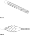
- Figs 2 and 3 an example of a cage which has been laser cut from Nitinol tube is shown.
- the laser cuts have the same feature as the braided mesh. It provides a passageway on the proximal side and acts as filter on the distal side. It may also carry circumferential elements for cutting through thrombus and separating thrombus from the wall.
- Relative movement of the distal and proximal arms controls the distance between the distal and proximal sides of the cage; this adjusts the diameter and radial strength of the cage. If the distal arm is fixed and the proximal arm is pulled proximally by the user, the diameter of the cage becomes smaller. If the proximal arm is fixed and the distal arm is being pulled, the diameter of the cage increases.
- the cage may also have a circumferential cutting element for removing/scraping thrombus from the vessel wall.
- This may be contained around or within the cage and may be composed of a round wire, flat wire, blade or a combination of these.
- Fig. 4 shows the cage with a flat wire attached the outside of the cage; the wire can scrape thrombus from the vessel wall.
- Fig 5 shows the cutting element internal to the cage, while Fig. 6 shows the cutting element of the cage as one part (in this case from a laser cut tube).
- the cutting/scraping element may also be tapered at an angle ( Fig. 7 ).
- a Cage with Self Adjustable Diameter Control Mechanism is a Cage with Self Adjustable Diameter Control Mechanism
- the cage diameter should be adjustable while it is pulled along the lumen. Also in the case of obstruction such as vascular valve it is desirable that the device be able to manoeuvre through it. Therefore a mechanism which can control the diameter of the cage by changing the resistance force is desirable. Presented here is a mechanism to control the diameter of the cage based on resistance forces.
- the vessel As the cage moves through a reducing tapered vessel (pulling the proximal arm), the vessel exerts a force on the cage. When the force from the vessel exceeds the total force including the pre-set force from the resistance mechanism (set by the user), the distal arm moves distally relative to the proximal arm; this closes the cage.
- the next section includes some embodiments of the self-adjustment mechanisms.
- the control mechanism may contain friction elements, springs, pneumatics, hydraulics, simple weight, or a combination of these elements.
- the cage (3) is made from a laser cut self-expanding tube.
- the cage opens when 1b and 2b move closer together, and closes when 1b and 2b move apart.
- the mechanism for controlling the diameter and force exerted by the cage on the vessel wall is the basis for the current invention.
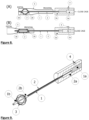
- the device as shown in Fig. 8 , consists of a cage (3) which has a distal end (1b) and a proximal end (2b), a distal arm (1), a proximal arm (2), and a handle.
- the control mechanism is comprised in the handle, and comprises a first part in the form of a housing (2a) having a guidance path, a second part in the form of a sliding block (1a) configured for sliding movement along the guidance path of the housing (2a).
- Force controlled resistance means is provided in the form of a brake adapted to resist movement of one or the arms relative to the other.
- the brake comprises a friction screw (4) mounted on the housing (2A) and adjustable to apply a compression force against the sliding block (1a) to provide resistance to movement of one arm relative to the other, and in the case of the device being passed along a vessel that tapers inwardly, resistance to the compression of the cage which has the effect of keeping the periphery of the cage in contact with the vessel wall.
- the process begins in an expanded state in the vessel as shown in Fig. 8(A) .
- the opening and closing of the cage is governed by the relative movement of the sliding block (1a) to the handle (2a).
- force from the vessel wall is exerted to the cage.
- This force is transferred to the sliding block (1a). If the force applied to the block 1a is larger than the pre-set friction force, then the block 1a slides forward from its position 2(A) to 2(B). This allows the cage to conform to the shape of the narrower vessel.
- the force exerted by the cage on the vessel is therefore dictated in part by the ease of movement of the sliding block relative to the handle; this is controlled by the friction screw.
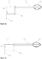
- Figs. 11A and 12B show an alternative embodiment of the resistance mechanism in which parts described with reference to Fig. 10 are assigned the same reference numerals.
- a compression spring (6) is disposed along the guide path between the housing (2a) and the sliding block (1a).
- the housing (2a) is connected to the proximal arm (2) and the block (1a) is connected to the distal arm (1).
- compression of the cage (3) into a contracted orientation causes the distal arm (1) to extend, causing compression of the spring.
- the cage is biased into an expanded orientation when it is being passed along a vessel that is narrowing, thereby maintaining contact between the cage and the vessel wall.
- a friction screw (4) is mounted on the housing (2A) and is adjustable to apply a compression force against the block (1A) and thereby provides further resistance to movement of one arm relative to the other, and in the case of the device being passed along a vessel that tapers inwardly, again provides resistance to the compression of the cage which has the effect of keeping the periphery of the cage in contact with the vessel wall.
- Figs. 11A and 11B show an alternative embodiment of the resistance mechanism in which parts described with reference to Figs. 8 to 10 are assigned the same reference numerals.
- the self-adjusting mechanism comprises a movable stop (7) that is movable to adjust the length of the guidance path and, thus, the degree of compression of the spring.
- the force that the spring applies can be varied by changing the position of the movable stop (7) along the guidance path.
- the distal arm (1) is attached to a flat spring (22).
- the other side of the spring (22) is fixed respect to proximal arm (2) through a solid handle (20). Since the spring constant of a flat spring changes with its length, a mechanism for adjusting its length (21) can slide over the spring to control its deformation.
- the spring constant is the lowest which means it allows higher displacement of inner tube (1) at a lower force.
- the spring constant (22) increases which allows less displacement of inner tube (1). This effectively reduces the cage diameter (3).
- Fig. 14 shows a 3D representation of the mechanism.
- the extraction system may consist of suction, or a rotating tube/wire with a means of transformation and/or maceration on the outer surface; the extraction system may also contain a combination of these mechanisms.
- the rotating extractor may be manufactured from one part or made from several attachments.
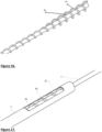
- the extraction mechanism may comprise a wire (42) wrapped around an extraction core tube (43) ( Fig. 15 ). This tube may be placed over the distal arm (1) of the cage and inside the proximal arm (2). Alternatively, the distal arm may be used as the extraction core tube. The distal side of the extraction core tube may be close to the distal end of the proximal arm (2). As the extraction tube turns at high speed thrombus is forced proximally between the extraction tube and the proximal arm. The distal end of the extraction mechanism may be located inside the cage ( Fig. 1 ).
- the wire may have varying cross sections along the device for different means; from circular, rectangular or triangular cross sections.
- the wire can be from different materials such as stainless steel, Nitinol, or polymers.
- the proximal arm may also contain a side window ( Fig. 17 ) to improve access of the extractor to thrombus.
- the extractor may also be formed from one machined part rather than a wire wrapped around a tube.
- the rotating extractor will likely contain sharp cutting edges at its distal end to break up matter prior to extracting it.
- the non-rotating proximal arm may also have a leading edge/cutting element (Fi. 18) which helps to break down thrombus, while also increasing the size of the path at the entrance of the extractor.
- the proximal arm may have more than one leading edge/cutting element to break down matter; Figure 19 shows the proximal arm with two leading edges.
- the leading edge/cutting element may form part of the proximal arm (as shown) or alternatively be a separate part attached to the non-rotating proximal arm.
- the extractor may also contain an additional port at the proximal end where suction can be added to enhance thrombus extraction, and to attract thrombus towards the extractor.
- Fig. 20 shows an embodiment in which the rotating tip and helical wire are attached to the distal arm for rotation therewith.
- Fig. 21 shows the extractor with the cage.
- the extractor may also be eccentric to the centre of the cage;
- Fig. 22 shows the extractor eccentric to the centre cage and adjacent to it while Fig.23 shows the tip of the cage away from the centre of the cage. In both Figs 22 and 23 the extractor may be stationary or rotate around the centreline.
- the extractor may have a varied pitch along its length.
- a section of the extractor has a reduced pitch
- the non-rotating tube has a number of small holes (acting as a filter) in it. This may allow any debris to be squeezed, forcing residual fluid through the holes and into the vessel while the remaining debris continues to be extracted.
- the extraction mechanism in combination with the cage may have various functions along the device.
- the extractor breaks down the thrombi into relatively big pieces which are small enough to enter the inlet of tube and big enough not to pass through the filter. Once the thrombus is inside the tube, the extractor, breaks them down into smaller pieces, make it easier to transfer along the catheter.
- the extraction system may have a means of extraction such as helical wire or vacuum. The matter removed will be collected in a suitable collection means, for example a blood bag, or syringe or similar.
- the helical formation may have a cutting edge, and which is adapted to rotate with the helical formation and cut or break up thrombus for extraction.
- the cutting edge may be a blade ore the like, and may be disposed at or close to an end of the helical formation.
- the extractor tube may also have a cutting edge, and may be adapted to rotate.
- the device contains both a cage with a self-adjustment mechanism, and an extractor.
- Fig. 25 shows an embodiment of the distal end of the device.
- the device is opened and closed by the relative movement of the proximal and distal arms, while the extractor rotates over the distal arm and within the proximal arm.
- the proximal arm may also contain a window for extraction.
- a sheath covers the entire device during delivery and retrieval.
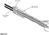
- Fig. 26 shows another embodiment of the distal end of the device, with the cage and extractor combined.
- the rotating extractor also acts at the distal arm; the relative movement of which opens and closes the cage.
- a ball bearing has been included to facilitate contact of the rotating extractor/distal arm and non-rotating proximal arm and cage (27).
- Fig. 28 shows an embodiment of the device in which the control mechanism is disposed within the cage.
- a control mechanism is provided within the cage (3) and comprises a first part operably connected to the proximal arm (2), a second part operably connected to the distal arm (1), and a helical spring (6) connecting the first and second parts.
- the control mechanism ensures that a force controlled resistance is applied to the cage as it contracts, thereby ensuring that the cage remains in contact with the walls of the vessel.
- Fig. 29 shows an embodiment of the device in which the control mechanism is disposed distally of the cage.
- the device comprises a proximal arm (2), which is connected to a proximal part (2b) of the cage and which extends through, and distally beyond, the cage, and a distal arm (1) which extends distally of the cage (3).
- the control mechanism comprises a first part (block 1b) operably connected to an end of the proximal arm, a second part operably connected to the distal arm (1), and a helical spring (6).
- the control mechanism ensures that a force controlled resistance is applied to the cage as it contracts, thereby ensuring that the cage remains in contact with the walls of the vessel.
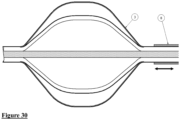
- Fig. 30 shows an embodiment of the device of the invention in which a sheath (8) is provided that covers the elongated control member.
- the device can be manipulated such that the cage (3) is contracted and withdrawn within the sheath, which will thus keep it in a contracted orientation
- the device of the invention may also be employed to deliver liquid agent, for example a thrombolytic agent which can break down thrombus, to the vessel lumen.
- liquid agent for example a thrombolytic agent which can break down thrombus
- the liquid agent would be injected into the delivery lumen, which may be any of the above.
- the liquid agent may be delivered slowly by means of a drip feed.
- the liquid agent may be delivered in a number of different ways, for example through a hollow distal arm (which has the advantage of being capable of delivering liquid agent distally of the cage), through a lumen formed between the distal arm and the proximal arm (also referred to as the extractor tube), or through a lumen formed between the proximal arm and the outer sheath.
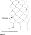
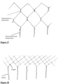
- Figs 34 to 39 describe embodiments of the radially expansible member forming part of the device of the invention, and specifically braid configurations that may be employed in radially expansible members.
Landscapes
- Health & Medical Sciences (AREA)
- Surgery (AREA)
- Life Sciences & Earth Sciences (AREA)
- Heart & Thoracic Surgery (AREA)
- Nuclear Medicine, Radiotherapy & Molecular Imaging (AREA)
- Engineering & Computer Science (AREA)
- Biomedical Technology (AREA)
- Medical Informatics (AREA)
- Molecular Biology (AREA)
- Animal Behavior & Ethology (AREA)
- General Health & Medical Sciences (AREA)
- Public Health (AREA)
- Veterinary Medicine (AREA)
- Vascular Medicine (AREA)
- Orthopedic Medicine & Surgery (AREA)
- Surgical Instruments (AREA)
Applications Claiming Priority (4)
| Application Number | Priority Date | Filing Date | Title |
|---|---|---|---|
| EP13159640 | 2013-03-15 | ||
| EP16201115.9A EP3202340B1 (en) | 2013-03-15 | 2014-03-18 | A device suitable for removing matter from inside the lumen and the wall of a body lumen |
| EP14716029.5A EP2967614B1 (en) | 2013-03-15 | 2014-03-18 | A device suitable for removing matter from inside the lumen and the wall of a body lumen |
| PCT/IE2014/000005 WO2014141226A1 (en) | 2013-03-15 | 2014-03-18 | A device suitable for removing matter from inside the lumen and the wall of a body lumen |
Related Parent Applications (3)
| Application Number | Title | Priority Date | Filing Date |
|---|---|---|---|
| EP16201115.9A Division-Into EP3202340B1 (en) | 2013-03-15 | 2014-03-18 | A device suitable for removing matter from inside the lumen and the wall of a body lumen |
| EP16201115.9A Division EP3202340B1 (en) | 2013-03-15 | 2014-03-18 | A device suitable for removing matter from inside the lumen and the wall of a body lumen |
| EP14716029.5A Division EP2967614B1 (en) | 2013-03-15 | 2014-03-18 | A device suitable for removing matter from inside the lumen and the wall of a body lumen |
Publications (2)
| Publication Number | Publication Date |
|---|---|
| EP3305221A1 EP3305221A1 (en) | 2018-04-11 |
| EP3305221B1 true EP3305221B1 (en) | 2023-06-14 |
Family
ID=47997034
Family Applications (4)
| Application Number | Title | Priority Date | Filing Date |
|---|---|---|---|
| EP17198610.2A Active EP3305221B1 (en) | 2013-03-15 | 2014-03-18 | A device suitable for removing matter from inside the lumen and the wall of a body lumen |
| EP14716029.5A Active EP2967614B1 (en) | 2013-03-15 | 2014-03-18 | A device suitable for removing matter from inside the lumen and the wall of a body lumen |
| EP17198529.4A Active EP3305220B8 (en) | 2013-03-15 | 2014-03-18 | A device suitable for removing matter from inside the lumen and the wall of a body lumen |
| EP16201115.9A Active EP3202340B1 (en) | 2013-03-15 | 2014-03-18 | A device suitable for removing matter from inside the lumen and the wall of a body lumen |
Family Applications After (3)
| Application Number | Title | Priority Date | Filing Date |
|---|---|---|---|
| EP14716029.5A Active EP2967614B1 (en) | 2013-03-15 | 2014-03-18 | A device suitable for removing matter from inside the lumen and the wall of a body lumen |
| EP17198529.4A Active EP3305220B8 (en) | 2013-03-15 | 2014-03-18 | A device suitable for removing matter from inside the lumen and the wall of a body lumen |
| EP16201115.9A Active EP3202340B1 (en) | 2013-03-15 | 2014-03-18 | A device suitable for removing matter from inside the lumen and the wall of a body lumen |
Country Status (5)
| Country | Link |
|---|---|
| US (9) | US10813663B2 (enExample) |
| EP (4) | EP3305221B1 (enExample) |
| JP (4) | JP6435280B2 (enExample) |
| ES (1) | ES2617711T3 (enExample) |
| WO (1) | WO2014141226A1 (enExample) |
Families Citing this family (104)
| Publication number | Priority date | Publication date | Assignee | Title |
|---|---|---|---|---|
| US7686825B2 (en) | 2004-03-25 | 2010-03-30 | Hauser David L | Vascular filter device |
| US11589880B2 (en) | 2007-12-20 | 2023-02-28 | Angiodynamics, Inc. | System and methods for removing undesirable material within a circulatory system utilizing during a surgical procedure |
| US10517617B2 (en) | 2007-12-20 | 2019-12-31 | Angiodynamics, Inc. | Systems and methods for removing undesirable material within a circulatory system utilizing a balloon catheter |
| US20170136158A1 (en) | 2015-10-16 | 2017-05-18 | Angiodynamics, Inc. | Systems and Methods for Removing Undesirable Material Within a Circulatory System |
| US12245788B2 (en) | 2011-03-15 | 2025-03-11 | Angiodynamics, Inc. | Device and method for removing material from a hollow anatomical structure |
| US9055964B2 (en) | 2011-03-15 | 2015-06-16 | Angio Dynamics, Inc. | Device and method for removing material from a hollow anatomical structure |
| WO2014047650A1 (en) | 2012-09-24 | 2014-03-27 | Inceptus Medical LLC | Device and method for treating vascular occlusion |
| US8784434B2 (en) | 2012-11-20 | 2014-07-22 | Inceptus Medical, Inc. | Methods and apparatus for treating embolism |
| US9279058B2 (en) | 2013-01-11 | 2016-03-08 | Floor Iptech Ab | Digital embossing |
| JP6437517B2 (ja) | 2013-03-15 | 2018-12-12 | インセラ セラピューティクス,インク. | 血管治療装置及び方法 |
| US8679150B1 (en) | 2013-03-15 | 2014-03-25 | Insera Therapeutics, Inc. | Shape-set textile structure based mechanical thrombectomy methods |
| US8690907B1 (en) | 2013-03-15 | 2014-04-08 | Insera Therapeutics, Inc. | Vascular treatment methods |
| EP3305221B1 (en) | 2013-03-15 | 2023-06-14 | Vetex Medical Limited | A device suitable for removing matter from inside the lumen and the wall of a body lumen |
| US8715314B1 (en) | 2013-03-15 | 2014-05-06 | Insera Therapeutics, Inc. | Vascular treatment measurement methods |
| US10238406B2 (en) | 2013-10-21 | 2019-03-26 | Inari Medical, Inc. | Methods and apparatus for treating embolism |
| EP3213699A4 (en) | 2014-10-27 | 2018-04-18 | Terumo Kabushiki Kaisha | Medical device |
| EP3017775A1 (en) | 2014-11-07 | 2016-05-11 | National University of Ireland, Galway | A thrombectomy device |
| US9999493B2 (en) | 2015-08-06 | 2018-06-19 | Kp Medcure, Inc. | Axial lengthening thrombus capture system |
| US9744024B2 (en) | 2015-08-06 | 2017-08-29 | Kp Medcure, Inc. | Axial lengthening thrombus capture system |
| US9579116B1 (en) | 2015-08-06 | 2017-02-28 | Kp Medcure, Inc. | Axial lengthening thrombus capture system |
| AU2016341439B2 (en) | 2015-10-23 | 2021-07-08 | Stryker Corporation | Intravascular treatment of vascular occlusion and associated devices, systems, and methods |
| US10342571B2 (en) | 2015-10-23 | 2019-07-09 | Inari Medical, Inc. | Intravascular treatment of vascular occlusion and associated devices, systems, and methods |
| JP2018537229A (ja) | 2015-12-18 | 2018-12-20 | イナリ メディカル, インコーポレイテッド | カテーテルシャフト並びに関連する装置、システム、及び方法 |
| CN108697423A (zh) | 2016-02-16 | 2018-10-23 | 伊瑟拉医疗公司 | 抽吸装置和锚定的分流装置 |
| JP7012655B2 (ja) | 2016-02-24 | 2022-01-28 | インセプト、リミテッド、ライアビリティ、カンパニー | 可撓性の強化された神経血管カテーテル |
| CN108778165B (zh) * | 2016-03-09 | 2021-12-07 | 泰尔茂株式会社 | 医疗器械及处置方法 |
| JP2019071913A (ja) * | 2016-03-09 | 2019-05-16 | テルモ株式会社 | 医療デバイスおよび処置方法 |
| CN106073856B (zh) * | 2016-05-16 | 2018-09-18 | 西安交通大学第一附属医院 | 一种心血管栓塞介入取栓装置 |
| CN105943118A (zh) * | 2016-05-18 | 2016-09-21 | 辽宁垠艺生物科技股份有限公司 | 医用多功能抓捕切割器 |
| DE102016110326B4 (de) * | 2016-06-03 | 2019-05-16 | Fraunhofer-Gesellschaft zur Förderung der angewandten Forschung e.V. | Verfahren und Vorrichtung zur Herstellung einer Drahtkorbeinheit sowie Drahtkorbeinheit |
| CN116421266A (zh) | 2016-10-24 | 2023-07-14 | 伊纳里医疗有限公司 | 用于治疗血管闭塞的装置和方法 |
| US10517708B2 (en) * | 2016-10-26 | 2019-12-31 | DePuy Synthes Products, Inc. | Multi-basket clot capturing device |
| US11134930B2 (en) | 2016-11-11 | 2021-10-05 | Bernd Holthaus | Device for removing organs from a human or animal body |
| WO2018112221A1 (en) * | 2016-12-16 | 2018-06-21 | Boston Scientific Scimed, Inc. | Medical device handles and related methods |
| EP3565511B1 (en) * | 2017-01-06 | 2023-10-18 | Incept, LLC | Thromboresistant coatings for aneurysm treatment devices |
| EP3579765B1 (en) * | 2017-02-08 | 2023-08-30 | Vascular Medcure, Inc. | Axial lengthening thrombus capture system |
| WO2018147449A1 (ja) | 2017-02-10 | 2018-08-16 | 川澄化学工業株式会社 | 異物除去デバイス、異物除去用カテーテル及び異物回収システム |
| EP3589243B1 (en) | 2017-02-28 | 2024-09-11 | University College Cork - National University of Ireland, Cork | An intravascular cell therapy device |
| JP7125766B2 (ja) | 2017-04-05 | 2022-08-25 | ナショナル・ユニバーシティ・オブ・アイルランド・ガルウェイ | 植え込み型医療装置 |
| JP7693276B2 (ja) * | 2017-04-06 | 2025-06-17 | リフロー メディカル インコーポレイテッド | 突出フィーチャを有するステントのための送達システム |
| IL252608B (en) * | 2017-06-01 | 2021-06-30 | Amnis Therapeutics Ltd | Device for extracting blood clots |
| US10478322B2 (en) * | 2017-06-19 | 2019-11-19 | Covidien Lp | Retractor device for transforming a retrieval device from a deployed position to a delivery position |
| DK3678731T3 (da) | 2017-09-06 | 2025-01-02 | Inari Medical Inc | Hemostasis valves and methods of use |
| US10258357B1 (en) | 2017-10-16 | 2019-04-16 | Michael Bruce Horowitz | Catheter based retrieval device with proximal body having axial freedom of movement |
| WO2022082213A1 (en) | 2017-10-16 | 2022-04-21 | Retriever Medical, Inc. | Clot removal methods and devices with multiple independently controllable elements |
| US12201315B2 (en) | 2017-10-16 | 2025-01-21 | Retriever Medical, Inc. | Clot removal methods and devices with multiple independently controllable elements |
| US12433634B2 (en) | 2017-12-21 | 2025-10-07 | W. L. Gore & Associates, Inc. | Catheter-based occlusion removal systems and method |
| CA3084506C (en) | 2017-12-21 | 2022-10-04 | W. L. Gore & Associates, Inc. | Catheter-based occlusion removal systems and methods |
| US11154314B2 (en) | 2018-01-26 | 2021-10-26 | Inari Medical, Inc. | Single insertion delivery system for treating embolism and associated systems and methods |
| US11395665B2 (en) | 2018-05-01 | 2022-07-26 | Incept, Llc | Devices and methods for removing obstructive material, from an intravascular site |
| EP3787523A4 (en) | 2018-05-01 | 2022-02-23 | Incept, LLC | DEVICES AND METHODS FOR REMOVAL OF OBSTRUCTIVE MATERIAL FROM AN INTRAVASCULAR SITE |
| EP3793459B1 (en) | 2018-05-18 | 2024-07-10 | National University of Ireland Galway | A device for denuding a body lumen |
| CN119385661A (zh) * | 2018-06-04 | 2025-02-07 | 帕维尔·V·埃弗雷金 | 体内手术用装置和方法 |
| US10898216B2 (en) | 2018-06-13 | 2021-01-26 | DePuy Synthes Products, Inc. | Vasculature obstruction capture device |
| WO2020010310A1 (en) | 2018-07-06 | 2020-01-09 | Imperative Care, Inc. | Sealed neurovascular extendable catheter |
| US11471582B2 (en) | 2018-07-06 | 2022-10-18 | Incept, Llc | Vacuum transfer tool for extendable catheter |
| CN119112290A (zh) * | 2018-08-10 | 2024-12-13 | 铸造有限责任公司 | 机械式静脉凝块取出 |
| US11559382B2 (en) | 2018-08-13 | 2023-01-24 | Inari Medical, Inc. | System for treating embolism and associated devices and methods |
| WO2020051468A1 (en) * | 2018-09-07 | 2020-03-12 | Merit Medical Systems, Inc. | Thrombosis macerating and aspiration devices for blood vessels |
| EP3636171A1 (en) | 2018-10-11 | 2020-04-15 | National University of Ireland Galway | A device for implantation in a left atrial appendage of the heart |
| EP3917417A1 (en) | 2019-01-31 | 2021-12-08 | Merit Medical Systems, Inc. | Thrombosis macerating devices for blood vessels |
| US11766539B2 (en) | 2019-03-29 | 2023-09-26 | Incept, Llc | Enhanced flexibility neurovascular catheter |
| EP3975872B1 (en) * | 2019-05-31 | 2025-08-06 | MicroVention, Inc. | Clot retrieval |
| US12274844B2 (en) | 2019-06-24 | 2025-04-15 | Covidien Lp | Thrombus removal device |
| US11986194B2 (en) | 2019-09-18 | 2024-05-21 | Merit Medical Systems, Inc. | Torque cable |
| WO2021076642A1 (en) | 2019-10-15 | 2021-04-22 | Imperative Care, Inc. | Systems and methods for multivariate stroke detection |
| CA3157521A1 (en) | 2019-10-16 | 2021-04-22 | Inari Medical, Inc. | Systems, devices, and methods for treating vascular occlusions |
| CN115175638B (zh) | 2019-11-05 | 2025-09-26 | 瓦斯科尔勒治疗股份有限公司 | 轴向伸长的血栓捕获系统、张紧系统和可扩展漏斗导管 |
| EP4076611A4 (en) | 2019-12-18 | 2023-11-15 | Imperative Care, Inc. | Methods and systems for treating venous thromboembolic disease |
| US11439799B2 (en) | 2019-12-18 | 2022-09-13 | Imperative Care, Inc. | Split dilator aspiration system |
| US11638637B2 (en) | 2019-12-18 | 2023-05-02 | Imperative Care, Inc. | Method of removing embolic material with thrombus engagement tool |
| US11648020B2 (en) | 2020-02-07 | 2023-05-16 | Angiodynamics, Inc. | Device and method for manual aspiration and removal of an undesirable material |
| US11090174B1 (en) | 2020-02-11 | 2021-08-17 | Amaitus, Inc. | Temporary and retrievable expandable member |
| CN115460999A (zh) | 2020-03-04 | 2022-12-09 | 施菲姆德控股有限责任公司 | 血栓去除系统及相关方法 |
| CN118925025A (zh) | 2020-03-10 | 2024-11-12 | 因普瑞缇夫护理公司 | 增强的柔韧性的神经血管导管 |
| EP4663214A3 (en) | 2020-06-05 | 2026-02-25 | Inari Medical, Inc. | Recapturable funnel catheters, and associated systems |
| JP7776876B2 (ja) | 2020-06-05 | 2025-11-27 | グラビティ メディカル テクノロジー, インコーポレイテッド | 流動を回復させるための方法および装置 |
| US11207497B1 (en) | 2020-08-11 | 2021-12-28 | Imperative Care, Inc. | Catheter with enhanced tensile strength |
| CN112617963B (zh) * | 2020-12-28 | 2023-09-29 | 吉林一方科技有限公司 | 一种血栓清除装置 |
| US11471183B1 (en) * | 2021-02-18 | 2022-10-18 | Boston Scientific Scimed, Inc. | Thrombectomy methods |
| US11504151B2 (en) | 2021-02-18 | 2022-11-22 | Boston Scientific Scimed, Inc. | Thrombectomy apparatuses |
| US12390236B2 (en) | 2021-03-10 | 2025-08-19 | Covidien Lp | Thrombus removal device |
| US12433735B2 (en) | 2021-03-10 | 2025-10-07 | Intervene, Inc. | Interventional systems and associated devices and methods |
| WO2022195875A1 (ja) * | 2021-03-19 | 2022-09-22 | テルモ株式会社 | 医療デバイス |
| EP4079239B1 (en) * | 2021-04-22 | 2025-07-02 | Vetex Medical Ltd. | A thrombectomy device |
| US12558175B2 (en) | 2021-08-12 | 2026-02-24 | Imperative Care, Inc. | Multi catheter method of performing a robotic neurovascular procedure |
| USD1077996S1 (en) | 2021-10-18 | 2025-06-03 | Imperative Care, Inc. | Inline fluid filter |
| US20250057565A1 (en) * | 2021-12-17 | 2025-02-20 | Clearstream Technologies Limited | Catheter device for extracting an occlusion from a blood vessel |
| US12364496B2 (en) | 2022-01-11 | 2025-07-22 | Inari Medical, Inc. | Devices for removing clot material from intravascularly implanted devices, and associated systems and methods |
| EP4468973A1 (en) * | 2022-01-27 | 2024-12-04 | Contego Medical, Inc. | Thrombectomy and aspiration system and methods of use |
| IL314860A (en) * | 2022-02-11 | 2024-10-01 | Revelle Aesthetics Inc | Systems and methods for aesthetic treatment |
| US20250213260A1 (en) * | 2022-03-31 | 2025-07-03 | Clearstream Technologies Limited | Vascular device |
| WO2023211433A1 (en) * | 2022-04-27 | 2023-11-02 | Bard Peripheral Vascular, Inc. | Catheters, devices, and methods for removal of material from hollow bodies |
| JP2024006180A (ja) * | 2022-07-01 | 2024-01-17 | 学校法人関西医科大学 | 穿刺ユニット、及びこれを用いた医療用ドレナージデバイス |
| CN115281827B (zh) * | 2022-09-30 | 2023-05-23 | 深圳市爱博医疗机器人有限公司 | 一种夹持旋转装置及介入手术机器人的从端装置 |
| CN115778481A (zh) * | 2022-11-17 | 2023-03-14 | 上海康德莱医疗器械股份有限公司 | 一种切割导丝及血栓抽吸系统 |
| JP2026501789A (ja) | 2023-01-09 | 2026-01-16 | イナリ メディカル, インコーポレイテッド | 凝塊治療システムと共に使用するためのカテーテル |
| US12588925B2 (en) | 2023-01-26 | 2026-03-31 | Acotec Technologies Limited | Deep vein thrombosis thrombectomy device with embolic protection |
| CN116138843B (zh) * | 2023-04-04 | 2023-07-14 | 杭州亿科医疗科技有限公司 | 一种取栓支架可调节的取栓装置 |
| CN116058923B (zh) * | 2023-04-04 | 2023-06-20 | 杭州亿科医疗科技有限公司 | 复合型取栓支架、取栓装置及取栓系统 |
| AU2024380408A1 (en) | 2023-11-16 | 2026-05-07 | Inari Medical, Inc. | Automatic locking and unlocking vacuum syringes, and associated systems and methods |
| CN117731362B (zh) | 2024-01-09 | 2024-08-09 | 苏州中天医疗器械科技有限公司 | 一种远端血栓移除器 |
| US12465382B1 (en) | 2024-05-10 | 2025-11-11 | Inari Medical, Inc. | Mechanical thrombectomy assemblies with relief features, and associated devices, systems, and methods |
| WO2025240515A1 (en) * | 2024-05-13 | 2025-11-20 | Shifamed Holdings, Llc | Thrombus removal systems and associated methods |
Family Cites Families (182)
| Publication number | Priority date | Publication date | Assignee | Title |
|---|---|---|---|---|
| EP0117519A1 (de) * | 1983-02-23 | 1984-09-05 | Johannes Dipl.-Ing. Theermann | Katheter |
| US4909789A (en) * | 1986-03-28 | 1990-03-20 | Olympus Optical Co., Ltd. | Observation assisting forceps |
| JPH0135280Y2 (enExample) | 1986-08-07 | 1989-10-26 | ||
| BR8706114A (pt) * | 1986-11-14 | 1988-06-21 | Squibb & Sons Inc | Aparelhagem ablativa giratoria acionada a gas para aplicacoes medicas |
| US5156610A (en) * | 1989-08-18 | 1992-10-20 | Evi Corporation | Catheter atherotome |
| AU6515490A (en) | 1989-09-29 | 1991-04-28 | Alan S. Feit | Coronary thrombectomy apparatus and method of use |
| US5092839A (en) | 1989-09-29 | 1992-03-03 | Kipperman Robert M | Coronary thrombectomy |
| US5135517A (en) * | 1990-07-19 | 1992-08-04 | Catheter Research, Inc. | Expandable tube-positioning apparatus |
| US5100423A (en) * | 1990-08-21 | 1992-03-31 | Medical Engineering & Development Institute, Inc. | Ablation catheter |
| US5190557A (en) | 1991-10-03 | 1993-03-02 | Urological Instrument Research, Inc. | Vibratory method and instrument for extracting stones from urinary tract |
| WO1993019679A1 (en) | 1992-04-07 | 1993-10-14 | The Johns Hopkins University | A percutaneous mechanical fragmentation catheter system |
| US5490859A (en) | 1992-11-13 | 1996-02-13 | Scimed Life Systems, Inc. | Expandable intravascular occlusion material removal devices and methods of use |
| US5836868A (en) * | 1992-11-13 | 1998-11-17 | Scimed Life Systems, Inc. | Expandable intravascular occlusion material removal devices and methods of use |
| WO1994024946A1 (en) * | 1993-04-29 | 1994-11-10 | Scimed Life Systems, Inc. | Expandable intravascular occlusion material removal device |
| US5370653A (en) | 1993-07-22 | 1994-12-06 | Micro Therapeutics, Inc. | Thrombectomy method and apparatus |
| DE9409484U1 (de) | 1994-06-11 | 1994-08-04 | Naderlinger, Eduard, 50127 Bergheim | Vena-cava Thromben-Filter |
| US5722401A (en) | 1994-10-19 | 1998-03-03 | Cardiac Pathways Corporation | Endocardial mapping and/or ablation catheter probe |
| US5573530A (en) | 1994-12-15 | 1996-11-12 | Cabot Technology Corporation | Handle for a surgical instrument including a manually actuated brake |
| CZ287327B6 (en) * | 1995-03-28 | 2000-10-11 | Straub Medical Ag | Catheter |
| US5795322A (en) | 1995-04-10 | 1998-08-18 | Cordis Corporation | Catheter with filter and thrombus-discharge device |
| US5827229A (en) | 1995-05-24 | 1998-10-27 | Boston Scientific Corporation Northwest Technology Center, Inc. | Percutaneous aspiration thrombectomy catheter system |
| US6066158A (en) | 1996-07-25 | 2000-05-23 | Target Therapeutics, Inc. | Mechanical clot encasing and removal wire |
| US5972019A (en) | 1996-07-25 | 1999-10-26 | Target Therapeutics, Inc. | Mechanical clot treatment device |
| US6755846B1 (en) * | 1997-02-03 | 2004-06-29 | Angioguard, Inc. | Vascular filter |
| US5772674A (en) | 1997-03-31 | 1998-06-30 | Nakhjavan; Fred K. | Catheter for removal of clots in blood vessels |
| US5817104A (en) * | 1997-04-30 | 1998-10-06 | C.R. Bard, Inc. | Dual purpose mechanism for expanding baskets |
| US5911734A (en) | 1997-05-08 | 1999-06-15 | Embol-X, Inc. | Percutaneous catheter and guidewire having filter and medical device deployment capabilities |
| WO2001028618A2 (en) | 1999-10-22 | 2001-04-26 | Boston Scientific Corporation | Double balloon thrombectomy catheter |
| US7037316B2 (en) | 1997-07-24 | 2006-05-02 | Mcguckin Jr James F | Rotational thrombectomy device |
| US6066149A (en) | 1997-09-30 | 2000-05-23 | Target Therapeutics, Inc. | Mechanical clot treatment device with distal filter |
| JP2002502626A (ja) | 1998-02-10 | 2002-01-29 | アーテミス・メディカル・インコーポレイテッド | 補足装置およびその使用方法 |
| US6206842B1 (en) | 1998-08-03 | 2001-03-27 | Lily Chen Tu | Ultrasonic operation device |
| US7128073B1 (en) | 1998-11-06 | 2006-10-31 | Ev3 Endovascular, Inc. | Method and device for left atrial appendage occlusion |
| US20020138094A1 (en) | 1999-02-12 | 2002-09-26 | Thomas Borillo | Vascular filter system |
| US6146396A (en) * | 1999-03-05 | 2000-11-14 | Board Of Regents, The University Of Texas System | Declotting method and apparatus |
| WO2000067665A1 (en) | 1999-05-07 | 2000-11-16 | Salviac Limited | Support frame for embolic protection device |
| US7014647B2 (en) | 1999-05-07 | 2006-03-21 | Salviac Limited | Support frame for an embolic protection device |
| US6179859B1 (en) | 1999-07-16 | 2001-01-30 | Baff Llc | Emboli filtration system and methods of use |
| US7320697B2 (en) | 1999-07-30 | 2008-01-22 | Boston Scientific Scimed, Inc. | One piece loop and coil |
| US20020026211A1 (en) | 1999-12-23 | 2002-02-28 | Farhad Khosravi | Vascular device having emboli and thrombus removal element and methods of use |
| US6371970B1 (en) | 1999-07-30 | 2002-04-16 | Incept Llc | Vascular filter having articulation region and methods of use in the ascending aorta |
| WO2001008743A1 (en) | 1999-07-30 | 2001-02-08 | Incept Llc | Vascular device for emboli, thrombus and foreign body removal and methods of use |
| US6530939B1 (en) | 1999-07-30 | 2003-03-11 | Incept, Llc | Vascular device having articulation region and methods of use |
| US6203561B1 (en) | 1999-07-30 | 2001-03-20 | Incept Llc | Integrated vascular device having thrombectomy element and vascular filter and methods of use |
| US6179861B1 (en) | 1999-07-30 | 2001-01-30 | Incept Llc | Vascular device having one or more articulation regions and methods of use |
| US7306618B2 (en) | 1999-07-30 | 2007-12-11 | Incept Llc | Vascular device for emboli and thrombi removal and methods of use |
| US7229462B2 (en) * | 1999-07-30 | 2007-06-12 | Angioguard, Inc. | Vascular filter system for carotid endarterectomy |
| US6544279B1 (en) | 2000-08-09 | 2003-04-08 | Incept, Llc | Vascular device for emboli, thrombus and foreign body removal and methods of use |
| US6616679B1 (en) | 1999-07-30 | 2003-09-09 | Incept, Llc | Rapid exchange vascular device for emboli and thrombus removal and methods of use |
| EP1207933B1 (en) | 1999-07-30 | 2011-05-11 | Incept Llc | Vascular filter having articulation region |
| US6620182B1 (en) | 1999-07-30 | 2003-09-16 | Incept Llc | Vascular filter having articulation region and methods of use in the ascending aorta |
| US6346116B1 (en) * | 1999-08-03 | 2002-02-12 | Medtronic Ave, Inc. | Distal protection device |
| AU778076B2 (en) | 1999-09-17 | 2004-11-11 | Tyco Healthcare Group Lp | Mechanical pump for removal of fragmented matter and methods of manufacture and use |
| US6454775B1 (en) | 1999-12-06 | 2002-09-24 | Bacchus Vascular Inc. | Systems and methods for clot disruption and retrieval |
| US7655016B2 (en) | 1999-09-17 | 2010-02-02 | Covidien | Mechanical pump for removal of fragmented matter and methods of manufacture and use |
| US6702830B1 (en) | 1999-09-17 | 2004-03-09 | Bacchus Vascular, Inc. | Mechanical pump for removal of fragmented matter and methods of manufacture and use |
| US8414543B2 (en) | 1999-10-22 | 2013-04-09 | Rex Medical, L.P. | Rotational thrombectomy wire with blocking device |
| US6632241B1 (en) | 2000-03-22 | 2003-10-14 | Endovascular Technologies, Inc. | Self-expanding, pseudo-braided intravascular device |
| US20010031981A1 (en) * | 2000-03-31 | 2001-10-18 | Evans Michael A. | Method and device for locating guidewire and treating chronic total occlusions |
| GB2369575A (en) | 2000-04-20 | 2002-06-05 | Salviac Ltd | An embolic protection system |
| FR2808991A1 (fr) * | 2000-05-18 | 2001-11-23 | Perret Emile Lamy | Sonde extensible interne a usage chirurgical pour la dilatation, le curetage et la protection de conduits physiologiques |
| US6964670B1 (en) | 2000-07-13 | 2005-11-15 | Advanced Cardiovascular Systems, Inc. | Embolic protection guide wire |
| US6558405B1 (en) | 2000-08-29 | 2003-05-06 | Advanced Cardiovascular Systems, Inc. | Embolic filter |
| AU2002324417A1 (en) | 2001-01-16 | 2002-12-03 | Incept Llc | Vascular device for emboli and thrombi removal |
| US6610077B1 (en) | 2001-01-23 | 2003-08-26 | Endovascular Technologies, Inc. | Expandable emboli filter and thrombectomy device |
| US6635070B2 (en) | 2001-05-21 | 2003-10-21 | Bacchus Vascular, Inc. | Apparatus and methods for capturing particulate material within blood vessels |
| US20020188314A1 (en) | 2001-06-07 | 2002-12-12 | Microvena Corporation | Radiopaque distal embolic protection device |
| US6656203B2 (en) | 2001-07-18 | 2003-12-02 | Cordis Corporation | Integral vascular filter system |
| WO2003018085A2 (en) | 2001-08-22 | 2003-03-06 | Arteria Medical Science, Inc. | Apparatus and methods for treating stroke and controlling cerebral flow characteristics |
| US20030176884A1 (en) | 2002-03-12 | 2003-09-18 | Marwane Berrada | Everted filter device |
| US7083633B2 (en) | 2002-09-03 | 2006-08-01 | Advanced Vascular Technologies Llc | Arterial embolic filter deployed from catheter |
| DE10242444A1 (de) * | 2002-09-11 | 2004-04-01 | pfm Produkte für die Medizin AG | Extraktionsvorrichtung |
| US20100094320A1 (en) | 2002-10-29 | 2010-04-15 | Microfabrica Inc. | Atherectomy and Thrombectomy Devices, Methods for Making, and Procedures for Using |
| JP4335814B2 (ja) * | 2002-12-23 | 2009-09-30 | リソテック メディカル リミテッド | 異物を摘出するための外科用装置およびその製造方法 |
| JP2005006779A (ja) * | 2003-06-17 | 2005-01-13 | Terumo Corp | 生体管腔洗浄装置 |
| US7220269B1 (en) | 2003-11-06 | 2007-05-22 | Possis Medical, Inc. | Thrombectomy catheter system with occluder and method of using same |
| US7988705B2 (en) * | 2004-03-06 | 2011-08-02 | Lumen Biomedical, Inc. | Steerable device having a corewire within a tube and combination with a functional medical component |
| US8403976B2 (en) | 2004-04-08 | 2013-03-26 | Contego Medical Llc | Percutaneous transluminal angioplasty device with integral embolic filter |
| WO2005112770A1 (en) | 2004-05-13 | 2005-12-01 | Omnisonics Medical Technologies, Inc. | Ultrasonic medical device and method for treating urolithiasis |
| US9655633B2 (en) | 2004-09-10 | 2017-05-23 | Penumbra, Inc. | System and method for treating ischemic stroke |
| CA2541321A1 (en) | 2005-03-31 | 2006-09-30 | Sherwood Services Ag | Percutaneous or surgical radiofrequency intravascular thrombectomy catheter system and method |
| US8603122B2 (en) | 2005-04-01 | 2013-12-10 | Nexgen Medical Systems, Incorporated | Thrombus removal system and process |
| US7955345B2 (en) | 2005-04-01 | 2011-06-07 | Nexgen Medical Systems, Inc. | Thrombus removal system and process |
| US7955344B2 (en) | 2005-04-01 | 2011-06-07 | Nexgen Medical Systems, Inc. | Thrombus removal system and process |
| JP4330571B2 (ja) * | 2005-04-01 | 2009-09-16 | ドナルド ホッキング ゴードン | 捕捉装置 |
| US8475487B2 (en) | 2005-04-07 | 2013-07-02 | Medrad, Inc. | Cross stream thrombectomy catheter with flexible and expandable cage |
| US7645290B2 (en) | 2005-05-05 | 2010-01-12 | Lucas Paul R | Multi-functional thrombectomy device |
| US7806871B2 (en) | 2005-05-09 | 2010-10-05 | Boston Scientific Scimed, Inc. | Method and device for tissue removal and for delivery of a therapeutic agent or bulking agent |
| US20060293697A1 (en) | 2005-06-23 | 2006-12-28 | Terumo Kabushiki Kaisha | Wire for removing an intravascular foreign body and medical instrument |
| DE102005040214A1 (de) * | 2005-08-15 | 2007-03-01 | Epflex Feinwerktechnik Gmbh | Mehrdrahteinheit und Herstellungsverfahren hierfür |
| MX2008009863A (es) * | 2006-02-01 | 2008-12-16 | Cleveland Clinic Foundation | Unidad de uso pasivo inflable-desinflable. |
| US9492187B2 (en) * | 2006-03-13 | 2016-11-15 | Teleflex Medical Incorporated | Minimally invasive surgical assembly and methods |
| US9486238B2 (en) * | 2006-03-13 | 2016-11-08 | Teleflex Medical Incorporated | Minimally invasive surgical clamps, assemblies and methods |
| US20070288054A1 (en) | 2006-06-13 | 2007-12-13 | Tanaka Don A | Vascular thrombectomby apparatus and method of use |
| US8920448B2 (en) * | 2006-06-30 | 2014-12-30 | Atheromed, Inc. | Atherectomy devices and methods |
| US8628549B2 (en) | 2006-06-30 | 2014-01-14 | Atheromed, Inc. | Atherectomy devices, systems, and methods |
| EP2120737B1 (en) | 2007-02-05 | 2020-04-01 | Boston Scientific Limited | Thrombectomy apparatus |
| US8535334B2 (en) * | 2007-04-17 | 2013-09-17 | Lazarus Effect, Inc. | Complex wire formed devices |
| US20090099581A1 (en) | 2007-05-24 | 2009-04-16 | Kim Daniel H | Methods and apparatus for treating vascular occlusions |
| EP2164409B1 (en) * | 2007-06-29 | 2018-08-08 | Atheromed, Inc. | Atherectomy system |
| WO2009021071A2 (en) | 2007-08-06 | 2009-02-12 | Henson Michael R | Thrombectomy system and method |
| US9220522B2 (en) | 2007-10-17 | 2015-12-29 | Covidien Lp | Embolus removal systems with baskets |
| US20100022951A1 (en) | 2008-05-19 | 2010-01-28 | Luce, Forward, Hamilton 7 Scripps, Llp | Detachable hub/luer device and processes |
| US9198687B2 (en) | 2007-10-17 | 2015-12-01 | Covidien Lp | Acute stroke revascularization/recanalization systems processes and products thereby |
| US8926680B2 (en) | 2007-11-12 | 2015-01-06 | Covidien Lp | Aneurysm neck bridging processes with revascularization systems methods and products thereby |
| US8585713B2 (en) | 2007-10-17 | 2013-11-19 | Covidien Lp | Expandable tip assembly for thrombus management |
| US8066757B2 (en) | 2007-10-17 | 2011-11-29 | Mindframe, Inc. | Blood flow restoration and thrombus management methods |
| US8088140B2 (en) | 2008-05-19 | 2012-01-03 | Mindframe, Inc. | Blood flow restorative and embolus removal methods |
| US10123803B2 (en) | 2007-10-17 | 2018-11-13 | Covidien Lp | Methods of managing neurovascular obstructions |
| US20100174309A1 (en) | 2008-05-19 | 2010-07-08 | Mindframe, Inc. | Recanalization/revascularization and embolus addressing systems including expandable tip neuro-microcatheter |
| US20100256600A1 (en) | 2009-04-04 | 2010-10-07 | Ferrera David A | Neurovascular otw pta balloon catheter and delivery system |
| US9827084B2 (en) | 2007-10-26 | 2017-11-28 | Embolitech, Llc | Intravascular guidewire filter system for pulmonary embolism protection and embolism removal or maceration |
| US8303538B2 (en) | 2007-12-17 | 2012-11-06 | Medrad, Inc. | Rheolytic thrombectomy catheter with self-inflating distal balloon |
| EP2237828A4 (en) | 2008-01-07 | 2013-06-05 | Intersect Partners Llc | NOVEL, EXTENDED AND FAST REPLACEMENT OF A PTCA CATHETER SYSTEM |
| CN103549986B (zh) | 2008-02-22 | 2015-12-09 | 泰科保健集团有限合伙公司 | 可去除的结合的血栓装置团块 |
| MX2010010859A (es) | 2008-04-03 | 2010-11-01 | Univ North Carolina State | Dispositivos autotermicos y moviles de torrefaccion. |
| JP2011516183A (ja) | 2008-04-04 | 2011-05-26 | リバース メディカル コーポレイション | 多効用マイクロカテーテルシステムおよび使用方法 |
| EP2271390A4 (en) | 2008-04-11 | 2016-07-20 | Covidien Lp | MONORAIL NEURO MICRO CATHETER FOR DISTRIBUTING MEDICAL DEVICES FOR THE TREATMENT OF STROKE, PROCESSES AND PRODUCTS |
| US20090292307A1 (en) * | 2008-05-22 | 2009-11-26 | Nasser Razack | Mechanical embolectomy device and method |
| US20110160741A1 (en) * | 2008-06-09 | 2011-06-30 | Hiroyuki Asano | Medical treatment tool for tubular organ |
| US20110190806A1 (en) | 2008-06-19 | 2011-08-04 | Angiodynamics, Inc. | Thrombectomy catheter and a device comprising the same |
| US8048029B2 (en) * | 2008-06-20 | 2011-11-01 | West Pharmaceutical Services, Inc. | Injector apparatus |
| EP2902070B1 (en) * | 2008-07-03 | 2016-10-05 | Hotspur Technologies, Inc | Apparatus for treating obstructions within body lumens |
| EP2341845B1 (en) | 2008-07-22 | 2016-01-06 | Neuravi Limited | Clot capture systems |
| JP5529141B2 (ja) | 2008-09-22 | 2014-06-25 | ホットスパー テクノロジーズ,インコーポレイテッド | 流動回復システムおよび使用法 |
| US8057496B2 (en) | 2008-10-06 | 2011-11-15 | Cook Medical Technologies Llc | Mechanical thrombectomy device |
| DE102008053635A1 (de) | 2008-10-29 | 2010-05-12 | Acandis Gmbh & Co. Kg | Medizinische Vorrichtung zur Rekanalisation von Thromben |
| US20100130850A1 (en) * | 2008-11-25 | 2010-05-27 | Pakter Robert L | Flexible Core Surgical Device |
| EP2381891B1 (en) | 2009-01-16 | 2018-04-11 | Novate Medical Limited | A vascular filter device |
| EP2381893B1 (en) | 2009-01-16 | 2018-03-07 | Novate Medical Ltd. | A vascular filter device |
| US8361095B2 (en) | 2009-02-17 | 2013-01-29 | Cook Medical Technologies Llc | Loop thrombectomy device |
| US20100249815A1 (en) | 2009-03-25 | 2010-09-30 | Cook Incorporated | Everted sheath thrombectomy device |
| US9168047B2 (en) | 2009-04-02 | 2015-10-27 | John T. To | Minimally invasive discectomy |
| US20100305678A1 (en) | 2009-05-27 | 2010-12-02 | Khaldoon Alaswad | Thrombectomy and Balloon Angioplasty/Stenting Device |
| US8057497B1 (en) | 2009-07-28 | 2011-11-15 | Seshadri Raju | Thrombectomy removal device kit |
| US8221489B2 (en) | 2009-08-20 | 2012-07-17 | Stentys | Device and method for treating a body lumen |
| CH701695A1 (de) * | 2009-08-27 | 2011-02-28 | Straub Medical Ag | Katheter mit Protektionssystem zum Ansaugen, Fragmentieren und Hinausfördern von entfernbarem Material aus Hohlkörpern bzw. Gefässen, insbesondere des menschlichen oder tierischen Körpers. |
| CH701913A1 (de) | 2009-09-30 | 2011-03-31 | Schwager Medica | Führungsdraht. |
| US8992553B2 (en) | 2009-10-01 | 2015-03-31 | Cardioniti | Cutting balloon assembly and method of manufacturing thereof |
| IN2012DN04977A (enExample) * | 2009-12-11 | 2015-09-25 | Tyco Healthcare | |
| US8771289B2 (en) | 2009-12-21 | 2014-07-08 | Acist Medical Systems, Inc. | Thrombus removal device and system |
| US8663259B2 (en) | 2010-05-13 | 2014-03-04 | Rex Medical L.P. | Rotational thrombectomy wire |
| US8764779B2 (en) | 2010-05-13 | 2014-07-01 | Rex Medical, L.P. | Rotational thrombectomy wire |
| WO2011151911A1 (ja) * | 2010-06-03 | 2011-12-08 | 株式会社グッドマン | 塞栓物捕捉用の医療器具及びその製造方法 |
| WO2011151910A1 (ja) | 2010-06-03 | 2011-12-08 | 株式会社グッドマン | 塞栓物捕捉用の医療器具 |
| WO2012009675A2 (en) * | 2010-07-15 | 2012-01-19 | Lazarus Effect, Inc. | Retrieval systems and methods for use thereof |
| DE102010051740A1 (de) | 2010-11-19 | 2012-05-24 | Phenox Gmbh | Thrombektomievorrichtung |
| US9700345B2 (en) * | 2010-12-30 | 2017-07-11 | Boston Scientific Scimed, Inc. | Snare with retractable engaging members |
| US9055964B2 (en) * | 2011-03-15 | 2015-06-16 | Angio Dynamics, Inc. | Device and method for removing material from a hollow anatomical structure |
| US20120271231A1 (en) | 2011-04-25 | 2012-10-25 | Sony Agrawal | Aspiration thrombectomy device |
| DE102011101522A1 (de) | 2011-05-13 | 2012-11-15 | Phenox Gmbh | Thrombektomievorrichtung |
| US20140214060A1 (en) | 2011-05-19 | 2014-07-31 | Medrad, Inc | Catheter with a deployable scrubbing assembly |
| US9345499B2 (en) | 2011-05-26 | 2016-05-24 | Covidien Lp | Pressure activated foreign body removal system and method of use |
| US20120330350A1 (en) | 2011-06-27 | 2012-12-27 | Jones Donald K | Methods and systems for performing thrombectomy procedures |
| US8784442B2 (en) | 2011-08-19 | 2014-07-22 | Empirilon Technology, Llc | Methods and systems for performing thrombectomy procedures |
| ES2791766T3 (es) * | 2011-09-13 | 2020-11-05 | Pigott John P | Catéter intravascular que tiene una porción de incisión expansible |
| DK2804548T3 (da) | 2012-01-17 | 2019-07-01 | Perflow Medical Ltd | Apparat til okklusionsfjernelse |
| US9050127B2 (en) | 2012-06-27 | 2015-06-09 | Boston Scientific Limited | Consolidated atherectomy and thrombectomy catheter |
| EP2903538A4 (en) | 2012-10-03 | 2016-09-14 | Univ Toledo | MINIMALLY INVASIVE THROMBECTOMY INTERVENTION |
| US9456834B2 (en) | 2012-10-31 | 2016-10-04 | Covidien Lp | Thrombectomy device with distal protection |
| US9314248B2 (en) | 2012-11-06 | 2016-04-19 | Covidien Lp | Multi-pivot thrombectomy device |
| EP2925257B1 (en) | 2012-11-27 | 2018-01-31 | Contego Medical, LLC | Percutaneous transluminal angioplasty device with integral embolic filter |
| US20140214067A1 (en) | 2012-11-27 | 2014-07-31 | Contego Medical, Llc | Percutaneous transluminal angioplasty device with integral embolic filter |
| US20140303658A1 (en) | 2013-02-13 | 2014-10-09 | Bayer Medical Care Inc. | Thrombectomy Catheter System |
| US20140228869A1 (en) | 2013-02-13 | 2014-08-14 | Medrad, Inc. | Thrombectomy catheter |
| CN104000635B (zh) | 2013-02-21 | 2018-02-16 | 微创神通医疗科技(上海)有限公司 | 取栓器及取栓装置 |
| US9585741B2 (en) | 2013-02-22 | 2017-03-07 | NeuroVasc Technologies, Inc | Embolus removal device with blood flow restriction and related methods |
| HK1214495A1 (zh) | 2013-03-15 | 2016-07-29 | Contego Medical, Llc | 具有集成栓塞過濾器的經皮腔內血管成形術裝置 |
| EP3305221B1 (en) | 2013-03-15 | 2023-06-14 | Vetex Medical Limited | A device suitable for removing matter from inside the lumen and the wall of a body lumen |
| CN104068909A (zh) | 2013-03-26 | 2014-10-01 | 上海微创医疗器械(集团)有限公司 | 颅内血管取栓器及取栓装置 |
| KR101455630B1 (ko) | 2013-06-30 | 2014-10-28 | 안지용 | 수동식 혈전 절제 기구 |
| US9402708B2 (en) | 2013-07-25 | 2016-08-02 | Covidien Lp | Vascular devices and methods with distal protection |
| US10383644B2 (en) | 2013-10-17 | 2019-08-20 | Covidien Lp | Mechanical thrombectomy with proximal occlusion |
| US9877742B2 (en) | 2013-11-14 | 2018-01-30 | Cook Medical Technologies Llc | Thrombectomy catheter with flow directing mechanism |
| US9855071B2 (en) | 2014-02-03 | 2018-01-02 | Covidien Lp | Thrombectomy catheter system with reference member |
| GB2524289B (en) | 2014-03-19 | 2016-03-09 | Cook Medical Technologies Llc | Vascular filter |
| EP3017775A1 (en) | 2014-11-07 | 2016-05-11 | National University of Ireland, Galway | A thrombectomy device |
| US10182834B2 (en) | 2015-01-08 | 2019-01-22 | Cook Medical Technologies Llc | Delivery of thrombolytic agent through actuation member of thrombus retrieval device |
| AU2022335448A1 (en) | 2021-08-27 | 2024-04-11 | Surmodics Md, Llc | Thrombectomy capture system |
| US20230225749A1 (en) | 2022-01-14 | 2023-07-20 | Derek Stratton | Thrombectomy systems and methods for same |
| WO2024226473A2 (en) | 2023-04-26 | 2024-10-31 | Surmodics, Inc. | Thrombectomy system |
| EP4704956A2 (en) | 2023-04-27 | 2026-03-11 | SurModics, Inc. | Thrombectomy guidewires and methods for same |
-
2014
- 2014-03-18 EP EP17198610.2A patent/EP3305221B1/en active Active
- 2014-03-18 EP EP14716029.5A patent/EP2967614B1/en active Active
- 2014-03-18 US US14/776,633 patent/US10813663B2/en active Active
- 2014-03-18 ES ES14716029.5T patent/ES2617711T3/es active Active
- 2014-03-18 JP JP2015562546A patent/JP6435280B2/ja active Active
- 2014-03-18 WO PCT/IE2014/000005 patent/WO2014141226A1/en not_active Ceased
- 2014-03-18 EP EP17198529.4A patent/EP3305220B8/en active Active
- 2014-03-18 EP EP16201115.9A patent/EP3202340B1/en active Active
-
2016
- 2016-01-27 US US15/008,057 patent/US10779852B2/en active Active
-
2018
- 2018-03-27 US US15/936,635 patent/US10874421B2/en active Active
- 2018-11-12 JP JP2018212388A patent/JP6763003B2/ja active Active
-
2020
- 2020-09-09 JP JP2020151485A patent/JP7019006B2/ja active Active
- 2020-09-09 JP JP2020151484A patent/JP7076512B2/ja active Active
- 2020-12-23 US US17/133,111 patent/US11406418B2/en active Active
-
2021
- 2021-04-30 US US17/246,120 patent/US11278307B2/en active Active
- 2021-04-30 US US17/246,353 patent/US11317939B2/en active Active
-
2022
- 2022-08-05 US US17/881,955 patent/US11896257B2/en active Active
-
2024
- 2024-01-03 US US18/403,699 patent/US12575854B2/en active Active
- 2024-11-21 US US18/955,362 patent/US20250281200A1/en active Pending
Also Published As
Similar Documents
| Publication | Publication Date | Title |
|---|---|---|
| US12575854B2 (en) | Thrombectomy devices with control assemblies | |
| JP7659559B2 (ja) | 血管閉塞を処置するためのデバイス及び方法 | |
| US20210137667A1 (en) | Intravascular guidewire filter system for pulmonary embolism protection and embolism removal or maceration | |
| EP3367930B1 (en) | Embolus removal device with blood flow restriction | |
| US12588925B2 (en) | Deep vein thrombosis thrombectomy device with embolic protection | |
| US12285182B2 (en) | Devices and methods for removing an embolus |
Legal Events
| Date | Code | Title | Description |
|---|---|---|---|
| PUAI | Public reference made under article 153(3) epc to a published international application that has entered the european phase |
Free format text: ORIGINAL CODE: 0009012 |
|
| STAA | Information on the status of an ep patent application or granted ep patent |
Free format text: STATUS: THE APPLICATION HAS BEEN PUBLISHED |
|
| AC | Divisional application: reference to earlier application |
Ref document number: 2967614 Country of ref document: EP Kind code of ref document: P Ref document number: 3202340 Country of ref document: EP Kind code of ref document: P |
|
| AK | Designated contracting states |
Kind code of ref document: A1 Designated state(s): AL AT BE BG CH CY CZ DE DK EE ES FI FR GB GR HR HU IE IS IT LI LT LU LV MC MK MT NL NO PL PT RO RS SE SI SK SM TR |
|
| STAA | Information on the status of an ep patent application or granted ep patent |
Free format text: STATUS: REQUEST FOR EXAMINATION WAS MADE |
|
| 17P | Request for examination filed |
Effective date: 20180926 |
|
| RBV | Designated contracting states (corrected) |
Designated state(s): AL AT BE BG CH CY CZ DE DK EE ES FI FR GB GR HR HU IE IS IT LI LT LU LV MC MK MT NL NO PL PT RO RS SE SI SK SM TR |
|
| STAA | Information on the status of an ep patent application or granted ep patent |
Free format text: STATUS: EXAMINATION IS IN PROGRESS |
|
| 17Q | First examination report despatched |
Effective date: 20191106 |
|
| RAP1 | Party data changed (applicant data changed or rights of an application transferred) |
Owner name: VETEX MEDICAL LIMITED |
|
| GRAP | Despatch of communication of intention to grant a patent |
Free format text: ORIGINAL CODE: EPIDOSNIGR1 |
|
| STAA | Information on the status of an ep patent application or granted ep patent |
Free format text: STATUS: GRANT OF PATENT IS INTENDED |
|
| INTG | Intention to grant announced |
Effective date: 20220719 |
|
| GRAJ | Information related to disapproval of communication of intention to grant by the applicant or resumption of examination proceedings by the epo deleted |
Free format text: ORIGINAL CODE: EPIDOSDIGR1 |
|
| STAA | Information on the status of an ep patent application or granted ep patent |
Free format text: STATUS: EXAMINATION IS IN PROGRESS |
|
| INTC | Intention to grant announced (deleted) | ||
| GRAP | Despatch of communication of intention to grant a patent |
Free format text: ORIGINAL CODE: EPIDOSNIGR1 |
|
| STAA | Information on the status of an ep patent application or granted ep patent |
Free format text: STATUS: GRANT OF PATENT IS INTENDED |
|
| INTG | Intention to grant announced |
Effective date: 20230102 |
|
| GRAS | Grant fee paid |
Free format text: ORIGINAL CODE: EPIDOSNIGR3 |
|
| GRAA | (expected) grant |
Free format text: ORIGINAL CODE: 0009210 |
|
| STAA | Information on the status of an ep patent application or granted ep patent |
Free format text: STATUS: THE PATENT HAS BEEN GRANTED |
|
| AC | Divisional application: reference to earlier application |
Ref document number: 2967614 Country of ref document: EP Kind code of ref document: P Ref document number: 3202340 Country of ref document: EP Kind code of ref document: P |
|
| AK | Designated contracting states |
Kind code of ref document: B1 Designated state(s): AL AT BE BG CH CY CZ DE DK EE ES FI FR GB GR HR HU IE IS IT LI LT LU LV MC MK MT NL NO PL PT RO RS SE SI SK SM TR |
|
| REG | Reference to a national code |
Ref country code: CH Ref legal event code: EP |
|
| REG | Reference to a national code |
Ref country code: DE Ref legal event code: R096 Ref document number: 602014087393 Country of ref document: DE |
|
| REG | Reference to a national code |
Ref country code: AT Ref legal event code: REF Ref document number: 1578650 Country of ref document: AT Kind code of ref document: T Effective date: 20230715 |
|
| P01 | Opt-out of the competence of the unified patent court (upc) registered |
Effective date: 20230608 |
|
| REG | Reference to a national code |
Ref country code: LT Ref legal event code: MG9D |
|
| REG | Reference to a national code |
Ref country code: NL Ref legal event code: MP Effective date: 20230614 |
|
| PG25 | Lapsed in a contracting state [announced via postgrant information from national office to epo] |
Ref country code: SE Free format text: LAPSE BECAUSE OF FAILURE TO SUBMIT A TRANSLATION OF THE DESCRIPTION OR TO PAY THE FEE WITHIN THE PRESCRIBED TIME-LIMIT Effective date: 20230614 Ref country code: NO Free format text: LAPSE BECAUSE OF FAILURE TO SUBMIT A TRANSLATION OF THE DESCRIPTION OR TO PAY THE FEE WITHIN THE PRESCRIBED TIME-LIMIT Effective date: 20230914 Ref country code: ES Free format text: LAPSE BECAUSE OF FAILURE TO SUBMIT A TRANSLATION OF THE DESCRIPTION OR TO PAY THE FEE WITHIN THE PRESCRIBED TIME-LIMIT Effective date: 20230614 |
|
| REG | Reference to a national code |
Ref country code: AT Ref legal event code: MK05 Ref document number: 1578650 Country of ref document: AT Kind code of ref document: T Effective date: 20230614 |
|
| PG25 | Lapsed in a contracting state [announced via postgrant information from national office to epo] |
Ref country code: RS Free format text: LAPSE BECAUSE OF FAILURE TO SUBMIT A TRANSLATION OF THE DESCRIPTION OR TO PAY THE FEE WITHIN THE PRESCRIBED TIME-LIMIT Effective date: 20230614 Ref country code: NL Free format text: LAPSE BECAUSE OF FAILURE TO SUBMIT A TRANSLATION OF THE DESCRIPTION OR TO PAY THE FEE WITHIN THE PRESCRIBED TIME-LIMIT Effective date: 20230614 Ref country code: LV Free format text: LAPSE BECAUSE OF FAILURE TO SUBMIT A TRANSLATION OF THE DESCRIPTION OR TO PAY THE FEE WITHIN THE PRESCRIBED TIME-LIMIT Effective date: 20230614 Ref country code: LT Free format text: LAPSE BECAUSE OF FAILURE TO SUBMIT A TRANSLATION OF THE DESCRIPTION OR TO PAY THE FEE WITHIN THE PRESCRIBED TIME-LIMIT Effective date: 20230614 Ref country code: HR Free format text: LAPSE BECAUSE OF FAILURE TO SUBMIT A TRANSLATION OF THE DESCRIPTION OR TO PAY THE FEE WITHIN THE PRESCRIBED TIME-LIMIT Effective date: 20230614 Ref country code: GR Free format text: LAPSE BECAUSE OF FAILURE TO SUBMIT A TRANSLATION OF THE DESCRIPTION OR TO PAY THE FEE WITHIN THE PRESCRIBED TIME-LIMIT Effective date: 20230915 |
|
| PG25 | Lapsed in a contracting state [announced via postgrant information from national office to epo] |
Ref country code: FI Free format text: LAPSE BECAUSE OF FAILURE TO SUBMIT A TRANSLATION OF THE DESCRIPTION OR TO PAY THE FEE WITHIN THE PRESCRIBED TIME-LIMIT Effective date: 20230614 |
|
| PG25 | Lapsed in a contracting state [announced via postgrant information from national office to epo] |
Ref country code: SK Free format text: LAPSE BECAUSE OF FAILURE TO SUBMIT A TRANSLATION OF THE DESCRIPTION OR TO PAY THE FEE WITHIN THE PRESCRIBED TIME-LIMIT Effective date: 20230614 |
|
| PG25 | Lapsed in a contracting state [announced via postgrant information from national office to epo] |
Ref country code: IS Free format text: LAPSE BECAUSE OF FAILURE TO SUBMIT A TRANSLATION OF THE DESCRIPTION OR TO PAY THE FEE WITHIN THE PRESCRIBED TIME-LIMIT Effective date: 20231014 |
|
| PG25 | Lapsed in a contracting state [announced via postgrant information from national office to epo] |
Ref country code: SM Free format text: LAPSE BECAUSE OF FAILURE TO SUBMIT A TRANSLATION OF THE DESCRIPTION OR TO PAY THE FEE WITHIN THE PRESCRIBED TIME-LIMIT Effective date: 20230614 Ref country code: SK Free format text: LAPSE BECAUSE OF FAILURE TO SUBMIT A TRANSLATION OF THE DESCRIPTION OR TO PAY THE FEE WITHIN THE PRESCRIBED TIME-LIMIT Effective date: 20230614 Ref country code: RO Free format text: LAPSE BECAUSE OF FAILURE TO SUBMIT A TRANSLATION OF THE DESCRIPTION OR TO PAY THE FEE WITHIN THE PRESCRIBED TIME-LIMIT Effective date: 20230614 Ref country code: PT Free format text: LAPSE BECAUSE OF FAILURE TO SUBMIT A TRANSLATION OF THE DESCRIPTION OR TO PAY THE FEE WITHIN THE PRESCRIBED TIME-LIMIT Effective date: 20231016 Ref country code: IS Free format text: LAPSE BECAUSE OF FAILURE TO SUBMIT A TRANSLATION OF THE DESCRIPTION OR TO PAY THE FEE WITHIN THE PRESCRIBED TIME-LIMIT Effective date: 20231014 Ref country code: EE Free format text: LAPSE BECAUSE OF FAILURE TO SUBMIT A TRANSLATION OF THE DESCRIPTION OR TO PAY THE FEE WITHIN THE PRESCRIBED TIME-LIMIT Effective date: 20230614 Ref country code: CZ Free format text: LAPSE BECAUSE OF FAILURE TO SUBMIT A TRANSLATION OF THE DESCRIPTION OR TO PAY THE FEE WITHIN THE PRESCRIBED TIME-LIMIT Effective date: 20230614 Ref country code: AT Free format text: LAPSE BECAUSE OF FAILURE TO SUBMIT A TRANSLATION OF THE DESCRIPTION OR TO PAY THE FEE WITHIN THE PRESCRIBED TIME-LIMIT Effective date: 20230614 |
|
| PG25 | Lapsed in a contracting state [announced via postgrant information from national office to epo] |
Ref country code: PL Free format text: LAPSE BECAUSE OF FAILURE TO SUBMIT A TRANSLATION OF THE DESCRIPTION OR TO PAY THE FEE WITHIN THE PRESCRIBED TIME-LIMIT Effective date: 20230614 |
|
| REG | Reference to a national code |
Ref country code: DE Ref legal event code: R097 Ref document number: 602014087393 Country of ref document: DE |
|
| PLBE | No opposition filed within time limit |
Free format text: ORIGINAL CODE: 0009261 |
|
| STAA | Information on the status of an ep patent application or granted ep patent |
Free format text: STATUS: NO OPPOSITION FILED WITHIN TIME LIMIT |
|
| PG25 | Lapsed in a contracting state [announced via postgrant information from national office to epo] |
Ref country code: DK Free format text: LAPSE BECAUSE OF FAILURE TO SUBMIT A TRANSLATION OF THE DESCRIPTION OR TO PAY THE FEE WITHIN THE PRESCRIBED TIME-LIMIT Effective date: 20230614 |
|
| PG25 | Lapsed in a contracting state [announced via postgrant information from national office to epo] |
Ref country code: SI Free format text: LAPSE BECAUSE OF FAILURE TO SUBMIT A TRANSLATION OF THE DESCRIPTION OR TO PAY THE FEE WITHIN THE PRESCRIBED TIME-LIMIT Effective date: 20230614 |
|
| 26N | No opposition filed |
Effective date: 20240315 |
|
| PG25 | Lapsed in a contracting state [announced via postgrant information from national office to epo] |
Ref country code: SI Free format text: LAPSE BECAUSE OF FAILURE TO SUBMIT A TRANSLATION OF THE DESCRIPTION OR TO PAY THE FEE WITHIN THE PRESCRIBED TIME-LIMIT Effective date: 20230614 Ref country code: IT Free format text: LAPSE BECAUSE OF FAILURE TO SUBMIT A TRANSLATION OF THE DESCRIPTION OR TO PAY THE FEE WITHIN THE PRESCRIBED TIME-LIMIT Effective date: 20230614 |
|
| REG | Reference to a national code |
Ref country code: CH Ref legal event code: PL |
|
| PG25 | Lapsed in a contracting state [announced via postgrant information from national office to epo] |
Ref country code: BG Free format text: LAPSE BECAUSE OF FAILURE TO SUBMIT A TRANSLATION OF THE DESCRIPTION OR TO PAY THE FEE WITHIN THE PRESCRIBED TIME-LIMIT Effective date: 20230614 |
|
| PG25 | Lapsed in a contracting state [announced via postgrant information from national office to epo] |
Ref country code: LU Free format text: LAPSE BECAUSE OF NON-PAYMENT OF DUE FEES Effective date: 20240318 |
|
| PG25 | Lapsed in a contracting state [announced via postgrant information from national office to epo] |
Ref country code: MC Free format text: LAPSE BECAUSE OF FAILURE TO SUBMIT A TRANSLATION OF THE DESCRIPTION OR TO PAY THE FEE WITHIN THE PRESCRIBED TIME-LIMIT Effective date: 20230614 |
|
| PG25 | Lapsed in a contracting state [announced via postgrant information from national office to epo] |
Ref country code: MC Free format text: LAPSE BECAUSE OF FAILURE TO SUBMIT A TRANSLATION OF THE DESCRIPTION OR TO PAY THE FEE WITHIN THE PRESCRIBED TIME-LIMIT Effective date: 20230614 Ref country code: LU Free format text: LAPSE BECAUSE OF NON-PAYMENT OF DUE FEES Effective date: 20240318 Ref country code: BG Free format text: LAPSE BECAUSE OF FAILURE TO SUBMIT A TRANSLATION OF THE DESCRIPTION OR TO PAY THE FEE WITHIN THE PRESCRIBED TIME-LIMIT Effective date: 20230614 |
|
| REG | Reference to a national code |
Ref country code: BE Ref legal event code: MM Effective date: 20240331 |
|
| PG25 | Lapsed in a contracting state [announced via postgrant information from national office to epo] |
Ref country code: BE Free format text: LAPSE BECAUSE OF NON-PAYMENT OF DUE FEES Effective date: 20240331 |
|
| PG25 | Lapsed in a contracting state [announced via postgrant information from national office to epo] |
Ref country code: BE Free format text: LAPSE BECAUSE OF NON-PAYMENT OF DUE FEES Effective date: 20240331 Ref country code: CH Free format text: LAPSE BECAUSE OF NON-PAYMENT OF DUE FEES Effective date: 20240331 |
|
| PG25 | Lapsed in a contracting state [announced via postgrant information from national office to epo] |
Ref country code: CY Free format text: LAPSE BECAUSE OF FAILURE TO SUBMIT A TRANSLATION OF THE DESCRIPTION OR TO PAY THE FEE WITHIN THE PRESCRIBED TIME-LIMIT; INVALID AB INITIO Effective date: 20140318 |
|
| PG25 | Lapsed in a contracting state [announced via postgrant information from national office to epo] |
Ref country code: HU Free format text: LAPSE BECAUSE OF FAILURE TO SUBMIT A TRANSLATION OF THE DESCRIPTION OR TO PAY THE FEE WITHIN THE PRESCRIBED TIME-LIMIT; INVALID AB INITIO Effective date: 20140318 |
|
| PG25 | Lapsed in a contracting state [announced via postgrant information from national office to epo] |
Ref country code: TR Free format text: LAPSE BECAUSE OF FAILURE TO SUBMIT A TRANSLATION OF THE DESCRIPTION OR TO PAY THE FEE WITHIN THE PRESCRIBED TIME-LIMIT Effective date: 20230614 |
|
| PGFP | Annual fee paid to national office [announced via postgrant information from national office to epo] |
Ref country code: GB Payment date: 20260202 Year of fee payment: 13 |
|
| PGFP | Annual fee paid to national office [announced via postgrant information from national office to epo] |
Ref country code: DE Payment date: 20260128 Year of fee payment: 13 Ref country code: IE Payment date: 20260211 Year of fee payment: 13 |
|
| PGFP | Annual fee paid to national office [announced via postgrant information from national office to epo] |
Ref country code: FR Payment date: 20260209 Year of fee payment: 13 |