EP3302373B1 - Gefässstütze - Google Patents
Gefässstütze Download PDFInfo
- Publication number
- EP3302373B1 EP3302373B1 EP16732459.9A EP16732459A EP3302373B1 EP 3302373 B1 EP3302373 B1 EP 3302373B1 EP 16732459 A EP16732459 A EP 16732459A EP 3302373 B1 EP3302373 B1 EP 3302373B1
- Authority
- EP
- European Patent Office
- Prior art keywords
- vascular support
- elements
- support according
- predetermined breaking
- ring
- Prior art date
- Legal status (The legal status is an assumption and is not a legal conclusion. Google has not performed a legal analysis and makes no representation as to the accuracy of the status listed.)
- Active
Links
Images


Classifications
-
- A—HUMAN NECESSITIES
- A61—MEDICAL OR VETERINARY SCIENCE; HYGIENE
- A61F—FILTERS IMPLANTABLE INTO BLOOD VESSELS; PROSTHESES; DEVICES PROVIDING PATENCY TO, OR PREVENTING COLLAPSING OF, TUBULAR STRUCTURES OF THE BODY, e.g. STENTS; ORTHOPAEDIC, NURSING OR CONTRACEPTIVE DEVICES; FOMENTATION; TREATMENT OR PROTECTION OF EYES OR EARS; BANDAGES, DRESSINGS OR ABSORBENT PADS; FIRST-AID KITS
- A61F2/00—Filters implantable into blood vessels; Prostheses, i.e. artificial substitutes or replacements for parts of the body; Appliances for connecting them with the body; Devices providing patency to, or preventing collapsing of, tubular structures of the body, e.g. stents
- A61F2/82—Devices providing patency to, or preventing collapsing of, tubular structures of the body, e.g. stents
- A61F2/86—Stents in a form characterised by the wire-like elements; Stents in the form characterised by a net-like or mesh-like structure
- A61F2/90—Stents in a form characterised by the wire-like elements; Stents in the form characterised by a net-like or mesh-like structure characterised by a net-like or mesh-like structure
- A61F2/91—Stents in a form characterised by the wire-like elements; Stents in the form characterised by a net-like or mesh-like structure characterised by a net-like or mesh-like structure made from perforated sheets or tubes, e.g. perforated by laser cuts or etched holes
- A61F2/915—Stents in a form characterised by the wire-like elements; Stents in the form characterised by a net-like or mesh-like structure characterised by a net-like or mesh-like structure made from perforated sheets or tubes, e.g. perforated by laser cuts or etched holes with bands having a meander structure, adjacent bands being connected to each other
-
- A—HUMAN NECESSITIES
- A61—MEDICAL OR VETERINARY SCIENCE; HYGIENE
- A61F—FILTERS IMPLANTABLE INTO BLOOD VESSELS; PROSTHESES; DEVICES PROVIDING PATENCY TO, OR PREVENTING COLLAPSING OF, TUBULAR STRUCTURES OF THE BODY, e.g. STENTS; ORTHOPAEDIC, NURSING OR CONTRACEPTIVE DEVICES; FOMENTATION; TREATMENT OR PROTECTION OF EYES OR EARS; BANDAGES, DRESSINGS OR ABSORBENT PADS; FIRST-AID KITS
- A61F2/00—Filters implantable into blood vessels; Prostheses, i.e. artificial substitutes or replacements for parts of the body; Appliances for connecting them with the body; Devices providing patency to, or preventing collapsing of, tubular structures of the body, e.g. stents
- A61F2/02—Prostheses implantable into the body
- A61F2/24—Heart valves ; Vascular valves, e.g. venous valves; Heart implants, e.g. passive devices for improving the function of the native valve or the heart muscle; Transmyocardial revascularisation [TMR] devices; Valves implantable in the body
- A61F2/2412—Heart valves ; Vascular valves, e.g. venous valves; Heart implants, e.g. passive devices for improving the function of the native valve or the heart muscle; Transmyocardial revascularisation [TMR] devices; Valves implantable in the body with soft flexible valve members, e.g. tissue valves shaped like natural valves
- A61F2/2418—Scaffolds therefor, e.g. support stents
-
- A—HUMAN NECESSITIES
- A61—MEDICAL OR VETERINARY SCIENCE; HYGIENE
- A61F—FILTERS IMPLANTABLE INTO BLOOD VESSELS; PROSTHESES; DEVICES PROVIDING PATENCY TO, OR PREVENTING COLLAPSING OF, TUBULAR STRUCTURES OF THE BODY, e.g. STENTS; ORTHOPAEDIC, NURSING OR CONTRACEPTIVE DEVICES; FOMENTATION; TREATMENT OR PROTECTION OF EYES OR EARS; BANDAGES, DRESSINGS OR ABSORBENT PADS; FIRST-AID KITS
- A61F2/00—Filters implantable into blood vessels; Prostheses, i.e. artificial substitutes or replacements for parts of the body; Appliances for connecting them with the body; Devices providing patency to, or preventing collapsing of, tubular structures of the body, e.g. stents
- A61F2/02—Prostheses implantable into the body
- A61F2/04—Hollow or tubular parts of organs, e.g. bladders, tracheae, bronchi or bile ducts
- A61F2/06—Blood vessels
- A61F2002/061—Blood vessels provided with means for allowing access to secondary lumens
-
- A—HUMAN NECESSITIES
- A61—MEDICAL OR VETERINARY SCIENCE; HYGIENE
- A61F—FILTERS IMPLANTABLE INTO BLOOD VESSELS; PROSTHESES; DEVICES PROVIDING PATENCY TO, OR PREVENTING COLLAPSING OF, TUBULAR STRUCTURES OF THE BODY, e.g. STENTS; ORTHOPAEDIC, NURSING OR CONTRACEPTIVE DEVICES; FOMENTATION; TREATMENT OR PROTECTION OF EYES OR EARS; BANDAGES, DRESSINGS OR ABSORBENT PADS; FIRST-AID KITS
- A61F2/00—Filters implantable into blood vessels; Prostheses, i.e. artificial substitutes or replacements for parts of the body; Appliances for connecting them with the body; Devices providing patency to, or preventing collapsing of, tubular structures of the body, e.g. stents
- A61F2/02—Prostheses implantable into the body
- A61F2/04—Hollow or tubular parts of organs, e.g. bladders, tracheae, bronchi or bile ducts
- A61F2/06—Blood vessels
- A61F2/07—Stent-grafts
- A61F2002/072—Encapsulated stents, e.g. wire or whole stent embedded in lining
-
- A—HUMAN NECESSITIES
- A61—MEDICAL OR VETERINARY SCIENCE; HYGIENE
- A61F—FILTERS IMPLANTABLE INTO BLOOD VESSELS; PROSTHESES; DEVICES PROVIDING PATENCY TO, OR PREVENTING COLLAPSING OF, TUBULAR STRUCTURES OF THE BODY, e.g. STENTS; ORTHOPAEDIC, NURSING OR CONTRACEPTIVE DEVICES; FOMENTATION; TREATMENT OR PROTECTION OF EYES OR EARS; BANDAGES, DRESSINGS OR ABSORBENT PADS; FIRST-AID KITS
- A61F2/00—Filters implantable into blood vessels; Prostheses, i.e. artificial substitutes or replacements for parts of the body; Appliances for connecting them with the body; Devices providing patency to, or preventing collapsing of, tubular structures of the body, e.g. stents
- A61F2/82—Devices providing patency to, or preventing collapsing of, tubular structures of the body, e.g. stents
- A61F2/86—Stents in a form characterised by the wire-like elements; Stents in the form characterised by a net-like or mesh-like structure
- A61F2/90—Stents in a form characterised by the wire-like elements; Stents in the form characterised by a net-like or mesh-like structure characterised by a net-like or mesh-like structure
- A61F2/91—Stents in a form characterised by the wire-like elements; Stents in the form characterised by a net-like or mesh-like structure characterised by a net-like or mesh-like structure made from perforated sheets or tubes, e.g. perforated by laser cuts or etched holes
- A61F2/915—Stents in a form characterised by the wire-like elements; Stents in the form characterised by a net-like or mesh-like structure characterised by a net-like or mesh-like structure made from perforated sheets or tubes, e.g. perforated by laser cuts or etched holes with bands having a meander structure, adjacent bands being connected to each other
- A61F2002/91533—Stents in a form characterised by the wire-like elements; Stents in the form characterised by a net-like or mesh-like structure characterised by a net-like or mesh-like structure made from perforated sheets or tubes, e.g. perforated by laser cuts or etched holes with bands having a meander structure, adjacent bands being connected to each other characterised by the phase between adjacent bands
- A61F2002/91541—Adjacent bands are arranged out of phase
-
- A—HUMAN NECESSITIES
- A61—MEDICAL OR VETERINARY SCIENCE; HYGIENE
- A61F—FILTERS IMPLANTABLE INTO BLOOD VESSELS; PROSTHESES; DEVICES PROVIDING PATENCY TO, OR PREVENTING COLLAPSING OF, TUBULAR STRUCTURES OF THE BODY, e.g. STENTS; ORTHOPAEDIC, NURSING OR CONTRACEPTIVE DEVICES; FOMENTATION; TREATMENT OR PROTECTION OF EYES OR EARS; BANDAGES, DRESSINGS OR ABSORBENT PADS; FIRST-AID KITS
- A61F2/00—Filters implantable into blood vessels; Prostheses, i.e. artificial substitutes or replacements for parts of the body; Appliances for connecting them with the body; Devices providing patency to, or preventing collapsing of, tubular structures of the body, e.g. stents
- A61F2/82—Devices providing patency to, or preventing collapsing of, tubular structures of the body, e.g. stents
- A61F2/86—Stents in a form characterised by the wire-like elements; Stents in the form characterised by a net-like or mesh-like structure
- A61F2/90—Stents in a form characterised by the wire-like elements; Stents in the form characterised by a net-like or mesh-like structure characterised by a net-like or mesh-like structure
- A61F2/91—Stents in a form characterised by the wire-like elements; Stents in the form characterised by a net-like or mesh-like structure characterised by a net-like or mesh-like structure made from perforated sheets or tubes, e.g. perforated by laser cuts or etched holes
- A61F2/915—Stents in a form characterised by the wire-like elements; Stents in the form characterised by a net-like or mesh-like structure characterised by a net-like or mesh-like structure made from perforated sheets or tubes, e.g. perforated by laser cuts or etched holes with bands having a meander structure, adjacent bands being connected to each other
- A61F2002/9155—Adjacent bands being connected to each other
- A61F2002/91575—Adjacent bands being connected to each other connected peak to trough
-
- A—HUMAN NECESSITIES
- A61—MEDICAL OR VETERINARY SCIENCE; HYGIENE
- A61F—FILTERS IMPLANTABLE INTO BLOOD VESSELS; PROSTHESES; DEVICES PROVIDING PATENCY TO, OR PREVENTING COLLAPSING OF, TUBULAR STRUCTURES OF THE BODY, e.g. STENTS; ORTHOPAEDIC, NURSING OR CONTRACEPTIVE DEVICES; FOMENTATION; TREATMENT OR PROTECTION OF EYES OR EARS; BANDAGES, DRESSINGS OR ABSORBENT PADS; FIRST-AID KITS
- A61F2250/00—Special features of prostheses classified in groups A61F2/00 - A61F2/26 or A61F2/82 or A61F9/00 or A61F11/00 or subgroups thereof
- A61F2250/0058—Additional features; Implant or prostheses properties not otherwise provided for
- A61F2250/0071—Additional features; Implant or prostheses properties not otherwise provided for breakable or frangible
-
- A—HUMAN NECESSITIES
- A61—MEDICAL OR VETERINARY SCIENCE; HYGIENE
- A61F—FILTERS IMPLANTABLE INTO BLOOD VESSELS; PROSTHESES; DEVICES PROVIDING PATENCY TO, OR PREVENTING COLLAPSING OF, TUBULAR STRUCTURES OF THE BODY, e.g. STENTS; ORTHOPAEDIC, NURSING OR CONTRACEPTIVE DEVICES; FOMENTATION; TREATMENT OR PROTECTION OF EYES OR EARS; BANDAGES, DRESSINGS OR ABSORBENT PADS; FIRST-AID KITS
- A61F2250/00—Special features of prostheses classified in groups A61F2/00 - A61F2/26 or A61F2/82 or A61F9/00 or A61F11/00 or subgroups thereof
- A61F2250/0058—Additional features; Implant or prostheses properties not otherwise provided for
- A61F2250/0082—Additional features; Implant or prostheses properties not otherwise provided for specially designed for children, e.g. having means for adjusting to their growth
-
- A—HUMAN NECESSITIES
- A61—MEDICAL OR VETERINARY SCIENCE; HYGIENE
- A61F—FILTERS IMPLANTABLE INTO BLOOD VESSELS; PROSTHESES; DEVICES PROVIDING PATENCY TO, OR PREVENTING COLLAPSING OF, TUBULAR STRUCTURES OF THE BODY, e.g. STENTS; ORTHOPAEDIC, NURSING OR CONTRACEPTIVE DEVICES; FOMENTATION; TREATMENT OR PROTECTION OF EYES OR EARS; BANDAGES, DRESSINGS OR ABSORBENT PADS; FIRST-AID KITS
- A61F2250/00—Special features of prostheses classified in groups A61F2/00 - A61F2/26 or A61F2/82 or A61F9/00 or A61F11/00 or subgroups thereof
- A61F2250/0058—Additional features; Implant or prostheses properties not otherwise provided for
- A61F2250/0096—Markers and sensors for detecting a position or changes of a position of an implant, e.g. RF sensors, ultrasound markers
- A61F2250/0098—Markers and sensors for detecting a position or changes of a position of an implant, e.g. RF sensors, ultrasound markers radio-opaque, e.g. radio-opaque markers
Definitions
- the invention relates to a radially expandable vascular support, which has a plurality of meandering ring elements which are flexibly connected to one another and which define a vascular support with a proximal and a distal end and a longitudinal axis, wherein the ring elements are arranged next to one another along the longitudinal axis of the vascular support and adjacent ring elements are connected to one another by connecting elements.
- vascular supports according to the invention are stents that can be expanded radially over their entire length or in partial areas for use in keeping blood vessels or other organ pathways in human or animal bodies open.
- Vascular stents are generally implanted to permanently support the vessel wall in the area of stenosis, as a support structure for membranes to keep vessels open or for minimally invasively implantable heart valves. They are pressed onto a folded balloon and expanded to a certain diameter in the vessel by balloon dilatation.
- a conventional stent can only be expanded to a maximum diameter of 6 to 8 mm.
- the diameter of a pulmonary artery in adulthood can be up to 30 mm
- conventional stents with a relatively small diameter would have to be expanded as the child grows. surgically removed with an operation on the heart-lung machine.
- the stents according to the invention with predetermined breaking points avoid this disadvantage, since they can be expanded as much as desired with another balloon after the predetermined breaking points have been broken. They then have hardly any radial strength, but this can be achieved if necessary by implanting another stent with a larger diameter.
- re-dilatable stents have suture connections between zigzag-shaped wire frames, such as EN 101 03 000 , which dissolve after a certain time and thus allow further vessel growth.
- EN 101 03 000 zigzag-shaped wire frames
- the disadvantage is that the sewn-together segments shift when crimping onto a balloon and the radial force is low.
- a re-expandable endoprosthesis is formed from a stiff, tubular wire mesh with a longitudinal slit that is initially rolled up.
- the longitudinal slit is also held together by resorbable connecting threads. As these connecting threads dissolve over time, this prosthesis can only be expanded in the area of one slit.
- This endoprosthesis is not suitable for use in curved vessels, such as in children and in vessels close to the heart, due to its lack of flexibility.
- a re-expandable vascular support is produced that has a ring segment with a growth plate.
- the growth plate is bridged by connecting strips that can consist of absorbable wound suture and tear when a defined tensile force is applied.
- the connecting strips are attached to the ring segment by welding, soldering or gluing.
- the EP 1 958 598 A1 describes a supporting prosthesis with predetermined breaking points according to the preamble of claim 1.
- the object of the present invention is to provide a radially expandable vascular support which experiences no or only a slight shortening during its expansion, bends less easily with better curve mobility, has sufficient radial strength and at the same time can be dilated again by expanding at least parts of it.
- the vascular supports according to the invention consist of ring elements arranged next to one another, which run in a meandering or zigzag shape, as well as connecting elements that connect ring elements lying next to one another. At least some connecting elements have predetermined breaking points, which run in particular parallel to the longitudinal axis of the vascular support, but can also run transversely to it.
- a connecting element can have both longitudinal and transverse predetermined breaking points. Diagonally running predetermined breaking points are also possible.
- longitudinal predetermined breaking points are suitable, which enable partial or complete opening of the stent during subsequent dilation.
- longitudinal predetermined breaking points also extend onto and over the webs of the ring elements, which are connected to one another by the respective connecting elements.
- the flexible radial re-expandable vascular support consists of a grid-shaped stent framework with a meandering ring structure of small width with several predetermined breaking points arranged in a circular, linear, transverse or spiral manner in the form of perforation lines or notches.
- these predetermined breaking points remain closed and firmly connected to one another, but can be broken open in any way at a later point in time by further balloon dilatation.
- an improved side branch access can be advantageously created by local expansion.
- the improved side branch access can be achieved both by breaking open predetermined breaking points in partial areas of the stent and by arranging extended stent struts or omitting stent struts.
- the stent is additionally covered with a biological or synthetic membrane, for example on the circumference, either completely or in part, then it can be attached to the stent by sewing, gluing or using special clamping and clip elements. These are also suitable for attaching biological or synthetic tissue, membranes or films and for laser-cut umbrella systems for closing heart wall defects. The same applies to implantable heart valves.
- the stent is covered with a membrane, it is particularly advantageous not to cover the two outer ring elements so that membrane prolapse does not occur when the stent is expanded at the ends.
- the vascular supports according to the invention have a plurality of connecting elements with predetermined breaking functions.
- These predetermined breaking functions can be limited, for example, to the connecting elements of only two adjacent ring elements in order to achieve, for example, a separation or opening of the vascular support, but they can also be used between a plurality of Ring elements can be arranged, for example, to define an area and thus enable fenestrations.
- Another variant is the arrangement of the predetermined breaking points along the length of the stent so that it can be completely or partially severed.
- the predetermined breaking points can be arranged parallel to the longitudinal axis of the stent, but can also follow a helix line that extends around the stent.
- predetermined breaking points that are arranged on all connecting elements in a part of the stent and thus enable the opening of a window, for example in the area of an outgoing blood vessel.
- vascular supports according to the invention are provided with a membrane that is sewn to the vascular support, threads made of resorbable material or pure iron or tungsten wire can be used.
- the membrane itself can consist of a biological or synthetic material. The latter can be applied by electrospinning.
- a plurality of ring segments can be connected to adjacent ring elements via spiral, S-shaped or arc-shaped connecting elements, which stretch during dilation.
- arc-shaped connecting elements arranged in pairs in opposite directions, which together with the adjacent struts of the ring elements form a star-shaped element.
- the connecting elements are designed in such a way that the breaking point is triggered by a lever in the connecting element.
- the web is then attached to the connector in the form of a two-dimensional joint ball and socket, for example, whereby both elements are connected by a connecting web - the predetermined breaking point - between the two-dimensional joint ball and socket.
- the webs of the connecting elements between the individual ring elements preferably have a slightly smaller cross-section than the webs of the meandering or zigzag-shaped ring elements.
- the cross-section of the connecting webs is then approximately 60 to 80% of the cross-section of the webs of the ring elements. Any combination of the different shapes of webs of the connecting elements is conceivable.
- the predetermined breaking points consist of notches, these usually have a depth of 30 to 50% of the web thickness of the connecting elements on which they are arranged.
- Perforations which are usually arranged linearly, have a diameter of approximately 20 to 60% of the web width of the corresponding connecting elements.
- the perforations can be round, triangular, rectangular or star-shaped.
- the material for the vascular support according to the invention in particular biocompatible metals such as iron, steel, tungsten, niobium, platinum, titanium, alloys of nickel and titanium and alloys with at least one of these metals, such as platinum-iridium. If the vascular support itself is to be expandable, a nickel-titanium alloy that has been temperature-optimized by heat treatment is preferably used.
- the stent can be coated with a biocompatible material to improve ingrowth into the vessel wall or with suitable medications to prevent hyperproliferation of the vessel wall or can release radiation through irradiation or radioactive decay.
- the stent or the covering can also be made of absorbable plastics, e.g. aliphatic polyesters such as polydioxanone.
- the vascular supports according to the invention are preferably made from seamlessly drawn tubes in order to avoid tension and cracks, as is often the case in the area of weld seams.
- the structures are preferably produced by laser or water jet cutting, electroerosion and electropolishing.
- the vascular supports In the initial state, the vascular supports have a grid-like structure that can be compressed by crimping onto a dilatation balloon and, after implantation, can be expanded by dilatation beyond the original state after production.
- the predetermined breaking points are usually only activated and caused to tear open with subsequent or redilation. Depending on the use of the vascular support according to the invention with its various embodiments, predetermined breaking points can also be dispensed with in special cases.
- connecting elements are designed purely as clamping devices for membranes, predetermined breaking points within the clamps can be dispensed with in these special cases.
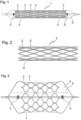
- Figure 1 shows a side view of an embodiment of the invention that has been crimped onto a dilatation balloon.
- the stent 1 consists of a plurality of ring elements 2 and 3 that are connected to one another by connecting elements 4. Ring elements 2 are located on the edge and each have only one neighbor, while ring elements 3 have either an edge or an inner ring element as a neighbor.
- the connecting elements 4 are connecting webs that start from the outer turning points of the ring elements and, in the case shown, run to the outer turning points of the neighboring ring element 3.
- the webs of the connecting elements 4 have perforations running in the direction of the longitudinal axis of the stent 1, which form a weakening zone that leads to a predetermined breaking point.
- the perforations continue through the adjacent parts of the webs of the ring segments 2, 3.
- the vascular support 1 is attached to a commercially available balloon 5, which can be transported to the site of use by means of a catheter and guide wire.
- Figure 2 shows the vascular support of Figure 1 in a first implanted state with slightly expanded ring segments 2, 3 and intact connecting elements 4. The dilatation balloon is removed from the vascular support 1.
- Figure 3 Finally, the vascular support of Figure 1 and 2 on a dilatation balloon 5.
- the dilatation balloon has a larger radius and can thus spread the stent 1 further until the perforation line 8, which runs parallel to the longitudinal axis of the stent 1, tears or breaks open.
- markers 6 which are arranged proximally and distally to the vascular support 1.
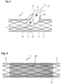
- Figure 4 shows the vascular support 1 of Figure 2 and a dilatation balloon 5 inserted therein, which has been passed laterally through the wall of the vascular support 1 and dilated. Accordingly, the predetermined breaking points of the connecting bridges the affected ring elements 2 and 3 are broken open, so that a window is created through which a branching vessel can also be supplied with blood.
- perforation lines 15 running in the longitudinal direction of the vascular support 1 as well as notches 10 which run transversely thereto through the connecting webs 4 and allow the vascular support to be separated transversely to the longitudinal direction.
- the dilatation balloon 5 at the tip of the catheter 7 is advanced over a guide wire 17 and positioned specifically into the stent 1 already implanted in the area of a vessel branch, so that the stent is broken open in the area of the branch.
- Figure 5 shows the stent of Figure 2 with a tubular membrane 19 stretched over it, which serves, for example, to shield a vascular anomaly, such as an aneurysm or a perforation.
- the membrane 19 can, for example, consist of Teflon or another biocompatible material and can optionally be equipped with a medication.
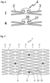
- Figure 6 shows connecting elements 4 according to the invention between ring elements 2, 3.
- the representations j and k show embodiments according to the invention in which the stent struts are arranged in the connecting element similar to a joint connection and are connected via a connecting web. This arrangement enables the setting of defined lever effects in the connecting element when the stent is expanded.
- Illustration j shows a simple embodiment, in illustration k a bending point 27 on the two-dimensional joint ball 26 is specified by the special arrangement.
- Figure 7 shows an embodiment of a vascular support 1 according to the invention in the spread-out state with a partial surface within which the connecting elements 4 between ring elements 3 are provided with predetermined breaking points.
- the zone intended for fenestration is delimited by four markers 6. Between these markers 6 all connecting elements 4 are provided with a Predetermined breaking point through perforation holes 15 arranged in a row in the longitudinal direction and with notches for generating a predetermined breaking point in the circumferential direction. When a catheter balloon expands in the area of this fenestration zone, the connecting elements 4 tear along the predetermined breaking points and open the window, for example into a side vessel.
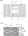
- Figure 8 shows a vascular support 1 according to the invention with webs 13 that are greatly extended in the central area in order to enable improved side branch access in the dilated state.
- the stent 1 can be split lengthwise along the dividing line 8, with the connecting elements 4 having two openings along this dividing line that bring about the weakening required for the splitting.
- Figure 9a /b shows a vascular support according to the invention with a covering 19 and predetermined breaking points in the connecting elements 4, which run both in the longitudinal direction and transversely thereto.
- the stent 1 has a ring element 2', which is connected to the peripheral ring element 2 of the stent 1 via connecting webs 4' and can be folded back onto the membrane 19.
- Fastening pins 24 serve to fix the membrane 19.
- Figure 10a /b shows a variant of the embodiment of Figure 9a /b, in which the end ring segment 2' is connected to the edge ring segments 2 via laterally offset connecting elements 4'.
- the diagonally extending connecting elements 4' facilitate the folding of the ring element 2' onto the membrane 19.
- inventions according to Figure 9 such as 10 have the predetermined breaking points according to the invention on the connecting elements 4 in the part of the stent 1 located under the membrane 19.
- FIG 11 shows in variants a to p a number of clamping elements 21 which serve to fix a membrane.
- the clamping elements 21 are webs which are notched out of a connecting element 4 or a ring element 2, 3 and which are resiliently movable against the connecting element or ring element. The membrane can thus be pushed under this resilient clamping element 21 and thereby fixed.
- the clamping elements 21 can advantageously be released from the connecting element 4 as well as from a ring element 2 or 3. These are freely movable webs of almost any shape. A widened end in the form of a star, hammer head or disk, a toothing or spikes serve to better secure a membrane.
- the clamping elements 21 can occur in pairs and run essentially in the longitudinal direction of the vascular support. In each case, a membrane is fixed by pushing it between the grid structure of the stent and the freely movable webs of the clamping elements 21, see Figure 12q.
- Figure 12 shows a vascular support 1 with a stent structure typical for heart valves with peripheral ring segments 2, adjacent ring segments 3 and connecting bars 4. Connecting bars are often designed as straight bars that run over the entire length of the stent 1 and thus define its length.
- connecting elements 34 are arranged in the area of the fracture lines 8 between the webs of the ring elements 2 and 3.
- the predetermined breaking points are formed by perforation lines that tear open during subsequent dilation and thus allow the valve to adapt to the growing vessels.
- the Figure 12 The stent 1 shown has resilient webs 21 which are suitable for fixing a heart valve-bearing stent in the surrounding vessel wall and thus prevent the stent from slipping. Furthermore, this stent can also other clamping elements as in Figure 11 a to q are included so that the flap material can be clamped in. This eliminates the need for the usual gluing, wiring or sewing of the fixed or movable flap parts.
- a second cushion-like membrane can also be advantageously clamped inside and outside with suitable clamping elements 21 for sealing purposes at the lower edge of the stent 1.
- Figure 13 shows a further embodiment of a vascular support which has clamping devices for fixing a heart valve-bearing membrane.
- the clamping devices can be one of the Figure 12 shown variant or a combination of these or other clamping devices according to the invention.
- Figure 14 shows an example of how a heart valve-bearing membrane can be transformed into a vascular support, as in Figure 14 shown, is trapped.
- Figure 15 shows a further embodiment of a vascular support which, in addition to clamping devices for fixing a heart valve-supporting membrane, has further clamping devices for receiving a further membrane lying on the outside of the vascular support.
Landscapes
- Health & Medical Sciences (AREA)
- Biomedical Technology (AREA)
- Engineering & Computer Science (AREA)
- Cardiology (AREA)
- Heart & Thoracic Surgery (AREA)
- Veterinary Medicine (AREA)
- Oral & Maxillofacial Surgery (AREA)
- Transplantation (AREA)
- Public Health (AREA)
- Vascular Medicine (AREA)
- Life Sciences & Earth Sciences (AREA)
- Animal Behavior & Ethology (AREA)
- General Health & Medical Sciences (AREA)
- Physics & Mathematics (AREA)
- Optics & Photonics (AREA)
- Prostheses (AREA)
- Media Introduction/Drainage Providing Device (AREA)
- Surgical Instruments (AREA)
Priority Applications (1)
| Application Number | Priority Date | Filing Date | Title |
|---|---|---|---|
| EP24189545.7A EP4454607A3 (de) | 2015-06-03 | 2016-06-03 | Gefässstütze |
Applications Claiming Priority (2)
| Application Number | Priority Date | Filing Date | Title |
|---|---|---|---|
| DE102015108835.5A DE102015108835A1 (de) | 2015-06-03 | 2015-06-03 | Gefäßstütze |
| PCT/EP2016/062684 WO2016193449A1 (de) | 2015-06-03 | 2016-06-03 | GEFÄßSTÜTZE |
Related Child Applications (1)
| Application Number | Title | Priority Date | Filing Date |
|---|---|---|---|
| EP24189545.7A Division EP4454607A3 (de) | 2015-06-03 | 2016-06-03 | Gefässstütze |
Publications (3)
| Publication Number | Publication Date |
|---|---|
| EP3302373A1 EP3302373A1 (de) | 2018-04-11 |
| EP3302373C0 EP3302373C0 (de) | 2024-08-07 |
| EP3302373B1 true EP3302373B1 (de) | 2024-08-07 |
Family
ID=56263655
Family Applications (2)
| Application Number | Title | Priority Date | Filing Date |
|---|---|---|---|
| EP16732459.9A Active EP3302373B1 (de) | 2015-06-03 | 2016-06-03 | Gefässstütze |
| EP24189545.7A Pending EP4454607A3 (de) | 2015-06-03 | 2016-06-03 | Gefässstütze |
Family Applications After (1)
| Application Number | Title | Priority Date | Filing Date |
|---|---|---|---|
| EP24189545.7A Pending EP4454607A3 (de) | 2015-06-03 | 2016-06-03 | Gefässstütze |
Country Status (7)
| Country | Link |
|---|---|
| US (1) | US10905573B2 (enExample) |
| EP (2) | EP3302373B1 (enExample) |
| JP (1) | JP7075660B2 (enExample) |
| CN (1) | CN107872968B (enExample) |
| DE (1) | DE102015108835A1 (enExample) |
| ES (1) | ES2988896T3 (enExample) |
| WO (1) | WO2016193449A1 (enExample) |
Families Citing this family (24)
| Publication number | Priority date | Publication date | Assignee | Title |
|---|---|---|---|---|
| US6878162B2 (en) | 2002-08-30 | 2005-04-12 | Edwards Lifesciences Ag | Helical stent having improved flexibility and expandability |
| US7780721B2 (en) | 2004-09-01 | 2010-08-24 | C. R. Bard, Inc. | Stent and method for manufacturing the stent |
| US9456911B2 (en) | 2006-02-14 | 2016-10-04 | Angiomed Gmbh & Co. Medizintechnik | Highly flexible stent and method of manufacture |
| DE102015115891A1 (de) * | 2015-09-21 | 2017-03-23 | Bentley Innomed Gmbh | Stent-Graft |
| US11622872B2 (en) | 2016-05-16 | 2023-04-11 | Elixir Medical Corporation | Uncaging stent |
| US12599490B2 (en) | 2017-05-25 | 2026-04-14 | Elixir Medical Corporation | Uncaging stent |
| CN112773583B (zh) * | 2017-08-11 | 2024-01-09 | 万能医药公司 | 撑开支架 |
| US11071626B2 (en) * | 2018-03-16 | 2021-07-27 | W. L. Gore & Associates, Inc. | Diametric expansion features for prosthetic valves |
| US10702407B1 (en) | 2019-02-28 | 2020-07-07 | Renata Medical, Inc. | Growth stent for congenital narrowings |
| CN121694847A (zh) | 2019-11-14 | 2026-03-20 | 爱德华兹生命科学公司 | 经导管的医疗植入物递送 |
| DE102019135453A1 (de) * | 2019-12-20 | 2021-06-24 | Malte Neuss | Mehrfachstent mit Membran |
| DE102020211175A1 (de) | 2020-09-04 | 2022-03-10 | Carl Zeiss Meditec Ag | Stent-Implantat zur Glaukom-Behandlung durch Kammerwasserdrainage aus der Vorderkammer |
| CN114469470B (zh) * | 2020-10-26 | 2023-06-02 | 元心科技(深圳)有限公司 | 支架 |
| CN113151980A (zh) * | 2021-03-19 | 2021-07-23 | 苏州大学 | Ptfe管状覆膜支架及其制备方法 |
| US12263104B2 (en) * | 2021-05-20 | 2025-04-01 | Cook Medical Technologies Llc | Self expanding stents and methods |
| WO2022245435A1 (en) * | 2021-05-20 | 2022-11-24 | Cook Medical Technologies Llc | Self expanding stent and method of loading same into a catheter |
| CN115363822A (zh) * | 2021-05-21 | 2022-11-22 | 爱德华兹生命科学公司 | 分流筒传感器植入物锚定 |
| CN116407335A (zh) * | 2021-12-31 | 2023-07-11 | 先健科技(深圳)有限公司 | 覆膜支架及覆膜支架输送系统 |
| ES2914516A1 (es) * | 2022-01-07 | 2022-06-13 | Conic Vascular Espana Sl | Stent pediatrico autoexpandible |
| US20230355381A1 (en) * | 2022-05-06 | 2023-11-09 | St. Jude Medical, Cardiology Division, Inc. | Detachable Cell Configuration for Valve in Valve |
| CN115192313B (zh) * | 2022-06-24 | 2024-03-26 | 柏为(武汉)医疗科技股份有限公司 | 一种可拼接外耳道支架 |
| CN115670740A (zh) * | 2022-10-10 | 2023-02-03 | 上海腾复医疗科技有限公司 | 一种血管网架结构 |
| AU2023390347A1 (en) | 2022-12-09 | 2025-06-19 | Renata Medical, Inc. | Transcatheter growth devices and methods for norwood, glenn and fontan therapy |
| CN116370168B (zh) * | 2023-05-31 | 2023-08-04 | 昆明理工大学 | 基于多圆弧星形胞元结构的血管支架结构、泊松比调节方法 |
Family Cites Families (31)
| Publication number | Priority date | Publication date | Assignee | Title |
|---|---|---|---|---|
| US5383926A (en) | 1992-11-23 | 1995-01-24 | Children's Medical Center Corporation | Re-expandable endoprosthesis |
| US7029492B1 (en) * | 1999-03-05 | 2006-04-18 | Terumo Kabushiki Kaisha | Implanting stent and dilating device |
| JP4799738B2 (ja) * | 1999-05-19 | 2011-10-26 | ノイス,マルテ | 放射状に拡大可能な管支持物 |
| US6458153B1 (en) * | 1999-12-31 | 2002-10-01 | Abps Venture One, Ltd. | Endoluminal cardiac and venous valve prostheses and methods of manufacture and delivery thereof |
| JP2003525691A (ja) * | 2000-03-09 | 2003-09-02 | ディセーニョ・イ・デサロリョ・メディコ・ソシエダッド・アノニマ・デ・カピタル・バリアブレ | カバーコネクタ付きステント |
| US8034097B2 (en) * | 2000-05-22 | 2011-10-11 | Malte Neuss | Radially expandable vessel support |
| DE10103000B4 (de) | 2001-01-24 | 2007-08-30 | Qualimed Innovative Medizinprodukte Gmbh | Radial reexpandierbare Gefäßstütze |
| US7550004B2 (en) * | 2002-08-20 | 2009-06-23 | Cook Biotech Incorporated | Endoluminal device with extracellular matrix material and methods |
| US7875068B2 (en) * | 2002-11-05 | 2011-01-25 | Merit Medical Systems, Inc. | Removable biliary stent |
| US20070219613A1 (en) * | 2003-10-06 | 2007-09-20 | Xtent, Inc. | Apparatus and methods for interlocking stent segments |
| US20050182479A1 (en) * | 2004-02-13 | 2005-08-18 | Craig Bonsignore | Connector members for stents |
| FR2881946B1 (fr) * | 2005-02-17 | 2008-01-04 | Jacques Seguin | Dispositif permettant le traitement de conduits corporels au niveau d'une bifurcation |
| US20060248698A1 (en) * | 2005-05-05 | 2006-11-09 | Hanson Brian J | Tubular stent and methods of making the same |
| US8652192B2 (en) * | 2006-03-31 | 2014-02-18 | St. Jude Medical, Cardiology Division, Inc. | Stent and system and method for deploying a stent |
| EP1958597A1 (de) * | 2007-02-16 | 2008-08-20 | Universität Zürich | Rohrförmige Stützprothese mit Herzklappe insbesondere für Aortenklappenersatz |
| US8617237B2 (en) * | 2007-02-16 | 2013-12-31 | Universität Zürich | Tubular supporting prosthesis with a heart valve, in particular for aortic valve replacement |
| EP1958598A1 (de) * | 2007-02-16 | 2008-08-20 | Universität Zürich | Wachstumsfähige, rohrförmige Stützprothese |
| DE102007019703A1 (de) | 2007-04-26 | 2008-10-30 | Biotronik Vi Patent Ag | Stent |
| US20090099651A1 (en) * | 2007-10-10 | 2009-04-16 | Miv Therapeutics, Inc. | Lipid coatings for implantable medical devices |
| EP2355755B1 (en) * | 2008-09-15 | 2017-10-18 | Abbott Laboratories Vascular Enterprises Limited | Stent with independent stent rings and transitional attachments |
| US20130238086A1 (en) * | 2009-01-16 | 2013-09-12 | Zeus Industrial Products, Inc. | Electrospun PTFE Encapsulated Stent & Method of Manufature |
| US8221489B2 (en) * | 2009-08-20 | 2012-07-17 | Stentys | Device and method for treating a body lumen |
| DE202009012562U1 (de) * | 2009-09-16 | 2009-12-17 | Bentley Surgical Gmbh | Stent mit Dehnelementen |
| BR112012008334B8 (pt) | 2009-09-16 | 2021-06-22 | Bentley Innomed Gmbh | implante médico para dilatação e sustentação de um vaso do corpo a partir de seu lado interno |
| DE102011115902B4 (de) * | 2010-12-22 | 2021-07-01 | Bentley Innomed Gmbh | Stent-Graft und dessen Verwendung |
| US10166128B2 (en) * | 2011-01-14 | 2019-01-01 | W. L. Gore & Associates. Inc. | Lattice |
| US8974521B2 (en) * | 2011-02-24 | 2015-03-10 | Biotronik Ag | Implant and method for manufacturing same |
| DE102012001996A1 (de) * | 2012-02-03 | 2013-08-08 | Bentley Surgical Gmbh | Stent-Graft III |
| WO2014004746A2 (en) * | 2012-06-26 | 2014-01-03 | Harvard Bioscience, Inc. | Methods and compositions for promoting the structural integrity of scaffolds for tissue engineering |
| CN203029427U (zh) * | 2012-12-07 | 2013-07-03 | 佳木斯大学 | 一种冠脉支架 |
| US9345597B2 (en) * | 2013-07-09 | 2016-05-24 | Abbott Cardiovascular Systems Inc. | Polymeric stent with structural radiopaque marker |
-
2015
- 2015-06-03 DE DE102015108835.5A patent/DE102015108835A1/de active Pending
-
2016
- 2016-06-03 ES ES16732459T patent/ES2988896T3/es active Active
- 2016-06-03 WO PCT/EP2016/062684 patent/WO2016193449A1/de not_active Ceased
- 2016-06-03 CN CN201680038131.6A patent/CN107872968B/zh active Active
- 2016-06-03 EP EP16732459.9A patent/EP3302373B1/de active Active
- 2016-06-03 US US15/579,009 patent/US10905573B2/en active Active
- 2016-06-03 EP EP24189545.7A patent/EP4454607A3/de active Pending
- 2016-06-03 JP JP2018515352A patent/JP7075660B2/ja active Active
Also Published As
| Publication number | Publication date |
|---|---|
| CN107872968B (zh) | 2021-04-30 |
| WO2016193449A1 (de) | 2016-12-08 |
| EP3302373C0 (de) | 2024-08-07 |
| US20180140444A1 (en) | 2018-05-24 |
| EP4454607A2 (de) | 2024-10-30 |
| EP4454607A3 (de) | 2024-12-04 |
| EP3302373A1 (de) | 2018-04-11 |
| US10905573B2 (en) | 2021-02-02 |
| ES2988896T3 (es) | 2024-11-22 |
| JP7075660B2 (ja) | 2022-05-26 |
| CN107872968A (zh) | 2018-04-03 |
| JP2018516735A (ja) | 2018-06-28 |
| DE102015108835A1 (de) | 2016-12-08 |
Similar Documents
| Publication | Publication Date | Title |
|---|---|---|
| EP3302373B1 (de) | Gefässstütze | |
| DE10103000B4 (de) | Radial reexpandierbare Gefäßstütze | |
| DE102009060228B4 (de) | Medizinische Vorrichtungen | |
| EP2259728B1 (de) | Vorrichtung zum verschluss von defekten im gefässsystem | |
| EP3528748B1 (de) | Intraluminale gefaessprothese zur implantation in das herz oder herzgefaesse eines patienten | |
| EP2117476B1 (de) | Rohrförmige stützprothese mit herzklappe insbesondere für aortenklappenersatz | |
| EP2887887B1 (de) | Implantat | |
| DE69633824T2 (de) | Vorrichtung zur implantierung in einem blutgefäss beziehungsweise in einem hohlen körperlumen | |
| DE69530159T2 (de) | Intravaskulärer Stent zur Befestigung einer Prothese | |
| DE60309843T2 (de) | Vorrichtung zur verankerung von endoluminalprothesen | |
| DE602004012037T2 (de) | Abdeckvorrichtung für einen Aneurysemhals | |
| EP2809265B1 (de) | Modularer stentgraft | |
| EP3389511B1 (de) | Implantat | |
| WO2008040555A2 (de) | Implantierbare einrichtung | |
| WO2001089414A1 (de) | Radial expandierbare gefässstütze | |
| DE102012107175B4 (de) | Medizinische Verschlussvorrichtung und System mit einer derartigen Verschlussvorrichtung | |
| DE102004045994A1 (de) | Stent zur Implantation in oder um ein Hohlorgan mit Markerelementen aus einem röntgenopaken Material | |
| DE202004014789U1 (de) | Stent zur Implantation in oder um ein Hohlorgan mit Markerelementen aus einem röntgenopaken Material | |
| EP2846731B1 (de) | Intraluminale gefässprothese mit in-situ-fenestrierung | |
| EP3412250B1 (de) | Intraluminale gefässprothese mit in-situ-fenestrierung | |
| EP2822514B1 (de) | Gefässstütze hoher flexibilität mit sollbruchstelle | |
| EP4169488A1 (de) | Stent | |
| EP1958597A1 (de) | Rohrförmige Stützprothese mit Herzklappe insbesondere für Aortenklappenersatz | |
| EP4169489A1 (de) | Stent | |
| DE69633134T2 (de) | Expandierbarer, biegbarer stent für chirurgische verwendung zum ausdehnen eines körperlumens |
Legal Events
| Date | Code | Title | Description |
|---|---|---|---|
| STAA | Information on the status of an ep patent application or granted ep patent |
Free format text: STATUS: THE INTERNATIONAL PUBLICATION HAS BEEN MADE |
|
| PUAI | Public reference made under article 153(3) epc to a published international application that has entered the european phase |
Free format text: ORIGINAL CODE: 0009012 |
|
| STAA | Information on the status of an ep patent application or granted ep patent |
Free format text: STATUS: REQUEST FOR EXAMINATION WAS MADE |
|
| 17P | Request for examination filed |
Effective date: 20180103 |
|
| AK | Designated contracting states |
Kind code of ref document: A1 Designated state(s): AL AT BE BG CH CY CZ DE DK EE ES FI FR GB GR HR HU IE IS IT LI LT LU LV MC MK MT NL NO PL PT RO RS SE SI SK SM TR |
|
| AX | Request for extension of the european patent |
Extension state: BA ME |
|
| DAV | Request for validation of the european patent (deleted) | ||
| DAX | Request for extension of the european patent (deleted) | ||
| STAA | Information on the status of an ep patent application or granted ep patent |
Free format text: STATUS: EXAMINATION IS IN PROGRESS |
|
| 17Q | First examination report despatched |
Effective date: 20230622 |
|
| GRAP | Despatch of communication of intention to grant a patent |
Free format text: ORIGINAL CODE: EPIDOSNIGR1 |
|
| STAA | Information on the status of an ep patent application or granted ep patent |
Free format text: STATUS: GRANT OF PATENT IS INTENDED |
|
| INTG | Intention to grant announced |
Effective date: 20240304 |
|
| GRAS | Grant fee paid |
Free format text: ORIGINAL CODE: EPIDOSNIGR3 |
|
| GRAA | (expected) grant |
Free format text: ORIGINAL CODE: 0009210 |
|
| STAA | Information on the status of an ep patent application or granted ep patent |
Free format text: STATUS: THE PATENT HAS BEEN GRANTED |
|
| AK | Designated contracting states |
Kind code of ref document: B1 Designated state(s): AL AT BE BG CH CY CZ DE DK EE ES FI FR GB GR HR HU IE IS IT LI LT LU LV MC MK MT NL NO PL PT RO RS SE SI SK SM TR |
|
| REG | Reference to a national code |
Ref country code: GB Ref legal event code: FG4D Free format text: NOT ENGLISH |
|
| REG | Reference to a national code |
Ref country code: CH Ref legal event code: EP |
|
| REG | Reference to a national code |
Ref country code: DE Ref legal event code: R096 Ref document number: 502016016662 Country of ref document: DE |
|
| REG | Reference to a national code |
Ref country code: IE Ref legal event code: FG4D Free format text: LANGUAGE OF EP DOCUMENT: GERMAN |
|
| U01 | Request for unitary effect filed |
Effective date: 20240903 |
|
| U07 | Unitary effect registered |
Designated state(s): AT BE BG DE DK EE FI FR IT LT LU LV MT NL PT RO SE SI Effective date: 20240916 |
|
| REG | Reference to a national code |
Ref country code: ES Ref legal event code: FG2A Ref document number: 2988896 Country of ref document: ES Kind code of ref document: T3 Effective date: 20241122 |
|
| PG25 | Lapsed in a contracting state [announced via postgrant information from national office to epo] |
Ref country code: NO Free format text: LAPSE BECAUSE OF FAILURE TO SUBMIT A TRANSLATION OF THE DESCRIPTION OR TO PAY THE FEE WITHIN THE PRESCRIBED TIME-LIMIT Effective date: 20241107 |
|
| PG25 | Lapsed in a contracting state [announced via postgrant information from national office to epo] |
Ref country code: PL Free format text: LAPSE BECAUSE OF FAILURE TO SUBMIT A TRANSLATION OF THE DESCRIPTION OR TO PAY THE FEE WITHIN THE PRESCRIBED TIME-LIMIT Effective date: 20240807 Ref country code: GR Free format text: LAPSE BECAUSE OF FAILURE TO SUBMIT A TRANSLATION OF THE DESCRIPTION OR TO PAY THE FEE WITHIN THE PRESCRIBED TIME-LIMIT Effective date: 20241108 |
|
| PG25 | Lapsed in a contracting state [announced via postgrant information from national office to epo] |
Ref country code: IS Free format text: LAPSE BECAUSE OF FAILURE TO SUBMIT A TRANSLATION OF THE DESCRIPTION OR TO PAY THE FEE WITHIN THE PRESCRIBED TIME-LIMIT Effective date: 20241207 |
|
| PG25 | Lapsed in a contracting state [announced via postgrant information from national office to epo] |
Ref country code: HR Free format text: LAPSE BECAUSE OF FAILURE TO SUBMIT A TRANSLATION OF THE DESCRIPTION OR TO PAY THE FEE WITHIN THE PRESCRIBED TIME-LIMIT Effective date: 20240807 |
|
| PG25 | Lapsed in a contracting state [announced via postgrant information from national office to epo] |
Ref country code: RS Free format text: LAPSE BECAUSE OF FAILURE TO SUBMIT A TRANSLATION OF THE DESCRIPTION OR TO PAY THE FEE WITHIN THE PRESCRIBED TIME-LIMIT Effective date: 20241107 |
|
| PG25 | Lapsed in a contracting state [announced via postgrant information from national office to epo] |
Ref country code: RS Free format text: LAPSE BECAUSE OF FAILURE TO SUBMIT A TRANSLATION OF THE DESCRIPTION OR TO PAY THE FEE WITHIN THE PRESCRIBED TIME-LIMIT Effective date: 20241107 Ref country code: PL Free format text: LAPSE BECAUSE OF FAILURE TO SUBMIT A TRANSLATION OF THE DESCRIPTION OR TO PAY THE FEE WITHIN THE PRESCRIBED TIME-LIMIT Effective date: 20240807 Ref country code: NO Free format text: LAPSE BECAUSE OF FAILURE TO SUBMIT A TRANSLATION OF THE DESCRIPTION OR TO PAY THE FEE WITHIN THE PRESCRIBED TIME-LIMIT Effective date: 20241107 Ref country code: IS Free format text: LAPSE BECAUSE OF FAILURE TO SUBMIT A TRANSLATION OF THE DESCRIPTION OR TO PAY THE FEE WITHIN THE PRESCRIBED TIME-LIMIT Effective date: 20241207 Ref country code: HR Free format text: LAPSE BECAUSE OF FAILURE TO SUBMIT A TRANSLATION OF THE DESCRIPTION OR TO PAY THE FEE WITHIN THE PRESCRIBED TIME-LIMIT Effective date: 20240807 Ref country code: GR Free format text: LAPSE BECAUSE OF FAILURE TO SUBMIT A TRANSLATION OF THE DESCRIPTION OR TO PAY THE FEE WITHIN THE PRESCRIBED TIME-LIMIT Effective date: 20241108 |
|
| PG25 | Lapsed in a contracting state [announced via postgrant information from national office to epo] |
Ref country code: SM Free format text: LAPSE BECAUSE OF FAILURE TO SUBMIT A TRANSLATION OF THE DESCRIPTION OR TO PAY THE FEE WITHIN THE PRESCRIBED TIME-LIMIT Effective date: 20240807 |
|
| PG25 | Lapsed in a contracting state [announced via postgrant information from national office to epo] |
Ref country code: CZ Free format text: LAPSE BECAUSE OF FAILURE TO SUBMIT A TRANSLATION OF THE DESCRIPTION OR TO PAY THE FEE WITHIN THE PRESCRIBED TIME-LIMIT Effective date: 20240807 |
|
| PG25 | Lapsed in a contracting state [announced via postgrant information from national office to epo] |
Ref country code: SK Free format text: LAPSE BECAUSE OF FAILURE TO SUBMIT A TRANSLATION OF THE DESCRIPTION OR TO PAY THE FEE WITHIN THE PRESCRIBED TIME-LIMIT Effective date: 20240807 |
|
| PLBE | No opposition filed within time limit |
Free format text: ORIGINAL CODE: 0009261 |
|
| STAA | Information on the status of an ep patent application or granted ep patent |
Free format text: STATUS: NO OPPOSITION FILED WITHIN TIME LIMIT |
|
| PGFP | Annual fee paid to national office [announced via postgrant information from national office to epo] |
Ref country code: GB Payment date: 20250618 Year of fee payment: 10 |
|
| 26N | No opposition filed |
Effective date: 20250508 |
|
| PGFP | Annual fee paid to national office [announced via postgrant information from national office to epo] |
Ref country code: IE Payment date: 20250618 Year of fee payment: 10 |
|
| U20 | Renewal fee for the european patent with unitary effect paid |
Year of fee payment: 10 Effective date: 20250627 |
|
| PGFP | Annual fee paid to national office [announced via postgrant information from national office to epo] |
Ref country code: ES Payment date: 20250728 Year of fee payment: 10 |
|
| PGFP | Annual fee paid to national office [announced via postgrant information from national office to epo] |
Ref country code: CH Payment date: 20250701 Year of fee payment: 10 |
|
| PG25 | Lapsed in a contracting state [announced via postgrant information from national office to epo] |
Ref country code: MC Free format text: LAPSE BECAUSE OF FAILURE TO SUBMIT A TRANSLATION OF THE DESCRIPTION OR TO PAY THE FEE WITHIN THE PRESCRIBED TIME-LIMIT Effective date: 20240807 |