EP3301281A2 - Startsteuerungsvorrichtung für sattelfahrzeug - Google Patents
Startsteuerungsvorrichtung für sattelfahrzeug Download PDFInfo
- Publication number
- EP3301281A2 EP3301281A2 EP17191531.7A EP17191531A EP3301281A2 EP 3301281 A2 EP3301281 A2 EP 3301281A2 EP 17191531 A EP17191531 A EP 17191531A EP 3301281 A2 EP3301281 A2 EP 3301281A2
- Authority
- EP
- European Patent Office
- Prior art keywords
- start control
- upper limit
- limit value
- engine
- mode
- Prior art date
- Legal status (The legal status is an assumption and is not a legal conclusion. Google has not performed a legal analysis and makes no representation as to the accuracy of the status listed.)
- Withdrawn
Links
Images


Classifications
-
- B—PERFORMING OPERATIONS; TRANSPORTING
- B60—VEHICLES IN GENERAL
- B60K—ARRANGEMENT OR MOUNTING OF PROPULSION UNITS OR OF TRANSMISSIONS IN VEHICLES; ARRANGEMENT OR MOUNTING OF PLURAL DIVERSE PRIME-MOVERS IN VEHICLES; AUXILIARY DRIVES FOR VEHICLES; INSTRUMENTATION OR DASHBOARDS FOR VEHICLES; ARRANGEMENTS IN CONNECTION WITH COOLING, AIR INTAKE, GAS EXHAUST OR FUEL SUPPLY OF PROPULSION UNITS IN VEHICLES
- B60K28/00—Safety devices for propulsion-unit control, specially adapted for, or arranged in, vehicles, e.g. preventing fuel supply or ignition in the event of potentially dangerous conditions
- B60K28/10—Safety devices for propulsion-unit control, specially adapted for, or arranged in, vehicles, e.g. preventing fuel supply or ignition in the event of potentially dangerous conditions responsive to conditions relating to the vehicle
- B60K28/16—Safety devices for propulsion-unit control, specially adapted for, or arranged in, vehicles, e.g. preventing fuel supply or ignition in the event of potentially dangerous conditions responsive to conditions relating to the vehicle responsive to, or preventing, spinning or skidding of wheels
-
- F—MECHANICAL ENGINEERING; LIGHTING; HEATING; WEAPONS; BLASTING
- F02—COMBUSTION ENGINES; HOT-GAS OR COMBUSTION-PRODUCT ENGINE PLANTS
- F02D—CONTROLLING COMBUSTION ENGINES
- F02D41/00—Electrical control of supply of combustible mixture or its constituents
- F02D41/02—Circuit arrangements for generating control signals
- F02D41/021—Introducing corrections for particular conditions exterior to the engine
- F02D41/0215—Introducing corrections for particular conditions exterior to the engine in relation with elements of the transmission
- F02D41/0225—Introducing corrections for particular conditions exterior to the engine in relation with elements of the transmission in relation with the gear ratio or shift lever position
-
- A—HUMAN NECESSITIES
- A63—SPORTS; GAMES; AMUSEMENTS
- A63K—RACING; RIDING SPORTS; EQUIPMENT OR ACCESSORIES THEREFOR
- A63K3/00—Equipment or accessories for racing or riding sports
- A63K3/02—Starting-appliances
-
- F—MECHANICAL ENGINEERING; LIGHTING; HEATING; WEAPONS; BLASTING
- F02—COMBUSTION ENGINES; HOT-GAS OR COMBUSTION-PRODUCT ENGINE PLANTS
- F02B—INTERNAL-COMBUSTION PISTON ENGINES; COMBUSTION ENGINES IN GENERAL
- F02B61/00—Adaptations of engines for driving vehicles or for driving propellers; Combinations of engines with gearing
- F02B61/02—Adaptations of engines for driving vehicles or for driving propellers; Combinations of engines with gearing for driving cycles
-
- F—MECHANICAL ENGINEERING; LIGHTING; HEATING; WEAPONS; BLASTING
- F02—COMBUSTION ENGINES; HOT-GAS OR COMBUSTION-PRODUCT ENGINE PLANTS
- F02D—CONTROLLING COMBUSTION ENGINES
- F02D31/00—Use of speed-sensing governors to control combustion engines, not otherwise provided for
- F02D31/001—Electric control of rotation speed
- F02D31/002—Electric control of rotation speed controlling air supply
- F02D31/006—Electric control of rotation speed controlling air supply for maximum speed control
-
- F—MECHANICAL ENGINEERING; LIGHTING; HEATING; WEAPONS; BLASTING
- F02—COMBUSTION ENGINES; HOT-GAS OR COMBUSTION-PRODUCT ENGINE PLANTS
- F02D—CONTROLLING COMBUSTION ENGINES
- F02D31/00—Use of speed-sensing governors to control combustion engines, not otherwise provided for
- F02D31/001—Electric control of rotation speed
- F02D31/007—Electric control of rotation speed controlling fuel supply
- F02D31/009—Electric control of rotation speed controlling fuel supply for maximum speed control
-
- F—MECHANICAL ENGINEERING; LIGHTING; HEATING; WEAPONS; BLASTING
- F02—COMBUSTION ENGINES; HOT-GAS OR COMBUSTION-PRODUCT ENGINE PLANTS
- F02D—CONTROLLING COMBUSTION ENGINES
- F02D41/00—Electrical control of supply of combustible mixture or its constituents
- F02D41/02—Circuit arrangements for generating control signals
- F02D41/021—Introducing corrections for particular conditions exterior to the engine
-
- F—MECHANICAL ENGINEERING; LIGHTING; HEATING; WEAPONS; BLASTING
- F02—COMBUSTION ENGINES; HOT-GAS OR COMBUSTION-PRODUCT ENGINE PLANTS
- F02D—CONTROLLING COMBUSTION ENGINES
- F02D41/00—Electrical control of supply of combustible mixture or its constituents
- F02D41/02—Circuit arrangements for generating control signals
- F02D41/04—Introducing corrections for particular operating conditions
- F02D41/06—Introducing corrections for particular operating conditions for engine starting or warming up
- F02D41/062—Introducing corrections for particular operating conditions for engine starting or warming up for starting
-
- F—MECHANICAL ENGINEERING; LIGHTING; HEATING; WEAPONS; BLASTING
- F02—COMBUSTION ENGINES; HOT-GAS OR COMBUSTION-PRODUCT ENGINE PLANTS
- F02D—CONTROLLING COMBUSTION ENGINES
- F02D41/00—Electrical control of supply of combustible mixture or its constituents
- F02D41/02—Circuit arrangements for generating control signals
- F02D41/04—Introducing corrections for particular operating conditions
- F02D41/10—Introducing corrections for particular operating conditions for acceleration
-
- F—MECHANICAL ENGINEERING; LIGHTING; HEATING; WEAPONS; BLASTING
- F02—COMBUSTION ENGINES; HOT-GAS OR COMBUSTION-PRODUCT ENGINE PLANTS
- F02P—IGNITION, OTHER THAN COMPRESSION IGNITION, FOR INTERNAL-COMBUSTION ENGINES; TESTING OF IGNITION TIMING IN COMPRESSION-IGNITION ENGINES
- F02P5/00—Advancing or retarding ignition; Control therefor
- F02P5/04—Advancing or retarding ignition; Control therefor automatically, as a function of the working conditions of the engine or vehicle or of the atmospheric conditions
- F02P5/045—Advancing or retarding ignition; Control therefor automatically, as a function of the working conditions of the engine or vehicle or of the atmospheric conditions combined with electronic control of other engine functions, e.g. fuel injection
-
- F—MECHANICAL ENGINEERING; LIGHTING; HEATING; WEAPONS; BLASTING
- F02—COMBUSTION ENGINES; HOT-GAS OR COMBUSTION-PRODUCT ENGINE PLANTS
- F02P—IGNITION, OTHER THAN COMPRESSION IGNITION, FOR INTERNAL-COMBUSTION ENGINES; TESTING OF IGNITION TIMING IN COMPRESSION-IGNITION ENGINES
- F02P5/00—Advancing or retarding ignition; Control therefor
- F02P5/04—Advancing or retarding ignition; Control therefor automatically, as a function of the working conditions of the engine or vehicle or of the atmospheric conditions
- F02P5/145—Advancing or retarding ignition; Control therefor automatically, as a function of the working conditions of the engine or vehicle or of the atmospheric conditions using electrical means
- F02P5/15—Digital data processing
- F02P5/1502—Digital data processing using one central computing unit
- F02P5/1506—Digital data processing using one central computing unit with particular means during starting
-
- F—MECHANICAL ENGINEERING; LIGHTING; HEATING; WEAPONS; BLASTING
- F02—COMBUSTION ENGINES; HOT-GAS OR COMBUSTION-PRODUCT ENGINE PLANTS
- F02D—CONTROLLING COMBUSTION ENGINES
- F02D2200/00—Input parameters for engine control
- F02D2200/02—Input parameters for engine control the parameters being related to the engine
- F02D2200/04—Engine intake system parameters
- F02D2200/0404—Throttle position
-
- F—MECHANICAL ENGINEERING; LIGHTING; HEATING; WEAPONS; BLASTING
- F02—COMBUSTION ENGINES; HOT-GAS OR COMBUSTION-PRODUCT ENGINE PLANTS
- F02D—CONTROLLING COMBUSTION ENGINES
- F02D2200/00—Input parameters for engine control
- F02D2200/02—Input parameters for engine control the parameters being related to the engine
- F02D2200/10—Parameters related to the engine output, e.g. engine torque or engine speed
- F02D2200/101—Engine speed
-
- F—MECHANICAL ENGINEERING; LIGHTING; HEATING; WEAPONS; BLASTING
- F02—COMBUSTION ENGINES; HOT-GAS OR COMBUSTION-PRODUCT ENGINE PLANTS
- F02D—CONTROLLING COMBUSTION ENGINES
- F02D2200/00—Input parameters for engine control
- F02D2200/50—Input parameters for engine control said parameters being related to the vehicle or its components
- F02D2200/501—Vehicle speed
-
- Y—GENERAL TAGGING OF NEW TECHNOLOGICAL DEVELOPMENTS; GENERAL TAGGING OF CROSS-SECTIONAL TECHNOLOGIES SPANNING OVER SEVERAL SECTIONS OF THE IPC; TECHNICAL SUBJECTS COVERED BY FORMER USPC CROSS-REFERENCE ART COLLECTIONS [XRACs] AND DIGESTS
- Y02—TECHNOLOGIES OR APPLICATIONS FOR MITIGATION OR ADAPTATION AGAINST CLIMATE CHANGE
- Y02T—CLIMATE CHANGE MITIGATION TECHNOLOGIES RELATED TO TRANSPORTATION
- Y02T10/00—Road transport of goods or passengers
- Y02T10/10—Internal combustion engine [ICE] based vehicles
- Y02T10/40—Engine management systems
Definitions
- the present invention relates generally to start control devices for saddled vehicles and, more particularly, to a start control device suitable for a saddled vehicle (motocrosser) for use in a motocross race in which all attending motorcycles start using starting gates.
- motocrosser a saddled vehicle
- JP 5798387 B2 discloses a technique for achieving favorable acceleration performance in a saddled vehicle regardless of the road surface condition.
- the technique disclosed in JP 5798387 B2 operates as follows. Specifically, when the current condition is determined to be before the vehicle is started, the ignition timing is controlled so that the engine speed is a target value; meanwhile, the target value is determined in accordance with a clutch operating state and, when the clutch starts slipping to cause the engine speed to decrease or otherwise fluctuate, the target value is reduced to match the fluctuation, so that the engine speed can be brought to reach the target value when the clutch is engaged and the vehicle is to be accelerated.
- a starting gate mainly includes, as exemplarily depicted in FIG. 14 , two gate bases 71 and 72, a connecting bar 73, and a U-shaped gate bar 74.
- the two gate bases 71 and 72 extend in parallel with each other on both sides of the starting gate along a vehicle starting direction.
- the connecting bar 73 connects and fixes each of the gate bases 71 and 72 on first end sides thereof.
- the U-shaped gate bar 74 is rotatably supported at the first end side of each of the gate bases 71 and 72. A rider of the motocrosser waits for the U-shaped gate bar 74 to lower before starting the motocrosser.
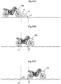
- a drive wheel (rear wheel) of the motocrosser though located on a rough road surface at starting, climbs over a starting gate 61 immediately after the starting and thereafter travels again on the rough road surface.
- the motocrosser is to accelerate while climbing over the connecting bar 73 and the lowered U-shaped gate bar 74 of the starting gate 61.
- the motocrosser can, however, exhibit only a weaker road gripping force on the respective bars 73 and 74 than on the rough road surface.
- an output that is similar in level to an output on the rough road surface is applied to the drive wheel, the drive wheel slips, resulting in degraded acceleration performance.
- the motocrosser undergoes a great change in road surface conditions when climbing over the starting gate 61 and accelerating.
- Each rider thus makes full use of sophisticated techniques in throttle operation and clutch operation on the basis of the respective riders own experience.
- the method that uniformly controls the engine output on the basis of throttle operation or clutch operation, as in the technique disclosed in Patent Document 1, cannot contribute a lot to improved acceleration performance despite its complexity.
- a start control device for a saddled vehicle changing an upper limit value of an engine speed upon start of the vehicle in accordance with a vehicle condition of the present invention is characterized by having following constitutions.
- FIG. 1 is a functional block diagram depicting a configuration of an engine control device to which start control according to an embodiment of the present invention is applied.
- FIG. 1 omits any configuration that is unnecessary for the description of the present invention.
- An engine 5 includes a cylinder 10 that, in turn, includes a cylinder head 8 disposed at an upper portion of the cylinder 10.
- the cylinder head 8 includes an intake valve IV and an exhaust valve EV
- the engine 5 further includes a crankshaft 1 on which a crank pulser rotor 2 is mounted.
- the crank pulser rotor 2 includes a rotor 3 that rotates synchronously with the crankshaft 1 and a reluctor 4.
- a magnetic pick-up type pulse generator PC is disposed to face an outer periphery of the rotor 3.
- the pulse generator PC outputs an ON signal or OFF signal of a crank pulse depending on presence of the reluctor 4.
- the crank pulse is applied to an engine control unit (ECU) 50.
- ECU engine control unit
- An airflow sensor 15, a throttle opening sensor 14, and an intake pressure sensor 17 are mounted in an intake pipe 11.
- the airflow sensor 15 measures an intake air amount.
- the throttle opening sensor 14 outputs a signal that corresponds to an opening of a throttle valve 13 (throttle opening).
- the intake pressure sensor 17 detects intake pressure.
- a temperature sensor 16 that detects a temperature of the engine 5 is mounted on the cylinder 10.
- An ignition device 9 is disposed at an upper portion of a combustion chamber.
- a fuel injection device 12 is disposed downstream of the throttle valve 13 in the intake pipe 11.
- An oxygen concentration sensor 7 is mounted on an exhaust pipe 6.
- a piezoelectric element type cylinder pressure sensor for example, may be disposed on the ignition device 9.
- the ECU 50 includes a start control unit 25 and an ignition control unit 26.
- the start control unit 25 initiates start control on condition that at least a start mode switch 28 being operated to be turned ON.
- the start control unit 25 then performs the start control with reference to, for example, a function selection switch 29.
- the start mode switch 28 and the function selection switch 29 will be described in detail later.
- the ignition control unit 26 prohibits ignition of the engine in response to an ignition prohibition command from the start control unit 25.
- a throttle opening detection module 501 detects the throttle opening on the basis of an output from the throttle opening sensor 14.
- a vehicle speed detection module 502 detects a vehicle speed on the basis of an output from a vehicle speed sensor 30.
- An engine speed detection module 503 detects an engine speed on the basis of a crank pulse.
- An engine load detection module 504 detects presence of an engine load.
- a timer function module 505 measures various types of elapsed period of time.
- a switch detection module 506 detects an open or closed state of various types of switches including the start mode switch 28 and the function selection switch 29.
- An operating mode determination module 507 determines an operating mode during the start control.
- An upper limit speed setting module 508 sets an upper limit value of the engine speed in accordance with the operating mode.
- a speed limiting module 509 outputs an ignition prohibition command to the ignition control unit 26 so that the engine speed is limited to the upper limit value (NErev0, NErev1 or NErev2) in accordance with each operating mode.
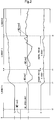
- FIG. 2 is a timing chart of the start control in which the operating mode determination module 507 establishes the operating mode in accordance with vehicle behavior upon start of the vehicle and the upper limit speed setting module 508 sets the upper limit value of the engine speed in accordance with the established operating mode.
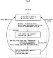
- FIG. 3 is a state transition diagram of each operating mode in the start control.
- the ordinary mode non-start control
- the upper limit value of the engine speed NE is set to an engine upper limit value NErev0 that depends on engine specifications.
- An engine ignition timing and a fuel injection amount are then controlled to thereby limit the engine speed to the upper limit value NErev0.
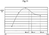
- the upper limit value of the engine speed NE is set to a start standby upper limit value (a first upper limit value) NErev1 that, as depicted in FIG. 11 , falls within a speed range just after a peak in engine output and that is slightly lower than the engine upper limit value NErev0.
- the upper limit value NErev1 is set to a value that can limit an output characteristic ( FIG. 11 ) dependent on the engine speed NE to a range in which traction of the drive wheel is not lost.
- the speed limiting module 509 instructs the ignition control unit 26 to prohibit ignition of the engine such that the upper limit value of the engine speed NE is limited to the first upper limit value NErev1.
- ignition prohibition control is initiated when the engine speed detection module 503 detects that the engine speed has reached a predetermined upper limit value Nrev.
- Nrev a predetermined upper limit value
- crank mass inertia may cause an overshoot to occur beyond the upper limit value Nrev.
- a slight overshoot occurs in a period before time t4.
- the predetermined standby period of time e.g., 0.1 second
- the changeover may be made at a mild pace by gradually increasing the upper limit value at a predetermined rate from time t4 as indicated by the broken line in FIG. 2 .
- the upper limit value of the engine speed NE is set to the starting gate climb-over upper limit value (a second upper limit value) NErev2 that falls within the speed range just after the peak in the engine output and that is even lower than the start standby upper limit value NErev1.
- the upper limit value NErev2 is set to a value that can limit the output characteristic ( FIG. 11 ) dependent on the engine speed NE to a range in which traction of the rear wheel is not lost.
- the speed limiting module 509 instructs the ignition control unit 26 to prohibit ignition of the engine such that the upper limit value of the engine speed NE is limited to the second upper limit value NErev2.
- the elapsed period of time after the transition to the gate climb-over mode is equal to or longer than a predetermined control period of time (0.55 second in the present embodiment) and when a timing is reached at which the drive wheel can be determined to have climbed over the connecting bar 73 and the U-shaped gate bar 74 of the starting gate 61 as depicted in FIG. 10c , the operating mode transitions to the ordinary mode and the upper limit value of the engine speed is set to the engine upper limit value NErev0. The start control is thereby terminated.
- the operating mode transitions to the ordinary mode at time t4 at which the control period of time corresponding to the passage of the gate is determined to have elapsed.
- the speed limiting module 509 controls the ignition timing and the fuel injection amount such that the upper limit value of the engine speed NE is limited to the engine upper limit value NErev0.
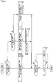
- FIG. 4 is a flowchart depicting steps to be followed in the start control in the present invention, in which the operating mode determination module 507 establishes the operating mode and the upper limit speed setting module 508 dynamically changes the upper limit value of the engine speed in accordance with the established operating mode.
- FIG. 5 is a flowchart depicting steps to be followed to determine whether or not the operating mode transition is enabled in Step S9.
- the gear position in the second speed or the first speed is determined to fall within the range that enables transition and Step S103 is then performed. If initiation of the start control is based on condition that the gear position is the second speed or lower as described above, erroneous transition to engine speed control unique to the start mode can be prevented from occurring even when the start mode switch is mistakenly operated during traveling.
- Step S101 if it is determined in Step S101 that the engine speed NE falls outside the range that enables transition to the start standby mode or if it is determined in Step S102 that the current gear position falls outside the range that enables transition to the start standby mode (specifically, the gear position is the third speed or higher), or if it is determined in Step S103 that the start mode switch 28 is not turned ON continuously for the predetermined period of time or longer, then Step S106 is performed.
- the start control is terminated when the gear position in the third speed or higher is detected during the start control. Inconvenience in which the start control is continuously performed unnecessarily can be prevented.
- Step S106 a default value is set in the start mode switch continuation timer tmSTRTSW and the start mode switch continuation timer tmSTRTSW starts a downward counting sequence.
- Step S107 a cancellation determination threshold C_TMENDTH is set in a start mode cancellation timer tmENDTH and the start mode cancellation timer tmENDTH starts a downward counting sequence. Additionally, a start mode cancellation command is set (specified).
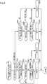
- FIG. 6 is a flowchart depicting steps to be followed to determine whether the transition from the start standby mode to the gate climb-over mode is enabled.
- Step S201 reference is made to a determination index flag F_SWSRST that determines a specific index, either the rear wheel speed or the throttle opening, to be used for determining whether or not the transition of the operating mode is to be enabled.
- Step S202 is performed to make the determination on the basis of the rear wheel speed.
- Step S202 it is determined whether or not a rear wheel speed VPLSR is equal to or higher than a predetermined threshold. If it is determined that the rear wheel speed VPLSR is equal to or higher than the threshold, Step S203 is performed and it is determined whether or not a condition in which the rear wheel speed VPLSR is equal to or higher than the threshold continues for a predetermined period of time or longer on the basis of whether or not a vehicle speed continuation timer tmVRSTWT has timed out.
- Step S205 is performed and 0.1 second as the default value is set in the vehicle speed continuation timer tmVRSTWT and the vehicle speed continuation timer tmVRSTWT starts a downward counting sequence.
- Step S207 is performed to determine whether or not the transition of the operating mode is to be enabled on the basis of the throttle opening. Then, it is determined whether or not the throttle opening TH is equal to or greater than a predetermined threshold.
- Step S208 is performed. Then, reference is made to a no-load flag Fnoload and the current engine load condition is determined.
- the engine load condition is determined on the basis of whether or not a transmission is in a neutral position. Specifically, the engine is determined to be in a no-load condition when a neutral switch that detects that the transmission is in the neutral position is ON. The engine is determined to be in any condition other than the no-load condition when the neutral switch is OFF and the transmission is in gear.
- Step S209 is performed. It is then determined whether or not a throttle open continuation timer tmTHSTWT has timed out. If it is determined that the throttle open continuation timer tmTHSTWT has timed out, it is then determined that the condition in which the throttle opening TH is equal to or greater than the predetermined threshold continues for a predetermined period of time or longer. Then, Step S210 is performed and the operating mode transitions to the gate climb-over mode.
- Step S211 is performed and 0.1 second as the default value is set in the throttle open continuation timer tmTHSTWT and the throttle open continuation timer tmTHSTWT starts a downward counting sequence.
- Step S7 it is determined whether or not transition from the gate climb-over mode to another operating mode is to be enabled.
- Step S303 a count value equivalent to 10 ms is added to the elapsed period of time TMAFTLANC.
- Step S8 a "start mode cancellation determination" is made.
- FIG. 8 is a flowchart depicting steps to be followed in the "start mode cancellation determination.”
- Step S403 it is determined whether or not the vehicle speed sensor 30 is determined to have failed. If it is determined that the vehicle speed sensor 30 is determined to have failed, Step S405 is performed and a start mode cancellation command flag F_MDSTDS is set (specified). In contrast, if it is determined that the vehicle speed sensor 30 is determined to have not failed, Step S404 is performed and a "forced cancellation condition selection process" to be described later is performed.
- FIG. 9 is a flowchart depicting steps of the forced cancellation condition selection process performed in Step S404.
- Step S501 reference is made to the function selection switch 29 that selects, as a forced cancellation determination condition, either an OR condition that requires holding of either the gear position or the throttle opening, or an AND condition that requires holding of both the gear position and the throttle opening.
- Step S502 is performed and it is determined whether or not the current gear position is a forced cancellation position or higher. If it is determined that the current gear position is the forced cancellation position or higher, Step S505 is performed and the start mode cancellation command flag F_MDSTDS is set.
- Step S504 is performed and it is determined whether or not the cancellation condition by the throttle opening holds on the basis of whether or not the start mode cancellation timer tmENDTH has timed out and whether or not the forced cancellation on the basis of the throttle opening has been enabled.
- Step S505 is performed and the start mode cancellation command flag F_MDSTDS is set.
- Step S506 is performed and the start mode cancellation command flag F_MDSTDS is reset.
- Step S507 is performed and it is determined whether or not the current gear position is the forced cancellation position or higher. If it is determined that the current gear position is not the forced cancellation position or higher, Step S511 is performed and the start mode cancellation command flag F_MDSTDS is reset.
- Step S509 is performed and it is determined whether or not the cancellation condition by the throttle opening holds on the basis of whether or not the start mode cancellation timer tmENDTH has timed out and whether or not the forced cancellation on the basis of the throttle opening has been enabled.
- Step S510 the start mode cancellation command flag F_MDSTDS is set.
- Step S511 the start mode cancellation command flag F_MDSTDS is reset.
- the start control that prevents the drive wheel from slipping upon starting to thereby improve acceleration performance can be achieved using a simple system that uses as parameters only the throttle opening and the elapsed period of time.
- the upper limit value of the engine speed is limited to the first upper limit value for the period of time during which the drive wheel that remains a stationary state reaches the connecting bar 73 of the starting gate 61. This arrangement prevents the drive wheel from slipping on rough road surfaces, enabling the vehicle to exhibit favorable acceleration performance.
- the upper limit value of the engine speed is limited to the second upper limit value that is even lower than the first upper limit value. This arrangement prevents the drive wheel from slipping when climbing over the gate bar that has ⁇ even lower than ⁇ of rough road surfaces, so that the vehicle can exhibit favorable acceleration performance.
- the ignition of the engine and the fuel injection amount are limited such that the engine speed does not exceed the upper limit value in the non-start control.
- the control can quickly transition to output control optimized for types of driving the motocrosser is assumed to undergo.
- the ignition control unit prohibits the ignition of the engine when the engine speed exceeds the upper limit value in each of the operating modes.
- aAs compared with a case in which the upper limit value of the engine speed is limited by fuel cut, response and follow-up performance of the engine speed can be improved when an operation is detected to increase the engine speed after the start control has been terminated.
- the start control unit terminates the start control when the throttle opening is less than a predetermined threshold during the start control.
- the start control can be terminated on the basis of a vehicle operation performed by the rider.
- the first upper limit value and the second upper limit value of the engine speed are higher than a speed at which an engine output characteristic exhibits a peak.
- FIGS. 12 and 13 are illustrations depicting methods of mounting the start mode switch 28 on a motocrosser that includes the start control device according to the present invention.
- FIG. 12 illustrates exemplary mounting of the start mode switch 28 in an area near a right grip.
- FIG. 13 illustrates exemplary mounting of the start mode switch 28 in an area near a left grip.
- a handlebar grip 32R is disposed on a right end portion of a handlebar pipe 31 so as to be capable of throttle operation.
- a throttle holder 33 pulls or releases two wire cables 34 in accordance with a rotational operation of the handlebar grip 32R.
- a connection between the throttle holder 33 and the wire cables 34 is covered in a rubber cover 35.
- a brake lever 36 is supported on the handlebar pipe 31 by a lever holder 37.
- a brake hose 39 is connected with a brake hose base portion 38 of the lever holder 37.
- a switch cover 41 is disposed between the throttle holder 33 and the lever holder 37.
- the switch cover 41 includes a starter switch 40 that has a function as the start mode switch 28.
- a wiring cord 42 extending from the switch cover 41 is tied onto the handlebar pipe 31 by resin bands 43 and 44.
- the switch 28/40 when the switch 28/40 is operated to be turned ON while the engine remains stationary, the switch 28/40 acts as the starter switch 40 to thereby start the engine. In contrast, when the switch 28/40 is operated to be turned ON while the engine is running, the switch 28/40 acts as the start mode switch 28, providing a requirement for initiating the start control.
- An extended portion 31a is disposed between a central mounting portion and a grip portion on either end of the handlebar pipe 31.
- the extended portion 31a has a predetermined angle relative to each of different parts.
- a cushion support bar 46 that supports a cylindrical cushion 45 is connected with the extended portion 31a via an aluminum clamp 47.
- a handlebar grip 32L is disposed on a left end portion of the handlebar pipe 31 so as not to be rotatable.
- a clutch lever 49 is supported by a lever holder 48 that is fixed to the handlebar pipe 31 at a position inside the handlebar grip 32L.
- the cylindrical cushion 45 is supported via an aluminum clamp 54 and the cushion support bar 46.
- a wire cable 50 is connected with the lever holder 48.
- An engine stop switch 51 is disposed between the handlebar grip 32L and the lever holder 48.
- the engine stop switch 51 having the function as the start mode switch 28 is tied with the handlebar pipe 31 using an appropriate tying device 55.
- a wiring cord 52 of the engine stop switch 51 is tied with the handlebar pipe 31 by a resin band 53.
- the switch 28/51 when the switch 28/51 is operated to be turned ON for less than a predetermined threshold, the switch 28/51 acts as the engine stop switch 51 to thereby bring the engine to a stop. In contrast, when the switch 28/51 is operated to be turned ON for the predetermined threshold or longer, the switch 28/51 acts as the start mode switch 28, providing a requirement for initiating the start control.
- the start mode switch is disposed near the handlebar grip of the handlebar on the premise that a malfunction prevention function based on the gear position is to be mounted.
- the start mode can thus be readily and accurately started together with the malfunction prevention function based on the gear position.
Landscapes
- Engineering & Computer Science (AREA)
- Chemical & Material Sciences (AREA)
- Combustion & Propulsion (AREA)
- Mechanical Engineering (AREA)
- General Engineering & Computer Science (AREA)
- Theoretical Computer Science (AREA)
- Signal Processing (AREA)
- Transportation (AREA)
- Control Of Vehicle Engines Or Engines For Specific Uses (AREA)
- Control Of Driving Devices And Active Controlling Of Vehicle (AREA)
- Ignition Installations For Internal Combustion Engines (AREA)
- Electrical Control Of Air Or Fuel Supplied To Internal-Combustion Engine (AREA)
- Combined Controls Of Internal Combustion Engines (AREA)
Applications Claiming Priority (1)
| Application Number | Priority Date | Filing Date | Title |
|---|---|---|---|
| JP2016191678A JP6493985B2 (ja) | 2016-09-29 | 2016-09-29 | 鞍乗型車両の発進制御装置 |
Publications (2)
| Publication Number | Publication Date |
|---|---|
| EP3301281A2 true EP3301281A2 (de) | 2018-04-04 |
| EP3301281A3 EP3301281A3 (de) | 2018-11-07 |
Family
ID=59955355
Family Applications (1)
| Application Number | Title | Priority Date | Filing Date |
|---|---|---|---|
| EP17191531.7A Withdrawn EP3301281A3 (de) | 2016-09-29 | 2017-09-18 | Startsteuerungsvorrichtung für sattelfahrzeug |
Country Status (5)
| Country | Link |
|---|---|
| US (1) | US20180086205A1 (de) |
| EP (1) | EP3301281A3 (de) |
| JP (1) | JP6493985B2 (de) |
| AU (1) | AU2017213556B2 (de) |
| CA (1) | CA2976551C (de) |
Families Citing this family (3)
| Publication number | Priority date | Publication date | Assignee | Title |
|---|---|---|---|---|
| JP7020223B2 (ja) | 2018-03-22 | 2022-02-16 | 三菱マテリアル株式会社 | 金属酸化物微粒子とその製造方法、赤外線遮蔽膜形成用分散液とその製造方法、赤外線遮蔽膜の形成方法並びに赤外線遮蔽膜付き基材 |
| JP6984544B2 (ja) * | 2018-05-29 | 2021-12-22 | トヨタ自動車株式会社 | ハイブリッド車両 |
| CN111516897B (zh) * | 2020-04-29 | 2022-05-10 | 湖南双达机电有限责任公司 | 除冰车的行驶控制方法、控制系统以及除冰车 |
Citations (1)
| Publication number | Priority date | Publication date | Assignee | Title |
|---|---|---|---|---|
| JP5798387B2 (ja) | 2011-06-17 | 2015-10-21 | 川崎重工業株式会社 | 騎乗型車両の発進制御装置 |
Family Cites Families (10)
| Publication number | Priority date | Publication date | Assignee | Title |
|---|---|---|---|---|
| JP3522338B2 (ja) * | 1994-06-02 | 2004-04-26 | ヤマハ発動機株式会社 | 車輪のトラクション制御装置 |
| JP4472835B2 (ja) * | 2000-05-17 | 2010-06-02 | 川崎重工業株式会社 | エンジンの点火時期制御装置 |
| JP3856194B2 (ja) * | 2000-07-31 | 2006-12-13 | 本田技研工業株式会社 | エンジンの点火制御装置 |
| JP2008196416A (ja) * | 2007-02-14 | 2008-08-28 | Kawasaki Heavy Ind Ltd | 不整地用走行車 |
| JP5813932B2 (ja) * | 2010-07-20 | 2015-11-17 | 川崎重工業株式会社 | 車両の制御装置 |
| JP5915173B2 (ja) * | 2011-12-28 | 2016-05-11 | スズキ株式会社 | 加速ショック低減制御装置、加速ショック低減制御方法およびプログラム |
| JP6281209B2 (ja) * | 2013-08-22 | 2018-02-21 | スズキ株式会社 | エンジン制御装置 |
| JP6340903B2 (ja) * | 2014-05-13 | 2018-06-13 | スズキ株式会社 | エンジン制御装置 |
| JP6224845B2 (ja) * | 2014-08-19 | 2017-11-01 | 川崎重工業株式会社 | 鞍乗型乗り物 |
| JP6405866B2 (ja) * | 2014-10-08 | 2018-10-17 | スズキ株式会社 | エンジン制御装置 |
-
2016
- 2016-09-29 JP JP2016191678A patent/JP6493985B2/ja not_active Expired - Fee Related
-
2017
- 2017-08-11 AU AU2017213556A patent/AU2017213556B2/en not_active Ceased
- 2017-08-16 CA CA2976551A patent/CA2976551C/en not_active Expired - Fee Related
- 2017-09-18 EP EP17191531.7A patent/EP3301281A3/de not_active Withdrawn
- 2017-09-25 US US15/714,192 patent/US20180086205A1/en not_active Abandoned
Patent Citations (1)
| Publication number | Priority date | Publication date | Assignee | Title |
|---|---|---|---|---|
| JP5798387B2 (ja) | 2011-06-17 | 2015-10-21 | 川崎重工業株式会社 | 騎乗型車両の発進制御装置 |
Also Published As
| Publication number | Publication date |
|---|---|
| JP6493985B2 (ja) | 2019-04-03 |
| US20180086205A1 (en) | 2018-03-29 |
| JP2018053819A (ja) | 2018-04-05 |
| AU2017213556B2 (en) | 2019-02-14 |
| AU2017213556A1 (en) | 2018-04-12 |
| CA2976551A1 (en) | 2018-03-29 |
| CA2976551C (en) | 2018-09-04 |
| EP3301281A3 (de) | 2018-11-07 |
Similar Documents
| Publication | Publication Date | Title |
|---|---|---|
| JP4110910B2 (ja) | 内燃機関のスロットル開度制御装置 | |
| EP2420663B1 (de) | Automatische start/stopp-steuervorrichtung für einen verbrennungsmotor | |
| JP4529190B2 (ja) | エンジン停止制御装置 | |
| EP3301281A2 (de) | Startsteuerungsvorrichtung für sattelfahrzeug | |
| JP2006152965A (ja) | 車両、ならびに車両のエンジンのための制御装置およびエンジン制御方法 | |
| US11866030B2 (en) | Control device of hybrid vehicle, hybrid vehicle, and control method | |
| EP2375039B1 (de) | Motorensteuersystem für ein Motorrad | |
| JPH0828419A (ja) | 内燃機関の点火時期制御装置 | |
| JP2010053794A (ja) | 内燃機関の制御装置 | |
| JPS59150945A (ja) | 自動車用内燃機関の吸入空気量調整方法 | |
| JP6029371B2 (ja) | 内燃機関の制御装置 | |
| JPH0370836A (ja) | 内燃機関の混合気制御装置 | |
| JP5562190B2 (ja) | 内燃機関の制御装置 | |
| JP2016121593A (ja) | 燃料噴射制御装置 | |
| EP2075457A2 (de) | Motorsteuerungsvorrichtung, Motorsteuerungsverfahren und Motorrad | |
| US20080078360A1 (en) | Internal combustion engine and vehicle having the same | |
| JP5812617B2 (ja) | 内燃機関の制御装置 | |
| JP6008499B2 (ja) | 内燃機関の制御装置 | |
| JP2013166464A (ja) | 車両制御装置 | |
| JP5027792B2 (ja) | 内燃機関の制御装置 | |
| JP2007032320A (ja) | 内燃機関の制御装置 | |
| JPWO2019159270A1 (ja) | 内燃機関の制御方法及び内燃機関の制御装置 | |
| JP6108789B2 (ja) | 内燃機関の制御装置 | |
| EP3173615B1 (de) | Anlasssystem und motorrad | |
| WO2016152010A1 (ja) | エンジンシステムおよび鞍乗り型車両 |
Legal Events
| Date | Code | Title | Description |
|---|---|---|---|
| PUAI | Public reference made under article 153(3) epc to a published international application that has entered the european phase |
Free format text: ORIGINAL CODE: 0009012 |
|
| STAA | Information on the status of an ep patent application or granted ep patent |
Free format text: STATUS: REQUEST FOR EXAMINATION WAS MADE |
|
| 17P | Request for examination filed |
Effective date: 20170918 |
|
| AK | Designated contracting states |
Kind code of ref document: A2 Designated state(s): AL AT BE BG CH CY CZ DE DK EE ES FI FR GB GR HR HU IE IS IT LI LT LU LV MC MK MT NL NO PL PT RO RS SE SI SK SM TR |
|
| AX | Request for extension of the european patent |
Extension state: BA ME |
|
| PUAL | Search report despatched |
Free format text: ORIGINAL CODE: 0009013 |
|
| RIC1 | Information provided on ipc code assigned before grant |
Ipc: F02D 41/10 20060101AFI20180927BHEP Ipc: F02P 5/15 20060101ALI20180927BHEP Ipc: F02D 31/00 20060101ALI20180927BHEP Ipc: B60K 28/16 20060101ALI20180927BHEP Ipc: F02B 61/02 20060101ALI20180927BHEP Ipc: F02D 41/02 20060101ALI20180927BHEP Ipc: A63K 3/02 20060101ALN20180927BHEP |
|
| AK | Designated contracting states |
Kind code of ref document: A3 Designated state(s): AL AT BE BG CH CY CZ DE DK EE ES FI FR GB GR HR HU IE IS IT LI LT LU LV MC MK MT NL NO PL PT RO RS SE SI SK SM TR |
|
| AX | Request for extension of the european patent |
Extension state: BA ME |
|
| STAA | Information on the status of an ep patent application or granted ep patent |
Free format text: STATUS: THE APPLICATION IS DEEMED TO BE WITHDRAWN |
|
| 18D | Application deemed to be withdrawn |
Effective date: 20210401 |