EP3300234A1 - Dispositif de conversion de puissance - Google Patents
Dispositif de conversion de puissance Download PDFInfo
- Publication number
- EP3300234A1 EP3300234A1 EP15893221.0A EP15893221A EP3300234A1 EP 3300234 A1 EP3300234 A1 EP 3300234A1 EP 15893221 A EP15893221 A EP 15893221A EP 3300234 A1 EP3300234 A1 EP 3300234A1
- Authority
- EP
- European Patent Office
- Prior art keywords
- gate
- semiconductor elements
- semiconductor switch
- conversion device
- power conversion
- Prior art date
- Legal status (The legal status is an assumption and is not a legal conclusion. Google has not performed a legal analysis and makes no representation as to the accuracy of the status listed.)
- Granted
Links
- 238000006243 chemical reaction Methods 0.000 title claims abstract description 78
- 239000004065 semiconductor Substances 0.000 claims abstract description 299
- 230000006698 induction Effects 0.000 claims abstract description 28
- 230000004907 flux Effects 0.000 claims abstract description 25
- 230000007423 decrease Effects 0.000 claims description 7
- 230000001939 inductive effect Effects 0.000 claims description 4
- 238000001514 detection method Methods 0.000 abstract description 94
- 230000001965 increasing effect Effects 0.000 description 4
- 238000000605 extraction Methods 0.000 description 3
- 230000000694 effects Effects 0.000 description 2
- 230000005669 field effect Effects 0.000 description 2
- 238000010586 diagram Methods 0.000 description 1
- 230000002708 enhancing effect Effects 0.000 description 1
- 230000007257 malfunction Effects 0.000 description 1
- 230000010355 oscillation Effects 0.000 description 1
- 239000000758 substrate Substances 0.000 description 1
Images


Classifications
-
- H—ELECTRICITY
- H02—GENERATION; CONVERSION OR DISTRIBUTION OF ELECTRIC POWER
- H02M—APPARATUS FOR CONVERSION BETWEEN AC AND AC, BETWEEN AC AND DC, OR BETWEEN DC AND DC, AND FOR USE WITH MAINS OR SIMILAR POWER SUPPLY SYSTEMS; CONVERSION OF DC OR AC INPUT POWER INTO SURGE OUTPUT POWER; CONTROL OR REGULATION THEREOF
- H02M1/00—Details of apparatus for conversion
- H02M1/08—Circuits specially adapted for the generation of control voltages for semiconductor devices incorporated in static converters
- H02M1/088—Circuits specially adapted for the generation of control voltages for semiconductor devices incorporated in static converters for the simultaneous control of series or parallel connected semiconductor devices
-
- H—ELECTRICITY
- H02—GENERATION; CONVERSION OR DISTRIBUTION OF ELECTRIC POWER
- H02M—APPARATUS FOR CONVERSION BETWEEN AC AND AC, BETWEEN AC AND DC, OR BETWEEN DC AND DC, AND FOR USE WITH MAINS OR SIMILAR POWER SUPPLY SYSTEMS; CONVERSION OF DC OR AC INPUT POWER INTO SURGE OUTPUT POWER; CONTROL OR REGULATION THEREOF
- H02M5/00—Conversion of ac power input into ac power output, e.g. for change of voltage, for change of frequency, for change of number of phases
- H02M5/40—Conversion of ac power input into ac power output, e.g. for change of voltage, for change of frequency, for change of number of phases with intermediate conversion into dc
- H02M5/42—Conversion of ac power input into ac power output, e.g. for change of voltage, for change of frequency, for change of number of phases with intermediate conversion into dc by static converters
- H02M5/44—Conversion of ac power input into ac power output, e.g. for change of voltage, for change of frequency, for change of number of phases with intermediate conversion into dc by static converters using discharge tubes or semiconductor devices to convert the intermediate dc into ac
- H02M5/453—Conversion of ac power input into ac power output, e.g. for change of voltage, for change of frequency, for change of number of phases with intermediate conversion into dc by static converters using discharge tubes or semiconductor devices to convert the intermediate dc into ac using devices of a triode or transistor type requiring continuous application of a control signal
- H02M5/458—Conversion of ac power input into ac power output, e.g. for change of voltage, for change of frequency, for change of number of phases with intermediate conversion into dc by static converters using discharge tubes or semiconductor devices to convert the intermediate dc into ac using devices of a triode or transistor type requiring continuous application of a control signal using semiconductor devices only
- H02M5/4585—Conversion of ac power input into ac power output, e.g. for change of voltage, for change of frequency, for change of number of phases with intermediate conversion into dc by static converters using discharge tubes or semiconductor devices to convert the intermediate dc into ac using devices of a triode or transistor type requiring continuous application of a control signal using semiconductor devices only having a rectifier with controlled elements
-
- H—ELECTRICITY
- H02—GENERATION; CONVERSION OR DISTRIBUTION OF ELECTRIC POWER
- H02M—APPARATUS FOR CONVERSION BETWEEN AC AND AC, BETWEEN AC AND DC, OR BETWEEN DC AND DC, AND FOR USE WITH MAINS OR SIMILAR POWER SUPPLY SYSTEMS; CONVERSION OF DC OR AC INPUT POWER INTO SURGE OUTPUT POWER; CONTROL OR REGULATION THEREOF
- H02M7/00—Conversion of ac power input into dc power output; Conversion of dc power input into ac power output
- H02M7/02—Conversion of ac power input into dc power output without possibility of reversal
- H02M7/04—Conversion of ac power input into dc power output without possibility of reversal by static converters
- H02M7/12—Conversion of ac power input into dc power output without possibility of reversal by static converters using discharge tubes with control electrode or semiconductor devices with control electrode
- H02M7/21—Conversion of ac power input into dc power output without possibility of reversal by static converters using discharge tubes with control electrode or semiconductor devices with control electrode using devices of a triode or transistor type requiring continuous application of a control signal
- H02M7/217—Conversion of ac power input into dc power output without possibility of reversal by static converters using discharge tubes with control electrode or semiconductor devices with control electrode using devices of a triode or transistor type requiring continuous application of a control signal using semiconductor devices only
-
- H—ELECTRICITY
- H02—GENERATION; CONVERSION OR DISTRIBUTION OF ELECTRIC POWER
- H02M—APPARATUS FOR CONVERSION BETWEEN AC AND AC, BETWEEN AC AND DC, OR BETWEEN DC AND DC, AND FOR USE WITH MAINS OR SIMILAR POWER SUPPLY SYSTEMS; CONVERSION OF DC OR AC INPUT POWER INTO SURGE OUTPUT POWER; CONTROL OR REGULATION THEREOF
- H02M7/00—Conversion of ac power input into dc power output; Conversion of dc power input into ac power output
- H02M7/42—Conversion of dc power input into ac power output without possibility of reversal
- H02M7/44—Conversion of dc power input into ac power output without possibility of reversal by static converters
- H02M7/48—Conversion of dc power input into ac power output without possibility of reversal by static converters using discharge tubes with control electrode or semiconductor devices with control electrode
- H02M7/53—Conversion of dc power input into ac power output without possibility of reversal by static converters using discharge tubes with control electrode or semiconductor devices with control electrode using devices of a triode or transistor type requiring continuous application of a control signal
- H02M7/537—Conversion of dc power input into ac power output without possibility of reversal by static converters using discharge tubes with control electrode or semiconductor devices with control electrode using devices of a triode or transistor type requiring continuous application of a control signal using semiconductor devices only, e.g. single switched pulse inverters
-
- H—ELECTRICITY
- H03—ELECTRONIC CIRCUITRY
- H03K—PULSE TECHNIQUE
- H03K17/00—Electronic switching or gating, i.e. not by contact-making and –breaking
- H03K17/08—Modifications for protecting switching circuit against overcurrent or overvoltage
- H03K17/082—Modifications for protecting switching circuit against overcurrent or overvoltage by feedback from the output to the control circuit
- H03K17/0822—Modifications for protecting switching circuit against overcurrent or overvoltage by feedback from the output to the control circuit in field-effect transistor switches
-
- H—ELECTRICITY
- H03—ELECTRONIC CIRCUITRY
- H03K—PULSE TECHNIQUE
- H03K17/00—Electronic switching or gating, i.e. not by contact-making and –breaking
- H03K17/12—Modifications for increasing the maximum permissible switched current
- H03K17/122—Modifications for increasing the maximum permissible switched current in field-effect transistor switches
-
- H—ELECTRICITY
- H03—ELECTRONIC CIRCUITRY
- H03K—PULSE TECHNIQUE
- H03K17/00—Electronic switching or gating, i.e. not by contact-making and –breaking
- H03K17/16—Modifications for eliminating interference voltages or currents
- H03K17/161—Modifications for eliminating interference voltages or currents in field-effect transistor switches
- H03K17/165—Modifications for eliminating interference voltages or currents in field-effect transistor switches by feedback from the output circuit to the control circuit
-
- H—ELECTRICITY
- H03—ELECTRONIC CIRCUITRY
- H03K—PULSE TECHNIQUE
- H03K17/00—Electronic switching or gating, i.e. not by contact-making and –breaking
- H03K17/51—Electronic switching or gating, i.e. not by contact-making and –breaking characterised by the components used
- H03K17/56—Electronic switching or gating, i.e. not by contact-making and –breaking characterised by the components used by the use, as active elements, of semiconductor devices
- H03K17/567—Circuits characterised by the use of more than one type of semiconductor device, e.g. BIMOS, composite devices such as IGBT
-
- H—ELECTRICITY
- H01—ELECTRIC ELEMENTS
- H01L—SEMICONDUCTOR DEVICES NOT COVERED BY CLASS H10
- H01L2224/00—Indexing scheme for arrangements for connecting or disconnecting semiconductor or solid-state bodies and methods related thereto as covered by H01L24/00
- H01L2224/01—Means for bonding being attached to, or being formed on, the surface to be connected, e.g. chip-to-package, die-attach, "first-level" interconnects; Manufacturing methods related thereto
- H01L2224/02—Bonding areas; Manufacturing methods related thereto
- H01L2224/04—Structure, shape, material or disposition of the bonding areas prior to the connecting process
- H01L2224/06—Structure, shape, material or disposition of the bonding areas prior to the connecting process of a plurality of bonding areas
- H01L2224/0601—Structure
- H01L2224/0603—Bonding areas having different sizes, e.g. different heights or widths
-
- H—ELECTRICITY
- H01—ELECTRIC ELEMENTS
- H01L—SEMICONDUCTOR DEVICES NOT COVERED BY CLASS H10
- H01L2224/00—Indexing scheme for arrangements for connecting or disconnecting semiconductor or solid-state bodies and methods related thereto as covered by H01L24/00
- H01L2224/01—Means for bonding being attached to, or being formed on, the surface to be connected, e.g. chip-to-package, die-attach, "first-level" interconnects; Manufacturing methods related thereto
- H01L2224/42—Wire connectors; Manufacturing methods related thereto
- H01L2224/47—Structure, shape, material or disposition of the wire connectors after the connecting process
- H01L2224/49—Structure, shape, material or disposition of the wire connectors after the connecting process of a plurality of wire connectors
- H01L2224/491—Disposition
- H01L2224/4911—Disposition the connectors being bonded to at least one common bonding area, e.g. daisy chain
- H01L2224/49111—Disposition the connectors being bonded to at least one common bonding area, e.g. daisy chain the connectors connecting two common bonding areas, e.g. Litz or braid wires
-
- H—ELECTRICITY
- H01—ELECTRIC ELEMENTS
- H01L—SEMICONDUCTOR DEVICES NOT COVERED BY CLASS H10
- H01L2224/00—Indexing scheme for arrangements for connecting or disconnecting semiconductor or solid-state bodies and methods related thereto as covered by H01L24/00
- H01L2224/01—Means for bonding being attached to, or being formed on, the surface to be connected, e.g. chip-to-package, die-attach, "first-level" interconnects; Manufacturing methods related thereto
- H01L2224/42—Wire connectors; Manufacturing methods related thereto
- H01L2224/47—Structure, shape, material or disposition of the wire connectors after the connecting process
- H01L2224/49—Structure, shape, material or disposition of the wire connectors after the connecting process of a plurality of wire connectors
- H01L2224/491—Disposition
- H01L2224/4912—Layout
- H01L2224/49175—Parallel arrangements
-
- H—ELECTRICITY
- H01—ELECTRIC ELEMENTS
- H01L—SEMICONDUCTOR DEVICES NOT COVERED BY CLASS H10
- H01L2924/00—Indexing scheme for arrangements or methods for connecting or disconnecting semiconductor or solid-state bodies as covered by H01L24/00
- H01L2924/19—Details of hybrid assemblies other than the semiconductor or other solid state devices to be connected
- H01L2924/191—Disposition
- H01L2924/19101—Disposition of discrete passive components
- H01L2924/19107—Disposition of discrete passive components off-chip wires
-
- H—ELECTRICITY
- H02—GENERATION; CONVERSION OR DISTRIBUTION OF ELECTRIC POWER
- H02M—APPARATUS FOR CONVERSION BETWEEN AC AND AC, BETWEEN AC AND DC, OR BETWEEN DC AND DC, AND FOR USE WITH MAINS OR SIMILAR POWER SUPPLY SYSTEMS; CONVERSION OF DC OR AC INPUT POWER INTO SURGE OUTPUT POWER; CONTROL OR REGULATION THEREOF
- H02M1/00—Details of apparatus for conversion
- H02M1/0003—Details of control, feedback or regulation circuits
- H02M1/0006—Arrangements for supplying an adequate voltage to the control circuit of converters
-
- H—ELECTRICITY
- H03—ELECTRONIC CIRCUITRY
- H03K—PULSE TECHNIQUE
- H03K2217/00—Indexing scheme related to electronic switching or gating, i.e. not by contact-making or -breaking covered by H03K17/00
- H03K2217/0081—Power supply means, e.g. to the switch driver
Definitions
- the present invention relates to a power conversion device which converts a direct current (DC) power to an alternating current (AC) power.
- a power conversion device As a device which converts a direct current (DC) power from a battery to an alternating current (AC) power, there is known a power conversion device disclosed in, for example, Patent Literature 1.
- This power conversion device includes a semiconductor element as a strong electric relay, and the semiconductor element turns on/off the power feeding from a battery.
- the power conversion device using a semiconductor element as a strong electric relay there is known the one having a plurality of semiconductor elements provided in parallel therein in order to distribute the electric current flowing through a semiconductor element.
- the conventional power conversion device includes a reactor downstream of the emitter of a semiconductor element, and suppresses, on the basis of an induction voltage generated by the reactor, an increase in the electric current flowing through a semiconductor element to be turned on earlier, thereby achieving a balance between this current and the electric current flowing through another semiconductor element.
- Patent Literature 1 Japanese Patent Laid-Open Publication No. 11-41909
- the size of the reactor provided downstream of the emitter of a semiconductor element increases and thus the size of the entire conventional power conversion device increases.
- the electric current supplied from a battery is required to be gradually increased in order to prevent a rush current, and thus the change rate of the electric current flowing through the reactor decreases and the induction voltage decreases.
- the induction voltage is required to be increased by an increase of the size of the reactor.
- the conventional power conversion device has a problem that the size of the entire device increases.
- the present invention has been made in view of the above-described problem, and has an object to provide a power conversion device which can be miniaturized.
- a power conversion device includes a gate voltage adjustment unit configured to adjust each gate voltage of a plurality of semiconductor elements provided in parallel.
- the gate voltage adjustment unit superimposes an induction voltage generated on the basis of a difference between a magnetic flux due to a current flowing through one of a plurality of semiconductor elements and a magnetic flux due to a current flowing through each of the other semiconductor elements, onto each gate voltage of the plurality of semiconductor elements.
- Fig. 1 illustrates a circuit configuration of a power conversion device according to a first embodiment of the present invention.
- This power conversion device includes a first semiconductor switch Q1, a second semiconductor switch Q2, a drive circuit 10 including a gate drive circuit 11, and a detection circuit 12.
- the first semiconductor switch Q1 and the second semiconductor switch Q2 correspond to a plurality of semiconductor elements of the present invention.
- the gate drive circuit 11 corresponds to the gate drive unit of the present invention.
- the detection circuit 12 corresponds to the gate voltage adjustment unit of the present invention.
- Each of the first semiconductor switch Q1 and the second semiconductor switch Q2 includes a MOSFET (Metal-Oxide-Semiconductor Field-Effect Transistor), for example.
- MOSFET Metal-Oxide-Semiconductor Field-Effect Transistor
- IGBT Insulated Gate Bipolar Transistor
- JFET Joint Field-Effect Transistor
- first semiconductor switch Q1 and second semiconductor switch Q2 are connected in parallel. Namely, the drains or sources of the first semiconductor switch Q1 and the second semiconductor switch Q2 are connected to each other.
- the drive circuit 10 includes the gate drive circuit 11, a first gate resistor R1, a second gate resistor R2, and the detection circuit 12.
- the gate drive circuit 11 sends a drive signal to each gate of the first semiconductor switch Q1 and the second semiconductor switch Q2. Furthermore, the first gate resistor R1 and the second gate resistor R2 respectively correspond to a speed control resistor of the present invention.
- a positive power supply Vdd and a negative power supply Vss supply power to the gate drive circuit 11.
- the gate drive circuit 11 outputs a drive signal from an output terminal OUT in response to an external instruction.
- the output terminal OUT of the gate drive circuit 11 is connected to one of the respective terminals of the first gate resistor R1 and the second gate resistor R2 each functioning as a switching speed control resistor.
- the other terminal of the first gate resistor R1 is connected to one of the terminals of the detection circuit 12.
- the other terminal of the detection circuit 12 is connected to the gate of the first semiconductor switch Q1.
- the gate drive circuit 11 sends a drive signal to the first semiconductor switch Q1 via the first gate resistor R1.
- the first gate resistor R1 has a function of suppressing a steep change of the electric current driving the gate of the first semiconductor switch Q1.
- the other terminal of the second gate resistor R2 is connected to the gate of the second semiconductor switch Q2.
- the gate drive circuit 11 sends a drive signal to the second semiconductor switch Q2 via the second gate resistor R2.
- the second gate resistor R2 has a function of suppressing a steep change of the electric current driving the gate of the second semiconductor switch Q2.
- the first gate resistor R1 and the second gate resistor R2 are capable of enhancing the stability of the drive circuit 10 because of restricting the drive current even if a steep induction voltage is generated in the detection circuit 12.
- the detection circuit 12 includes a pickup coil formed from a coiled wiring pattern. Note that the detection circuit 12 may be formed from a wiring wound in a coil shape.
- the detection circuit 12 acts on the drive signal from the gate drive circuit 11 to adjust the gate voltages of the first semiconductor switch Q1 and the second semiconductor switch Q2.
- the detection circuit 12 superimposes an induction voltage generated on the basis of a difference between a magnetic flux due to an electric current flowing through the source of the first semiconductor switch Q1 and a magnetic flux due to an electric current flowing through the source of the second semiconductor switch Q2, onto the gate voltage applied to the gate of the first semiconductor switch Q1.
- FIG. 2 illustrates a mounting configuration of the power conversion device according to the first embodiment of the present invention.
- a terminal plate 20 is provided with a gate terminal G1, a source terminal S1, a gate terminal G2, and a source terminal S2.
- the gate terminal G1 is connected to the first gate resistor R1, and the source terminal S1 is connected to the negative power supply Vss.
- the gate terminal G2 is connected to the second gate resistor R2, and the source terminal S2 is connected to the negative power supply Vss.
- the gate terminal G1 is connected to the first gate resistor R1 (refer to Fig. 1 ) and is also connected to one end of the pickup coil forming the detection circuit 12, and the other end of the pickup coil is connected to a gate electrode G of the first semiconductor switch Q1.
- the source terminal S1 is connected to the negative power supply Vss (refer to Fig. 1 ) and is also connected to a source electrode S of the first semiconductor switch Q1.
- the gate terminal G2 is connected to the second gate resistor R2 (refer to Fig. 1 ) and is also connected to the gate electrode G of the second semiconductor switch Q2, and the source terminal S2 is connected to the negative power supply Vss (refer to Fig. 1 ) and is also connected to the source electrode S of the second semiconductor switch Q2.
- a lower-surface electrode pattern 23 is formed at positions corresponding to the respective first semiconductor switch Q1 and second semiconductor switch Q2 on a substrate having the first semiconductor switch Q1, the second semiconductor switch Q2, and an insulating member 21 mounted thereon.
- An upper-surface electrode extraction section 22 is provided on the upper surface of each of the first semiconductor switch Q1 and the second semiconductor switch Q2.
- the upper-surface electrode extraction section 22 can include a bonding wire, a bonding ribbon, a lead frame, or the like.
- the gate drive circuit 11 outputs a drive signal from the output terminal OUT
- the drive signal is supplied to the gate of the first semiconductor switch Q1 via the first gate resistor R1 and the detection circuit 12.
- an electric current flows through the source of the first semiconductor switch Q1 when the gate voltage is higher than a threshold at which the first semiconductor switch Q1 is turned on.
- the drive signal output from the output terminal OUT of the gate drive circuit 11 is supplied to the gate of the second semiconductor switch Q2 via the second gate resistor R2. Accordingly, an electric current flows through the source of the second semiconductor switch Q2.
- the gate voltage of the semiconductor switch is adjusted so that the electric current flowing through the first semiconductor switch Q1 and the electric current flowing through the second semiconductor switch Q2 become equal.
- the power conversion device As described above, with the power conversion device according to the first embodiment, it is possible to achieve a balance between the electric currents flowing through a plurality of semiconductor switches without providing a reactor downstream of the source of a semiconductor switch, and thus the power conversion device can be miniaturized.
- the detection circuit 12 is arranged between the first semiconductor switch Q1 and the second semiconductor switch Q2.
- gate drive circuit 11 is provided in the above-described first embodiment, but the gate drive circuit 11 can also be provided for each semiconductor switch.
- a reactor may not be provided downstream of the source of a semiconductor switch, but is not necessarily limited thereto, and a reactor may be provided downstream of the source of a semiconductor switch.
- the gate voltage can be adjusted by the detection circuit 12 even if a reactor is provided downstream of the source of a semiconductor switch, and thus a large reactor is not required to be provided and the power conversion device can be miniaturized.
- a power conversion device individually controls the electric currents flowing through the first semiconductor switch Q1 and the second semiconductor switch Q2 of the power conversion device according to the first embodiment.
- the second embodiment a description will be given while focusing on the portions different from the first embodiment.
- Fig. 3 illustrates the circuit configuration of the power conversion device according to the second embodiment of the present invention.
- This power conversion device is constituted by changing the inside of the drive circuit 10 of the power conversion device according to the first embodiment. Namely, the configuration and function of the detection circuit 12 according to the first embodiment are changed and a third gate resistor R3 for turn-off, a first diode D1, a fourth gate resistor R4 for turn-off, and a second diode D2 are added.
- the detection circuit 12 includes a first detection circuit 12a which controls the first semiconductor switch Q1 and a second detection circuit 12b which controls the second semiconductor switch Q2.
- the first detection circuit 12a and the second detection circuit 12b each correspond to the gate voltage adjustment section of the present invention.
- the first detection circuit 12a includes a pickup coil formed from a coiled wiring pattern. Note that the first detection circuit 12a can be constituted by a wiring wound in a coil shape.
- the first detection circuit 12a superimposes an induction voltage generated by the electric currents flowing through the sources of the respective first semiconductor switch Q1 and second semiconductor switch Q2, onto the drive signal from the gate drive circuit 11.
- the second detection circuit 12b includes a pickup coil formed of a coiled wiring pattern. Note that the second detection circuit 12b can also be constituted by a wiring wound in a coil shape. The second detection circuit 12b superimposes an induction voltage generated by the electric currents flowing through the sources of the respective first semiconductor switch Q1 and second semiconductor switch Q2, onto the drive signal via the second gate resistor R2 from the gate drive circuit 11.
- the pickup coil constituting the first detection circuit 12a and the pickup coil constituting the second detection circuit 12b are inductively coupled with each other.
- the inductive component decreases when the direction of the electric current flowing through the gate of the first semiconductor switch Q1 and the direction of the electric current flowing through the gate of the second semiconductor switch Q2 are the same, whereas the inductive component increases when the directions of the both are different from each other.
- a series circuit including the third gate resistor R3 and the first diode D1 is provided between the output terminal OUT of the gate drive circuit 11 and the gate of the first semiconductor switch Q1.
- a series circuit including the fourth gate resistor R4 and the second diode D2 is provided between the output terminal OUT of the gate drive circuit 11 and the gate of the second semiconductor switch Q2.
- Fig. 4 illustrates a mounting configuration of the power conversion device according to the second embodiment of the present invention.
- the terminal plate 20 is constituted by adding a gate terminal G1a and a gate terminal G2a to the configuration of the first embodiment.
- the gate terminal G1a is connected to the third gate resistor R3, and the gate terminal G2a is connected to the fourth gate resistor R4.
- the gate terminal G1 is connected to the first gate resistor R1 (refer to Fig. 3 ) and is also connected to one end of the pickup coil forming the first detection circuit 12a, and the other end of the pickup coil is connected to the gate electrode G of the first semiconductor switch Q1.
- the source terminal S1 is connected to the negative power supply Vss (refer to Fig. 3 ) and is also connected to the source electrode S of the first semiconductor switch Q1.
- the gate terminal G1a is connected to the third gate resistor R3 (refer to Fig. 3 ) and is also connected to the gate electrode G of the first semiconductor switch Q1.
- the gate terminal G2 is connected to the second gate resistor R2 (refer to Fig. 3 ) and is also connected to one end of the pickup coil forming the second detection circuit 12b, and the other end of the pickup coil is connected to the gate electrode G of the second semiconductor switch Q2.
- the source terminal S2 is connected to the negative power supply Vss (refer to Fig. 3 ) and is also connected to the source electrode S of the second semiconductor switch Q2.
- the gate terminal G2a is connected to the fourth gate resistor R4 (refer to Fig. 3 ) and is also connected to the gate electrode G of the second semiconductor switch Q2.
- the gate drive circuit 11 outputs a drive signal from the output terminal OUT
- the drive signal is supplied to the gate of the first semiconductor switch Q1 via the first gate resistor R1 and the first detection circuit 12a. Accordingly, an electric current flows through the source of the first semiconductor switch Q1.
- the drive signal output from the output terminal OUT of the gate drive circuit 11 is supplied to the gate of the second semiconductor switch Q2 via the second gate resistor R2 and the second detection circuit 12b.
- an electric current flows through the source of the second semiconductor switch Q2.
- electric currents flowing through the sources of the respective first semiconductor switch Q1 and second semiconductor switch Q2 generate a magnetic flux around wirings from the sources.
- an induction voltage corresponding to the difference between the magnetic fluxes is generated in the detection circuit 12.
- An induction voltage is generated in the first detection circuit 12a, and this generated induction voltage is superimposed onto the gate voltage supplied to the gate of the first semiconductor switch Q1.
- an induction voltage is generated in the first detection circuit 12b, and the induction voltage generated in the first detection circuit 12b is superimposed onto the gate voltage supplied to the gate of the second semiconductor switch Q2.
- the gate voltage of the semiconductor switch is adjusted so that the electric current flowing through the first semiconductor switch Q1 and the electric current flowing through the second semiconductor switch Q2 become equal.
- the gate voltage of the semiconductor switch is adjusted so that the electric current flowing through the first semiconductor switch Q1 and the electric current flowing through the second semiconductor switch Q2 become equal.
- the gate current during turn-off does not pass through the detection circuit 12.
- the first semiconductor switch Q1 and the second semiconductor switch Q2 can be turned off at high speed.
- the detection circuit 12 which adjusts the gate voltage is provided between the wirings (wirings from the main current path) routed from the respective sources of the first semiconductor switch Q1 and second semiconductor switch Q2. Therefore, an induction voltage is generated in the detection circuit 12 by the magnetic flux from the wiring from the main current path, and thus the induction voltage can be superimposed onto each gate voltage of the first semiconductor switch Q1 and the second semiconductor switch Q2.
- the pickup coils formed by a coiled wiring pattern are inductively coupled to each other so that the mutual inductance decreases when the drive signal is sent to the gate. Accordingly, an increase in the gate voltage of a semiconductor element whose threshold voltage is low can be suppressed and an increase in the gate voltage of a semiconductor element whose threshold voltage is high can be suppressed. Namely, the gate voltage can be adjusted by the utilization of the induction voltage generated in the detection circuit 12, and thus the electric currents flowing through the semiconductor elements can be balanced. As a result, a reactor conventionally arranged downstream of a semiconductor element is not required, and the circuit of the power conversion device can be miniaturized.
- the wiring pattern of the detection circuit 12 is provided so that when an electric current of the same magnitude flows through the first semiconductor switch Q1 and through the second semiconductor switch Q2, a magnetic flux generated from the wiring (wiring of the main current path) routed from the source of the first semiconductor switch Q1 and a magnetic flux generated from the wiring (wiring of the main current path) routed from the source of the second semiconductor switch Q2 equally interlink with the wiring pattern of the detection circuit 12. Accordingly, the detection circuit 12 superimposes an induction voltage suitable for balancing, when the gate voltage is adjusted so that an electric current flowing through the wiring routed from the source of the first semiconductor switch Q1 and an electric current flowing through the wiring routed from the source of the second semiconductor switch Q2 become equal.
- the wirings routed from the sources of the semiconductor elements are mutually arranged horizontally, i.e., the wirings are arranged so that the magnetic flux interlinks with the wiring pattern of the pickup coil, and thus the magnetic field from the wiring increases and the induction voltage generated in the pickup coil can be increased.
- gate resistor R1 and the gate resistor R2 for turn-on are connected to the gates of the first semiconductor switch Q1 and the second semiconductor switch Q2 via the detection circuit 12, respectively. Accordingly, turn-off of the first semiconductor switch Q1 and the second semiconductor switch Q2 can be executed at high speed.
- a power conversion device supplies a gate current via the detection circuit not only during turn-on but also during turn-off, in the power conversion device according to the second embodiment.
- a description will be given while focusing on the portions different from the second embodiment.
- Fig. 5 illustrates a circuit configuration of the power conversion device according to the second embodiment of the present invention.
- This power conversion device is constituted by changing the inside of the drive circuit 10 of the power conversion device according to the second embodiment.
- a series circuit including the third gate resistor R3 and the first diode D1 is arranged between the output terminal OUT of the gate drive circuit 11 and the detection circuit 12.
- a series circuit including the fourth gate resistor R4 and the second diode D2 is arranged between the output terminal OUT of the gate drive circuit 11 and the detection circuit 12.
- a third diode D3 is added between the output terminal OUT of the gate drive circuit 11 and the first gate resistor R1
- a fourth diode D4 is added between the output terminal OUT of the gate drive circuit 11 and the second gate resistor R2.
- Fig. 6 illustrates a mounting configuration of the power conversion device according to the third embodiment of the present invention.
- the terminal plate 20 of the third embodiment is formed by removing the gate terminal G1a and gate terminal G2a from that of the second embodiment. Therefore, the wire for connecting the gate terminal G1a and the gate electrode G of the first semiconductor switch Q1 and the wire for connecting the gate terminal G2a and the gate electrode G of the second semiconductor switch Q2 are removed.
- the gate drive circuit 11 when the gate drive circuit 11 outputs a drive signal from the output terminal OUT, the drive signal is supplied to the gate of the first semiconductor switch Q1 via the third diode D3, the first gate resistor R1, and the first detection circuit 12a. Accordingly, a current flows through the source of the first semiconductor switch Q1.
- the drive signal output from the output terminal OUT of the gate drive circuit 11 is supplied to the gate of the second semiconductor switch Q2 via the fourth diode D4, the second gate resistor R2, and the second detection circuit 12b. Therefore, an electric current flows through the source of the second semiconductor switch Q2.
- the subsequent operation is the same as the operation of the second embodiment.
- the third gate resistor R3 for turn-off and the fourth gate resistor R4 for turn-off are connected to the first semiconductor switch Q1 and the second semiconductor switch Q2, respectively, via the detection circuit 12, the gate current during turn-on and the gate current during turn-off pass through the detection circuit 12.
- the current flowing through the first semiconductor switch Q1 and the current flowing through the second semiconductor switch Q2 can be balanced not only during turn-on but also during turn-off.
- the third diode D3 is provided so that the gate resistor R1 for turn-on does not act during turn-off
- the fourth diode D4 is provided so that the gate resistor R2 for turn-on does not act during turn-off. Note that these third diode D3 and fourth diode D4 can also be removed.
- a power conversion device is a modified example of the power conversion device according to the third embodiment.
- Fig. 7 illustrates a circuit configuration of the power conversion device according to the fourth embodiment of the present invention. Note that, since the circuit diagrams illustrated in Figs. 7(a) to 7(c) are the same, the reference signs are attached only in Fig. 7(a) .
- one end of the gate resistor R1 and one end of the gate resistor R2 are connected to the output terminal OUT of the gate drive circuit 11.
- a series circuit including a diode D and a gate resistor R is arranged between a common point at which a connection point between the other end of the gate resistor R1 and the first detection circuit 12a and a connection point between the other end of the gate resistor R2 and the second detection circuit 12b are connected, and the output terminals OUT of the gate drive circuit 11.
- Fig. 8 is a view for explaining the operation of the power conversion device according to the fourth embodiment, in which Fig. 8(a) is a timing chart for explaining the balancing between the currents during turn-off.
- Fig. 8(a) illustrates Id-Vgs characteristics of the first semiconductor switch Q1 and the second semiconductor switch Q2.
- a threshold VthQ2 of the second semiconductor switch Q2 is larger than a threshold VthQ1 of the first semiconductor switch Q1.
- the power conversion device acts so that the current of the first semiconductor switch Q1 and the current of the second semiconductor switch Q2 are balanced.
- a power conversion device is an example in the case where the number of semiconductor elements in parallel is equal to or more than three.
- the number of semiconductor elements in parallel is four is taken as an example. Note that, since the circuit configuration of the power conversion device according to the fifth embodiment is realized only by increasing the number of components used in the second embodiment along with an increase in the number of semiconductor elements, the detailed description thereof will be omitted here.
- Fig. 9 illustrates a mounting configuration of the power conversion device according to the fifth embodiment.
- This power conversion device includes the first semiconductor switch Q1 to a fourth semiconductor switch Q4.
- the first semiconductor switch Q1 to the fourth semiconductor switch Q4 correspond to a plurality of semiconductor elements of the present invention.
- the detection circuit 12 is provided between the first semiconductor switch Q1 and the second semiconductor switch Q2, a detection circuit 13 is provided between the second semiconductor switch Q2 and the third semiconductor switch Q3, and a detection circuit 14 is provided between the third semiconductor switch Q3 and the fourth semiconductor switch Q4.
- the terminal plate 20 has the gate terminals G1 to G4 and the source terminals S1 to S4 provided therein.
- the gate terminal G1 is connected to one end of a pickup coil forming the detection circuit 12, and the other end of the pickup coil is connected to the gate electrode of the first semiconductor switch Q1.
- the source terminal S1 is connected to the source electrode of the first semiconductor switch Q1.
- the gate terminal G2 is connected to one end of another pickup coil forming the detection circuit 12, and the other end of this pickup coil is connected to the gate electrode G of the second semiconductor switch Q2 via a detection circuit connection member 30.
- the source terminal S2 is connected to the source electrode of the second semiconductor switch Q2. Furthermore, the gate terminal G2 is connected to one end of a pickup coil forming the detection circuit 13 via the detection circuit connection member 30, and the other end of this pickup coil is connected to the gate electrode of the second semiconductor switch Q2.
- the gate terminal G3 is connected to one end of another pickup coil forming the detection circuit 13, and the other end of the another pickup coil is connected to the gate electrode of the third semiconductor switch Q3 via the detection circuit connection member 30.
- the source terminal S3 is connected to the source electrode of the third semiconductor switch Q3.
- the gate terminal G3 is connected to one end of a pickup coil forming the detection circuit 14 via the detection circuit connection member 30, and the other end of this pickup coil is connected to the gate electrode of the third semiconductor switch Q3.
- the gate terminal G4 is connected to one end of another pickup coil forming the detection circuit 14, and the other end of the another pickup coil is connected to the gate electrode of the fourth semiconductor switch Q4.
- the source terminal S4 is connected to the source electrode of the fourth semiconductor switch Q4.
- the currents flowing through the semiconductor elements at both ends can be further balanced.
- the currents flowing through the first semiconductor switch Q1 and the fourth semiconductor switch Q4 arranged at both ends in the power conversion device according to the fifth embodiment are also balanced.
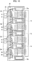
- Fig. 10 illustrates a mounting configuration of the power conversion device according to the sixth embodiment.
- a detection circuit 15a including a pickup coil whose number of turns is half that of each of the detection circuits 12 to 14 is provided on the opposite side of the detection circuit 12 with the first semiconductor switch Q1 in between.
- a detection circuit 15b including a pickup coil whose number of turns is half that of each of the detection circuits 12 to 14 is provided on the opposite side of the detection circuit 14 with the fourth semiconductor switch Q4 in between.
- the pickup coil of the detection circuit 15a and the pickup coil of the detection circuit 15b are connected in series.
- the gate terminal G1 is connected to one end of the pickup coil forming the detection circuit 15a, and the other end of this pickup coil is connected to the gate electrode of the first semiconductor switch Q1 via the detection circuit connection member 30 and the detection circuit 12.
- the gate terminal G4 is connected to one end of the pickup coil forming the detection circuit 15b via the detection circuit 14 and the detection circuit connection member 30, and the other end of this pickup coil is connected to the gate electrode of the fourth semiconductor switch Q4.
- the current of the first semiconductor switch Q1 and the current of the second semiconductor switch Q2, the current of the second semiconductor switch Q2 and the current of the third semiconductor switch Q3, and the current of the third semiconductor switch Q3 and the current of the fourth semiconductor switch Q4 can be balanced, respectively.
- operation can be obtained in which the current of the fourth semiconductor switch Q4 and the current of the first semiconductor switch Q1 are also balanced. Accordingly, even when an excessive current flows through the first semiconductor switch Q1 or the fourth semiconductor switch Q4 at both ends, the currents of all the semiconductor switches can be promptly balanced.
- a twisted wire is preferably used as the wire rod of the pickup coil extending over the first semiconductor switch Q1 to the fourth semiconductor switch Q4.
- the effect of balancing the currents flowing through the semiconductor switches can be obtained even in a power conversion device including the arbitrary number of semiconductor switches in parallel.
- the currents can also be constituted so as to be balanced between the semiconductor switches away from each other.
- the currents can be balanced between the semiconductor switches away from each other, such as the first semiconductor switch Q1 and the third semiconductor switch Q3 or the second semiconductor switch Q2 and the fourth semiconductor switch Q4.
- one gate drive circuit is provided and a drive signal is transmitted from this gate drive circuit to a plurality of semiconductor elements, but is not necessarily limited thereto, and the drive circuit may be provided for each semiconductor element or the gate drive circuit may be provided for each predetermined number of semiconductor elements.
Landscapes
- Engineering & Computer Science (AREA)
- Power Engineering (AREA)
- Power Conversion In General (AREA)
- Inverter Devices (AREA)
Applications Claiming Priority (1)
| Application Number | Priority Date | Filing Date | Title |
|---|---|---|---|
| PCT/JP2015/064743 WO2016189585A1 (fr) | 2015-05-22 | 2015-05-22 | Dispositif de conversion de puissance |
Publications (3)
| Publication Number | Publication Date |
|---|---|
| EP3300234A1 true EP3300234A1 (fr) | 2018-03-28 |
| EP3300234A4 EP3300234A4 (fr) | 2018-08-15 |
| EP3300234B1 EP3300234B1 (fr) | 2019-08-21 |
Family
ID=57392968
Family Applications (1)
| Application Number | Title | Priority Date | Filing Date |
|---|---|---|---|
| EP15893221.0A Active EP3300234B1 (fr) | 2015-05-22 | 2015-05-22 | Dispositif de conversion de puissance |
Country Status (10)
| Country | Link |
|---|---|
| US (1) | US10230294B2 (fr) |
| EP (1) | EP3300234B1 (fr) |
| JP (1) | JP6460231B2 (fr) |
| KR (1) | KR101992559B1 (fr) |
| CN (1) | CN107710575B (fr) |
| BR (1) | BR112017024998B1 (fr) |
| CA (1) | CA2986883C (fr) |
| MX (1) | MX360753B (fr) |
| RU (1) | RU2663827C1 (fr) |
| WO (1) | WO2016189585A1 (fr) |
Cited By (1)
| Publication number | Priority date | Publication date | Assignee | Title |
|---|---|---|---|---|
| EP4084312A4 (fr) * | 2020-02-04 | 2023-12-20 | OMRON Corporation | Circuit à semi-conducteurs |
Families Citing this family (6)
| Publication number | Priority date | Publication date | Assignee | Title |
|---|---|---|---|---|
| US9503079B1 (en) * | 2015-05-28 | 2016-11-22 | Toyota Motor Engineering & Manufacturing North America, Inc. | Method and apparatus for current/power balancing |
| WO2019016857A1 (fr) * | 2017-07-18 | 2019-01-24 | 株式会社日立ハイテクノロジーズ | Dispositif à faisceau de particules chargées |
| DE102017117566B4 (de) * | 2017-08-02 | 2022-07-21 | Technische Universität Dortmund | Vorrichtung und Verfahren zur homogenen Stromverteilung und/oder zur Reduzierung von Schaltverlusten von elektrisch steuerbaren Schaltelementen |
| JP2020167612A (ja) * | 2019-03-29 | 2020-10-08 | 住友電装株式会社 | 給電制御装置 |
| CN111181363B (zh) * | 2019-07-01 | 2020-10-16 | 苏州纳芯微电子股份有限公司 | 一种隔离电源电路及其控制方法 |
| WO2023157185A1 (fr) * | 2022-02-17 | 2023-08-24 | 三菱電機株式会社 | Circuit d'attaque de grille et dispositif de conversion de puissance |
Family Cites Families (17)
| Publication number | Priority date | Publication date | Assignee | Title |
|---|---|---|---|---|
| JPS4878432A (fr) | 1972-01-29 | 1973-10-22 | ||
| US3737756A (en) * | 1972-05-15 | 1973-06-05 | Bell Telephone Labor Inc | Converter circuit with balanced parallel switching paths |
| AT349104B (de) | 1974-12-27 | 1979-03-26 | Siemens Ag Oesterreich | Schaltungsanordnung mit parallelgeschalteten und durch eine gemeinsame steuerspannung gesteuerten transistoren |
| JPS5453954A (en) * | 1977-10-07 | 1979-04-27 | Fuji Electric Co Ltd | Parallel connection mthod of transistor |
| SU1083306A1 (ru) * | 1981-07-16 | 1984-03-30 | Предприятие П/Я Г-4514 | Устройство дл равномерного токораспределени при параллельном включении транзисторов,работающих в импульсном режиме с насыщением |
| SU1304007A1 (ru) * | 1985-11-05 | 1987-04-15 | Предприятие П/Я Г-4173 | Устройство дл автоматического выравнивани эмиттерных токов параллельно включенных транзисторов |
| JPH07177727A (ja) | 1993-12-22 | 1995-07-14 | Toshiba Corp | 電圧駆動型スイッチング素子のゲート駆動回路および電圧駆動型スイッチング素子のゲート駆動方法 |
| JPH0819246A (ja) * | 1994-07-04 | 1996-01-19 | Fuji Electric Co Ltd | 半導体スイッチ素子の並列接続回路 |
| JP3421544B2 (ja) | 1997-07-14 | 2003-06-30 | 株式会社東芝 | 半導体モジュール |
| JP2003244966A (ja) * | 2002-02-18 | 2003-08-29 | Mitsubishi Electric Corp | 駆動回路 |
| JP4082672B2 (ja) | 2003-03-06 | 2008-04-30 | 株式会社デンソー | 電気絶縁型スイッチング素子駆動回路 |
| JP2005005595A (ja) * | 2003-06-13 | 2005-01-06 | Murata Mfg Co Ltd | コイル部品 |
| JP2006049341A (ja) * | 2004-07-30 | 2006-02-16 | Renesas Technology Corp | 半導体装置およびその製造方法 |
| JP4586739B2 (ja) * | 2006-02-10 | 2010-11-24 | セイコーエプソン株式会社 | 半導体集積回路及び電子機器 |
| JP5954924B2 (ja) * | 2010-08-09 | 2016-07-20 | 富士電機株式会社 | 電力変換装置 |
| JP6255766B2 (ja) * | 2013-07-23 | 2018-01-10 | 日新電機株式会社 | ゲート駆動回路 |
| JP5850901B2 (ja) | 2013-11-08 | 2016-02-03 | 三菱電機株式会社 | 車載用電力変換装置 |
-
2015
- 2015-05-22 KR KR1020177034491A patent/KR101992559B1/ko active IP Right Grant
- 2015-05-22 CN CN201580080255.6A patent/CN107710575B/zh active Active
- 2015-05-22 BR BR112017024998-7A patent/BR112017024998B1/pt active IP Right Grant
- 2015-05-22 JP JP2017520063A patent/JP6460231B2/ja active Active
- 2015-05-22 WO PCT/JP2015/064743 patent/WO2016189585A1/fr active Application Filing
- 2015-05-22 RU RU2017144770A patent/RU2663827C1/ru active
- 2015-05-22 US US15/575,963 patent/US10230294B2/en active Active
- 2015-05-22 CA CA2986883A patent/CA2986883C/fr active Active
- 2015-05-22 MX MX2017014684A patent/MX360753B/es active IP Right Grant
- 2015-05-22 EP EP15893221.0A patent/EP3300234B1/fr active Active
Cited By (2)
| Publication number | Priority date | Publication date | Assignee | Title |
|---|---|---|---|---|
| EP4084312A4 (fr) * | 2020-02-04 | 2023-12-20 | OMRON Corporation | Circuit à semi-conducteurs |
| US11984885B2 (en) | 2020-02-04 | 2024-05-14 | Omron Corporation | Semiconductor circuit |
Also Published As
| Publication number | Publication date |
|---|---|
| EP3300234A4 (fr) | 2018-08-15 |
| MX2017014684A (es) | 2018-01-24 |
| JPWO2016189585A1 (ja) | 2018-04-05 |
| CA2986883A1 (fr) | 2016-12-01 |
| BR112017024998B1 (pt) | 2022-06-28 |
| CN107710575A (zh) | 2018-02-16 |
| US20180152093A1 (en) | 2018-05-31 |
| EP3300234B1 (fr) | 2019-08-21 |
| KR101992559B1 (ko) | 2019-06-24 |
| CN107710575B (zh) | 2019-01-01 |
| MX360753B (es) | 2018-11-15 |
| JP6460231B2 (ja) | 2019-01-30 |
| BR112017024998A2 (pt) | 2018-07-31 |
| US10230294B2 (en) | 2019-03-12 |
| RU2663827C1 (ru) | 2018-08-10 |
| CA2986883C (fr) | 2019-03-26 |
| WO2016189585A1 (fr) | 2016-12-01 |
| KR20180002736A (ko) | 2018-01-08 |
Similar Documents
| Publication | Publication Date | Title |
|---|---|---|
| US10230294B2 (en) | Power conversion device with gate drive circuit | |
| US10134718B2 (en) | Power semiconductor module | |
| JP6271765B1 (ja) | 半導体モジュール | |
| CN106208634B (zh) | 用于电流/功率平衡的方法和装置 | |
| US20180145513A1 (en) | Semiconductor device | |
| US9270166B2 (en) | Power factor improvement circuit | |
| JPWO2019038957A1 (ja) | 制御回路および電力変換装置 | |
| US10574223B1 (en) | Paralleled power semiconductors with chokes in gate path | |
| JP6319509B2 (ja) | 半導体装置 | |
| JP2016046842A (ja) | 電力変換装置およびそれを用いたエレベータ | |
| KR102117719B1 (ko) | 전력 반도체 회로 | |
| JP6261476B2 (ja) | 電力変換装置および電力変換装置の出力電圧検出方法 | |
| KR102055461B1 (ko) | 전력 반도체 회로 | |
| JP2014230138A (ja) | 半導体モジュールおよびスイッチング素子の駆動装置 | |
| JP5546892B2 (ja) | 昇圧回路 | |
| US10389255B2 (en) | Insulated synchronous rectification DC/DC converter | |
| US20160248337A1 (en) | Power Conversion Apparatus | |
| KR101998434B1 (ko) | 전류 측정 장치 및 전류 측정 장치의 작동 방법 | |
| US10700681B1 (en) | Paralleled power module with additional emitter/source path | |
| JP2004187360A (ja) | 電圧駆動型スイッチング素子のゲ−ト駆動回路および半導体モジュ−ル | |
| JP6838297B2 (ja) | 電力変換装置 | |
| US20130293002A1 (en) | Device comprising an electronic component with high switching speed | |
| CN107534015B (zh) | 保护电路及保护电路系统 | |
| JP2013017360A (ja) | 半導体装置、dc−dcコンバータ及び受像器 | |
| JP6503977B2 (ja) | 電力変換回路の制御方法および電力変換モジュール |
Legal Events
| Date | Code | Title | Description |
|---|---|---|---|
| STAA | Information on the status of an ep patent application or granted ep patent |
Free format text: STATUS: THE INTERNATIONAL PUBLICATION HAS BEEN MADE |
|
| PUAI | Public reference made under article 153(3) epc to a published international application that has entered the european phase |
Free format text: ORIGINAL CODE: 0009012 |
|
| STAA | Information on the status of an ep patent application or granted ep patent |
Free format text: STATUS: REQUEST FOR EXAMINATION WAS MADE |
|
| 17P | Request for examination filed |
Effective date: 20171205 |
|
| AK | Designated contracting states |
Kind code of ref document: A1 Designated state(s): AL AT BE BG CH CY CZ DE DK EE ES FI FR GB GR HR HU IE IS IT LI LT LU LV MC MK MT NL NO PL PT RO RS SE SI SK SM TR |
|
| AX | Request for extension of the european patent |
Extension state: BA ME |
|
| A4 | Supplementary search report drawn up and despatched |
Effective date: 20180717 |
|
| RIC1 | Information provided on ipc code assigned before grant |
Ipc: H02M 1/088 20060101AFI20180711BHEP Ipc: H02M 7/537 20060101ALI20180711BHEP Ipc: H02M 1/08 20060101ALI20180711BHEP Ipc: H03K 17/14 20060101ALN20180711BHEP Ipc: H02M 7/217 20060101ALI20180711BHEP |
|
| DAV | Request for validation of the european patent (deleted) | ||
| DAX | Request for extension of the european patent (deleted) | ||
| REG | Reference to a national code |
Ref country code: DE Ref legal event code: R079 Ref document number: 602015036513 Country of ref document: DE Free format text: PREVIOUS MAIN CLASS: H02M0001080000 Ipc: H02M0001088000 |
|
| GRAP | Despatch of communication of intention to grant a patent |
Free format text: ORIGINAL CODE: EPIDOSNIGR1 |
|
| STAA | Information on the status of an ep patent application or granted ep patent |
Free format text: STATUS: GRANT OF PATENT IS INTENDED |
|
| RIC1 | Information provided on ipc code assigned before grant |
Ipc: H02M 7/217 20060101ALI20190410BHEP Ipc: H02M 1/08 20060101ALI20190410BHEP Ipc: H03K 17/14 20060101ALN20190410BHEP Ipc: H02M 1/088 20060101AFI20190410BHEP Ipc: H02M 7/537 20060101ALI20190410BHEP |
|
| INTG | Intention to grant announced |
Effective date: 20190515 |
|
| GRAS | Grant fee paid |
Free format text: ORIGINAL CODE: EPIDOSNIGR3 |
|
| GRAA | (expected) grant |
Free format text: ORIGINAL CODE: 0009210 |
|
| STAA | Information on the status of an ep patent application or granted ep patent |
Free format text: STATUS: THE PATENT HAS BEEN GRANTED |
|
| AK | Designated contracting states |
Kind code of ref document: B1 Designated state(s): AL AT BE BG CH CY CZ DE DK EE ES FI FR GB GR HR HU IE IS IT LI LT LU LV MC MK MT NL NO PL PT RO RS SE SI SK SM TR |
|
| REG | Reference to a national code |
Ref country code: GB Ref legal event code: FG4D |
|
| REG | Reference to a national code |
Ref country code: CH Ref legal event code: EP |
|
| REG | Reference to a national code |
Ref country code: DE Ref legal event code: R096 Ref document number: 602015036513 Country of ref document: DE |
|
| REG | Reference to a national code |
Ref country code: AT Ref legal event code: REF Ref document number: 1170862 Country of ref document: AT Kind code of ref document: T Effective date: 20190915 |
|
| REG | Reference to a national code |
Ref country code: IE Ref legal event code: FG4D |
|
| REG | Reference to a national code |
Ref country code: LT Ref legal event code: MG4D |
|
| REG | Reference to a national code |
Ref country code: NL Ref legal event code: MP Effective date: 20190821 |
|
| PG25 | Lapsed in a contracting state [announced via postgrant information from national office to epo] |
Ref country code: FI Free format text: LAPSE BECAUSE OF FAILURE TO SUBMIT A TRANSLATION OF THE DESCRIPTION OR TO PAY THE FEE WITHIN THE PRESCRIBED TIME-LIMIT Effective date: 20190821 Ref country code: LT Free format text: LAPSE BECAUSE OF FAILURE TO SUBMIT A TRANSLATION OF THE DESCRIPTION OR TO PAY THE FEE WITHIN THE PRESCRIBED TIME-LIMIT Effective date: 20190821 Ref country code: NL Free format text: LAPSE BECAUSE OF FAILURE TO SUBMIT A TRANSLATION OF THE DESCRIPTION OR TO PAY THE FEE WITHIN THE PRESCRIBED TIME-LIMIT Effective date: 20190821 Ref country code: BG Free format text: LAPSE BECAUSE OF FAILURE TO SUBMIT A TRANSLATION OF THE DESCRIPTION OR TO PAY THE FEE WITHIN THE PRESCRIBED TIME-LIMIT Effective date: 20191121 Ref country code: NO Free format text: LAPSE BECAUSE OF FAILURE TO SUBMIT A TRANSLATION OF THE DESCRIPTION OR TO PAY THE FEE WITHIN THE PRESCRIBED TIME-LIMIT Effective date: 20191121 Ref country code: PT Free format text: LAPSE BECAUSE OF FAILURE TO SUBMIT A TRANSLATION OF THE DESCRIPTION OR TO PAY THE FEE WITHIN THE PRESCRIBED TIME-LIMIT Effective date: 20191223 Ref country code: HR Free format text: LAPSE BECAUSE OF FAILURE TO SUBMIT A TRANSLATION OF THE DESCRIPTION OR TO PAY THE FEE WITHIN THE PRESCRIBED TIME-LIMIT Effective date: 20190821 Ref country code: SE Free format text: LAPSE BECAUSE OF FAILURE TO SUBMIT A TRANSLATION OF THE DESCRIPTION OR TO PAY THE FEE WITHIN THE PRESCRIBED TIME-LIMIT Effective date: 20190821 |
|
| PG25 | Lapsed in a contracting state [announced via postgrant information from national office to epo] |
Ref country code: RS Free format text: LAPSE BECAUSE OF FAILURE TO SUBMIT A TRANSLATION OF THE DESCRIPTION OR TO PAY THE FEE WITHIN THE PRESCRIBED TIME-LIMIT Effective date: 20190821 Ref country code: IS Free format text: LAPSE BECAUSE OF FAILURE TO SUBMIT A TRANSLATION OF THE DESCRIPTION OR TO PAY THE FEE WITHIN THE PRESCRIBED TIME-LIMIT Effective date: 20191221 Ref country code: ES Free format text: LAPSE BECAUSE OF FAILURE TO SUBMIT A TRANSLATION OF THE DESCRIPTION OR TO PAY THE FEE WITHIN THE PRESCRIBED TIME-LIMIT Effective date: 20190821 Ref country code: GR Free format text: LAPSE BECAUSE OF FAILURE TO SUBMIT A TRANSLATION OF THE DESCRIPTION OR TO PAY THE FEE WITHIN THE PRESCRIBED TIME-LIMIT Effective date: 20191122 Ref country code: LV Free format text: LAPSE BECAUSE OF FAILURE TO SUBMIT A TRANSLATION OF THE DESCRIPTION OR TO PAY THE FEE WITHIN THE PRESCRIBED TIME-LIMIT Effective date: 20190821 Ref country code: AL Free format text: LAPSE BECAUSE OF FAILURE TO SUBMIT A TRANSLATION OF THE DESCRIPTION OR TO PAY THE FEE WITHIN THE PRESCRIBED TIME-LIMIT Effective date: 20190821 |
|
| REG | Reference to a national code |
Ref country code: AT Ref legal event code: MK05 Ref document number: 1170862 Country of ref document: AT Kind code of ref document: T Effective date: 20190821 |
|
| PG25 | Lapsed in a contracting state [announced via postgrant information from national office to epo] |
Ref country code: TR Free format text: LAPSE BECAUSE OF FAILURE TO SUBMIT A TRANSLATION OF THE DESCRIPTION OR TO PAY THE FEE WITHIN THE PRESCRIBED TIME-LIMIT Effective date: 20190821 |
|
| PG25 | Lapsed in a contracting state [announced via postgrant information from national office to epo] |
Ref country code: PL Free format text: LAPSE BECAUSE OF FAILURE TO SUBMIT A TRANSLATION OF THE DESCRIPTION OR TO PAY THE FEE WITHIN THE PRESCRIBED TIME-LIMIT Effective date: 20190821 Ref country code: EE Free format text: LAPSE BECAUSE OF FAILURE TO SUBMIT A TRANSLATION OF THE DESCRIPTION OR TO PAY THE FEE WITHIN THE PRESCRIBED TIME-LIMIT Effective date: 20190821 Ref country code: IT Free format text: LAPSE BECAUSE OF FAILURE TO SUBMIT A TRANSLATION OF THE DESCRIPTION OR TO PAY THE FEE WITHIN THE PRESCRIBED TIME-LIMIT Effective date: 20190821 Ref country code: AT Free format text: LAPSE BECAUSE OF FAILURE TO SUBMIT A TRANSLATION OF THE DESCRIPTION OR TO PAY THE FEE WITHIN THE PRESCRIBED TIME-LIMIT Effective date: 20190821 Ref country code: DK Free format text: LAPSE BECAUSE OF FAILURE TO SUBMIT A TRANSLATION OF THE DESCRIPTION OR TO PAY THE FEE WITHIN THE PRESCRIBED TIME-LIMIT Effective date: 20190821 Ref country code: RO Free format text: LAPSE BECAUSE OF FAILURE TO SUBMIT A TRANSLATION OF THE DESCRIPTION OR TO PAY THE FEE WITHIN THE PRESCRIBED TIME-LIMIT Effective date: 20190821 |
|
| PG25 | Lapsed in a contracting state [announced via postgrant information from national office to epo] |
Ref country code: SK Free format text: LAPSE BECAUSE OF FAILURE TO SUBMIT A TRANSLATION OF THE DESCRIPTION OR TO PAY THE FEE WITHIN THE PRESCRIBED TIME-LIMIT Effective date: 20190821 Ref country code: CZ Free format text: LAPSE BECAUSE OF FAILURE TO SUBMIT A TRANSLATION OF THE DESCRIPTION OR TO PAY THE FEE WITHIN THE PRESCRIBED TIME-LIMIT Effective date: 20190821 Ref country code: IS Free format text: LAPSE BECAUSE OF FAILURE TO SUBMIT A TRANSLATION OF THE DESCRIPTION OR TO PAY THE FEE WITHIN THE PRESCRIBED TIME-LIMIT Effective date: 20200224 Ref country code: SM Free format text: LAPSE BECAUSE OF FAILURE TO SUBMIT A TRANSLATION OF THE DESCRIPTION OR TO PAY THE FEE WITHIN THE PRESCRIBED TIME-LIMIT Effective date: 20190821 |
|
| REG | Reference to a national code |
Ref country code: DE Ref legal event code: R097 Ref document number: 602015036513 Country of ref document: DE |
|
| PLBE | No opposition filed within time limit |
Free format text: ORIGINAL CODE: 0009261 |
|
| STAA | Information on the status of an ep patent application or granted ep patent |
Free format text: STATUS: NO OPPOSITION FILED WITHIN TIME LIMIT |
|
| PG2D | Information on lapse in contracting state deleted |
Ref country code: IS |
|
| 26N | No opposition filed |
Effective date: 20200603 |
|
| PG25 | Lapsed in a contracting state [announced via postgrant information from national office to epo] |
Ref country code: SI Free format text: LAPSE BECAUSE OF FAILURE TO SUBMIT A TRANSLATION OF THE DESCRIPTION OR TO PAY THE FEE WITHIN THE PRESCRIBED TIME-LIMIT Effective date: 20190821 |
|
| PG25 | Lapsed in a contracting state [announced via postgrant information from national office to epo] |
Ref country code: LI Free format text: LAPSE BECAUSE OF NON-PAYMENT OF DUE FEES Effective date: 20200531 Ref country code: CH Free format text: LAPSE BECAUSE OF NON-PAYMENT OF DUE FEES Effective date: 20200531 Ref country code: MC Free format text: LAPSE BECAUSE OF FAILURE TO SUBMIT A TRANSLATION OF THE DESCRIPTION OR TO PAY THE FEE WITHIN THE PRESCRIBED TIME-LIMIT Effective date: 20190821 |
|
| REG | Reference to a national code |
Ref country code: BE Ref legal event code: MM Effective date: 20200531 |
|
| PG25 | Lapsed in a contracting state [announced via postgrant information from national office to epo] |
Ref country code: LU Free format text: LAPSE BECAUSE OF NON-PAYMENT OF DUE FEES Effective date: 20200522 |
|
| PG25 | Lapsed in a contracting state [announced via postgrant information from national office to epo] |
Ref country code: IE Free format text: LAPSE BECAUSE OF NON-PAYMENT OF DUE FEES Effective date: 20200522 |
|
| PG25 | Lapsed in a contracting state [announced via postgrant information from national office to epo] |
Ref country code: BE Free format text: LAPSE BECAUSE OF NON-PAYMENT OF DUE FEES Effective date: 20200531 |
|
| PG25 | Lapsed in a contracting state [announced via postgrant information from national office to epo] |
Ref country code: MT Free format text: LAPSE BECAUSE OF FAILURE TO SUBMIT A TRANSLATION OF THE DESCRIPTION OR TO PAY THE FEE WITHIN THE PRESCRIBED TIME-LIMIT Effective date: 20190821 Ref country code: CY Free format text: LAPSE BECAUSE OF FAILURE TO SUBMIT A TRANSLATION OF THE DESCRIPTION OR TO PAY THE FEE WITHIN THE PRESCRIBED TIME-LIMIT Effective date: 20190821 |
|
| PG25 | Lapsed in a contracting state [announced via postgrant information from national office to epo] |
Ref country code: MK Free format text: LAPSE BECAUSE OF FAILURE TO SUBMIT A TRANSLATION OF THE DESCRIPTION OR TO PAY THE FEE WITHIN THE PRESCRIBED TIME-LIMIT Effective date: 20190821 |
|
| PGFP | Annual fee paid to national office [announced via postgrant information from national office to epo] |
Ref country code: GB Payment date: 20240419 Year of fee payment: 10 |
|
| PGFP | Annual fee paid to national office [announced via postgrant information from national office to epo] |
Ref country code: DE Payment date: 20240418 Year of fee payment: 10 |
|
| PGFP | Annual fee paid to national office [announced via postgrant information from national office to epo] |
Ref country code: FR Payment date: 20240418 Year of fee payment: 10 |