EP3299271A1 - Installation structure for wheel axle assembly and wheel fork, frame and vehicle - Google Patents
Installation structure for wheel axle assembly and wheel fork, frame and vehicle Download PDFInfo
- Publication number
- EP3299271A1 EP3299271A1 EP17188828.2A EP17188828A EP3299271A1 EP 3299271 A1 EP3299271 A1 EP 3299271A1 EP 17188828 A EP17188828 A EP 17188828A EP 3299271 A1 EP3299271 A1 EP 3299271A1
- Authority
- EP
- European Patent Office
- Prior art keywords
- wheel
- wheel axle
- bearing
- installation structure
- structure according
- Prior art date
- Legal status (The legal status is an assumption and is not a legal conclusion. Google has not performed a legal analysis and makes no representation as to the accuracy of the status listed.)
- Withdrawn
Links
Images


Classifications
-
- B—PERFORMING OPERATIONS; TRANSPORTING
- B60—VEHICLES IN GENERAL
- B60B—VEHICLE WHEELS; CASTORS; AXLES FOR WHEELS OR CASTORS; INCREASING WHEEL ADHESION
- B60B35/00—Axle units; Parts thereof ; Arrangements for lubrication of axles
- B60B35/004—Mounting arrangements for axles
-
- B—PERFORMING OPERATIONS; TRANSPORTING
- B62—LAND VEHICLES FOR TRAVELLING OTHERWISE THAN ON RAILS
- B62K—CYCLES; CYCLE FRAMES; CYCLE STEERING DEVICES; RIDER-OPERATED TERMINAL CONTROLS SPECIALLY ADAPTED FOR CYCLES; CYCLE AXLE SUSPENSIONS; CYCLE SIDE-CARS, FORECARS, OR THE LIKE
- B62K25/00—Axle suspensions
- B62K25/005—Axle suspensions characterised by the axle being supported at one end only
-
- B—PERFORMING OPERATIONS; TRANSPORTING
- B60—VEHICLES IN GENERAL
- B60B—VEHICLE WHEELS; CASTORS; AXLES FOR WHEELS OR CASTORS; INCREASING WHEEL ADHESION
- B60B27/00—Hubs
- B60B27/02—Hubs adapted to be rotatably arranged on axle
- B60B27/023—Hubs adapted to be rotatably arranged on axle specially adapted for bicycles
-
- B—PERFORMING OPERATIONS; TRANSPORTING
- B62—LAND VEHICLES FOR TRAVELLING OTHERWISE THAN ON RAILS
- B62K—CYCLES; CYCLE FRAMES; CYCLE STEERING DEVICES; RIDER-OPERATED TERMINAL CONTROLS SPECIALLY ADAPTED FOR CYCLES; CYCLE AXLE SUSPENSIONS; CYCLE SIDE-CARS, FORECARS, OR THE LIKE
- B62K19/00—Cycle frames
- B62K19/18—Joints between frame members
-
- B—PERFORMING OPERATIONS; TRANSPORTING
- B62—LAND VEHICLES FOR TRAVELLING OTHERWISE THAN ON RAILS
- B62K—CYCLES; CYCLE FRAMES; CYCLE STEERING DEVICES; RIDER-OPERATED TERMINAL CONTROLS SPECIALLY ADAPTED FOR CYCLES; CYCLE AXLE SUSPENSIONS; CYCLE SIDE-CARS, FORECARS, OR THE LIKE
- B62K19/00—Cycle frames
- B62K19/30—Frame parts shaped to receive other cycle parts or accessories
-
- B—PERFORMING OPERATIONS; TRANSPORTING
- B62—LAND VEHICLES FOR TRAVELLING OTHERWISE THAN ON RAILS
- B62K—CYCLES; CYCLE FRAMES; CYCLE STEERING DEVICES; RIDER-OPERATED TERMINAL CONTROLS SPECIALLY ADAPTED FOR CYCLES; CYCLE AXLE SUSPENSIONS; CYCLE SIDE-CARS, FORECARS, OR THE LIKE
- B62K21/00—Steering devices
- B62K21/02—Front wheel forks or equivalent, e.g. single tine
-
- B—PERFORMING OPERATIONS; TRANSPORTING
- B62—LAND VEHICLES FOR TRAVELLING OTHERWISE THAN ON RAILS
- B62K—CYCLES; CYCLE FRAMES; CYCLE STEERING DEVICES; RIDER-OPERATED TERMINAL CONTROLS SPECIALLY ADAPTED FOR CYCLES; CYCLE AXLE SUSPENSIONS; CYCLE SIDE-CARS, FORECARS, OR THE LIKE
- B62K25/00—Axle suspensions
- B62K25/02—Axle suspensions for mounting axles rigidly on cycle frame or fork, e.g. adjustably
-
- B—PERFORMING OPERATIONS; TRANSPORTING
- B62—LAND VEHICLES FOR TRAVELLING OTHERWISE THAN ON RAILS
- B62K—CYCLES; CYCLE FRAMES; CYCLE STEERING DEVICES; RIDER-OPERATED TERMINAL CONTROLS SPECIALLY ADAPTED FOR CYCLES; CYCLE AXLE SUSPENSIONS; CYCLE SIDE-CARS, FORECARS, OR THE LIKE
- B62K3/00—Bicycles
- B62K3/02—Frames
- B62K3/10—Frames of single-beam type, i.e. connecting steering head to rear axle
-
- B—PERFORMING OPERATIONS; TRANSPORTING
- B62—LAND VEHICLES FOR TRAVELLING OTHERWISE THAN ON RAILS
- B62L—BRAKES SPECIALLY ADAPTED FOR CYCLES
- B62L1/00—Brakes; Arrangements thereof
- B62L1/005—Brakes; Arrangements thereof constructional features of brake elements, e.g. fastening of brake blocks in their holders
Definitions
- the present invention relates to an installation structure for a wheel axle assembly and a wheel fork, and also relates to a frame applying the above installation structure, and further relates to a vehicle applying the above frame, such as a two-wheeler, a three-wheeler and so on.
- One object of this invention is to provide an installation structure for a wheel axle assembly and a wheel fork, which has a simple, firm and compact structure, and is easy to process and assemble, and has a well durability.
- an installation structure for a wheel axle assembly and a wheel fork comprising a wheel axle assembly and a wheel fork, wherein the wheel axle assembly includes a wheel axle; a first bearing, a bush and a second wheel axle sleeved on the wheel axle successively; and a hub arranged on the outer rings of the first bearing and the second bearing, wherein the bush is used for spacing apart the first bearing and the second bearing axially a predetermined distance, and the hub is of a sleeve shape and an end thereof arranged on the first bearing expands the outer diameter to form a flange portion for fixing and installing a wheel; and the wheel fork includes a wheel fork body and a frame connection portion formed on an end of the wheel fork body and forming an L shape with the wheel fork body for connecting to a frame, and the wheel axle is fixed on the other end of the wheel fork body in a direction perpendicular to the rim center plane of the wheel.
- the wheel axle and the ends of the wheel fork body are integrally formed.
- the end of the wheel fork body form a wheel axle installation portion in an extending manner in the direction thereof; wherein along a direction perpendicular to the rim center plane of the wheel, the wheel axle installation portion is provided with a wheel axle installation hole for fixedly connecting the wheel axle.
- the section of at least a part of the wheel axle installation hole is non-round; and at least a part of the wheel axle being fixedly assembled in the wheel axle installation holes is processed of a non-round shape corresponding thereto.
- the wheel axle installation hole is stepped hole, and a stepped portion of the stepped hole is used for being clamped and fixed with a cap portion provided in correspondence of an end of the wheel axle.
- the wheel axle installation hole is sized to be interference-fitted with the wheel axle.
- the wheel fork body and the frame connection portion are integrally formed.
- At least a plurality of reinforcement ribs is formed on the wheel fork body.
- a space for installing a brake operating in a central braking manner is provided between the second bearing and the wheel fork in the axial direction of the wheel axle.
- a brake operating in a roller braking manner is installed in the space, and a periphery of an end of the hub which is arranged on the second bearing is processed of a gear shape to act as an inner ring fluted disc of the brake operating in a roller braking manner.
- the periphery of the end of the hub which is processed of a gear shape is an independently manufactured embedded member which is embedded and fixed on the hub body of the hub.
- the installation structure further comprises a positioning member installed in a manner of clamping the first bearing with the bush in the axial direction and not affecting the rotation of the outer ring of the first bearing.
- a frame is also provided, comprising the installation structure mentioned above.
- a vehicle applying the frame mentioned above is also provided.
- the vehicle is a two-wheeler or a three-wheeler.
- the installation structure provided in the present invention has a simple, firm and compact structure and is easy to process and assemble with good duration.
- the state of the bicycle shown in Fig. 1 is taken for reference, that is, the state where the bicycle stands on the floor vertically.
- the direction of the bicycle head is defined as "front”
- the direction of the bicycle tail is defined as “rear”
- the left of the bicycle when viewing the front of the bicycle head is defined as “left”
- the right of the bicycle when viewing the front of the bicycle head is defined as “right”
- the vertical upward direction is defined as “up”
- the vertical downward direction is defined as "down”
- the plane of the rim center of the wheel is defined as the rim central plane, to describe the directions and positions of various constituent structures of the bicycle.
- Fig. 1 is a diagram schematically representing the entire construction of a bicycle according to an embodiment of the present invention.
- the bicycle according to an embodiment of the present invention mainly includes a frame 100, a wheel axle assembly 200a, a middle axle assembly 300, a rear axle assembly 400, a wheel 500,a handle, a seat, a crank and pedals , wherein the handle, the seat, the crank and the pedals are not shown.
- the frame 100 includes a wheel fork 110a, a head tube 120, a frame lower tube 130, an integrated underframe 140 and a seat tube 150.
- the wheel fork 110a may be rotatably connected to an end of the head tube 120 around the axial direction of the head tube 120.
- the other end of the head tube 120 is used for installing the handle (not shown).
- the head tube 120 is relatively fixedly connected to an end of the frame lower tube 130 in the middle.
- the other end of the frame lower tube 130 is relatively fixedly connected to a frame lower tube connection portion of the integrated underframe 140.
- An end of the seat tube 150 is relatively fixedly connected to a seat tube connection portion of the integrated underframe 140.
- the other end of the seat tube 150 is used for installing the seat (not shown).
- the integrated underframe 140 is an integrated member with functions of bottom bracket, rear lower fork and rear axle installation portion.
- the rear lower fork portion thereof merely exists at a single side of the rear wheel, that is, a single-fork structure.
- the wheel fork 110a is also a single-fork structure, that is, merely exists at a single side of the wheel.
- Fig. 2 is a schematic diagram for describing the construction of the front fork in the background art.
- Fig. 2(A) is a front view of the front fork.
- Fig. 2(B) is a left view of the front fork.
- Fig. 2(C) is a perspective view of the front fork.
- a wheel axle installation portion 113 which extends out in the direction of the wheel axle some distance is provided at one end of the front fork body 111 at the wheel axle side for assembling the wheel axle assembly.
- the structure of the wheel axle installation portion 113 can ensure an axial space for assembling the wheel axle assembly 200 in the wheel axle installation portion and ensure that there is a sufficient separation distance between two bearings 203 and 205 which support the wheel axle 201 at two points in the axial direction.
- Fig. 3 is a section view of a wheel axle assembly in the background art.
- the wheel axle assembly 200 includes a wheel axle 201, and a jump ring 202, a bearing 203, a shaft shoulder 204, a bearing 205, a spacer bush 206, a flange disc 700 and a positioning nut 208 arranged along the axial direction of the wheel axle 201 from one end to the other end at the side where the wheel fork 110 is located.
- a keyway-flat key construction 209 is also provided therebetween.
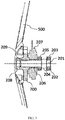
- Figs. 4(A) and 4(B) are schematic diagrams for describing the construction of the wheel fork 110a according to an embodiment of the present invention.
- the wheel fork 110a in the present invention is merely provided at one side of the wheel, that is, the so-called single wheel fork, entirely in an L shape. That is, it is integrally formed by the wheel fork body 111a extending in the direction parallel to the rim central plane, a head tube connection portion 112a at one end of the wheel fork body 111a extending in the direction perpendicular to the rim central plane and a wheel axle installation portion 113a formed at the other end of the wheel fork body 111a in the direction thereof.
- the wheel axle installation portion in the present invention does not extend out a certain distance substantially in the wheel axle direction, and the thickness of the wheel axle installation portion is approximately equal to the entire thickness of the wheel fork body 111a. The reason for providing the wheel axle installation portion 113a so will be described hereinafter.
- connection hole for connecting the head tube 120 is provided at the head tube connection portion 112a.
- the head tube 120 is inserted in the connection hole and fixed relative to the wheel fork 110a by means of welding or riveting.
- this connection hole may not be provided.
- the head tube connection portion 112a of the wheel fork 110a is fixed on the head tube 120 directly by means of welding or riveting.
- a wheel axle installation hole 115a is opened at the wheel axle installation portion 113a in the direction perpendicular to the rim central plane for assembling a wheel axle 201a described below.
- reinforcement ribs may be provided at least at a part of the inner side of the wheel fork body 111a of the wheel fork 110a.
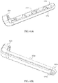
- Figs. 5(A) and 5(B) are graphs schematically representing the assembly relationship between the wheel fork 110a and the wheel axle 201a according to an embodiment of the present invention.
- the wheel axle 201a is of a cylinder structure entirely and is provided at one end with a cap portion 207a for being clamped and fixed in a stepped hole of a wheel axle installation hole described below.
- a wheel axle installation hole 115a for the wheel axle 201a to pass through and fix is opened at the wheel axle installation portion 113a of the wheel fork 110a in the direction perpendicular to the rim central plane.
- the wheel axle installation hole 115a is a stepped hole.
- the stepped portion of the stepped hole (also referred to as cap clamping and fixation portion hereafter) is clamped and fixed with the cap portion 207a provided at one end of the wheel axle so as to position the wheel axle in the axial direction.
- the wheel axle 201a and the wheel fork 110a are relatively fixed without relative rotation.
- the structure for preventing relative rotation may employ any known methods for relatively fixing two members.
- the cap portion 207a of the wheel axle 201a may be of a non-round shape, such as a long circular shape, as shown in Fig. 5(A) .
- the cap clamping and fixing portion of the wheel axle installation hole may be of a shape mating with the cap portion, thereby preventing relative rotation therebetween.
- the sections of the wheel axle installation hole and any part of the wheel axle which is inserted in the wheel axle installation hole may be of a non-round shape.
- the wheel fork and the wheel axle may be relatively fixed through a keyway-flat key structure or they may be integrally formed and so on.
- Fig. 6 is a section view of a wheel axle assembly 200a according to an embodiment of the present invention.
- the wheel axle assembly includes a wheel axle 201a, and a bearing 203a, a bush 206a and a bearing 205a successively sleeved on the wheel axle from a wheel installation end of the wheel axle (an opposite end provided with a cap portion), and a hub 204a arranged at the outer rings of the two bearings 203a and 205a.
- the assembling of the wheel axle assembly 200a will be described.
- a brake (not shown), the bearing 205a, the bush 206a, the hub 204a and the bearing 203a are successively sleeved from the wheel installation end of the wheel axle 201a.
- the brake preferably adopts roller brake.
- the bearing 205a is abutted against the brake without affecting the rotation of the out ring, and the other side is abutted against by the bush 206a, thus being positioned in the axial direction of the wheel axle 201a.
- the hub 204a is sleeved on.
- the hub 204a is of a sleeve shape.
- One end of the hub close to the wheel fork is sleeved on the outer ring of the bearing 205a and one end thereof close to the wheel side is sleeved on the outer ring of the bearing 203a, thus being arranged between the outer rings of the bearings 205a and 203a and being capable of rotating with the outer rings of the bearings.
- the outer diameter of the wheel installation end of the hub 204a expands to form a flange portion which is provided circumferentially with screw holes for installing the wheel (not shown).
- an embedded member 202a casted in the hub body in advance is adopted.
- the hub is sleeved on the bearing 205a with this embedded member 202a.
- the periphery of the portion of the embedded member 202a exposed out of the hub body is formed as gear which is used as the inner ring fluted disc of the roller brake.
- This embedded member of a gear shape may be manufactured independently and embedded in the hub body by means of casting, which can save manufacture costs. Of course, this embedded member may be not manufactured additionally. Instead, the end of the hub close to the wheel fork side may be directly processed into a corresponding shape.
- the gear shaped portion of the hub 204a is inserted in the center of the roller brake and also functions as a center gear thereof, such that the assembling of various components on the wheel axle may be more compact, saving the assembling space of the wheel axle.
- a roller brake method is employed in this embodiment.
- Other center braking methods such as disc brake, drum brake, contact type and so on may also be employed.
- the provision of the above wheel axle assembly enables two bearings to be supported in the hub which operates as an independent component, and thus ensuring the spacing between the two bearings, such that the support force of the wheel axle is more balanced and stable and the number of components may be reduced.
- An interference fit method may be employed between the wheel axle and the wheel axle installation hole of the wheel fork, such that no swing will be produced therebetween.
- a sliding mating method may be employed between the two bearings as well as the bush and the wheel axle.
- a sliding mating method may also be employed between the hub (embedded member) and the bearing, thus the assembling of the wheel axle assembly becomes easier.
- the construction of the wheel fork in the present invention is described by taking a front fork of a bicycle as an example.
- the wheel fork in the present invention is not only suitable for two-wheel bicycles but also suitable for electric bicycles, motorcycles, three-wheel bicycles, three-wheel motorcycles and so on. That is, as long as a wheel fork is a non-drive wheel, the wheel fork in the present invention may be applied.
- the wheel fork is described as a single wheel fork in this embodiment.
- a support arm for supporting the wheel may be provided at the other side of the wheel.
- Fig. 7 is graph representing the structure of a wheel hub of a wheel 500 according to an embodiment of the present invention, (A) is a front view of the wheel hub, and (B) is a section view of the wheel hub in (A) in the direction A-A'(diameter).
- the wheel hub of the wheel 500 comprises a rim 501 for installing a tire, a wheel disc (installation disc) 503 at the centre of the wheel hub for installing the rim on a wheel axle (wheel axle 201a mentioned before) and a spoke 502 connected between the rim 501 and the wheel disc 503 for supporting the rim 501.
- the spoke 502 may be fixedly connected between the rim 501 and the wheel disc 503 as a separate component by means of welding and may also be integrally formed with the rim 501 and the wheel disc 503.
- a plurality of bolt holes 504 is provided along the periphery portion of the wheel disc 503, and the positions thereof correspond to a plurality of installation holes of the flange portion of the hub 204a mentioned before respectively.
- the wheel 500 is installed at the wheel installation end of the wheel axle 201a by means of bolt fixing.
- the wheel hub according to an embodiment of the present invention is an eccentric wheel.
- the extension direction of the spoke 502 inclines at a certain angle ⁇ relative to the wheel axle direction, where ⁇ is smaller than 90 degrees. That is, the spoke does not extend along the direction perpendicular to the wheel axle.
- ⁇ is smaller than 90 degrees. That is, the spoke does not extend along the direction perpendicular to the wheel axle.
- the size of the offset d may be adjusted by designing the inclination angle ⁇ of the spoke 502, and at the same time, the length of the bush on the wheel axle 201a is designed, such that the rim central plane may be close to the center of the wheel axle as much as possible.
- the load of the wheel axle and the bearing may be reduced, the service life of the wheel axle and the bearing may be extended, or the requirements to the strength of the wheel axle and the bearing may be reduced.
- the offset d is set such that for example, the roller brake is at the rim central plane or nearby. At this moment, the braking performance of the brake is better.
Applications Claiming Priority (2)
| Application Number | Priority Date | Filing Date | Title |
|---|---|---|---|
| CN201610857565.0A CN107867363A (zh) | 2016-09-27 | 2016-09-27 | 两轮车、三轮车及其车轮用的轮轴组件、车轮安装方法 |
| CN201610857665.3A CN107867356A (zh) | 2016-09-27 | 2016-09-27 | 两轮车、三轮车及其车架、车轮用的轮叉 |
Publications (1)
| Publication Number | Publication Date |
|---|---|
| EP3299271A1 true EP3299271A1 (en) | 2018-03-28 |
Family
ID=59761797
Family Applications (1)
| Application Number | Title | Priority Date | Filing Date |
|---|---|---|---|
| EP17188828.2A Withdrawn EP3299271A1 (en) | 2016-09-27 | 2017-08-31 | Installation structure for wheel axle assembly and wheel fork, frame and vehicle |
Country Status (5)
| Country | Link |
|---|---|
| US (1) | US10583690B2 (zh) |
| EP (1) | EP3299271A1 (zh) |
| JP (1) | JP6880065B2 (zh) |
| KR (1) | KR102181678B1 (zh) |
| WO (1) | WO2018059055A1 (zh) |
Cited By (1)
| Publication number | Priority date | Publication date | Assignee | Title |
|---|---|---|---|---|
| WO2021152324A1 (en) * | 2020-01-29 | 2021-08-05 | Karbon Kinetics Limited | Bicycle with cantilevered single side mounted wheels |
Families Citing this family (3)
| Publication number | Priority date | Publication date | Assignee | Title |
|---|---|---|---|---|
| US10953951B2 (en) * | 2014-12-18 | 2021-03-23 | Raphael Schlanger | Cantilever axle assembly |
| CN110562374A (zh) * | 2019-09-20 | 2019-12-13 | 创呈工业设计(上海)有限公司 | 一种跨骑式电动车后轮单摇臂总成 |
| US20220081057A1 (en) * | 2020-09-17 | 2022-03-17 | Wilfried Dreyfuss | Modular Biking Device |
Citations (7)
| Publication number | Priority date | Publication date | Assignee | Title |
|---|---|---|---|---|
| DE8438112U1 (de) * | 1984-12-28 | 1985-03-28 | Dürkopp System Technik GmbH, 4800 Bielefeld | Fahrrad |
| JPH01145691U (zh) * | 1988-03-17 | 1989-10-06 | ||
| FR2653402A3 (fr) * | 1989-10-25 | 1991-04-26 | Makhalian David | Fourche de moto a demontage de roue axial. |
| DE4316254A1 (de) * | 1993-05-14 | 1994-11-17 | Damian Sowa | Schnellverschluß |
| FR2725128A1 (fr) * | 1994-09-30 | 1996-04-05 | Tis Sa | Moyeu a demontage rapide pour fauteuil roulant notamment pour handicapes physiques |
| US6474432B1 (en) * | 2001-07-05 | 2002-11-05 | Honda Giken Kogyo Kabushiki Kaisha | Adjustable front axle and brake carrier structure |
| CN105346668A (zh) * | 2015-09-29 | 2016-02-24 | 北京摩拜科技有限公司 | 无链自行车及其后轴组件 |
Family Cites Families (33)
| Publication number | Priority date | Publication date | Assignee | Title |
|---|---|---|---|---|
| US3124391A (en) * | 1964-03-10 | dishman | ||
| US2011402A (en) * | 1934-02-20 | 1935-08-13 | John W Gallo | Velocipede |
| US2197658A (en) * | 1938-12-05 | 1940-04-16 | Louis H Segel | Velocipede |
| US2809870A (en) * | 1953-08-31 | 1957-10-15 | Deere & Co | Wheel mounting |
| US4170369A (en) * | 1978-01-23 | 1979-10-09 | Lauren Strutman | Bicycle wheel suspension, driving and braking assembly |
| JPS5970277A (ja) * | 1982-10-14 | 1984-04-20 | 本田技研工業株式会社 | 自動二輪車の後輪支持装置 |
| US4733757A (en) * | 1984-05-26 | 1988-03-29 | Honda Giken Kogyo Kabushiki Kaisha | Brake device for vehicles |
| JP2524999B2 (ja) * | 1987-04-21 | 1996-08-14 | 本田技研工業株式会社 | 自動2輪車の後輪支持装置 |
| ATE108153T1 (de) * | 1989-04-19 | 1994-07-15 | Emco Maier Gmbh | Gestell für ein motorrad. |
| WO1991012166A1 (en) * | 1990-02-14 | 1991-08-22 | Parker James G | Rear swing arm suspension system for a motorcycle |
| JP2934077B2 (ja) * | 1990-10-20 | 1999-08-16 | 株式会社シマノ | 自転車用動作装置に対する操作力取出装置 |
| US5209319A (en) * | 1992-03-17 | 1993-05-11 | Buell Motor Co. | Motorcycle front suspension |
| ES2067389B1 (es) * | 1993-02-23 | 1998-03-01 | Navas Antonio Guerra | Buje para ruedas de bicicletas. |
| US5417305A (en) * | 1993-09-13 | 1995-05-23 | Parker; James G. | Front swing arm suspension system for a motorcycle |
| ES2156693B1 (es) * | 1998-12-30 | 2002-02-01 | Bertrand Juan Elizalde | Sistema para relacionar entre si las ruedas delantera y trasera en vehiculos de dos ruedas y vehiculo obtenido segun dicho sistema. |
| US6193323B1 (en) * | 1999-07-21 | 2001-02-27 | Hui-Liang Lin | Hidden type quick-release wheel hub assembly with reinforcing arrangement |
| JP4499320B2 (ja) * | 2001-09-07 | 2010-07-07 | 本田技研工業株式会社 | 車両用ホイール |
| BR8103051Y1 (pt) * | 2001-12-28 | 2010-12-14 | bicicleta infantil. | |
| JP3950870B2 (ja) * | 2004-05-14 | 2007-08-01 | 株式会社シマノ | 自転車用ブレーキ装置 |
| DE102006045625A1 (de) * | 2006-09-27 | 2008-04-03 | Ktm Sportmotorcycle Ag | Hinterradschwinge für ein Motorrad |
| US7494145B2 (en) * | 2006-10-27 | 2009-02-24 | Answer Products, Inc. | Axle with non-round tapered ends affixed into fork leg dropouts with openings that match the axle ends for a bicycle fork |
| CN201021065Y (zh) * | 2007-03-09 | 2008-02-13 | 谢刚贵 | 手推车花鼓筒 |
| TW200916339A (en) * | 2007-09-06 | 2009-04-16 | Aleksandr Sherman | Bicycle wheel |
| US7793960B2 (en) * | 2008-04-01 | 2010-09-14 | Aleksandr Sherman | Bicycle wheel mounting assembly |
| CN201573753U (zh) * | 2009-09-10 | 2010-09-08 | 熊耀榜 | 三轮车前车轮悬挂总成结构 |
| US8820853B1 (en) * | 2010-03-25 | 2014-09-02 | Eko Sport, Inc. | Wheel axle assembly |
| JP2013006528A (ja) * | 2011-06-24 | 2013-01-10 | Honda Motor Co Ltd | 電動自動二輪車 |
| CN202481202U (zh) * | 2012-03-06 | 2012-10-10 | 宇轮工业股份有限公司 | 单叉臂独轮车 |
| JP2017047764A (ja) * | 2015-09-01 | 2017-03-09 | ヤマハ発動機株式会社 | 鞍乗型車両 |
| CN105270528B (zh) * | 2015-09-29 | 2018-07-17 | 北京摩拜科技有限公司 | 无链自行车及其集成底架 |
| CN105270561B (zh) | 2015-09-29 | 2018-10-12 | 北京摩拜科技有限公司 | 无链自行车及其轮叉、车架 |
| CN206231544U (zh) * | 2016-09-27 | 2017-06-09 | 北京摩拜科技有限公司 | 两轮车、三轮车及其车轮用的轮轴组件 |
| CN206107440U (zh) * | 2016-09-27 | 2017-04-19 | 北京摩拜科技有限公司 | 两轮车、三轮车及其车架、车轮用的轮叉 |
-
2017
- 2017-07-05 KR KR1020197000577A patent/KR102181678B1/ko active IP Right Grant
- 2017-07-05 WO PCT/CN2017/091883 patent/WO2018059055A1/zh active Application Filing
- 2017-07-05 JP JP2018553954A patent/JP6880065B2/ja active Active
- 2017-08-31 EP EP17188828.2A patent/EP3299271A1/en not_active Withdrawn
- 2017-09-07 US US15/697,719 patent/US10583690B2/en not_active Expired - Fee Related
Patent Citations (7)
| Publication number | Priority date | Publication date | Assignee | Title |
|---|---|---|---|---|
| DE8438112U1 (de) * | 1984-12-28 | 1985-03-28 | Dürkopp System Technik GmbH, 4800 Bielefeld | Fahrrad |
| JPH01145691U (zh) * | 1988-03-17 | 1989-10-06 | ||
| FR2653402A3 (fr) * | 1989-10-25 | 1991-04-26 | Makhalian David | Fourche de moto a demontage de roue axial. |
| DE4316254A1 (de) * | 1993-05-14 | 1994-11-17 | Damian Sowa | Schnellverschluß |
| FR2725128A1 (fr) * | 1994-09-30 | 1996-04-05 | Tis Sa | Moyeu a demontage rapide pour fauteuil roulant notamment pour handicapes physiques |
| US6474432B1 (en) * | 2001-07-05 | 2002-11-05 | Honda Giken Kogyo Kabushiki Kaisha | Adjustable front axle and brake carrier structure |
| CN105346668A (zh) * | 2015-09-29 | 2016-02-24 | 北京摩拜科技有限公司 | 无链自行车及其后轴组件 |
Cited By (1)
| Publication number | Priority date | Publication date | Assignee | Title |
|---|---|---|---|---|
| WO2021152324A1 (en) * | 2020-01-29 | 2021-08-05 | Karbon Kinetics Limited | Bicycle with cantilevered single side mounted wheels |
Also Published As
| Publication number | Publication date |
|---|---|
| US10583690B2 (en) | 2020-03-10 |
| US20180086139A1 (en) | 2018-03-29 |
| KR102181678B1 (ko) | 2020-11-24 |
| US20180354301A9 (en) | 2018-12-13 |
| WO2018059055A1 (zh) | 2018-04-05 |
| JP6880065B2 (ja) | 2021-06-02 |
| JP2019518641A (ja) | 2019-07-04 |
| KR20190017903A (ko) | 2019-02-20 |
Similar Documents
| Publication | Publication Date | Title |
|---|---|---|
| US10583690B2 (en) | Installation structure for wheel axle assembly and wheel fork, frame and vehicle | |
| JP2002120503A (ja) | 自転車用ホイールハブ | |
| EP1975057A2 (en) | Bicycle shaft component | |
| EP2557030B1 (en) | Bicycle bottom bracket assembly | |
| US20090145262A1 (en) | Bottom bracket assembly for a bicycle and shaft for such an assembly | |
| CN206107440U (zh) | 两轮车、三轮车及其车架、车轮用的轮叉 | |
| CN205186403U (zh) | 两轮车及其车架、集成底架、底架主体 | |
| TW201700342A (zh) | 自行車曲柄總成 | |
| CN105270561A (zh) | 无链自行车及其轮叉、车架 | |
| EP2930032B1 (en) | Saddle riding type vehicle | |
| CN105346668B (zh) | 无链自行车及其后轴组件 | |
| US9388847B1 (en) | Bottom bracket for bicycles | |
| US10377437B2 (en) | Internal steering structure of a front wheel hub of a portable two-wheeled vehicle | |
| CN205186463U (zh) | 圆锥齿轮-传动杆传动方式的两轮车及其后轴组件 | |
| CN107867363A (zh) | 两轮车、三轮车及其车轮用的轮轴组件、车轮安装方法 | |
| US20090232436A1 (en) | Bicycle bearings | |
| CN206231544U (zh) | 两轮车、三轮车及其车轮用的轮轴组件 | |
| JP2006142947A (ja) | 自転車用クランク軸組立体 | |
| CN210364236U (zh) | 一种低自重高耐久的新型电动车中轴总成 | |
| TW201801990A (zh) | 多重自行車鏈輪總成 | |
| CN107867356A (zh) | 两轮车、三轮车及其车架、车轮用的轮叉 | |
| EP1975054B2 (en) | Bicycle bottom bracket hanger | |
| CN218876759U (zh) | 一种轻量化的组合式自行车花鼓结构 | |
| CN105346669B (zh) | 无链自行车及其轮组 | |
| JP2012148738A (ja) | 鞍乗型車両の駆動輪構造 |
Legal Events
| Date | Code | Title | Description |
|---|---|---|---|
| PUAI | Public reference made under article 153(3) epc to a published international application that has entered the european phase |
Free format text: ORIGINAL CODE: 0009012 |
|
| 17P | Request for examination filed |
Effective date: 20170831 |
|
| AK | Designated contracting states |
Kind code of ref document: A1 Designated state(s): AL AT BE BG CH CY CZ DE DK EE ES FI FR GB GR HR HU IE IS IT LI LT LU LV MC MK MT NL NO PL PT RO RS SE SI SK SM TR |
|
| AX | Request for extension of the european patent |
Extension state: BA ME |
|
| 17Q | First examination report despatched |
Effective date: 20180410 |
|
| STAA | Information on the status of an ep patent application or granted ep patent |
Free format text: STATUS: THE APPLICATION IS DEEMED TO BE WITHDRAWN |
|
| 18D | Application deemed to be withdrawn |
Effective date: 20200303 |