EP3299193B1 - An air suspension assembly - Google Patents
An air suspension assembly Download PDFInfo
- Publication number
- EP3299193B1 EP3299193B1 EP17001578.8A EP17001578A EP3299193B1 EP 3299193 B1 EP3299193 B1 EP 3299193B1 EP 17001578 A EP17001578 A EP 17001578A EP 3299193 B1 EP3299193 B1 EP 3299193B1
- Authority
- EP
- European Patent Office
- Prior art keywords
- chamber
- disposed
- center axis
- extending
- diaphragm
- Prior art date
- Legal status (The legal status is an assumption and is not a legal conclusion. Google has not performed a legal analysis and makes no representation as to the accuracy of the status listed.)
- Active
Links
Images


Classifications
-
- B—PERFORMING OPERATIONS; TRANSPORTING
- B60—VEHICLES IN GENERAL
- B60G—VEHICLE SUSPENSION ARRANGEMENTS
- B60G11/00—Resilient suspensions characterised by arrangement, location or kind of springs
- B60G11/26—Resilient suspensions characterised by arrangement, location or kind of springs having fluid springs only, e.g. hydropneumatic springs
- B60G11/27—Resilient suspensions characterised by arrangement, location or kind of springs having fluid springs only, e.g. hydropneumatic springs wherein the fluid is a gas
-
- B—PERFORMING OPERATIONS; TRANSPORTING
- B60—VEHICLES IN GENERAL
- B60G—VEHICLE SUSPENSION ARRANGEMENTS
- B60G17/00—Resilient suspensions having means for adjusting the spring or vibration-damper characteristics, for regulating the distance between a supporting surface and a sprung part of vehicle or for locking suspension during use to meet varying vehicular or surface conditions, e.g. due to speed or load
- B60G17/02—Spring characteristics, e.g. mechanical springs and mechanical adjusting means
- B60G17/04—Spring characteristics, e.g. mechanical springs and mechanical adjusting means fluid spring characteristics
- B60G17/052—Pneumatic spring characteristics
- B60G17/0521—Pneumatic spring characteristics the spring having a flexible wall
-
- F—MECHANICAL ENGINEERING; LIGHTING; HEATING; WEAPONS; BLASTING
- F16—ENGINEERING ELEMENTS AND UNITS; GENERAL MEASURES FOR PRODUCING AND MAINTAINING EFFECTIVE FUNCTIONING OF MACHINES OR INSTALLATIONS; THERMAL INSULATION IN GENERAL
- F16F—SPRINGS; SHOCK-ABSORBERS; MEANS FOR DAMPING VIBRATION
- F16F9/00—Springs, vibration-dampers, shock-absorbers, or similarly-constructed movement-dampers using a fluid or the equivalent as damping medium
- F16F9/02—Springs, vibration-dampers, shock-absorbers, or similarly-constructed movement-dampers using a fluid or the equivalent as damping medium using gas only or vacuum
- F16F9/04—Springs, vibration-dampers, shock-absorbers, or similarly-constructed movement-dampers using a fluid or the equivalent as damping medium using gas only or vacuum in a chamber with a flexible wall
- F16F9/05—Springs, vibration-dampers, shock-absorbers, or similarly-constructed movement-dampers using a fluid or the equivalent as damping medium using gas only or vacuum in a chamber with a flexible wall the flexible wall being of the rolling diaphragm type
- F16F9/057—Springs, vibration-dampers, shock-absorbers, or similarly-constructed movement-dampers using a fluid or the equivalent as damping medium using gas only or vacuum in a chamber with a flexible wall the flexible wall being of the rolling diaphragm type characterised by the piston
-
- B—PERFORMING OPERATIONS; TRANSPORTING
- B60—VEHICLES IN GENERAL
- B60G—VEHICLE SUSPENSION ARRANGEMENTS
- B60G11/00—Resilient suspensions characterised by arrangement, location or kind of springs
- B60G11/32—Resilient suspensions characterised by arrangement, location or kind of springs having springs of different kinds
- B60G11/48—Resilient suspensions characterised by arrangement, location or kind of springs having springs of different kinds not including leaf springs
- B60G11/56—Resilient suspensions characterised by arrangement, location or kind of springs having springs of different kinds not including leaf springs having helical, spiral or coil springs, and also fluid springs
- B60G11/58—Resilient suspensions characterised by arrangement, location or kind of springs having springs of different kinds not including leaf springs having helical, spiral or coil springs, and also fluid springs arranged coaxially
-
- B—PERFORMING OPERATIONS; TRANSPORTING
- B60—VEHICLES IN GENERAL
- B60G—VEHICLE SUSPENSION ARRANGEMENTS
- B60G17/00—Resilient suspensions having means for adjusting the spring or vibration-damper characteristics, for regulating the distance between a supporting surface and a sprung part of vehicle or for locking suspension during use to meet varying vehicular or surface conditions, e.g. due to speed or load
- B60G17/02—Spring characteristics, e.g. mechanical springs and mechanical adjusting means
- B60G17/04—Spring characteristics, e.g. mechanical springs and mechanical adjusting means fluid spring characteristics
- B60G17/048—Spring characteristics, e.g. mechanical springs and mechanical adjusting means fluid spring characteristics with the regulating means inside the fluid springs
- B60G17/0485—Spring characteristics, e.g. mechanical springs and mechanical adjusting means fluid spring characteristics with the regulating means inside the fluid springs the springs being pneumatic springs with a flexible wall, e.g. with levelling valves
-
- B—PERFORMING OPERATIONS; TRANSPORTING
- B60—VEHICLES IN GENERAL
- B60G—VEHICLE SUSPENSION ARRANGEMENTS
- B60G17/00—Resilient suspensions having means for adjusting the spring or vibration-damper characteristics, for regulating the distance between a supporting surface and a sprung part of vehicle or for locking suspension during use to meet varying vehicular or surface conditions, e.g. due to speed or load
- B60G17/02—Spring characteristics, e.g. mechanical springs and mechanical adjusting means
- B60G17/04—Spring characteristics, e.g. mechanical springs and mechanical adjusting means fluid spring characteristics
- B60G17/052—Pneumatic spring characteristics
-
- F—MECHANICAL ENGINEERING; LIGHTING; HEATING; WEAPONS; BLASTING
- F16—ENGINEERING ELEMENTS AND UNITS; GENERAL MEASURES FOR PRODUCING AND MAINTAINING EFFECTIVE FUNCTIONING OF MACHINES OR INSTALLATIONS; THERMAL INSULATION IN GENERAL
- F16F—SPRINGS; SHOCK-ABSORBERS; MEANS FOR DAMPING VIBRATION
- F16F9/00—Springs, vibration-dampers, shock-absorbers, or similarly-constructed movement-dampers using a fluid or the equivalent as damping medium
- F16F9/02—Springs, vibration-dampers, shock-absorbers, or similarly-constructed movement-dampers using a fluid or the equivalent as damping medium using gas only or vacuum
- F16F9/04—Springs, vibration-dampers, shock-absorbers, or similarly-constructed movement-dampers using a fluid or the equivalent as damping medium using gas only or vacuum in a chamber with a flexible wall
- F16F9/0472—Springs, vibration-dampers, shock-absorbers, or similarly-constructed movement-dampers using a fluid or the equivalent as damping medium using gas only or vacuum in a chamber with a flexible wall characterised by comprising a damping device
-
- F—MECHANICAL ENGINEERING; LIGHTING; HEATING; WEAPONS; BLASTING
- F16—ENGINEERING ELEMENTS AND UNITS; GENERAL MEASURES FOR PRODUCING AND MAINTAINING EFFECTIVE FUNCTIONING OF MACHINES OR INSTALLATIONS; THERMAL INSULATION IN GENERAL
- F16F—SPRINGS; SHOCK-ABSORBERS; MEANS FOR DAMPING VIBRATION
- F16F9/00—Springs, vibration-dampers, shock-absorbers, or similarly-constructed movement-dampers using a fluid or the equivalent as damping medium
- F16F9/32—Details
- F16F9/50—Special means providing automatic damping adjustment, i.e. self-adjustment of damping by particular sliding movements of a valve element, other than flexions or displacement of valve discs; Special means providing self-adjustment of spring characteristics
- F16F9/512—Means responsive to load action, i.e. static load on the damper or dynamic fluid pressure changes in the damper, e.g. due to changes in velocity
- F16F9/5126—Piston, or piston-like valve elements
-
- B—PERFORMING OPERATIONS; TRANSPORTING
- B60—VEHICLES IN GENERAL
- B60G—VEHICLE SUSPENSION ARRANGEMENTS
- B60G2202/00—Indexing codes relating to the type of spring, damper or actuator
- B60G2202/10—Type of spring
- B60G2202/12—Wound spring
-
- B—PERFORMING OPERATIONS; TRANSPORTING
- B60—VEHICLES IN GENERAL
- B60G—VEHICLE SUSPENSION ARRANGEMENTS
- B60G2202/00—Indexing codes relating to the type of spring, damper or actuator
- B60G2202/10—Type of spring
- B60G2202/15—Fluid spring
- B60G2202/152—Pneumatic spring
-
- B—PERFORMING OPERATIONS; TRANSPORTING
- B60—VEHICLES IN GENERAL
- B60G—VEHICLE SUSPENSION ARRANGEMENTS
- B60G2206/00—Indexing codes related to the manufacturing of suspensions: constructional features, the materials used, procedures or tools
- B60G2206/01—Constructional features of suspension elements, e.g. arms, dampers, springs
- B60G2206/40—Constructional features of dampers and/or springs
- B60G2206/42—Springs
- B60G2206/424—Plunger or top retainer construction for bellows or rolling lobe type air springs
-
- B—PERFORMING OPERATIONS; TRANSPORTING
- B60—VEHICLES IN GENERAL
- B60G—VEHICLE SUSPENSION ARRANGEMENTS
- B60G2500/00—Indexing codes relating to the regulated action or device
- B60G2500/20—Spring action or springs
Definitions
- the present invention generally relates to an air suspension assembly.
- Air suspension assemblies are often used in the axle/suspension systems of a vehicle.
- the air suspension assemblies act to cushion the ride, dampen vibrations and stabilize the vehicle.
- One such air suspension assembly is disclosed in U.S. Patent Application 2011/0049774 which discloses the air suspension assembly including a top disposed on a center axis.
- a piston is disposed on the center axis spaced from the top.
- a bellows of an elastomeric material extending about the center axis between a first end secured to the top and a second end secured to the piston connecting the top and the piston defining a first chamber extending between the top and the piston and the bellows.
- the piston includes an upper portion defining a bore disposed on the center axis extending in gas communication with the first chamber.
- the piston includes a body extending outwardly from the upper portion and about the center axis to a proximal end defining a second chamber extending between the body and the upper portion.
- a decoupler is disposed in the bore of the upper portion attached to the piston and in gas communication with the first chamber and the second chamber.
- Document DE102011115986 A1 discloses an air spring for motor car, has fluid-tight limiting separating element whose limit pressure is greater than prevailing working pressure of air spring space at selected operating point of air spring.
- the air spring has a variable-volume air spring space that is formed between a fastening unit and a roll-off piston.
- a fluid-tight limiting separating element is formed in the pneumatic spring space with predetermined limit pressure. The limit pressure is greater than a prevailing working pressure of the air spring space at a selected operating point of the air spring.
- An air spring device comprises a hollow piston and a telescopic hollow bellows fixed to an upper portion of the piston and provided with an air chamber therein, wherein a diaphragm is provided in the piston.
- Two air chambers on the upper side and the lower side are formed in an image and the upper side air chamber of the piston is communicated with the air chamber of the bellows through a communicating passage so that the air column in the communication passage based on the displacement of the bellows and the diaphragm, wherein the resonance frequency substantially coincides with the resonance frequency on the object side connected to the bellows.
- Document DE4300669 C1 discloses a pneumatic spring with elastomeric pneumatic-spring bellows and an additional volume.
- a pneumatic spring has elastomeric pneumatic-spring bellows which are tightly fastened at both its ends to one component each while forming a closed spring volume to which pressure can be admitted.
- One component has an additional volume interacting with the spring volume.
- the additional volume is separated from the spring volume by a rubber diaphragm.
- the additional volume has a hydraulic pressure chamber adjacent to the spring volume and an air chamber adjoining the hydraulic pressure chamber.
- the hydraulic pressure chamber is subdivided in the vertical spring direction by a fixed wall having a choke opening.
- the hydraulic pressure chamber and the air chamber are separated from one another by a second flexible rubber diaphragm.
- the air chamber is in pressure connection with the pneumatic-spring volume.
- the invention provides for an air suspension assembly including a decoupler wherein the decoupler includes a partition member extending transversely across the decoupler isolating the first chamber from the second chamber and defining a first volume and a second volume for changing pressure in the first chamber and the second chamber by varying the first volume and the second volume in response to a pressure applied to the air suspension assembly.
- the first volume for the first chamber extends between the partition member, the top, the piston, and the bellows.
- the second volume for the second chamber extends between the partition member and the body.
- the piston including an upper portion defining a bore disposed on said center axis extending in gas communication with said first chamber.
- the invention in its broadest aspect provides for an air suspension assembly that has a soft rating of stiffness under low amplitude strokes which improves the overall ride comfort for a driver and a stiff rating of stiffness under large amplitude strokes which improves handling and roll stability. Furthermore, the invention provides both cost reduction and mass reduction and energy consumption reduction by eliminating the electric valves previously used in other air suspension assemblies.
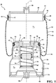
- an air suspension assembly 20 for use in a vehicle is generally shown in Fig. 1 .
- the air suspension assembly 20, as generally shown in Fig. 1 includes a top 22 disposed on a center axis A.
- the top 22 may have a cylindrical shape and an inverted U-shape in cross-section.
- a piston 24 is disposed on the center axis A spaced from the top 22.
- the piston 24 may have an inverted cup shape and an inverted U-shape in cross-section.
- a bellows 26 of an elastomeric material and having a tubular shape is disposed on the center axis A and extends annularly about the center axis A between a first end 28 and a second end 30.
- the first end 28 of the bellows 26 is secured to the top 22 and the second end 30 of the bellows 26 is secured to the piston 24 defining a first chamber 32 extending between the top 22, the piston 24, and the bellows 26.
- the bellows 26 connects the top 22 to the piston 24 forming the first chamber 32 between the top 22, the bellows 26, and the piston 24.
- the bellows 26 has an outer sleeve 34 extending from the first end 28 of the bellows 26 to an intermediate end 36 in a parallel relationship with the center axis A.
- the outer sleeve 34 may be of a tubular shape.
- the bellows 26 further includes an inner sleeve 38 extending from the intermediate end 36 of the bellows 26, in an arcuate shape, toward the center axis A and toward the first end 28 of the bellows 26, in a parallel relationship with the center axis A and the outer sleeve 34, to the second end 30 to engage the piston 24.
- the top 22 includes a plate 40 disposed on the center axis A defining an edge extending about the plate 40.
- the plate 40 may have a circular shape.
- a side wall 42 having a cylindrical shape extends perpendicularly outwardly from the edge of the plate 40 in a parallel relationship with the center axis A.
- the side wall 42 includes a plurality of protrusions 44, spaced from one another, extending outwardly from the side wall 42 and annularly about the side wall 42 in a perpendicular relationship with the center axis A to receive the first end 28 of the bellows 26.
- a first ring 46 having a circular shape is disposed on the bellows 26 at the first end 28 of the bellows 26 and extending annularly about the side wall 42 of the top 22 to secure the bellows 26 to the side walls 42 of the top 22.
- the first end 28 of the bellows 26 is sandwiched and secured by the first ring 46 between the first ring 46 and the side walls 42 of the top 22.
- the side wall 42 includes a nub 48, having a triangular shaped cross-section, disposed adjacent to the protrusions 44 and the edge of the plate 40, extending outwardly from the side wall 42 and annularly about the side wall 42 for receiving the first ring 46.
- a first bushing 50 having a cylindrical shape, is disposed on the center axis A and extending outwardly from the center axis A, away from the side wall 42, and along the center axis A for securing the air suspension assembly 20 to the vehicle.
- the piston 24 includes an upper portion 52 having a circular shape.
- the upper portion 52 has an interior surface 54 disposed in the first chamber 32 facing the top 22 and an exterior surface 56 spaced from the interior surface 54.
- a periphery 58 extends between the interior surface 54 and the exterior surface 56 and annularly about the center axis A to connect the interior surface 54 with the exterior surface 56.
- the upper portion 52 defines a bore 60, having a cylindrical shape, disposed on the center axis A and extends between the interior surface 54 and the exterior surface 56 in gas communication with the first chamber 32.
- the periphery 58 including a plurality of ridges 62, spaced from one another, and extends outwardly from the upper portion 52 in a perpendicular relationship with the center axis A to engage the second end 30 of the bellows 26.
- a second ring 64 having a circular shape is disposed at the second end 30 of the bellows 26 and extends annularly about the upper portion 52 of the piston 24 to secure the bellows 26 to the upper portion 52 of the piston 24.
- the second end 30 of the bellows 26 is sandwiched and secured by the second ring 64 between the second ring 64 and the upper portion 52 of the piston 24.
- a tab 66 is disposed adjacent to the exterior surface 56 of the upper portion 52 and extends outwardly from and annularly about the upper portion 52 to a terminal end 68 defining a shoulder disposed adjacent to the periphery 58 for receiving the second ring 64.
- the piston 24 further includes a body 70 having a bell shape attached to the upper portion 52 of the piston 24.
- the body 70 may extend from the terminal end 68 of the tab 66 and annularly about the center axis A from the terminal end 68 of the tab 66 to a proximal end 72 defining a second chamber 74 extending between the body 70 and the upper portion 52.
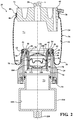
- a decoupler 76 is disposed in the bore 60 of the upper portion 52 and attached to the piston 24 in gas communication with the first chamber 32 and the second chamber 74.
- the decoupler 76 includes a partition member 78 extending transversely across the decoupler 76 to isolate the first chamber 32 from the second chamber 74 defining a first volume V 1 for the first chamber 32 and a second volume V 2 for the second chamber 74.
- the first volume V 1 extends between the partition member 78, the top 22, the piston 24, and the bellows 26.
- the second volume V 2 extends between the partition member 78 and the body 70 of the piston 24.
- the decoupler 76 compensates for changes in pressure in the first chamber 32 and the second chamber 74 by varying the first volume V 1 and the second volume V 2 .
- the decoupler 76 includes a cap portion 80 disposed adjacent to the interior surface 54, in the bore 60 of the upper portion 52, and defining a hole 82 disposed on the center axis A.
- the decoupler 76 also includes an extension portion 84, having a tubular shape, disposed in the second chamber 74 and extending annularly outwardly from the cap portion 80 to a distal end 86.
- the extension portion 84 defines a third chamber 88 in gas communication with the hole 82, the first chamber 32, and the second chamber 74 to receive the partition member 78.
- the cap portion 80 may include a collar 90 extending radially outwardly from the cap portion 80, in a perpendicular relationship with the center axis A, and annularly about the cap portion 80 to engage the interior surface 54 of the upper portion 52. It should be appreciated that the cap portion 80 can be secured to the upper portion 52 by any means, e.g. nuts and bolts or welding.
- the partition member 78 is a diaphragm 78 having a hexagonal shaped cross-section disposed on the center axis A and slidable in the third chamber 88 of the extension portion 84 isolating the first chamber 32 from the second chamber 74.
- the diaphragm 78 also includes a projection 92 extending radially outwardly from the diaphragm 78 and about the diaphragm 78 in a perpendicular relationship to the center axis A abutting the extension portion 84 of the decoupler 76.
- a Teflon band may be disposed annularly about the projection 92 sandwiched between the projection 92 and the extension portion 84 of the decoupler 76 for facilitating with the sliding movement of the diaphragm 78 inside the extension portion 84.
- a plurality of retaining members 94, 96 including a first retaining member 94 and a second retaining member 96 are disposed in the third chamber 88, spaced apart from one another, and sandwiching the diaphragm 78 between the retaining members 94, 96 to allow the diaphragm 78 to move between a first position and a second position.
- the body 70 of the piston 24 may include a base 98 having a circular shape disposed on the center axis A and attached to the proximal end 72 of the body 70 to close the second chamber 74.
- a second bushing 100 extends outwardly from the base 98 opposite the first bushing 50 along the center axis A for securing the air suspension assembly 20 to the vehicle.
- the partition member 78 is a diaphragm 78 made from elastomeric material and flexible between the first position and the second position.
- the diaphragm 78 is disposed on the center axis A and secured in the third chamber 88 of the extension portion 84 isolating the first chamber 32 from the second chamber 74.
- the decoupler 76 includes a first cover 102 and a second cover 104.
- the first cover 102 having a tubular shape, is disposed between the diaphragm 78 and the cap portion 80.
- the second cover 104 having a tubular shape, is disposed spaced from the first cover 102 between the diaphragm 78 and the distal end 86 of the extension portion 84 to secure the diaphragm 78 between the first cover 102 and the second cover 104.
- the diaphragm 78 is sandwiched between the first cover 102 and the second cover 104.
- the first cover 102 includes a first disk 106 having a circular shape and an arcuate shaped cross-section with the first cover 102 bowing away from the diaphragm 78.
- the first disk 106 defines a plurality of first orifices 108, spaced from one another, in gas communication with the first chamber 32 to allow gas to flow through the first disk 106.
- the second cover 104 includes a second disk 110 having a circular shape and an arcuate shaped cross-section with the second cover 104 bowing away from the diaphragm 78 and the first disk 106.
- the second cover 104 defines a plurality of second orifices 112, spaced from one another, in gas communication with the second chamber 74 to allow gas to flow through the second disk 110.
- a rod 126 is disposed on the center axis A and in the third chamber 88.
- the rod 126 extends through the conduit 124 of the sliding guide 116 between a first rod end 128 disposed in the first chamber 32 and a second rod end 130 disposed in the second chamber 74.
- a first divider 132 of elastomeric material having a U-shaped cross-section, is disposed in the third chamber 88 extending between the first sleeve end 120 and the cap portion 80.
- a second divider 134 of elastomeric material, having an inverted U-shape cross-section, is disposed in the third chamber 88 extending between the second sleeve end 122 and the distal end 86 of the extension portion 84.
- the first rod end 128 includes a flange 136 extending radially outwardly from the first rod end 128 and perpendicular to the center axis A.
- the body 70 of the piston 24 may include a bottom portion 114, having a T-shaped cross-section, disposed on the center axis A and attached to the proximal end 72 of the body 70 to close the second chamber 74.
- the bottom portion 114 defines a cavity 115 disposed in gas communication with the second chamber 74 expanding the second volume V 2 to between the partition member 78, the body 70 and the bottom portion 114.
- the bottom portion 114 may also include a second bushing 100 extending outwardly from the bottom portion 114, in an opposite direction of the first bushing 50, along the center axis A for securing the air suspension assembly 20 to the vehicle.
- a rod guide 138 having a U-shape in cross-section, is disposed in the second chamber 74 and extends annularly about the center axis A between the bottom portion 114 and the distal end 86 of the extension portion 84.
- the rod guide 138 defines a center aperture 140 disposed on the center axis A for receiving the second rod end 130 and a plurality of pockets 142, each having a circular shape, disposed about and spaced from the center aperture 140 and for allowing gas communication between the third chamber 88 and the cavity 115.
- a fastener 144 e.g. a nut, is disposed in the cavity 115 and secured to the second rod end 130.
- a plurality of resilient members 146, 148 including a first resilient member 146 of a spring is disposed in the first chamber 32 and extending about the rod 126 between the flange 136 at the first rod end 128 and the sleeve 118.
- the plurality of resilient members 146, 148 includes a second resilient member 148 of a spring disposed in the second chamber 74 and extending about the rod 126 between the rod guide 138 and the sleeve 118 sandwiching the sleeve 118 between the first resilient member 146 and the second resilient member 148.
- the air suspension assembly 20 includes a first housing 150 having a cylindrical shape extending along a center axis A and between a first opened end 152 and a first closed end 154.
- the first housing 150 defines a first compartment 156 extending along the center axis A between the first opened end 152 and the first closed end 154.
- a top 22 having a generally cylindrical shape is disposed at the first opened end 152 of the first housing 150.
- a piston 24, having a tubular shape, is disposed in the first compartment 156 on the center axis A and adjacent to the first closed end 154 of the first housing 150.
- the first end 28 of the bellows 26 is secured to the top 22 and the second end 30 of the bellows 26 is secured to the piston 24 defining a first chamber 32 between the top 22 and the piston 24 and the first closed end 154 of the first housing 150.
- the bellows 26 includes an outer sleeve 34, having a tubular shape, extending from the first end 28 of the bellows 26 to an intermediate end 36 in a parallel relationship with the center axis A.
- An inner sleeve 38 extends from the intermediate end 36 of the bellows 26, in an arcuate shape, toward the center axis A and toward the first end 28 of the bellows 26 in a parallel relationship with the center axis A and the outer sleeve 34 to the second end 30 to engage the piston 24.
- a crimp ring 158 having a circular shape is disposed in the first chamber 32 and adjacent to the first opened end 152 of the first housing 150. The crimp ring 158 abuts the bellows 26 to secure the bellows 26 to the first housing 150 in the first compartment 156 to prevent outer sleeve 34 of the bellows 26 from collapsing in the first compartment 156.
- the top 22 includes a plate 40 and a side wall 42 having a cylindrical shape extending perpendicularly outwardly from the plate 40 parallel to the center axis A.
- the side wall 42 defines a plurality of protrusions 44, spaced from one another, extending annularly outwardly from the side wall 42 perpendicular to the center axis A spaced from one another to engage the first end 28 of the bellows 26.
- a first ring 46 having a circular shape is disposed on the bellows 26 at the first end 28 of the bellows 26 and extending annularly about the side wall 42 of the top 22 to secure the bellows 26 to the side walls 42 of the top 22.
- the piston 24 includes an upper portion 52 having a circular shape.
- the upper portion 52 includes an interior surface 54 disposed in the first chamber 32 facing the top 22 and an exterior surface 56 spaced from the interior surface 54.
- a periphery 58 extends between the interior surface 54 and the exterior surface 56 and annularly about the center axis A to connect the interior surface 54 with the exterior surface 56.
- the upper portion 52 further defines a bore 60 having a cylindrical shape disposed on the center axis A in gas communication with the first chamber 32 and extending between the interior surface 54 and the exterior surface 56.
- a second ring 64 having a circular shape is disposed on the bellows 26 at the second end 30 of the bellows 26 and extending annularly about the upper portion 52 of the piston 24 to secure the bellows 26 to the upper portion 52 of the piston 24.
- the piston 24 further includes a body 70 of tubular shape extending outwardly from the upper portion 52 and annularly about the center axis A to a proximal end 72 adjacent to the first closed end 154 defining a second chamber 74 between the body 70 and the upper portion 52.
- a second housing 160 having a cylindrical shape, spaced from the first housing 150, extends between a second opened end 162 and a second closed end 164 defining a second compartment 166 between the second opened end 162 and the second closed end 164.
- a pipe 168 having a tubular shape, defines a channel 170 extending between the top 22 and the second opened end 162 of the second housing 160 to connect the second housing 160 with the first chamber 32 and allow gas communication between the first chamber 32 and the second compartment 166 of the second housing 160.
- a decoupler 76 is disposed in the second compartment 166 and attached to the second opened end 162 of the second housing 160 and disposed in gas communication with the channel 170.
- the decoupler 76 includes a partition member 78 extending transversely across the decoupler 76 isolating the first chamber 32 from the second compartment 166 defining a first volume V 1 for the first chamber 32 and a second volume V 2 for the second compartment 166.
- the first volume V 1 extends between the partition member 78, the top 22, the piston 24, the first housing 150, and the bellows 26.
- the second volume V 2 extends between the partition member 78 and the second housing 160 of the piston 24.
- the decoupler 76 compensates for changes in pressure in the first chamber 32 and the second chamber 74 by varying the first volume V 1 and the second volume V 2 .
- the decoupler 76 includes a cap portion 80 defining a hole 82 and attached to the second opened end 162 of the second housing 160.
- An extension portion 84 having a tubular shape, is disposed in the second compartment 166 and extending annularly outwardly from the cap portion 80 to a distal end 86 defining a third chamber 88 in gas communication with the channel 170 and the first chamber 32 and the second compartment 166 to receive the partition member 78.
- the cap portion 80 includes a collar 90 extending radially outwardly from the cap portion 80, annularly about the cap portion 80, and in a perpendicular relationship with the center axis A to engage the second opened end 162 of the second housing 160. It should be appreciated that the cap portion 80 may be secured to the second housing 160 using any means, e.g. nuts and bolts or welding.
- the first position is defined as being adjacent to the cap portion 80 and the second position is defined as adjacent to the distal end 86 of the extension portion 84 to provide a soft stiffness rate under low stroke and higher stiffness rate under larger strokes.
- the diaphragm 78 is sandwiched between the first retaining member 94 and the second retaining member 96 and in the third chamber 88 of the extension portion 84 between the first position and the second position.
- the first retaining member 94 may be a spring disposed in the third chamber 88 extending between the cap portion 80 and the diaphragm 78.
- the second retaining member 96 may also be a spring disposed in the third chamber 88 extending between the diaphragm 78 and the distal end 86 of the extension portion 84.
Landscapes
- Engineering & Computer Science (AREA)
- Mechanical Engineering (AREA)
- General Engineering & Computer Science (AREA)
- Physics & Mathematics (AREA)
- Fluid Mechanics (AREA)
- Fluid-Damping Devices (AREA)
- Vehicle Body Suspensions (AREA)
- Vibration Prevention Devices (AREA)
Priority Applications (1)
| Application Number | Priority Date | Filing Date | Title |
|---|---|---|---|
| PL17001578T PL3299193T3 (pl) | 2016-09-22 | 2017-09-22 | Pneumatyczny zespół zawieszenia |
Applications Claiming Priority (2)
| Application Number | Priority Date | Filing Date | Title |
|---|---|---|---|
| US201662398131P | 2016-09-22 | 2016-09-22 | |
| US15/671,135 US10525785B2 (en) | 2016-09-22 | 2017-08-07 | Air suspension assembly |
Publications (3)
| Publication Number | Publication Date |
|---|---|
| EP3299193A2 EP3299193A2 (en) | 2018-03-28 |
| EP3299193A3 EP3299193A3 (en) | 2018-06-13 |
| EP3299193B1 true EP3299193B1 (en) | 2020-04-15 |
Family
ID=59968880
Family Applications (1)
| Application Number | Title | Priority Date | Filing Date |
|---|---|---|---|
| EP17001578.8A Active EP3299193B1 (en) | 2016-09-22 | 2017-09-22 | An air suspension assembly |
Country Status (6)
| Country | Link |
|---|---|
| US (1) | US10525785B2 (pl) |
| EP (1) | EP3299193B1 (pl) |
| JP (1) | JP6486432B2 (pl) |
| CN (1) | CN107512145B (pl) |
| ES (1) | ES2802537T3 (pl) |
| PL (1) | PL3299193T3 (pl) |
Families Citing this family (13)
| Publication number | Priority date | Publication date | Assignee | Title |
|---|---|---|---|---|
| CN108839529B (zh) * | 2018-07-04 | 2019-03-26 | 湖南工学院 | 一种主动式可变容积空气悬架及其控制方法 |
| CN108749506B (zh) * | 2018-07-04 | 2019-03-26 | 湖南工学院 | 一种互联式可变容积空气悬架及其控制方法 |
| US11433726B2 (en) | 2019-04-15 | 2022-09-06 | ILJIN USA Corporation | Air springs and methods for making the same |
| US11459002B2 (en) * | 2019-09-18 | 2022-10-04 | Transportation Ip Holdings, Llc | Methods and systems for dynamic weight management |
| CN112879485B (zh) * | 2020-04-27 | 2022-11-25 | 北京京西重工有限公司 | 空气悬架组件和用于空气悬架组件的波纹管 |
| US11668364B2 (en) * | 2020-11-25 | 2023-06-06 | Beijingwest Industries Co., Ltd | Gas cup for a damper assembly and a damper assembly |
| US12442429B2 (en) | 2021-05-12 | 2025-10-14 | Vorsprung Technologies, Ltd. | High dynamic range suspension apparatus with selective fluid pressure communication |
| CN113090697B (zh) * | 2021-05-14 | 2025-05-06 | 浙江孔辉汽车科技股份有限公司 | 一种空气弹簧 |
| CN113173046B (zh) * | 2021-05-18 | 2022-10-28 | 贵州詹阳动力重工有限公司 | 一种水平调节装置及轮式多用工程车 |
| MX2024001805A (es) * | 2021-08-27 | 2024-02-28 | Hendrickson Usa Llc | Muelle neumatico de amortiguacion para sistemas de eje/suspension de vehiculos de trabajo pesado. |
| CN114033826B (zh) * | 2021-12-14 | 2025-08-26 | 浙江孔辉汽车科技股份有限公司 | 空气弹簧 |
| CN114962522A (zh) * | 2022-04-11 | 2022-08-30 | 中国第一汽车股份有限公司 | 一种变刚度空气弹簧 |
| US12291072B2 (en) * | 2022-08-30 | 2025-05-06 | DRiV Automotive Inc. | Air-spring assembly |
Family Cites Families (34)
| Publication number | Priority date | Publication date | Assignee | Title |
|---|---|---|---|---|
| NL112766C (pl) | 1959-04-24 | |||
| JPS571843A (en) | 1980-06-04 | 1982-01-07 | Hitachi Ltd | Air spring |
| JPH03177633A (ja) | 1989-09-29 | 1991-08-01 | Bridgestone Corp | 空気ばね |
| DE4124516A1 (de) | 1990-09-07 | 1992-03-26 | Iveco Magirus | Mehrstufige luftfeder, insbesondere fuer eine luftgefederte fahrzeugachse eines nutzfahrzeuges |
| JPH0577638U (ja) | 1992-03-24 | 1993-10-22 | 日産ディーゼル工業株式会社 | 空気ばね装置 |
| JPH0577639U (ja) | 1992-03-25 | 1993-10-22 | 日産ディーゼル工業株式会社 | 空気ばね装置 |
| DE4300669C1 (de) | 1993-01-13 | 1994-08-18 | Continental Ag | Luftfeder mit einem elastomeren Luftfederbalg und einem Zusatzvolumen |
| JP2881546B2 (ja) | 1994-04-14 | 1999-04-12 | 日野自動車工業株式会社 | エアスプリング装置 |
| SE513416C2 (sv) | 1997-12-18 | 2000-09-11 | Volvo Lastvagnar Ab | Förfarande för höjning och sänkning av ett fordonschassi |
| US6374966B1 (en) | 1998-12-04 | 2002-04-23 | Lillbacka Jetair Oy | Shock absorber assembly |
| US20040026836A1 (en) | 2002-08-07 | 2004-02-12 | Brookes Graham R. | Vehicle suspension system |
| DE102004059764C5 (de) | 2004-12-11 | 2013-06-06 | Continental Teves Ag & Co. Ohg | Luftfeder- und Dämpfereinheit |
| JP2009154547A (ja) | 2007-12-25 | 2009-07-16 | Nissan Diesel Motor Co Ltd | 空気ばね式懸架装置及びばね定数切換え制御方法 |
| US8403115B2 (en) | 2008-01-11 | 2013-03-26 | Penske Racing Shocks | Dual rate gas spring shock absorber |
| US8844912B2 (en) | 2008-04-08 | 2014-09-30 | Knorr-Bremse Systeme Fuer Nutzfahrzeuge Gmbh | Shock absorber having compressible fluid |
| JP5307486B2 (ja) | 2008-09-16 | 2013-10-02 | 株式会社ブリヂストン | 空気ばね |
| DE102009011414A1 (de) | 2009-03-03 | 2010-09-09 | Zf Friedrichshafen Ag | Feder-Dämpfer-Einheit für Fahrwerke von Fahrzeugen |
| DE102009015939A1 (de) | 2009-04-02 | 2010-12-16 | Knorr-Bremse Systeme für Nutzfahrzeuge GmbH | Dämpferkompressor und Verfahren zum Erzeugen von Druckluft durch eine Dämpfung einer Relativbewegung zwischen einer Achse und einem Chassis eines Fahrzeugs |
| US9011414B2 (en) * | 2009-04-04 | 2015-04-21 | Adam Judd Hansen | Systems and methods for hernia repair |
| DE102009002617A1 (de) | 2009-04-24 | 2010-10-28 | Zf Friedrichshafen Ag | Luftfeder-Dämpfer |
| DE102010014559A1 (de) | 2010-04-10 | 2011-10-13 | Audi Ag | Luftfeder |
| BR112013005318B1 (pt) | 2010-09-10 | 2021-05-11 | Hendrickson Usa, L.L.C. | mola pneumática |
| DE102010040980B4 (de) | 2010-09-17 | 2014-04-03 | Saf-Holland Gmbh | Luftfeder |
| US9630469B2 (en) | 2010-10-18 | 2017-04-25 | Firestone Industrial Products Company, Llc | Gas spring and gas damper assembly and method |
| DE102011086909A1 (de) | 2011-02-08 | 2012-08-09 | Continental Teves Ag & Co. Ohg | Luftfederbein für ein Fahrzeug |
| DE102011050103A1 (de) | 2011-05-04 | 2012-11-08 | Contitech Luftfedersysteme Gmbh | Abrollkolben für einen Luftfederrollbalg |
| DE102011112130A1 (de) | 2011-09-01 | 2013-03-07 | Audi Ag | Luftfedervorrichtung für ein Kraftfahrzeug |
| MX350149B (es) | 2011-10-05 | 2017-08-29 | Firestone Ind Products Co Llc | Montaje de amortiguador de gas y muelle de gas y método. |
| DE102011115986A1 (de) | 2011-10-14 | 2013-04-18 | Audi Ag | Luftfeder für ein Kraftfahrzeug |
| WO2013075036A1 (en) | 2011-11-16 | 2013-05-23 | Firestone Industrial Products Company, Llc | Axial clutch assembly as well as gas spring and gas damper assembly and method including same |
| DE102012103358A1 (de) | 2012-04-18 | 2013-10-24 | Contitech Luftfedersysteme Gmbh | Abrollkolben für einen Luftfederrollbalg |
| US9259985B2 (en) | 2012-09-07 | 2016-02-16 | Firestone Industrial Products Company, Llc | Gas spring and damper assemblies and methods |
| US9951837B2 (en) | 2013-05-22 | 2018-04-24 | Firestone Industrial Products Company, Llc | End member and gas spring assembly including same |
| DE102013107826A1 (de) * | 2013-07-23 | 2015-01-29 | Dr. Ing. H.C. F. Porsche Aktiengesellschaft | Luftfeder für ein Kraftfahrzeug |
-
2017
- 2017-08-07 US US15/671,135 patent/US10525785B2/en active Active
- 2017-08-15 CN CN201710696168.4A patent/CN107512145B/zh active Active
- 2017-09-15 JP JP2017177213A patent/JP6486432B2/ja active Active
- 2017-09-22 ES ES17001578T patent/ES2802537T3/es active Active
- 2017-09-22 PL PL17001578T patent/PL3299193T3/pl unknown
- 2017-09-22 EP EP17001578.8A patent/EP3299193B1/en active Active
Non-Patent Citations (1)
| Title |
|---|
| None * |
Also Published As
| Publication number | Publication date |
|---|---|
| JP6486432B2 (ja) | 2019-03-20 |
| CN107512145B (zh) | 2019-06-28 |
| PL3299193T3 (pl) | 2020-10-19 |
| EP3299193A3 (en) | 2018-06-13 |
| EP3299193A2 (en) | 2018-03-28 |
| US10525785B2 (en) | 2020-01-07 |
| JP2018048736A (ja) | 2018-03-29 |
| US20180079274A1 (en) | 2018-03-22 |
| ES2802537T3 (es) | 2021-01-20 |
| CN107512145A (zh) | 2017-12-26 |
Similar Documents
| Publication | Publication Date | Title |
|---|---|---|
| EP3299193B1 (en) | An air suspension assembly | |
| US6691989B1 (en) | Variable rate air spring assembly | |
| CN114302816B (zh) | 安装组件以及包括这种安装组件的气弹簧和阻尼器组件以及悬架系统 | |
| US9370984B2 (en) | Gas spring and gas damper assemblies and methods of assembly | |
| EP3140564B1 (en) | Gas spring and gas damper assemblies as well as suspension systems including same | |
| US11661991B2 (en) | Gas spring and gas damper assemblies as well as suspension systems and methods of assembly | |
| JPH03234938A (ja) | 振動減衰装置 | |
| US8177201B2 (en) | Very high damping mount with bolt-through construction | |
| EP3904133B1 (en) | Air suspension assembly | |
| US6199837B1 (en) | Thermoplastic elastomer air spring | |
| EP3620682B1 (en) | Mr mount with a dual hardness rubber decoupler | |
| EP3477150B1 (en) | Hydraulic mount apparatus | |
| US6942201B2 (en) | Volume reducing bead plate for air spring | |
| US20200156429A1 (en) | End mount assemblies as well as gas spring and damper assemblies including same | |
| US20060151929A1 (en) | Elastomeric/hydraulic vibration isolator with adjustable damping | |
| US7128311B2 (en) | Active vibration damping actuator and active damping apparatus using the same | |
| US10465815B2 (en) | Extended stroke, high flow, valve and the assembly made therewith | |
| CN113330229B (zh) | 气弹簧和阻尼器组件以及包括其的悬架系统 | |
| EP3620683B1 (en) | Mr mount apparatus using a polymeric sheet decoupler | |
| WO2018125662A1 (en) | End member assemblies as well as gas spring and gas damper assemblies, suspension systems and methods | |
| CN114321252B (zh) | 空气弹簧组件及汽车 | |
| EP4006376B1 (en) | A gas cup for a damper assembly and a damper assembly | |
| JP2007298081A (ja) | 流体封入式防振装置 | |
| WO2015195637A1 (en) | End members and gas spring assemblies including same |
Legal Events
| Date | Code | Title | Description |
|---|---|---|---|
| PUAI | Public reference made under article 153(3) epc to a published international application that has entered the european phase |
Free format text: ORIGINAL CODE: 0009012 |
|
| STAA | Information on the status of an ep patent application or granted ep patent |
Free format text: STATUS: THE APPLICATION HAS BEEN PUBLISHED |
|
| AK | Designated contracting states |
Kind code of ref document: A2 Designated state(s): AL AT BE BG CH CY CZ DE DK EE ES FI FR GB GR HR HU IE IS IT LI LT LU LV MC MK MT NL NO PL PT RO RS SE SI SK SM TR |
|
| AX | Request for extension of the european patent |
Extension state: BA ME |
|
| RIN1 | Information on inventor provided before grant (corrected) |
Inventor name: ROSE, IAIN Inventor name: FANELLI, DOMINIQUE Inventor name: MARCHAND, JOCELYN |
|
| PUAL | Search report despatched |
Free format text: ORIGINAL CODE: 0009013 |
|
| AK | Designated contracting states |
Kind code of ref document: A3 Designated state(s): AL AT BE BG CH CY CZ DE DK EE ES FI FR GB GR HR HU IE IS IT LI LT LU LV MC MK MT NL NO PL PT RO RS SE SI SK SM TR |
|
| AX | Request for extension of the european patent |
Extension state: BA ME |
|
| RIC1 | Information provided on ipc code assigned before grant |
Ipc: B60G 11/27 20060101AFI20180508BHEP Ipc: F16F 9/512 20060101ALI20180508BHEP Ipc: B60G 17/048 20060101ALI20180508BHEP Ipc: B60G 17/052 20060101ALI20180508BHEP Ipc: B60G 11/58 20060101ALI20180508BHEP Ipc: F16F 9/04 20060101ALI20180508BHEP Ipc: F16F 9/05 20060101ALI20180508BHEP |
|
| STAA | Information on the status of an ep patent application or granted ep patent |
Free format text: STATUS: REQUEST FOR EXAMINATION WAS MADE |
|
| 17P | Request for examination filed |
Effective date: 20181213 |
|
| RBV | Designated contracting states (corrected) |
Designated state(s): AL AT BE BG CH CY CZ DE DK EE ES FI FR GB GR HR HU IE IS IT LI LT LU LV MC MK MT NL NO PL PT RO RS SE SI SK SM TR |
|
| GRAP | Despatch of communication of intention to grant a patent |
Free format text: ORIGINAL CODE: EPIDOSNIGR1 |
|
| STAA | Information on the status of an ep patent application or granted ep patent |
Free format text: STATUS: GRANT OF PATENT IS INTENDED |
|
| INTG | Intention to grant announced |
Effective date: 20191029 |
|
| RAP1 | Party data changed (applicant data changed or rights of an application transferred) |
Owner name: BEIJINGWEST INDUSTRIES CO., LTD. |
|
| GRAS | Grant fee paid |
Free format text: ORIGINAL CODE: EPIDOSNIGR3 |
|
| GRAA | (expected) grant |
Free format text: ORIGINAL CODE: 0009210 |
|
| STAA | Information on the status of an ep patent application or granted ep patent |
Free format text: STATUS: THE PATENT HAS BEEN GRANTED |
|
| AK | Designated contracting states |
Kind code of ref document: B1 Designated state(s): AL AT BE BG CH CY CZ DE DK EE ES FI FR GB GR HR HU IE IS IT LI LT LU LV MC MK MT NL NO PL PT RO RS SE SI SK SM TR |
|
| REG | Reference to a national code |
Ref country code: CH Ref legal event code: EP |
|
| REG | Reference to a national code |
Ref country code: DE Ref legal event code: R096 Ref document number: 602017014601 Country of ref document: DE |
|
| REG | Reference to a national code |
Ref country code: IE Ref legal event code: FG4D |
|
| REG | Reference to a national code |
Ref country code: AT Ref legal event code: REF Ref document number: 1256847 Country of ref document: AT Kind code of ref document: T Effective date: 20200515 |
|
| REG | Reference to a national code |
Ref country code: RO Ref legal event code: EPE |
|
| REG | Reference to a national code |
Ref country code: NL Ref legal event code: MP Effective date: 20200415 |
|
| REG | Reference to a national code |
Ref country code: LT Ref legal event code: MG4D |
|
| PG25 | Lapsed in a contracting state [announced via postgrant information from national office to epo] |
Ref country code: LT Free format text: LAPSE BECAUSE OF FAILURE TO SUBMIT A TRANSLATION OF THE DESCRIPTION OR TO PAY THE FEE WITHIN THE PRESCRIBED TIME-LIMIT Effective date: 20200415 Ref country code: PT Free format text: LAPSE BECAUSE OF FAILURE TO SUBMIT A TRANSLATION OF THE DESCRIPTION OR TO PAY THE FEE WITHIN THE PRESCRIBED TIME-LIMIT Effective date: 20200817 Ref country code: NL Free format text: LAPSE BECAUSE OF FAILURE TO SUBMIT A TRANSLATION OF THE DESCRIPTION OR TO PAY THE FEE WITHIN THE PRESCRIBED TIME-LIMIT Effective date: 20200415 Ref country code: FI Free format text: LAPSE BECAUSE OF FAILURE TO SUBMIT A TRANSLATION OF THE DESCRIPTION OR TO PAY THE FEE WITHIN THE PRESCRIBED TIME-LIMIT Effective date: 20200415 Ref country code: NO Free format text: LAPSE BECAUSE OF FAILURE TO SUBMIT A TRANSLATION OF THE DESCRIPTION OR TO PAY THE FEE WITHIN THE PRESCRIBED TIME-LIMIT Effective date: 20200715 Ref country code: GR Free format text: LAPSE BECAUSE OF FAILURE TO SUBMIT A TRANSLATION OF THE DESCRIPTION OR TO PAY THE FEE WITHIN THE PRESCRIBED TIME-LIMIT Effective date: 20200716 Ref country code: SE Free format text: LAPSE BECAUSE OF FAILURE TO SUBMIT A TRANSLATION OF THE DESCRIPTION OR TO PAY THE FEE WITHIN THE PRESCRIBED TIME-LIMIT Effective date: 20200415 Ref country code: IS Free format text: LAPSE BECAUSE OF FAILURE TO SUBMIT A TRANSLATION OF THE DESCRIPTION OR TO PAY THE FEE WITHIN THE PRESCRIBED TIME-LIMIT Effective date: 20200815 |
|
| REG | Reference to a national code |
Ref country code: AT Ref legal event code: MK05 Ref document number: 1256847 Country of ref document: AT Kind code of ref document: T Effective date: 20200415 |
|
| PG25 | Lapsed in a contracting state [announced via postgrant information from national office to epo] |
Ref country code: LV Free format text: LAPSE BECAUSE OF FAILURE TO SUBMIT A TRANSLATION OF THE DESCRIPTION OR TO PAY THE FEE WITHIN THE PRESCRIBED TIME-LIMIT Effective date: 20200415 Ref country code: RS Free format text: LAPSE BECAUSE OF FAILURE TO SUBMIT A TRANSLATION OF THE DESCRIPTION OR TO PAY THE FEE WITHIN THE PRESCRIBED TIME-LIMIT Effective date: 20200415 Ref country code: HR Free format text: LAPSE BECAUSE OF FAILURE TO SUBMIT A TRANSLATION OF THE DESCRIPTION OR TO PAY THE FEE WITHIN THE PRESCRIBED TIME-LIMIT Effective date: 20200415 Ref country code: BG Free format text: LAPSE BECAUSE OF FAILURE TO SUBMIT A TRANSLATION OF THE DESCRIPTION OR TO PAY THE FEE WITHIN THE PRESCRIBED TIME-LIMIT Effective date: 20200715 |
|
| PG25 | Lapsed in a contracting state [announced via postgrant information from national office to epo] |
Ref country code: AL Free format text: LAPSE BECAUSE OF FAILURE TO SUBMIT A TRANSLATION OF THE DESCRIPTION OR TO PAY THE FEE WITHIN THE PRESCRIBED TIME-LIMIT Effective date: 20200415 |
|
| REG | Reference to a national code |
Ref country code: DE Ref legal event code: R097 Ref document number: 602017014601 Country of ref document: DE |
|
| REG | Reference to a national code |
Ref country code: ES Ref legal event code: FG2A Ref document number: 2802537 Country of ref document: ES Kind code of ref document: T3 Effective date: 20210120 |
|
| PG25 | Lapsed in a contracting state [announced via postgrant information from national office to epo] |
Ref country code: AT Free format text: LAPSE BECAUSE OF FAILURE TO SUBMIT A TRANSLATION OF THE DESCRIPTION OR TO PAY THE FEE WITHIN THE PRESCRIBED TIME-LIMIT Effective date: 20200415 Ref country code: SM Free format text: LAPSE BECAUSE OF FAILURE TO SUBMIT A TRANSLATION OF THE DESCRIPTION OR TO PAY THE FEE WITHIN THE PRESCRIBED TIME-LIMIT Effective date: 20200415 Ref country code: EE Free format text: LAPSE BECAUSE OF FAILURE TO SUBMIT A TRANSLATION OF THE DESCRIPTION OR TO PAY THE FEE WITHIN THE PRESCRIBED TIME-LIMIT Effective date: 20200415 Ref country code: DK Free format text: LAPSE BECAUSE OF FAILURE TO SUBMIT A TRANSLATION OF THE DESCRIPTION OR TO PAY THE FEE WITHIN THE PRESCRIBED TIME-LIMIT Effective date: 20200415 |
|
| PLBE | No opposition filed within time limit |
Free format text: ORIGINAL CODE: 0009261 |
|
| STAA | Information on the status of an ep patent application or granted ep patent |
Free format text: STATUS: NO OPPOSITION FILED WITHIN TIME LIMIT |
|
| PG25 | Lapsed in a contracting state [announced via postgrant information from national office to epo] |
Ref country code: SK Free format text: LAPSE BECAUSE OF FAILURE TO SUBMIT A TRANSLATION OF THE DESCRIPTION OR TO PAY THE FEE WITHIN THE PRESCRIBED TIME-LIMIT Effective date: 20200415 |
|
| 26N | No opposition filed |
Effective date: 20210118 |
|
| REG | Reference to a national code |
Ref country code: CH Ref legal event code: PL |
|
| PG25 | Lapsed in a contracting state [announced via postgrant information from national office to epo] |
Ref country code: SI Free format text: LAPSE BECAUSE OF FAILURE TO SUBMIT A TRANSLATION OF THE DESCRIPTION OR TO PAY THE FEE WITHIN THE PRESCRIBED TIME-LIMIT Effective date: 20200415 |
|
| REG | Reference to a national code |
Ref country code: BE Ref legal event code: MM Effective date: 20200930 |
|
| PG25 | Lapsed in a contracting state [announced via postgrant information from national office to epo] |
Ref country code: LU Free format text: LAPSE BECAUSE OF NON-PAYMENT OF DUE FEES Effective date: 20200922 |
|
| PG25 | Lapsed in a contracting state [announced via postgrant information from national office to epo] |
Ref country code: BE Free format text: LAPSE BECAUSE OF NON-PAYMENT OF DUE FEES Effective date: 20200930 Ref country code: CH Free format text: LAPSE BECAUSE OF NON-PAYMENT OF DUE FEES Effective date: 20200930 Ref country code: IE Free format text: LAPSE BECAUSE OF NON-PAYMENT OF DUE FEES Effective date: 20200922 Ref country code: LI Free format text: LAPSE BECAUSE OF NON-PAYMENT OF DUE FEES Effective date: 20200930 |
|
| PG25 | Lapsed in a contracting state [announced via postgrant information from national office to epo] |
Ref country code: TR Free format text: LAPSE BECAUSE OF FAILURE TO SUBMIT A TRANSLATION OF THE DESCRIPTION OR TO PAY THE FEE WITHIN THE PRESCRIBED TIME-LIMIT Effective date: 20200415 Ref country code: MT Free format text: LAPSE BECAUSE OF FAILURE TO SUBMIT A TRANSLATION OF THE DESCRIPTION OR TO PAY THE FEE WITHIN THE PRESCRIBED TIME-LIMIT Effective date: 20200415 Ref country code: CY Free format text: LAPSE BECAUSE OF FAILURE TO SUBMIT A TRANSLATION OF THE DESCRIPTION OR TO PAY THE FEE WITHIN THE PRESCRIBED TIME-LIMIT Effective date: 20200415 |
|
| PG25 | Lapsed in a contracting state [announced via postgrant information from national office to epo] |
Ref country code: MK Free format text: LAPSE BECAUSE OF FAILURE TO SUBMIT A TRANSLATION OF THE DESCRIPTION OR TO PAY THE FEE WITHIN THE PRESCRIBED TIME-LIMIT Effective date: 20200415 Ref country code: MC Free format text: LAPSE BECAUSE OF FAILURE TO SUBMIT A TRANSLATION OF THE DESCRIPTION OR TO PAY THE FEE WITHIN THE PRESCRIBED TIME-LIMIT Effective date: 20200415 |
|
| PGFP | Annual fee paid to national office [announced via postgrant information from national office to epo] |
Ref country code: DE Payment date: 20250730 Year of fee payment: 9 |
|
| PGFP | Annual fee paid to national office [announced via postgrant information from national office to epo] |
Ref country code: IT Payment date: 20250825 Year of fee payment: 9 Ref country code: PL Payment date: 20250805 Year of fee payment: 9 |
|
| PGFP | Annual fee paid to national office [announced via postgrant information from national office to epo] |
Ref country code: GB Payment date: 20250731 Year of fee payment: 9 |
|
| PGFP | Annual fee paid to national office [announced via postgrant information from national office to epo] |
Ref country code: FR Payment date: 20250808 Year of fee payment: 9 |
|
| PGFP | Annual fee paid to national office [announced via postgrant information from national office to epo] |
Ref country code: CZ Payment date: 20250905 Year of fee payment: 9 |
|
| PGFP | Annual fee paid to national office [announced via postgrant information from national office to epo] |
Ref country code: RO Payment date: 20250828 Year of fee payment: 9 |
|
| PGFP | Annual fee paid to national office [announced via postgrant information from national office to epo] |
Ref country code: ES Payment date: 20251015 Year of fee payment: 9 |