EP3297596B1 - Anschlussbaugruppe zum leiten einer medizinischen flüssigkeit - Google Patents
Anschlussbaugruppe zum leiten einer medizinischen flüssigkeit Download PDFInfo
- Publication number
- EP3297596B1 EP3297596B1 EP16727339.0A EP16727339A EP3297596B1 EP 3297596 B1 EP3297596 B1 EP 3297596B1 EP 16727339 A EP16727339 A EP 16727339A EP 3297596 B1 EP3297596 B1 EP 3297596B1
- Authority
- EP
- European Patent Office
- Prior art keywords
- attachment part
- piece
- sealing element
- connection
- section
- Prior art date
- Legal status (The legal status is an assumption and is not a legal conclusion. Google has not performed a legal analysis and makes no representation as to the accuracy of the status listed.)
- Active
Links
Images


Classifications
-
- A—HUMAN NECESSITIES
- A61—MEDICAL OR VETERINARY SCIENCE; HYGIENE
- A61J—CONTAINERS SPECIALLY ADAPTED FOR MEDICAL OR PHARMACEUTICAL PURPOSES; DEVICES OR METHODS SPECIALLY ADAPTED FOR BRINGING PHARMACEUTICAL PRODUCTS INTO PARTICULAR PHYSICAL OR ADMINISTERING FORMS; DEVICES FOR ADMINISTERING FOOD OR MEDICINES ORALLY; BABY COMFORTERS; DEVICES FOR RECEIVING SPITTLE
- A61J1/00—Containers specially adapted for medical or pharmaceutical purposes
- A61J1/14—Details; Accessories therefor
- A61J1/20—Arrangements for transferring or mixing fluids, e.g. from vial to syringe
- A61J1/2003—Accessories used in combination with means for transfer or mixing of fluids, e.g. for activating fluid flow, separating fluids, filtering fluid or venting
-
- A—HUMAN NECESSITIES
- A61—MEDICAL OR VETERINARY SCIENCE; HYGIENE
- A61J—CONTAINERS SPECIALLY ADAPTED FOR MEDICAL OR PHARMACEUTICAL PURPOSES; DEVICES OR METHODS SPECIALLY ADAPTED FOR BRINGING PHARMACEUTICAL PRODUCTS INTO PARTICULAR PHYSICAL OR ADMINISTERING FORMS; DEVICES FOR ADMINISTERING FOOD OR MEDICINES ORALLY; BABY COMFORTERS; DEVICES FOR RECEIVING SPITTLE
- A61J1/00—Containers specially adapted for medical or pharmaceutical purposes
- A61J1/05—Containers specially adapted for medical or pharmaceutical purposes for collecting, storing or administering blood, plasma or medical fluids ; Infusion or perfusion containers
- A61J1/10—Bag-type containers
-
- A—HUMAN NECESSITIES
- A61—MEDICAL OR VETERINARY SCIENCE; HYGIENE
- A61J—CONTAINERS SPECIALLY ADAPTED FOR MEDICAL OR PHARMACEUTICAL PURPOSES; DEVICES OR METHODS SPECIALLY ADAPTED FOR BRINGING PHARMACEUTICAL PRODUCTS INTO PARTICULAR PHYSICAL OR ADMINISTERING FORMS; DEVICES FOR ADMINISTERING FOOD OR MEDICINES ORALLY; BABY COMFORTERS; DEVICES FOR RECEIVING SPITTLE
- A61J1/00—Containers specially adapted for medical or pharmaceutical purposes
- A61J1/14—Details; Accessories therefor
- A61J1/1406—Septums, pierceable membranes
-
- A—HUMAN NECESSITIES
- A61—MEDICAL OR VETERINARY SCIENCE; HYGIENE
- A61J—CONTAINERS SPECIALLY ADAPTED FOR MEDICAL OR PHARMACEUTICAL PURPOSES; DEVICES OR METHODS SPECIALLY ADAPTED FOR BRINGING PHARMACEUTICAL PRODUCTS INTO PARTICULAR PHYSICAL OR ADMINISTERING FORMS; DEVICES FOR ADMINISTERING FOOD OR MEDICINES ORALLY; BABY COMFORTERS; DEVICES FOR RECEIVING SPITTLE
- A61J1/00—Containers specially adapted for medical or pharmaceutical purposes
- A61J1/14—Details; Accessories therefor
- A61J1/20—Arrangements for transferring or mixing fluids, e.g. from vial to syringe
- A61J1/2003—Accessories used in combination with means for transfer or mixing of fluids, e.g. for activating fluid flow, separating fluids, filtering fluid or venting
- A61J1/2006—Piercing means
- A61J1/201—Piercing means having one piercing end
-
- A—HUMAN NECESSITIES
- A61—MEDICAL OR VETERINARY SCIENCE; HYGIENE
- A61J—CONTAINERS SPECIALLY ADAPTED FOR MEDICAL OR PHARMACEUTICAL PURPOSES; DEVICES OR METHODS SPECIALLY ADAPTED FOR BRINGING PHARMACEUTICAL PRODUCTS INTO PARTICULAR PHYSICAL OR ADMINISTERING FORMS; DEVICES FOR ADMINISTERING FOOD OR MEDICINES ORALLY; BABY COMFORTERS; DEVICES FOR RECEIVING SPITTLE
- A61J1/00—Containers specially adapted for medical or pharmaceutical purposes
- A61J1/14—Details; Accessories therefor
- A61J1/20—Arrangements for transferring or mixing fluids, e.g. from vial to syringe
- A61J1/2003—Accessories used in combination with means for transfer or mixing of fluids, e.g. for activating fluid flow, separating fluids, filtering fluid or venting
- A61J1/202—Separating means
- A61J1/2027—Separating means having frangible parts
-
- A—HUMAN NECESSITIES
- A61—MEDICAL OR VETERINARY SCIENCE; HYGIENE
- A61J—CONTAINERS SPECIALLY ADAPTED FOR MEDICAL OR PHARMACEUTICAL PURPOSES; DEVICES OR METHODS SPECIALLY ADAPTED FOR BRINGING PHARMACEUTICAL PRODUCTS INTO PARTICULAR PHYSICAL OR ADMINISTERING FORMS; DEVICES FOR ADMINISTERING FOOD OR MEDICINES ORALLY; BABY COMFORTERS; DEVICES FOR RECEIVING SPITTLE
- A61J1/00—Containers specially adapted for medical or pharmaceutical purposes
- A61J1/14—Details; Accessories therefor
- A61J1/20—Arrangements for transferring or mixing fluids, e.g. from vial to syringe
- A61J1/2003—Accessories used in combination with means for transfer or mixing of fluids, e.g. for activating fluid flow, separating fluids, filtering fluid or venting
- A61J1/202—Separating means
- A61J1/2044—Separating means having slits
-
- A—HUMAN NECESSITIES
- A61—MEDICAL OR VETERINARY SCIENCE; HYGIENE
- A61J—CONTAINERS SPECIALLY ADAPTED FOR MEDICAL OR PHARMACEUTICAL PURPOSES; DEVICES OR METHODS SPECIALLY ADAPTED FOR BRINGING PHARMACEUTICAL PRODUCTS INTO PARTICULAR PHYSICAL OR ADMINISTERING FORMS; DEVICES FOR ADMINISTERING FOOD OR MEDICINES ORALLY; BABY COMFORTERS; DEVICES FOR RECEIVING SPITTLE
- A61J1/00—Containers specially adapted for medical or pharmaceutical purposes
- A61J1/14—Details; Accessories therefor
- A61J1/20—Arrangements for transferring or mixing fluids, e.g. from vial to syringe
- A61J1/2003—Accessories used in combination with means for transfer or mixing of fluids, e.g. for activating fluid flow, separating fluids, filtering fluid or venting
- A61J1/2048—Connecting means
-
- A—HUMAN NECESSITIES
- A61—MEDICAL OR VETERINARY SCIENCE; HYGIENE
- A61J—CONTAINERS SPECIALLY ADAPTED FOR MEDICAL OR PHARMACEUTICAL PURPOSES; DEVICES OR METHODS SPECIALLY ADAPTED FOR BRINGING PHARMACEUTICAL PRODUCTS INTO PARTICULAR PHYSICAL OR ADMINISTERING FORMS; DEVICES FOR ADMINISTERING FOOD OR MEDICINES ORALLY; BABY COMFORTERS; DEVICES FOR RECEIVING SPITTLE
- A61J1/00—Containers specially adapted for medical or pharmaceutical purposes
- A61J1/14—Details; Accessories therefor
- A61J1/20—Arrangements for transferring or mixing fluids, e.g. from vial to syringe
- A61J1/2096—Combination of a vial and a syringe for transferring or mixing their contents
Definitions
- the invention relates to a connection assembly for conducting a medical fluid according to the preamble of claim 1.
- connection assembly can be used, for example, on a container for medical fluids, for example in the form of a flexible bag, an ampoule or another bottle container, in order to direct a medical fluid into the container or to remove it from the container.
- a connection assembly can also be referred to as a connector for short.
- the known connector for a package containing a medical liquid is inserted into a channel-shaped recess of a connecting part of a self-sealing membrane.
- the channel-shaped recess is closed by a break-off part that can be broken off from the connecting part to release the channel-shaped recess, so that a syringe with a connecting piece can be attached to the connector.
- the membrane By attaching the syringe to the connector, the membrane can be opened so that a liquid can be pumped into or out of a container.
- a hollow body with a tip is arranged on one side of a membrane that faces away from a syringe that is attached to the membrane.
- the hollow body supports the opening of the membrane.
- a valve unit with a hollow body that supports the opening of the membrane is also available in the WO 93/11828 A1
- the document shows a needle-free valve unit with a tubular body defining an internal cavity.
- the valve unit also includes a hollow spike with a closed tip arranged in the cavity.
- the valve unit further includes an elastic silicone seal which closes the valve unit and covers the tip of the spike.
- the seal has a sealing head, a conical side wall and a lower sealing lip. The lower sealing lip is held in a clamping manner between an annular sleeve and the underside of a ring.
- Such connectors are used, for example, to create a so-called needle-free access to a container containing a medical liquid, for example a bag or a bottle, in order to fill liquid into the container or to remove it from the container via the access.
- a needle-free access enables access to the container using a conveyor device that does not have an injection needle.
- a connecting piece of a conveyor device in the form of a syringe is attached to a slotted opening of a sealing element in order to open the slotted opening and enable a flow between the conveyor device and the container.
- sealing element Even if the sealing element is already provided sterile, legal requirements may require the sealing element to be wiped or dabbed on its outside before connecting a conveyor device to the attachment. This is intended to ensure access, for example to a container, under sterile conditions.
- dab- or wipe-off connectors are available, for example, from the EP 1 470 352 B1 and the EP 1 217 284 B1 known.
- the US 2010/0298782 A1 describes an intravascular valve component having a valve housing and a flexible pressure actuable flow control valve.
- the housing includes proximal and distal housing portions connected together.
- the valve includes a slotted central valve wall and an annular flange surrounding the valve wall.
- the flange has a radially extending flange wall and a projection extending axially from the flange wall. The projection engages a portion of the valve housing to restrict radial movement of the valve relative to the housing.
- WO 98/26835 discloses a connection assembly with a deformable sealing element whose interior has a tip.
- the object of the present invention is to provide a connection assembly for conducting a medical fluid that enables a reliable hold but also a certain mobility of the sealing element. In particular, the flow should not be significantly impaired.
- a further object is to provide a connection assembly in which a sealing element can be easily wiped or dabbed for the purpose of disinfection.
- connection assembly for conveying a medical fluid. It comprises a connection piece through which a medical fluid can be conveyed, and an attachment part that can be attached to the connection piece and can be connected to a conveying device for conveying a medical fluid through the connection piece.
- the attachment piece preferably has an opening into which the connection piece engages when the attachment part is attached to the connection piece.
- the connection assembly also comprises a sealing element for sealing a transition between the connection piece and the attachment part.
- the sealing element can preferably be inserted in an insertion direction into the opening of the attachment part in such a way that when the attachment part is attached to the connection piece Attachment part, the sealing element is held between the attachment part and the connection piece.
- the interior of the sealing element is free of a body with a tip, which is intended to support the opening of the sealing element.
- the sealing element has a sealing head which, when the attachment part is attached to the connecting piece, closes the opening of the attachment part against the passage of liquid, and a body which is connected to the sealing head and which can be or is arranged in the opening at a radial distance from the attachment part.
- the sealing element When the attachment part is attached to the connecting piece, the sealing element is held between the attachment part and the connecting piece in such a way that the flange rests with its underside on a support surface of the connecting piece and its upper side is exposed at least in sections.
- the sealing element comprises a foot section which, viewed axially along the insertion direction (E), adjoins the body below the flange and, when the attachment part is attached to the connecting piece, engages in an associated recess in the connecting piece.
- the sealing element When the attachment part is attached to the connecting piece, the sealing element is held in a clamping manner between the attachment part and the connecting piece, so that a transition between the attachment part and the connecting piece is sealed in a liquid-tight manner.
- the sealing element has a shoulder that runs around the insertion direction, which projects radially outwards over the sealing head and - when the attachment part is attached to the connecting piece - rests against an associated contact surface of the attachment part. The sealing element is thus supported by the shoulder, in particular axially along the insertion direction relative to the attachment part, so that the sealing element is fixed axially relative to the attachment part via the shoulder.
- the diameter of the sealing element in the area of the shoulder is in a range of 4 mm to 10 mm, preferably 6 mm to 8 mm. Because the sealing element is supported with the shoulder on the one hand on the attachment part and via its flange and the foot section on the other hand on the connection piece, a defined, secured position of the sealing element within the opening of the attachment part can be ensured.
- the cylindrical body of the sealing element adjoins the shoulder.
- the sealing element as a whole preferably has a rotationally symmetrical shape, whereby different sections of the sealing element can have different diameters.
- the body adjoining the shoulder is arranged with radial play in the opening of the attachment part, so that there is a space around the body within the opening of the attachment part, into which the sealing element can deform when a conveying device is attached to the attachment part.
- a slot opening on the sealing head of the sealing element can be opened in a reliable manner and, in the open state, a flow between the conveying device and the connecting piece can be made possible unhindered by the sealing element.
- the flange which projects radially outwards, is connected to the body. This projects outwards beyond the body.
- the flange is held or fixed in a clamping manner between the attachment part and the connecting piece in such a way that the flange itself is not clamped.
- This indirect clamping of the flange is achieved by the sealing element being supported with the shoulder on the one hand on the attachment part and via its flange and/or the foot section on the other hand on the connecting piece.
- the flange only rests with its underside on a support surface of the connecting piece and its upper side is exposed, preferably in sections or completely.
- the sealing element is thus fixed between the attachment part and the connecting piece via the flange, with the flange preferably being arranged at an end of the body facing away from the shoulder and thus the sealing element being supported with the shoulder on one side of the body and with the flange on the other side of the body opposite the attachment part and the connecting piece.
- the diameter of the sealing element on the flange is preferably larger than on the shoulder.
- the Diameter of the flange in a range of 5 mm to 11 mm, preferably 7 mm to 9 mm.
- the sealing element still has a certain degree of mobility because the flange itself is not held in a clamped manner.
- the sealing head when connecting the syringe, the sealing head can first be pushed from the syringe connection piece downwards into the housing.
- the side wall of the sealing element can thereby move radially.
- the sealing element can then be opened by inserting the syringe connection piece into a slot opening in the sealing head.
- the radial compensating movement of the side wall can be supported by the movable arrangement of the flange.
- a radially outer section of the flange can be held in a clamped manner between a support surface of the connection piece and a projection of the attachment part that projects radially inwards into the opening when the attachment part is attached to the connection piece, for example initially.
- the projection is preferably an annular projection.
- the annular projection can extend completely or only in sections over the circumference of the sealing element. The sealing element can thus be fixed, for example completely, within the opening via the annular projection, wherein the body can be held at a radial distance from the outer wall of the attachment part surrounding the opening via the annular projection that projects radially inwards into the opening.
- the annular projection can thus, on the one hand, cause the sealing element to be clamped in sections between the attachment part and the connection piece.
- the annular projection can support the (centered) position of the sealing element within the opening with a radial distance from the wall of the attachment part surrounding the sealing element.
- the connection between the connecting piece and the attachment part can also be provided via the ring projection.
- the sealing element is convex on an outer side, which faces away from the connecting piece when the attachment part is attached to the connecting piece.
- the sealing element it is also conceivable and possible for the sealing element to be essentially flat on the outer side or concavely curved inwards.
- the outside can, in particular in a state in which a conveyor device can be connected to the attachment part, protrude outwards beyond the attachment part or be flush with a surface of the attachment part, so that before the conveyor device is attached, the outside of the sealing element can be easily accessed from the outside and wiped or dabbed for the purpose of sterilization.
- the attachment part can have a break-off piece which, in an initial state, is integrally connected to another section of the attachment part connected to the connection piece and can be removed from this section, in particular broken off, in order to connect a conveyor device to the attachment part.
- the sealing element can protrude outwards with its outside so that the outside can be wiped or dabbed from the outside.
- the connection assembly and in particular also the outside of the sealing element can be provided sterile in the initial state, ie when the break-off piece has not yet been broken off.
- the outside is formed on the sealing head of the sealing element. If, for example, a break-off piece is removed from the attachment part, essentially only the outside of the sealing element is exposed to the outside, which protrudes outwards in a convex manner, for example, and can be wiped or dabbed off in a simple, reliable manner.
- the top or outside of the sealing head preferably has a diameter in a range of 3 mm to 7 mm, preferably 4 mm to 6 mm.
- the shoulder is preferably arranged at an end of the sealing head facing away from the outside.
- no hollow body with a tip is provided which is intended to support the opening of the membrane.
- No body or hollow body with a tip is provided which is arranged inside the sealing element and is intended to support the opening of the sealing head.
- the sealing head is adjoined by a preferably cylindrical section which merges into the shoulder which projects radially outwards beyond the section.
- This section preferably has a larger diameter than the sealing head.
- the cylindrically shaped body can adjoin the shoulder, with the shoulder projecting radially outwards beyond the body.
- the body can have a recess in its outside at a transition to the flange, preferably provided by or as a step. In particular, there is only a single step in the body. This can support the radial compensating movement of the sealing element when connecting the syringe, for example by a type of bulging.
- the recess can have a substantially straight bottom.
- the recess can have a cuboid-like cross section. The bottom and the radial opening of the recess can in this case have substantially the same dimensions.
- a foot section can be connected to the flange, viewed axially along the insertion direction, which protrudes from the flange along the insertion direction and, when the attachment part is attached to the connection piece, engages in an associated recess in the connection piece.
- the sealing element can thus be supported with the shoulder on one side of the body and with the flange and/or with the foot section on the other side of the body opposite the attachment part and the connection piece.
- the sealing element preferably has a total height in a range from 6 mm to 15 mm, preferably from 9 mm to 12 mm.
- the sealing element preferably has a slotted opening on its sealing head, which is closed against the passage of liquid when the attachment part is attached to the connection piece and can be opened by connecting the conveying device to the attachment part in such a way that a medical liquid can be conveyed through the slotted opening.
- a slotted opening By means of such a slotted opening, a needle-free access is thus created, by means of which, for example, a container connected to the connection piece can be accessed using a conveying device that does not have an injection needle.
- the conveyor device can be attached to the sealing element with a connecting piece, for example, whereby the connecting piece preferably initially pushes the top of the sealing element downwards by applying pressure to the sealing element and then penetrates into the slot opening, thus opening the sealing element to create a flow.
- the conveyor device extends through the slot opening of the sealing element, preferably with the connecting piece, at the latest when it is fully attached, for example screwed tight, so that a flow between the conveyor device and the container can take place unhindered through the sealing element.
- at least 80%, preferably at least 90%, of the opening cross-section in the conveyor device through which the liquid is transported is exposed and thus not covered by the seal.
- the entire cross-section of the opening in the conveyor device through which the liquid is transported is exposed.
- the attachment part is preferably formed in one piece as a plastic molded part, preferably as a plastic injection molded part.
- the attachment part has a first section and a break-off piece.
- the opening into which the connection piece engages when the attachment part is attached to the connection piece is preferably formed in the first section.
- the break-off piece is connected to the first section in an initial state and can be removed from the first section, in particular broken off, in order to connect a conveyor device to the attachment part.
- the sealing element is held on the first section and closes the opening of the first section to the outside when the break-off piece is broken off.
- the outside of the sealing element faces outwards and preferably protrudes outwards beyond the first section or is flush with the first section.
- the attachment part provides a, preferably female, Luer connection.
- the first section is formed by a connecting section that can be attached to the connector and a threaded section that adjoins the connecting section.
- the threaded section has at least half a thread for establishing a threaded connection with the conveying device.
- the threaded connection is preferably provided by a double-threaded thread.
- a so-called Luer-Lock attachment is provided, with which a connecting element in the form of a union nut of a conveying device, for example a Luer-Lock syringe, can be connected to establish a Luer-Lock connection.
- the break-off piece In its initial state, the break-off piece is connected to the threaded section and in this way closes off the attachment part to the outside.
- the break-off piece can be removed from the threaded section, in particular broken off, so that the conveying device can be connected to the threaded section in a screwing manner with its connecting element.
- the threaded section and the break-off piece are advantageously connected to one another integrally and in one piece.
- a predetermined breaking point e.g. in the form of a circumferential notch-shaped depression, can be provided between the threaded section and the break-off piece, which enables a defined removal of the break-off piece from the threaded section along a line predetermined by the predetermined breaking point.
- the sealing element preferably lies with its sealing head in an engagement opening of the threaded section in such a way that essentially only the outside of the sealing head is accessible from the outside.
- the sealing element can advantageously be wiped or dabbed from the outside on its outside if the break-off piece is broken off in order to attach a conveyor device to the attachment part under sterile conditions and to connect it to the connection piece.
- the connecting piece When the attachment part is attached to the connection piece, the connecting piece preferably engages with a head in the opening of the attachment part.
- the connecting piece can advantageously be connected to the attachment part in a form-fitting manner, for example by a form-fitting element running around the insertion direction, for example a circumferential annular projection, on the head of the connecting piece engaging with an associated form-fitting element on the attachment part side and in this way axially fixing the attachment part relative to the connecting piece.
- one or more form-fitting elements can be provided on the head, which ensure that the attachment part is fixed to the head in a rotationally fixed manner.
- one or more webs extending parallel to the insertion direction and/or one or more grooves extending parallel to the insertion direction can be provided on the head, for example, into which complementary form-fitting elements on the attachment part side engage when the attachment part is attached to the connection piece, so that the attachment part is fixed to the connecting piece in a rotationally fixed manner via this engagement.
- connection assembly and/or the sealing element can be part of a container for medical fluids.
- the connection piece is connected to the container and provides access to the container.
- a conveying device can be connected to the connection piece via the attachment part that can be attached to the connection piece and/or a connector that is integral with the connection piece and includes the sealing element in order to convey a medical fluid into or out of the container.
- connection assembly can be part of a connector to which medical lines can be connected.
- connection assembly can be part of a so-called Y-connector to which two lines and, via the attachment part, a conveyor device can be connected.
- the scope of the invention also includes a sealing element for an embodiment of the connection assembly and/or the connector described above.
- the sealing element comprises a sealing head and a body adjoining the sealing head, wherein the sealing element has a shoulder at a transition between the sealing head and the body which projects radially over the sealing head in an insertion direction and which can be brought into contact with an associated contact surface within an opening of a connector along the insertion direction, and a flange which is spaced apart from the shoulder along the insertion direction and projects radially outwards from the body of the sealing element and which can be held in the connector in a preferably clamping manner.
- the flange can rest with its underside on a head of the connection piece and its upper side can be exposed at least in sections.
- a foot section which, viewed axially along the insertion direction (E), adjoins the body below the flange can engage in an associated recess in a head of the connection piece when the attachment part is attached to the connection piece.
- the invention also includes an arrangement which comprises an embodiment of the connection assembly described above or an embodiment of the sealing element described above and a conveying device which has a connecting piece for attachment to the attachment part, wherein when the conveying device is attached to the attachment part, the connecting piece penetrates the slot opening of the sealing element.
- Fig. 1 shows a container 1 in the form of a flexible bag, which has a bag body 10 for holding a medical liquid, for example a medication, a saline solution or a nutrient solution or the like.
- a medical liquid for example a medication, a saline solution or a nutrient solution or the like.
- the medical liquid can be stored in the container 1, wherein liquid can be filled into the container 1 or removed from the container 1 via connecting pieces 11, 12.
- the connecting pieces 11, 12 provide access to the container 1.
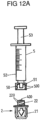
- a first connecting piece 11 is designed, together with an attachment part 2, to connect a conveying device 5 in the form of a syringe (see Fig. 12A and 12B ) in order to convey a liquid component into the container 1 via the connecting piece 11.
- the second connecting piece 12, however, together with an attachment part 3, provides an access via which, for example, an infusion set can be connected to the container 1 in order to supply a liquid from the container 1 to a patient.
- Fig. 2 shows an exploded view of the connection assemblies which are formed by the connection pieces 11, 12, the attachment parts 2, 3 and the sealing elements 4, 6 to be arranged between the connection pieces 11, 12 and the attachment parts 2, 3.
- the connection pieces 11, 12 are to be placed between films to produce the container 1 and are welded to the films so that the connection pieces 11, 12 are firmly bonded to the films.
- the attachment parts 2, 3 are to be attached to the connection pieces 11, 12 to complete the container 1 so that the sealing elements 4, 6 come to lie between the attachment parts 2, 3 and the connection pieces 11, 12 and in this way a transition between the attachment parts 2, 3 and the connection pieces 11, 12 is sealed liquid-tight.
- Each attachment part 2, 3 has a break-off piece 20, 30 that can be broken off to create access to the container 1.
- the break-off piece 20 can be broken off from the attachment part 2 in order to connect a conveying device 5 in the form of a syringe to the attachment part 2 and to convey liquid into the container 1 via it.
- the break-off piece 30 can be broken off from the attachment part 3 in order, for example, to pierce an infusion set with a piercing spike through the sealing element 6 and to remove liquid from the container 1 via it in order to supply the liquid to a patient, for example.
- Each attachment part 2, 3 also has a connecting section 21, 31 which can be brought into engagement with the associated connecting piece 11, 12 in order to connect the respective attachment piece 2, 3 in a form-fitting manner with the associated connecting piece 2, 3.
- the connector provided via the first connecting piece 11 and the attachment part 2 to be attached to it will be explained in detail below.
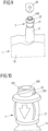
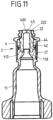
- FIG. 3 to 11 An embodiment of a connector comprising a connecting piece 11 and an attachment part 2 is shown Fig. 3 to 11 .
- the connecting piece 11 is to be connected to the film of the container 1 as described above and is thus held between the films in a material-locking manner.
- the attachment part 2 can be attached to the connecting piece 11 so that in the attached position the attachment part 2 is held in a form-fitting manner on the connecting piece 11.
- the attachment piece 2 has a first section, consisting of a connecting section 21 and an adjoining threaded section 22, and a break-off piece 20.
- the attachment piece 2 is formed in one piece as a plastic molded part and is present in an initial state with the break-off piece 20 connected to the threaded section 22.
- the connecting piece 11 has a flow opening 111 which, when the attachment part 2 is attached to the connecting piece 11, is closed off from the outside by the attachment part 2 so that no liquid can get out of the container 1 or into the container 1.
- the connecting piece 11 with a head 110 fits into an opening 210 of the connecting section 21 and is connected axially via a circumferential form-locking element in the form of an annular projection 115 and via form-locking elements 116, 117 in the form of axially extending webs and grooves to the attachment part 2 in a rotationally fixed manner.
- Complementary form-locking elements are formed within the opening 210 of the connecting section 21 of the attachment part 2, for example in the form of an annular recess for engagement with the circumferential form-locking element 115 and in the form of axially extending webs and/or grooves for engagement with the webs 116 and grooves 117.
- the sealing element 4 When the attachment part 2 is attached to the connecting piece 11, the sealing element 4 comes to lie between the attachment part 2 and the connecting piece 11 and is held in a clamped manner between the attachment part 2 and the connecting piece 11.
- the sealing element 4 can be inserted in an insertion direction E into the opening 210 within the attachment part 2 (see Fig. 6 ).
- the sealing element 4 is, as in Fig. 7 shown, is designed as a rotationally symmetrical body and has a sealing head 40 which comes to rest in an engagement opening 221 of the threaded section 22 and with a convexly curved or flat side 400 extends beyond the threaded section 22 in the direction of the break-off piece 20.
- the side 400 can also be substantially flush with the top of the threaded section 22.
- the sealing head 40 is adjoined by a cylindrical section 41 which merges into a shoulder 410 which, when the sealing element 4 is inserted into the opening 210, rests against a circumferential, conical contact surface 212 at the inner transition between the connecting section 21 and the threaded section 22 of the attachment part 2.
- the cylindrical section 41 here has a larger diameter than the sealing head 40.
- the shoulder 410 which projects radially outward over the section 41 and runs around the sealing element 4, is adjoined by a cylindrical body 42 which lies with play in the opening 210 of the connecting section 21.
- the cylindrical body 42 has a smaller diameter here than the shoulder 410. Because this body 42 lies in the opening 210 at a radial distance from the peripheral wall of the connecting section 21, the sealing element 4 can be deformed in a favorable manner when a conveying device 5 is attached in order to create a flow through the sealing element 4 between the conveying device 5 and the container 1.
- the body 42 has a circumferential flange 420.
- the flange 420 rests with its underside 422 on a support surface 114 of the connecting piece 11. Its upper side 421 can be completely exposed. In this case, the upper side 421 is not covered. It is not in contact with or in engagement with a corresponding component. For example, the upper side 421 is not covered by a clamping surface of the connecting piece 2.
- the upper side 421 of the flange 420 can also be exposed only in sections.
- the flange 420 can come to rest in sections between an annular projection 211 of the connecting section 21 and a support surface 114 on the head 110 of the connecting piece 11 when the attachment part 2 is attached to the connecting piece 11 and can thus be held in a clamped manner in sections between the annular projection 211 and the support surface 114.
- a radially outer section of the flange 420 is held in a clamped manner.
- the cylindrical body 42 has a recess 423 in its outer side. This can assist the deformation of the sealing element 4 when attaching a conveyor device 5.
- the recess 423 is provided by a step in the outer side. In cross section, the recess 423 has a substantially straight Bottom.
- the recess 423 has a cuboid-like cross-section. The bottom and the radial opening of the recess 423 can have essentially the same dimensions (seen in the insertion direction E).
- the flange 420 is connected to a foot section 43 which engages in a recess 113 on the head 110 of the connecting piece 11.
- the attachment part 2 rests on the front side against an outer flange 112 of the connecting piece 11.
- the sealing element 4 is supported with the shoulder 410 on the one hand on the attachment part 2 and via its flange 420 and the foot section 113 on the other hand on the connecting piece 11, a defined, secured position of the sealing element 4 within the opening 210 of the attachment part 2 is ensured.
- a cylindrical, inner opening 44 which extends through the body 42 and the cylindrical section 41 of the sealing element 4 starting from the foot section 43 up to the sealing head 40 and is in flow connection with a tapered flow section 118 of the connecting piece 111, a high flow rate between the conveying device 5 and the container 1 can be achieved when the conveying device 5 is attached to the attachment part 2.
- the inner opening 44 preferably has a diameter in a range from 1 mm to 5 mm, preferably from 2 mm to 4 mm.
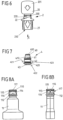
- the attachment part 2 is attached to the connecting piece 11 together with the sealing element 4, so that the connecting piece 11 is closed off from the outside.
- the sealing element 4 is not accessible from the outside because the upper side 400 of the sealing head 40 in the opening 221 of the threaded section 22 is covered from the outside by the break-off piece 20.
- the break-off piece 20 is connected to the threaded section 22 via a predetermined breaking point 200 in the form of a notch-like, circumferential recess.
- a conveying device 5 for example in the form of a syringe
- a user can break the break-off piece 20 from the threaded section 22 by grasping a grip element 201 of the break-off piece 20 with his fingers and detaching the break-off piece 20 from the threaded section 22, as shown in Fig. 9
- the attachment part 2 is thus without the break-off piece 20, as shown in Fig. 10 is shown.
- the sealing element 4 After breaking off the break-off piece 20, the sealing element 4 is exposed with its outward-facing, for example convex or flat, side 400 on the sealing head 40, so that this outward-facing side 400 can be accessed from the outside.
- the sealing element 4 can be conveniently wiped or dabbed on this side 400 in order to clean and disinfect the sealing element 4 - in accordance with any legal requirements that may exist.
- a flat side 400 can also be wiped or dabbed accordingly.
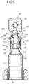
- a conveyor device 5 in the form of a syringe can be attached to the threaded section 22 by screwing a connecting element 50 in the form of a nut or union nut of the conveyor device 5 into engagement with threads 220 on the threaded section 22 via threads 500.
- a connecting piece 51 of the conveyor device 5 is inserted into the engagement opening 221 on the threaded section 22, so that the connecting piece 51 presses on the sealing head 40 of the sealing element 4, initially pressing it downwards and then at the slot opening 45 (see Fig. 11 ) opens.
- the connecting piece 51 thus penetrates the sealing head 40 at the slot opening 45 and comes into flow connection with the cylindrical opening 44, so that a flow is provided between the conveying device 5 and the flow opening 111 of the connecting piece 11.
- the sealing head 40 When the connecting piece 51 is pressed into the engagement opening 221, the sealing head 40 is also pressed into the attachment part 2 and, together with the other sections 41, 42, is pushed aside into the space available radially outside the section 42.
- the connecting piece 51 When the connecting piece 51 is fully inserted, the connecting piece 51 engages in a form-fitting manner in the engagement opening 221 and passes through the sealing head 40, whereby a favorable flow connection is created between the connecting piece 51 and the flow opening 118 on the head 110 of the connecting piece 11, which is not or only insignificantly impaired by the sealing element 4.
- the conveyor device 5 extends at the latest in the fully attached, here for example screwed, state with its connecting piece 51 through the slot opening 45 of the sealing element 4, so that a flow between the conveyor device 5 and the container 1 can take place unhindered or essentially unhindered through the sealing element 4.
- the entire opening cross-section in the conveyor device 5, through which the liquid transport takes place, is released.
- the conveying device 5 has a syringe body 52 and a plunger 53 which can be pushed into the syringe body 52 in order to convey a liquid from the syringe body 52 into the container 1.
- a slotted opening 45 for example a cross-shaped or straight one, is provided in the sealing head 40 of the sealing element 4, a needle-free access is created which can be accessed using a conveyor device 5 without an injection needle.
- the connecting piece 51 engages with the slotted opening 45 and in this way opens the sealing element 4, so that a flow is created between the conveyor device 5 and the container 1.
- the sealing element 4 closes automatically and in a self-sealing manner so that no liquid can escape from the container 1.
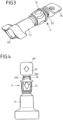
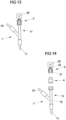
- Fig. 13 and 14 show a further embodiment in which a connection assembly consisting of a connection piece 11, an attachment part 2 arranged thereon and a sealing element 4 is used.
- connection assembly is part of a connector 7 in the form of a so-called Y-connector.
- the connector 7 has two line connections 70, 71, to each of which a medical line in the form of an infusion tube or the like can be connected.
- the line connections 70, 71 are in flow connection with the connection piece 11 at a connection point 72, so that a medical liquid can be introduced into a line system that is connected to the line connections 70, 71 or removed from the line system via the connection piece 11.
- an attachment part 2 is arranged on the connecting piece 11.
- a sealing element 4 is clamped between the attachment part 2 and the connecting piece 11.
- a break-off piece 20 is connected to the threaded section 22 of the attachment part 2, which can be broken off to form a conveyor device 5 (see Fig. 12 ) with the threaded section 22 and to connect the conveyor device 5 to the Connecting piece 11.
- the sealing element 4 can protrude outwards with a convex side 400 over the top 222 of the threaded section 22 and is thus easily accessible from the outside, the sealing element 4 can be conveniently wiped on its side 400 before connecting the conveyor device 5 in order to disinfect the sealing element 4 on its outward-facing side 400.
- a flat side 400 can also be wiped or dabbed accordingly.
- Both the connecting piece 11 and the attachment part 2 are identical in their design and function as described above for the embodiment according to Fig. 1 to 12B , so reference should be made to the preceding statements.
Landscapes
- Health & Medical Sciences (AREA)
- Pharmacology & Pharmacy (AREA)
- Life Sciences & Earth Sciences (AREA)
- Animal Behavior & Ethology (AREA)
- General Health & Medical Sciences (AREA)
- Public Health (AREA)
- Veterinary Medicine (AREA)
- Physics & Mathematics (AREA)
- Fluid Mechanics (AREA)
- Hematology (AREA)
- Infusion, Injection, And Reservoir Apparatuses (AREA)
- Medical Preparation Storing Or Oral Administration Devices (AREA)
- Quick-Acting Or Multi-Walled Pipe Joints (AREA)
Priority Applications (1)
| Application Number | Priority Date | Filing Date | Title |
|---|---|---|---|
| EP24223801.2A EP4509114A3 (de) | 2015-05-22 | 2016-05-23 | Anschlussbaugruppe zum leiten einer medizinischen flüssigkeit |
Applications Claiming Priority (2)
| Application Number | Priority Date | Filing Date | Title |
|---|---|---|---|
| EP15168952 | 2015-05-22 | ||
| PCT/EP2016/061582 WO2016188957A1 (de) | 2015-05-22 | 2016-05-23 | Anschlussbaugruppe zum leiten einer medizinischen flüssigkeit |
Related Child Applications (1)
| Application Number | Title | Priority Date | Filing Date |
|---|---|---|---|
| EP24223801.2A Division EP4509114A3 (de) | 2015-05-22 | 2016-05-23 | Anschlussbaugruppe zum leiten einer medizinischen flüssigkeit |
Publications (3)
| Publication Number | Publication Date |
|---|---|
| EP3297596A1 EP3297596A1 (de) | 2018-03-28 |
| EP3297596B1 true EP3297596B1 (de) | 2025-01-01 |
| EP3297596C0 EP3297596C0 (de) | 2025-01-01 |
Family
ID=53274412
Family Applications (2)
| Application Number | Title | Priority Date | Filing Date |
|---|---|---|---|
| EP16727339.0A Active EP3297596B1 (de) | 2015-05-22 | 2016-05-23 | Anschlussbaugruppe zum leiten einer medizinischen flüssigkeit |
| EP24223801.2A Pending EP4509114A3 (de) | 2015-05-22 | 2016-05-23 | Anschlussbaugruppe zum leiten einer medizinischen flüssigkeit |
Family Applications After (1)
| Application Number | Title | Priority Date | Filing Date |
|---|---|---|---|
| EP24223801.2A Pending EP4509114A3 (de) | 2015-05-22 | 2016-05-23 | Anschlussbaugruppe zum leiten einer medizinischen flüssigkeit |
Country Status (14)
| Country | Link |
|---|---|
| US (3) | US11234898B2 (enExample) |
| EP (2) | EP3297596B1 (enExample) |
| JP (3) | JP2018515266A (enExample) |
| KR (1) | KR102593070B1 (enExample) |
| CN (1) | CN107645948B (enExample) |
| AU (1) | AU2016266694B2 (enExample) |
| BR (1) | BR112017022203B1 (enExample) |
| CA (1) | CA2986496C (enExample) |
| CL (1) | CL2017002968A1 (enExample) |
| ES (1) | ES3033814T3 (enExample) |
| MX (1) | MX392652B (enExample) |
| PL (1) | PL3297596T3 (enExample) |
| WO (1) | WO2016188957A1 (enExample) |
| ZA (1) | ZA201707390B (enExample) |
Families Citing this family (6)
| Publication number | Priority date | Publication date | Assignee | Title |
|---|---|---|---|---|
| KR102593070B1 (ko) | 2015-05-22 | 2023-10-23 | 프레제니우스 카비 도이치란트 게엠베하 | 의료용 액체를 안내하기 위한 연결 조립체 |
| US11883364B2 (en) | 2015-05-22 | 2024-01-30 | Fresenius Kabi Deutschland Gmbh | Connection assembly for directing a medical liquid |
| EP3810254B1 (en) * | 2018-06-20 | 2024-02-21 | Fresenius Kabi Deutschland GmbH | Connector assembly for connecting medical lines comprising a cap element |
| EP3934604A1 (en) * | 2019-03-08 | 2022-01-12 | Fresenius Kabi Deutschland GmbH | Connection assembly for directing a medical liquid |
| WO2021122268A1 (de) | 2019-12-17 | 2021-06-24 | Fresenius Kabi Deutschland Gmbh | Konnektor und anschlusssystem für eine medizinische verpackung sowie verfahren zum bereitstellen einer flüssigkeit für eine medizinische verpackung |
| USD983407S1 (en) * | 2020-10-20 | 2023-04-11 | Verrica Pharmaceuticals Inc. | Ampule crush tool |
Citations (2)
| Publication number | Priority date | Publication date | Assignee | Title |
|---|---|---|---|---|
| WO1998026835A1 (en) * | 1996-12-16 | 1998-06-25 | Icu Medical, Inc. | Positive flow valve |
| WO2006103792A1 (ja) * | 2005-03-28 | 2006-10-05 | Kabushiki Kaisha Top | コネクタ |
Family Cites Families (21)
| Publication number | Priority date | Publication date | Assignee | Title |
|---|---|---|---|---|
| CZ149294A3 (en) | 1991-12-18 | 1994-11-16 | Icu Medical Inc | Medicinal valve |
| DE19546580C1 (de) * | 1995-12-13 | 1996-12-12 | Fresenius Ag | Zugangsstück zur weitgehend luftfreien Flüssigkeitszuleitung und/oder Flüssigkeitsentnahme |
| JP3935292B2 (ja) | 1999-09-16 | 2007-06-20 | テルモ株式会社 | コネクタ |
| US6651956B2 (en) | 2002-01-31 | 2003-11-25 | Halkey-Roberts Corporation | Slit-type swabable valve |
| CA2512775C (en) * | 2003-01-09 | 2011-03-22 | Fukai Kogyo Kabushiki Kaisha | Seal valve, connection port, mix-feed tube, connection device for liquid infusion, circuit and connection system for liquid infusion circuit that are for medical device |
| DE10313760B3 (de) | 2003-03-27 | 2004-06-03 | Fresenius Kabi Deutschland Gmbh | Konnektor für medizinische Flüssigkeiten enthaltende Verpackungen und Verpackung für medizinische Flüssigkeiten |
| DE10348016B4 (de) * | 2003-10-15 | 2007-05-03 | Fresenius Kabi Deutschland Gmbh | Konnektor für medizinische Flüssigkeiten enthaltende Verpackungen und Verpackung für medizinische Flüssigkeiten |
| ITTO20040524A1 (it) * | 2004-07-27 | 2004-10-27 | Borla Ind | Connettore valvolareper linee medicali di infusione |
| WO2006096960A1 (en) | 2005-03-15 | 2006-09-21 | Vasogen Ireland Limited | Controlled flow adapter for medical fluid containers |
| DE102007005407A1 (de) | 2007-02-03 | 2008-08-07 | Fresenius Kabi Deutschland Gmbh | Verschlusskappe für ein Behältnis zur Aufnahme von medizinischen Flüssigkeiten und Behältnis zur Aufnahme von medizinischen Flüssigkeiten |
| DE102008048988A1 (de) | 2008-09-25 | 2010-04-08 | Fresenius Kabi Deutschland Gmbh | Vorrichtung zum Anschluss einer Spritze an ein Behältnis oder eine Schlauchleitung |
| DE102008060864A1 (de) | 2008-12-09 | 2010-06-10 | Fresenius Kabi Deutschland Gmbh | Verschlusskappe für Behältnisse zur Aufnahme von medizinischen Flüssigkeiten und Behältnis zur Aufnahme von medizinischen Flüssigkeiten |
| US7967797B2 (en) * | 2009-05-19 | 2011-06-28 | Nexus Medical, Llc | Intravascular valve component with improved valve positioning |
| WO2010151507A1 (en) | 2009-06-22 | 2010-12-29 | Np Medical Inc. | Medical valve with improved back-pressure sealing |
| US8758306B2 (en) | 2010-05-17 | 2014-06-24 | Icu Medical, Inc. | Medical connectors and methods of use |
| ES2577852T3 (es) | 2010-10-12 | 2016-07-19 | Codan Holding Gmbh | Conjunto de válvula médica |
| EP2444117A1 (de) * | 2010-10-20 | 2012-04-25 | Fresenius Kabi Deutschland GmbH | Schutzkappe für einen Konnektor |
| ES2748502T3 (es) * | 2013-03-16 | 2020-03-17 | Poly Medicure Ltd | Válvula de dispositivo de transferencia |
| JP2017513613A (ja) * | 2014-04-21 | 2017-06-01 | ベクトン ディキンソン アンド カンパニー リミテッド | 流体の閉じた移送のためのシステム |
| KR102593070B1 (ko) | 2015-05-22 | 2023-10-23 | 프레제니우스 카비 도이치란트 게엠베하 | 의료용 액체를 안내하기 위한 연결 조립체 |
| DE102016012059A1 (de) | 2016-10-08 | 2018-04-12 | Fresenius Kabi Deutschland Gmbh | Konnektor für ein eine Flüssigkeit enthaltendes medizinisches Packmittel |
-
2016
- 2016-05-23 KR KR1020177033305A patent/KR102593070B1/ko active Active
- 2016-05-23 AU AU2016266694A patent/AU2016266694B2/en active Active
- 2016-05-23 CA CA2986496A patent/CA2986496C/en active Active
- 2016-05-23 CN CN201680029628.1A patent/CN107645948B/zh active Active
- 2016-05-23 EP EP16727339.0A patent/EP3297596B1/de active Active
- 2016-05-23 EP EP24223801.2A patent/EP4509114A3/de active Pending
- 2016-05-23 ES ES16727339T patent/ES3033814T3/es active Active
- 2016-05-23 MX MX2017014876A patent/MX392652B/es unknown
- 2016-05-23 PL PL16727339.0T patent/PL3297596T3/pl unknown
- 2016-05-23 WO PCT/EP2016/061582 patent/WO2016188957A1/de not_active Ceased
- 2016-05-23 BR BR112017022203-5A patent/BR112017022203B1/pt active IP Right Grant
- 2016-05-23 US US15/576,438 patent/US11234898B2/en active Active
- 2016-05-23 JP JP2017560550A patent/JP2018515266A/ja active Pending
-
2017
- 2017-10-31 ZA ZA2017/07390A patent/ZA201707390B/en unknown
- 2017-11-22 CL CL2017002968A patent/CL2017002968A1/es unknown
- 2017-11-22 US US15/821,724 patent/US10576019B2/en active Active
-
2018
- 2018-05-30 US US15/992,568 patent/US11291608B2/en active Active
-
2021
- 2021-01-28 JP JP2021012200A patent/JP7504037B2/ja active Active
-
2023
- 2023-08-16 JP JP2023132546A patent/JP2023156446A/ja not_active Withdrawn
Patent Citations (2)
| Publication number | Priority date | Publication date | Assignee | Title |
|---|---|---|---|---|
| WO1998026835A1 (en) * | 1996-12-16 | 1998-06-25 | Icu Medical, Inc. | Positive flow valve |
| WO2006103792A1 (ja) * | 2005-03-28 | 2006-10-05 | Kabushiki Kaisha Top | コネクタ |
Also Published As
| Publication number | Publication date |
|---|---|
| CA2986496A1 (en) | 2016-12-01 |
| ES3033814T3 (en) | 2025-08-08 |
| EP4509114A3 (de) | 2025-10-01 |
| BR112017022203A2 (pt) | 2018-07-03 |
| AU2016266694B2 (en) | 2020-07-09 |
| CN107645948A (zh) | 2018-01-30 |
| PL3297596T3 (pl) | 2025-03-03 |
| US11291608B2 (en) | 2022-04-05 |
| US20180153770A1 (en) | 2018-06-07 |
| AU2016266694A1 (en) | 2017-11-02 |
| ZA201707390B (en) | 2019-01-30 |
| BR112017022203B1 (pt) | 2022-04-05 |
| CA2986496C (en) | 2024-06-11 |
| CN107645948B (zh) | 2021-10-29 |
| MX2017014876A (es) | 2018-04-20 |
| KR102593070B1 (ko) | 2023-10-23 |
| EP3297596A1 (de) | 2018-03-28 |
| US20180271748A1 (en) | 2018-09-27 |
| CL2017002968A1 (es) | 2018-06-08 |
| WO2016188957A1 (de) | 2016-12-01 |
| EP4509114A2 (de) | 2025-02-19 |
| JP2021072934A (ja) | 2021-05-13 |
| JP2023156446A (ja) | 2023-10-24 |
| US10576019B2 (en) | 2020-03-03 |
| US11234898B2 (en) | 2022-02-01 |
| MX392652B (es) | 2025-03-21 |
| EP3297596C0 (de) | 2025-01-01 |
| JP2018515266A (ja) | 2018-06-14 |
| JP7504037B2 (ja) | 2024-06-21 |
| US20180092807A1 (en) | 2018-04-05 |
| KR20180011098A (ko) | 2018-01-31 |
| HK1247551A1 (zh) | 2018-09-28 |
Similar Documents
| Publication | Publication Date | Title |
|---|---|---|
| EP3297596B1 (de) | Anschlussbaugruppe zum leiten einer medizinischen flüssigkeit | |
| EP1673135B1 (de) | Konnektor für medizinische flüssigkeiten enthaltende verpackungen und verpackung für medizinische flüssigkeiten | |
| EP2114345B1 (de) | Verschlusskappe für ein behältnis zur aufnahme von medizinischen flüssigkeiten und behältnis zur aufnahme von medizinischen flüssigkeiten | |
| EP3044104B1 (de) | Ampulle für eine medizinische flüssigkeit und verfahren zum herstellen einer ampulle | |
| WO2010034470A1 (de) | Konnektor mit membran zum anschluss einer spritze an ein behältnis oder eine schlauchleitung | |
| DE69623268T2 (de) | Vorgefüllte spritze zur verabreichung von medikamenten | |
| DE69723278T2 (de) | Pharmazeutische ampulle | |
| EP2667838A1 (de) | Verbindungsvorrichtung zum verbinden eines ersten reservoirs mit einem zweiten reservoir | |
| CH691031A5 (de) | Zweiteilige Vorrichtung für die Verabreichung von Arzneimitteln. | |
| EP0788804A2 (de) | Applikationsvorrichting für medizinische Flüssigkeiten | |
| EP2536377A1 (de) | Verschlusskappe für ein behältnis zur aufnahme von medizinischen flüssigkeiten und behältnis | |
| EP4171718A1 (de) | System umfassend eine kappe für medizinischen fluidbehälter und ein ansatzteil, medizinischer fluidbehälter, verfahren zum herstellen eines fluidbehälters | |
| EP3522973B1 (de) | Konnektor für ein eine flüssigkeit enthaltendes medizinisches packmittel | |
| EP3294256B1 (de) | Behältnis für eine medizinische flüssigkeit | |
| EP3002021B1 (de) | Stopfen zum aufsetzen auf ein anschlusselement einer medizinischen spritze | |
| EP3174812A1 (de) | Behälter mit kopfstück, der mit einem medium befüllbar oder befüllt ist | |
| EP2756854B1 (de) | Medizinischer Fluidbeutel | |
| EP1721595B1 (de) | Behälter für die Bereitstellung medizinischer Flüssigkeiten | |
| DE102019101279B4 (de) | Vorfüllbare Spritze | |
| WO2025036776A1 (de) | Medizinische montageeinrichtung für ein cstd-system | |
| AT516438A1 (de) | Handhabungsvorrichtung sowie Verfahren zu deren Herstellung | |
| DE29612534U1 (de) | Infusionsset | |
| WO2007062775A1 (de) | Vorrichtung zum überleiten von flüssigkeiten, suspensionen und/oder feststoffen von einem ersten gefäss in ein zweites gefäss |
Legal Events
| Date | Code | Title | Description |
|---|---|---|---|
| STAA | Information on the status of an ep patent application or granted ep patent |
Free format text: STATUS: THE INTERNATIONAL PUBLICATION HAS BEEN MADE |
|
| PUAI | Public reference made under article 153(3) epc to a published international application that has entered the european phase |
Free format text: ORIGINAL CODE: 0009012 |
|
| STAA | Information on the status of an ep patent application or granted ep patent |
Free format text: STATUS: REQUEST FOR EXAMINATION WAS MADE |
|
| 17P | Request for examination filed |
Effective date: 20171128 |
|
| AK | Designated contracting states |
Kind code of ref document: A1 Designated state(s): AL AT BE BG CH CY CZ DE DK EE ES FI FR GB GR HR HU IE IS IT LI LT LU LV MC MK MT NL NO PL PT RO RS SE SI SK SM TR |
|
| AX | Request for extension of the european patent |
Extension state: BA ME |
|
| DAV | Request for validation of the european patent (deleted) | ||
| DAX | Request for extension of the european patent (deleted) | ||
| REG | Reference to a national code |
Ref country code: HK Ref legal event code: DE Ref document number: 1247551 Country of ref document: HK |
|
| STAA | Information on the status of an ep patent application or granted ep patent |
Free format text: STATUS: EXAMINATION IS IN PROGRESS |
|
| 17Q | First examination report despatched |
Effective date: 20200729 |
|
| REG | Reference to a national code |
Ref legal event code: R079 Free format text: PREVIOUS MAIN CLASS: A61J0001140000 Ipc: A61J0001200000 Ref country code: DE Ref legal event code: R079 Ref document number: 502016016853 Country of ref document: DE Free format text: PREVIOUS MAIN CLASS: A61J0001140000 Ipc: A61J0001200000 |
|
| GRAP | Despatch of communication of intention to grant a patent |
Free format text: ORIGINAL CODE: EPIDOSNIGR1 |
|
| STAA | Information on the status of an ep patent application or granted ep patent |
Free format text: STATUS: GRANT OF PATENT IS INTENDED |
|
| RIC1 | Information provided on ipc code assigned before grant |
Ipc: A61J 1/20 20060101AFI20240712BHEP Ipc: A61J 1/14 20060101ALI20240712BHEP Ipc: A61J 1/10 20060101ALI20240712BHEP |
|
| INTG | Intention to grant announced |
Effective date: 20240724 |
|
| GRAS | Grant fee paid |
Free format text: ORIGINAL CODE: EPIDOSNIGR3 |
|
| GRAA | (expected) grant |
Free format text: ORIGINAL CODE: 0009210 |
|
| STAA | Information on the status of an ep patent application or granted ep patent |
Free format text: STATUS: THE PATENT HAS BEEN GRANTED |
|
| AK | Designated contracting states |
Kind code of ref document: B1 Designated state(s): AL AT BE BG CH CY CZ DE DK EE ES FI FR GB GR HR HU IE IS IT LI LT LU LV MC MK MT NL NO PL PT RO RS SE SI SK SM TR |
|
| REG | Reference to a national code |
Ref country code: GB Ref legal event code: FG4D Free format text: NOT ENGLISH |
|
| REG | Reference to a national code |
Ref country code: DE Ref legal event code: R096 Ref document number: 502016016853 Country of ref document: DE |
|
| REG | Reference to a national code |
Ref country code: CH Ref legal event code: EP |
|
| REG | Reference to a national code |
Ref country code: IE Ref legal event code: FG4D Free format text: LANGUAGE OF EP DOCUMENT: GERMAN |
|
| U01 | Request for unitary effect filed |
Effective date: 20250123 |
|
| U07 | Unitary effect registered |
Designated state(s): AT BE BG DE DK EE FI FR IT LT LU LV MT NL PT RO SE SI Effective date: 20250129 |
|
| U20 | Renewal fee for the european patent with unitary effect paid |
Year of fee payment: 10 Effective date: 20250526 |
|
| PGFP | Annual fee paid to national office [announced via postgrant information from national office to epo] |
Ref country code: PL Payment date: 20250401 Year of fee payment: 10 |
|
| PGFP | Annual fee paid to national office [announced via postgrant information from national office to epo] |
Ref country code: ES Payment date: 20250606 Year of fee payment: 10 Ref country code: GB Payment date: 20250526 Year of fee payment: 10 |
|
| PG25 | Lapsed in a contracting state [announced via postgrant information from national office to epo] |
Ref country code: IS Free format text: LAPSE BECAUSE OF FAILURE TO SUBMIT A TRANSLATION OF THE DESCRIPTION OR TO PAY THE FEE WITHIN THE PRESCRIBED TIME-LIMIT Effective date: 20250501 |
|
| PGFP | Annual fee paid to national office [announced via postgrant information from national office to epo] |
Ref country code: NO Payment date: 20250527 Year of fee payment: 10 |
|
| PG25 | Lapsed in a contracting state [announced via postgrant information from national office to epo] |
Ref country code: HR Free format text: LAPSE BECAUSE OF FAILURE TO SUBMIT A TRANSLATION OF THE DESCRIPTION OR TO PAY THE FEE WITHIN THE PRESCRIBED TIME-LIMIT Effective date: 20250101 |
|
| PG25 | Lapsed in a contracting state [announced via postgrant information from national office to epo] |
Ref country code: GR Free format text: LAPSE BECAUSE OF FAILURE TO SUBMIT A TRANSLATION OF THE DESCRIPTION OR TO PAY THE FEE WITHIN THE PRESCRIBED TIME-LIMIT Effective date: 20250402 |
|
| PGFP | Annual fee paid to national office [announced via postgrant information from national office to epo] |
Ref country code: CH Payment date: 20250612 Year of fee payment: 10 |
|
| PG25 | Lapsed in a contracting state [announced via postgrant information from national office to epo] |
Ref country code: CZ Free format text: LAPSE BECAUSE OF FAILURE TO SUBMIT A TRANSLATION OF THE DESCRIPTION OR TO PAY THE FEE WITHIN THE PRESCRIBED TIME-LIMIT Effective date: 20250101 |
|
| REG | Reference to a national code |
Ref country code: ES Ref legal event code: FG2A Ref document number: 3033814 Country of ref document: ES Kind code of ref document: T3 Effective date: 20250808 |
|
| PG25 | Lapsed in a contracting state [announced via postgrant information from national office to epo] |
Ref country code: SM Free format text: LAPSE BECAUSE OF FAILURE TO SUBMIT A TRANSLATION OF THE DESCRIPTION OR TO PAY THE FEE WITHIN THE PRESCRIBED TIME-LIMIT Effective date: 20250101 |
|
| PG25 | Lapsed in a contracting state [announced via postgrant information from national office to epo] |
Ref country code: SK Free format text: LAPSE BECAUSE OF FAILURE TO SUBMIT A TRANSLATION OF THE DESCRIPTION OR TO PAY THE FEE WITHIN THE PRESCRIBED TIME-LIMIT Effective date: 20250101 |
|
| PLBE | No opposition filed within time limit |
Free format text: ORIGINAL CODE: 0009261 |
|
| STAA | Information on the status of an ep patent application or granted ep patent |
Free format text: STATUS: NO OPPOSITION FILED WITHIN TIME LIMIT |
|
| 26N | No opposition filed |
Effective date: 20251002 |