EP3293282A1 - Techniques for depositing transparent conductive oxide coatings using dual c-mag sputter apparatuses - Google Patents
Techniques for depositing transparent conductive oxide coatings using dual c-mag sputter apparatuses Download PDFInfo
- Publication number
- EP3293282A1 EP3293282A1 EP17198035.2A EP17198035A EP3293282A1 EP 3293282 A1 EP3293282 A1 EP 3293282A1 EP 17198035 A EP17198035 A EP 17198035A EP 3293282 A1 EP3293282 A1 EP 3293282A1
- Authority
- EP
- European Patent Office
- Prior art keywords
- oxygen
- flow
- gas
- target
- example embodiments
- Prior art date
- Legal status (The legal status is an assumption and is not a legal conclusion. Google has not performed a legal analysis and makes no representation as to the accuracy of the status listed.)
- Withdrawn
Links
- 238000000034 method Methods 0.000 title claims abstract description 82
- 238000000576 coating method Methods 0.000 title claims abstract description 36
- 238000000151 deposition Methods 0.000 title claims abstract description 24
- 230000009977 dual effect Effects 0.000 title claims abstract description 14
- QVGXLLKOCUKJST-UHFFFAOYSA-N atomic oxygen Chemical compound [O] QVGXLLKOCUKJST-UHFFFAOYSA-N 0.000 claims abstract description 79
- 239000007789 gas Substances 0.000 claims abstract description 79
- 239000001301 oxygen Substances 0.000 claims abstract description 79
- 229910052760 oxygen Inorganic materials 0.000 claims abstract description 79
- 238000004544 sputter deposition Methods 0.000 claims abstract description 48
- 230000036961 partial effect Effects 0.000 claims abstract description 19
- MYMOFIZGZYHOMD-UHFFFAOYSA-N Dioxygen Chemical compound O=O MYMOFIZGZYHOMD-UHFFFAOYSA-N 0.000 claims abstract description 14
- 229910001882 dioxygen Inorganic materials 0.000 claims abstract description 14
- 239000011248 coating agent Substances 0.000 claims description 25
- 238000009826 distribution Methods 0.000 claims description 21
- XKRFYHLGVUSROY-UHFFFAOYSA-N Argon Chemical compound [Ar] XKRFYHLGVUSROY-UHFFFAOYSA-N 0.000 claims description 14
- 229910052786 argon Inorganic materials 0.000 claims description 7
- 238000004519 manufacturing process Methods 0.000 claims description 7
- 230000008569 process Effects 0.000 abstract description 43
- 239000011261 inert gas Substances 0.000 abstract description 15
- 230000010355 oscillation Effects 0.000 abstract description 8
- 230000002829 reductive effect Effects 0.000 abstract description 7
- 239000010408 film Substances 0.000 description 37
- 238000010521 absorption reaction Methods 0.000 description 30
- 239000000758 substrate Substances 0.000 description 17
- 239000010410 layer Substances 0.000 description 14
- 230000008021 deposition Effects 0.000 description 11
- 230000007704 transition Effects 0.000 description 11
- 239000000463 material Substances 0.000 description 10
- 230000003628 erosive effect Effects 0.000 description 9
- 239000011521 glass Substances 0.000 description 9
- 239000000203 mixture Substances 0.000 description 9
- 238000007254 oxidation reaction Methods 0.000 description 9
- XLOMVQKBTHCTTD-UHFFFAOYSA-N Zinc monoxide Chemical compound [Zn]=O XLOMVQKBTHCTTD-UHFFFAOYSA-N 0.000 description 8
- 230000008859 change Effects 0.000 description 8
- 230000003647 oxidation Effects 0.000 description 8
- 230000006872 improvement Effects 0.000 description 7
- 229910052751 metal Inorganic materials 0.000 description 7
- 239000002184 metal Substances 0.000 description 7
- 238000001755 magnetron sputter deposition Methods 0.000 description 6
- 238000005457 optimization Methods 0.000 description 6
- 239000002356 single layer Substances 0.000 description 6
- 238000013459 approach Methods 0.000 description 5
- 230000004048 modification Effects 0.000 description 5
- 239000013077 target material Substances 0.000 description 5
- 239000010409 thin film Substances 0.000 description 5
- XOLBLPGZBRYERU-UHFFFAOYSA-N tin dioxide Chemical compound O=[Sn]=O XOLBLPGZBRYERU-UHFFFAOYSA-N 0.000 description 5
- 238000012986 modification Methods 0.000 description 4
- 239000002245 particle Substances 0.000 description 4
- 238000010301 surface-oxidation reaction Methods 0.000 description 4
- 238000012360 testing method Methods 0.000 description 4
- 239000011787 zinc oxide Substances 0.000 description 4
- 229910001128 Sn alloy Inorganic materials 0.000 description 3
- 239000000919 ceramic Substances 0.000 description 3
- 230000000875 corresponding effect Effects 0.000 description 3
- 230000003247 decreasing effect Effects 0.000 description 3
- APFVFJFRJDLVQX-UHFFFAOYSA-N indium atom Chemical compound [In] APFVFJFRJDLVQX-UHFFFAOYSA-N 0.000 description 3
- 230000004044 response Effects 0.000 description 3
- XLYOFNOQVPJJNP-UHFFFAOYSA-N water Substances O XLYOFNOQVPJJNP-UHFFFAOYSA-N 0.000 description 3
- 229910000846 In alloy Inorganic materials 0.000 description 2
- 238000000429 assembly Methods 0.000 description 2
- 230000000712 assembly Effects 0.000 description 2
- 238000001816 cooling Methods 0.000 description 2
- 239000000498 cooling water Substances 0.000 description 2
- 238000012937 correction Methods 0.000 description 2
- 230000000737 periodic effect Effects 0.000 description 2
- 238000005546 reactive sputtering Methods 0.000 description 2
- 230000009467 reduction Effects 0.000 description 2
- 238000005477 sputtering target Methods 0.000 description 2
- 238000009827 uniform distribution Methods 0.000 description 2
- 238000012800 visualization Methods 0.000 description 2
- 229910000831 Steel Inorganic materials 0.000 description 1
- 230000001154 acute effect Effects 0.000 description 1
- 238000005275 alloying Methods 0.000 description 1
- 239000000969 carrier Substances 0.000 description 1
- 230000015556 catabolic process Effects 0.000 description 1
- 150000001875 compounds Chemical class 0.000 description 1
- 239000002826 coolant Substances 0.000 description 1
- 239000012809 cooling fluid Substances 0.000 description 1
- 230000002596 correlated effect Effects 0.000 description 1
- 238000005336 cracking Methods 0.000 description 1
- 230000006735 deficit Effects 0.000 description 1
- 238000006731 degradation reaction Methods 0.000 description 1
- 238000005137 deposition process Methods 0.000 description 1
- 230000000694 effects Effects 0.000 description 1
- 230000002349 favourable effect Effects 0.000 description 1
- -1 for example Substances 0.000 description 1
- 229910052738 indium Inorganic materials 0.000 description 1
- AMGQUBHHOARCQH-UHFFFAOYSA-N indium;oxotin Chemical compound [In].[Sn]=O AMGQUBHHOARCQH-UHFFFAOYSA-N 0.000 description 1
- 239000007788 liquid Substances 0.000 description 1
- 238000005259 measurement Methods 0.000 description 1
- 239000007769 metal material Substances 0.000 description 1
- 229910044991 metal oxide Inorganic materials 0.000 description 1
- 150000004706 metal oxides Chemical group 0.000 description 1
- 230000003287 optical effect Effects 0.000 description 1
- 238000004886 process control Methods 0.000 description 1
- 238000011165 process development Methods 0.000 description 1
- 238000005086 pumping Methods 0.000 description 1
- 230000002441 reversible effect Effects 0.000 description 1
- 230000035945 sensitivity Effects 0.000 description 1
- 230000003595 spectral effect Effects 0.000 description 1
- 229910001256 stainless steel alloy Inorganic materials 0.000 description 1
- 230000003068 static effect Effects 0.000 description 1
- 239000010959 steel Substances 0.000 description 1
- 239000000126 substance Substances 0.000 description 1
- 230000009897 systematic effect Effects 0.000 description 1
- 229910001887 tin oxide Inorganic materials 0.000 description 1
- 238000001429 visible spectrum Methods 0.000 description 1
Images








Classifications
-
- C—CHEMISTRY; METALLURGY
- C23—COATING METALLIC MATERIAL; COATING MATERIAL WITH METALLIC MATERIAL; CHEMICAL SURFACE TREATMENT; DIFFUSION TREATMENT OF METALLIC MATERIAL; COATING BY VACUUM EVAPORATION, BY SPUTTERING, BY ION IMPLANTATION OR BY CHEMICAL VAPOUR DEPOSITION, IN GENERAL; INHIBITING CORROSION OF METALLIC MATERIAL OR INCRUSTATION IN GENERAL
- C23C—COATING METALLIC MATERIAL; COATING MATERIAL WITH METALLIC MATERIAL; SURFACE TREATMENT OF METALLIC MATERIAL BY DIFFUSION INTO THE SURFACE, BY CHEMICAL CONVERSION OR SUBSTITUTION; COATING BY VACUUM EVAPORATION, BY SPUTTERING, BY ION IMPLANTATION OR BY CHEMICAL VAPOUR DEPOSITION, IN GENERAL
- C23C14/00—Coating by vacuum evaporation, by sputtering or by ion implantation of the coating forming material
- C23C14/0021—Reactive sputtering or evaporation
- C23C14/0036—Reactive sputtering
- C23C14/0042—Controlling partial pressure or flow rate of reactive or inert gases with feedback of measurements
-
- C—CHEMISTRY; METALLURGY
- C23—COATING METALLIC MATERIAL; COATING MATERIAL WITH METALLIC MATERIAL; CHEMICAL SURFACE TREATMENT; DIFFUSION TREATMENT OF METALLIC MATERIAL; COATING BY VACUUM EVAPORATION, BY SPUTTERING, BY ION IMPLANTATION OR BY CHEMICAL VAPOUR DEPOSITION, IN GENERAL; INHIBITING CORROSION OF METALLIC MATERIAL OR INCRUSTATION IN GENERAL
- C23C—COATING METALLIC MATERIAL; COATING MATERIAL WITH METALLIC MATERIAL; SURFACE TREATMENT OF METALLIC MATERIAL BY DIFFUSION INTO THE SURFACE, BY CHEMICAL CONVERSION OR SUBSTITUTION; COATING BY VACUUM EVAPORATION, BY SPUTTERING, BY ION IMPLANTATION OR BY CHEMICAL VAPOUR DEPOSITION, IN GENERAL
- C23C14/00—Coating by vacuum evaporation, by sputtering or by ion implantation of the coating forming material
- C23C14/22—Coating by vacuum evaporation, by sputtering or by ion implantation of the coating forming material characterised by the process of coating
- C23C14/34—Sputtering
- C23C14/35—Sputtering by application of a magnetic field, e.g. magnetron sputtering
- C23C14/352—Sputtering by application of a magnetic field, e.g. magnetron sputtering using more than one target
-
- H—ELECTRICITY
- H01—ELECTRIC ELEMENTS
- H01J—ELECTRIC DISCHARGE TUBES OR DISCHARGE LAMPS
- H01J37/00—Discharge tubes with provision for introducing objects or material to be exposed to the discharge, e.g. for the purpose of examination or processing thereof
- H01J37/32—Gas-filled discharge tubes
- H01J37/32431—Constructional details of the reactor
- H01J37/3244—Gas supply means
-
- H—ELECTRICITY
- H01—ELECTRIC ELEMENTS
- H01J—ELECTRIC DISCHARGE TUBES OR DISCHARGE LAMPS
- H01J37/00—Discharge tubes with provision for introducing objects or material to be exposed to the discharge, e.g. for the purpose of examination or processing thereof
- H01J37/32—Gas-filled discharge tubes
- H01J37/32431—Constructional details of the reactor
- H01J37/3244—Gas supply means
- H01J37/32449—Gas control, e.g. control of the gas flow
-
- H—ELECTRICITY
- H01—ELECTRIC ELEMENTS
- H01J—ELECTRIC DISCHARGE TUBES OR DISCHARGE LAMPS
- H01J37/00—Discharge tubes with provision for introducing objects or material to be exposed to the discharge, e.g. for the purpose of examination or processing thereof
- H01J37/32—Gas-filled discharge tubes
- H01J37/34—Gas-filled discharge tubes operating with cathodic sputtering
- H01J37/3402—Gas-filled discharge tubes operating with cathodic sputtering using supplementary magnetic fields
- H01J37/3405—Magnetron sputtering
-
- H—ELECTRICITY
- H01—ELECTRIC ELEMENTS
- H01J—ELECTRIC DISCHARGE TUBES OR DISCHARGE LAMPS
- H01J37/00—Discharge tubes with provision for introducing objects or material to be exposed to the discharge, e.g. for the purpose of examination or processing thereof
- H01J37/32—Gas-filled discharge tubes
- H01J37/34—Gas-filled discharge tubes operating with cathodic sputtering
- H01J37/3411—Constructional aspects of the reactor
- H01J37/3414—Targets
- H01J37/342—Hollow targets
Definitions
- a closed-loop system is created in which (1) about 90% of the oxygen gas provided to the apparatus s provided via a top gas inlet located proximate to the rotating cylindrical tubes of the apparatus and remote from the substrate, (2) pressure within the apparatus is increased to about 10-3 to 10-2 mbar by providing an inert gas flow of at least about 600 seem, more preferably at least about 700 seem, and still more preferably at least about 800 seem, in certain example embodiments, (3) tube rotation is reduced to less than about 5 RPM, more preferably less than about 4 RPM, and still more preferably less than about 3 RPM, and (4) adjusting the power provided to the apparatus in dependence on the presence or absence of oxygen partial pressure oscillations.
- TCOs such as, for example, ITO, ZnAlOx, SnSbOx, may be deposited according to the techniques of certain example embodiments.
- sputtering in order to deposit coatings on substrates is known in the art.
- sputter coating is an electric-discharge-type process which is conducted in a vacuum chamber in the presence of at least one gas.
- a sputtering apparatus typically includes a vacuum chamber, a power source, an anode, and one or more cathode targets which include material used to create a coating on an adjacent substrate (e.g., glass substrate or substrate of other material).
- the target may include an outer tube enclosing a magnet bar assembly including and an associated inner magnet bar support tube. More specifically, in certain known arrangements, the one or more magnet bars are secured to the underside of the support tube along substantially the entire length of the support tube. In certain example instances, the magnet bar may also include the support tube.
- the gas When an electrical potential is applied to the cathode target, the gas forms a plasma that bombards the target, thereby causing particles of the sputtering material from the target to leave the exterior surface of the target. These particles fall onto the substrate to form the coating thereon.
- the outer target tube typically rotates about the stationary magnets which are supported by the inner support tube so that particles are "sputtered" uniformly from the substantially the entire periphery of the target tube as it rotates past the fixed magnet bar(s).
- Co-sputtering of materials is an alternative to complex alloying of metallic materials for a single sputtering target.
- Dual C-MAG rotatable cylindrical magnetron sputtering apparatuses are known and can accomplish the co-sputtering of materials, e.g., by using two targets placed in relative proximity to one another in the apparatus (e.g., within a common chamber of the sputtering apparatus).
- the two target tubes may rotate through the plasma, which is confined by the stationary magnet assemblies placed inside of the target tubes.
- the magnet assemblies in turn, can be angled or tuned.
- Two independently operated power supplies may be used in connection with a dual C-MAG apparatus for co-sputtering.
- Transparent conductive oxide (TCO) films such as, for example, films comprising indium tin oxide (ITO), ZnAlOx, SnSbOx, and the like, typically are difficult to obtain with reactive sputtering as the film composition, especially the oxygen content, needs to be controlled within a very narrow range around a substantially perfect stoichiometric composition. Common methods to deposit these films are therefore based on ceramic oxide targets, which reduce process instabilities introduced by the oxidation processes taking place at the surface of metallic targets.
- Another aspect of certain example embodiments relates to increasing the pressure within the apparatus by providing an inert gas flow of at least about 600 seem, more preferably at least about 700 seem, and still more preferably at least about 800 seem. This increases pressure within the apparatus to an advantageous level of about 10 -3 to 10 -2 mbar.
- Another aspect of certain example embodiments relates to reducing tube rotation to less than about 5 RPM, more preferably less than about 4 RPM, and still more preferably less than about 3 RPM.
- Still another aspect of certain example embodiments relates to adjusting the power provided to the apparatus in dependence on the presence or absence of oxygen partial pressure oscillations.
- a medium frequency sine wave power supply operating at about 40kHz alternatively on one of the tubes may be used.
- a magnetron sputtering apparatus for sputter coating an article in a reactive environment comprising oxygen and an inert gas.
- a vacuum chamber is provided.
- First and second rotatable cylindrical tubes are located in close relative proximity to one another in the vacuum chamber, with the first and second tubes respectively supporting first and second metallic sputter targets.
- At least one power source is operably connected to the first and second sputtering tubes.
- a sensor is configured to detect oxygen flow within the vacuum chamber and/or an amount of power applied to the first and second tubes.
- a top gas inlet is located proximate to the first and second tubes and on a side of the tubes opposite any article to be coated, with the top gas inlet being configured to receive at least the oxygen flow.
- An inert gas flow is provided to the vacuum chamber to increase pressure therein to about 10-3 to 10-2 mbar.
- the first and second tubes are rotated at less than about 5 RPM.
- the oxygen flow within the vacuum chamber and/or an amount of power applied to the first and second tubes is/are detected.
- the oxygen flow and/or amount of power provided by the at least one power source is/are adjusted to compensate for any detected oxygen partial pressure variations.
- a coating is deposited on the article to be coated in making the coated article.
- a method of making a coated article using a dual C-MAG sputtering apparatus is provided.
- An article to be coated is provided.
- a reactive environment is created within the sputtering apparatus, with the reactive environment comprising oxygen and argon gasses, the argon gas being provided at a flow rate sufficient to increase pressure within the reactive environment to about 10-3 to 10-2 mbar.
- First and second tubes of the sputtering apparatus are rotated at less than about 5 RPM.
- Oxygen flow within the reactive environment and/or an amount of power applied to a cathode of the sputtering apparatus is/are detected.
- the oxygen flow and/or amount of power is/are adjusted to compensate for any detected oxygen partial pressure variations.
- a coating is deposited on the article to be coated in making the coated article.
- TCO transparent conductive oxide
- a closed-loop system is provided in certain example embodiments.
- (1) about 90% of the oxygen gas provided to the apparatus is provided via a top gas inlet located proximate to the rotating cylindrical tubes of the apparatus and remote from the substrate, (2) pressure within the apparatus is increased by providing an inert gas flow of at least about 600 seem, more preferably at least about 700 seem, and still more preferably at least about 800 seem, (3) tube rotation is reduced to less than about 5 RPM, more preferably less than about 4 RPM, and still more preferably less than about 3 RPM, and (4) adjusting the power provided to the apparatus in dependence on the presence or absence of oxygen partial pressure oscillations.
- TCOs such as, for example, ITO, ZnAlOx, SnSbOx, may be deposited according to the techniques of certain example embodiments.
- the cooling water then reverses direction and flows back along the exterior of the inner tube 22, in the chamber or space 40 radially between the inner support tube 22 and the outer rotating target tube 14, exiting the target tube via the same bearing block 16.
- an inner spindle 42 that may be fixed to the end plate, supports the inner tube in the drive block 18.
- an example material that may be used in the tube is a nonmagnetic stainless steel alloy.
- Fig. 2 shows a cross-section of a magnetic bar structure in accordance with an example embodiment.
- the magnet bar structure of Fig. 2 may be used in connection with a rotating magnetron sputtering apparatus as shown in Fig. 1 , where the sputtering tube/target with the sputtering material thereon rotates around the stationary magnet structure.
- One or more magnet carriers 207 may be provided along the length of the tube 201 so as to be aligned in series, which each carrier 207 optionally being selectively adjustable with respect to position thereby permitting the position of the magnet segment(s) 208 mounted thereon to be selectively adjusted along with that of 207.
- the magnet bar portion of the system may also include the support tube.
- connection between mounting part 202 and magnet carrier support 204 is made using screws 206a-b.
- screws 206a-b screws 206a-b.
- other methods or techniques of attaching mounting part 202 to magnet carrier support 204 may instead be used.
- mounting part 202 and magnet carrier support 204 may be fixedly attached to each other, although this arrangement might potentially limit the degree to which the magnetic elements 208 can be tuned/adjusted.
- the height/position of magnet bar segment(s) 208 mounted on that particular support 204 will also be adjusted in a desirable manner thereby permitting one to easily adjust the positions of magnet segments and thus adjust the magnetic field to be used during sputtering.
- the magnetic field may be adjusted for substantial uniformity, at least in terms of the long range magnetic field.
- one turn of a screw (206a or 206b) in certain example embodiments may translate into about a 0.8mm adjustment in height of the closest corresponding magnet segment 208. It will be appreciated that in other example embodiments, both of screws 206a-b may be used for height adjustment and/or for fixing the height.
- Rollers may be mounted, directly or indirectly, on mounting part or support 202 and are arranged to come into rotating contact with the inner wall of the rotating outer tube 14 that supports the target material to be sputtered.
- the rollers prevent the inner rotating wall of the target tube (see rotating target tube 14 in Fig. 1 which rotates about axis 20) from contacting or damaging the mounting part 202, tube 201, and magnets 208 and 209.
- the rollers may be located in such a way as to prevent or reduce damage to the magnetic elements 208 and 209 and/or the rotating outer tube 14 in case the magnetic elements become too close to the walls of the rotating outer tube 14 as a result of shimming and/or adjustments via screws 206a-b. It will be appreciated that the position of the rollers may also help avoid and/or reduce other potential mechanical influences.
- magnetic segments 208 are attached to magnet carrier supports and corresponding magnet carrier modules 207. Attaching magnet segments 208 to magnetic carrier modules in this way allows the height of the magnetic segments 208 to be adjusted, as noted above, thus increasing and/or decreasing the magnetic field and sputter rate as desired.
- One conventional magnet bar tuning method involved the addition of small plates (shims) under a magnet bar extending the length of the target.
- a technique for tuning magnet segment 208 positions involves adjustment of one or more screws of the like.
- a dual C-MAG sputtering apparatus may be similar to that shown and described in connection with Figs. 1-2 , except that two target tubes 14 may be provided in close relative proximity to one another.
- two independently operated power supplies 28 may be used in connection with a dual C-MAG apparatus for co-sputtering.
- the respective magnets 208 and 209 of the two target tubes 14 of the dual C-MAG sputtering apparatus may be turned away from each other to make the sputtered distribution more uniform or turned toward each other to allow the deposition profile to be focused over a smaller area.
- the examples described herein were performed on a glass coater having a standard dual C-MAG equipped with a metallic IT (90-95% indium, 5-10% tin alloy) installed.
- the coat zone also was equipped with a Zirox type oxygen partial pressure sensor, which may be used in a closed-loop control system (acting on the oxygen flow, the cathode power, or a combination of the two) to maintain a substantially constant oxygen partial pressure.
- the top gas inlet which is located behind the C-MAG tubes and thus far away from the substrate.
- at least about 65% (more preferably at least about 75%, and still more preferably about 90%) of the total oxygen flow will be added on the top gas inlet.
- Adding oxygen close to the substrate as it is common for planar targets (e.g., when depositing NiCrOx coatings) using aperture shields to separate film oxidation from target oxidation led to increased instability and even lower transmitting films.
- the total pressure of the discharge was significantly increased by increasing the Ar flow.
- Ar flow typically is about 250-300 seem, which typically translates to a pressure of between 1-5x10 -3 mbar.
- certain example embodiments increase the Ar flow at least by a factor of two, and preferably to about 600 sccm (more preferably about 700 sccm, and still more preferably 800 seem), to obtain a situation were substantial uniformity across the width of the coater could be tuned by using the tuning gas segments.
- the remaining oscillation became clearly visible as oxygen partial pressure variations on the Zirox sensor.
- the power may be increased or decreased in dependence on the presence or absence of oscillations.
- thickness and resistance uniformity across the width of the coater can be obtained by increasing total pressure, e.g., in Ar flow about 600 seem.
- pressure distribution across the width caused by the center location of the turbo pump may have a resultant impact on the film.
- oxygen (and Ar) preferably is pumped away in the center part close to the pump, less target oxidation and thus thicker films may be produced.
- screens may be installed in the pump slits along the cathode in certain example embodiments.
- the increased pressure may help to reduce pressure differences caused by the pumps, provided that the impact is large enough to at least partially compensate for the effects introduced by the pump.
- a further reduction of rotation speed may enhance process controllability yet further and, thus, advantageously affect the operating window. For example, it is possible to reduce rotation speeds down to 1-2 RPM.
- the optimization of these process conditions and the application of the deposition method may not just lead to advances in the deposition of TCO films on large scale glass coaters like ITO, ZnAlOx and SnSbOx, but also may open up also new possibilities for other architectural applications.
- the C-MAG process for depositing slightly sub-stoichiometric NiCrOx may be optimized in a similar way. Film properties usually obtainable only with ceramic-type targets may become also accessible with metallic targets (e.g., ZnO growth layers). As stoichiometric films are typically denser than the over oxidized films used in most architectural coatings because of current process restrictions, improvements in thermal and chemical stability for heat treatable stacks may result when using better stoichiometry control for critical layers.
- Lambda sensors/controllers were integrated into dual C-MAG sputtering apparatuses in certain example embodiments, which involved making hardware and software modifications for two test coating zones.
- one or both of the coat zones of certain example embodiments may be configured to perform closed-loop control of power, gas flow, and/or the combination of power and gas flow, e.g., during the deposition of metal oxides, in conjunction with the Lambda sensor/controller.
- a first coat zone may be used to deposit ITO using both power and combination of power and gas flow control modes
- a second coat zone may be used to deposit ZnAlOx using the power control mode.
- ITO process parameters were developed for use in the first coat zone in certain example embodiments. It was possible to achieve an ITO coating using 25kW power, im/min line speed, and 600 sccm Ar flow. The ITO was about 100nm thick and had a cross ribbon absorption loss no more than 3% in the visible spectrum. Sheet resistance was less than 200 ohm/square. A Lambda sensor was used to provide closed-loop control in either the power or the combination of power and gas flow mode. Further optimizations to improve thickness uniformity are described below.
- Fig. 14 shows the cross-ribbon thickness variation of ITO thin films fabricated under the control of the Lambda sensor controller at two different modes in accordance with the example process conditions described in this section.
- Fig. 15 includes properties of ITO thin films fabricated under different control modes.
- Fig. 14 shows cross-ribbon Rf and thickness of ITO deposited at Ar flow rate of 600 sccm under different Lambda sensor control modes.
- the lambda sensor setup was at 273.3mV and total O2 flow was 486.8ml.
- the Lambda sensor setup was at 277mV. Both modes had the power supply running around 25kW during ITO deposition.
- the coating's surface thickness preferably varies less than about 10%, more preferably less than about 7%, still more preferably less than about 5%.
- Absorption across the sheet (e.g., 100- Y T -Y RF ) turns out to be a parameter closely correlated with thickness variations and thus may be used as a quick guide to adjust uniformity.
- Target values are in the range of about 3%-4%.
- the sheet resistance typically runs away to high numbers very quickly, indicating an over-oxidization.
- Sheet resistance / specific resistivity showed a minimum for absorption levels around 10%. It rises sharply below 2.5% and with a much weaker dependence towards higher absorption levels.
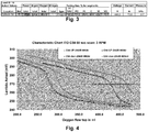
- Fig. 3 shows the settings used for the single layer sample of ITO produced in accordance with an example embodiment.
- This sample may be used to produce full stack samples.
- the Lambda set point was 272 mV, and the transport speed was 1m/min.
- the Ar gas was split 80% to the top gas inlet and 20% to the bottom.
- the oxygen flow on the bottom main bars was fixed to 90 seem, and trim oxygen, as well as the remaining total oxygen flow, was fed into the top gas inlets.
- the tube rotation speed was set at 3 RPM. All other samples discussed below were made with similar parameters, with the exception of variations in flow and Lambda settings specifically mentioned.
- Hysteresis loops of oxygen flow versus oxygen partial pressure were taken for the 600 and 800 sccm Ar settings using an automated procedure in the Lambda process control unit, which allows for the ramping of gas flow and the collection of data at a predefined time rate. This, in turn, allows the dynamic behavior of the process to be estimated, thus differentiating between geometric setups such as, for example, rotation speed, location of gas feeds, etc.
- a hysteresis loop is only representative if uniformity across the cathode is within a reasonable range, as the measured parameters are averages for the whole cathode and may be significantly distorted when a cathode is running in an asymmetric mode.
- different Ar flow rates likely will have an impact on hysteresis behavior, as will tube rotation speed and gas distribution between top and bottom gas.
- Fig. 4 compares the data taken for 600 sccm Ar and 800 sccm Ar flow at otherwise constant process conditions (e.g., power and gas distribution).
- the top main oxygen flow was first increased from 200 sccm to 500 sccm at a constant rate of 5ml/sec and, after settling the target for a few minutes, was reversed using the same ramp speed downwards.
- the oxygen flow values shown in the chart are only the variable part of the oxygen. To obtain the total oxygen flow, it is necessary to add the 90 sccm fed at the bottom and the 130 sccm used in the trim segments, which were both fixed during the test.
- the "UP" values are data taken when increasing the oxygen flow starting at low flow values, and these values are most appropriate for the conductive layers of certain example embodiments.
- the horizontal bar in the chart marks the Lambda sensor operating level required to obtain a low absorbing high conductive ITO layer. Surprisingly and unexpectedly, the operating point is inside the steep region of the transition from a metallic to an oxidic target surface coverage.
- the oxygen flow triggering the transition is about 40 sccm lower for the case with 800 sccm Ar compared to the 600 sccm Ar case.
- the higher Ar flow and the resulting higher process pressure leads to a higher target erosion rate, which is indeed confirmed by the samples run for these conditions at the same set point.
- a higher (metal) target erosion rate normally would require more oxygen to obtain a comparable composition in the film.
- the unusual behavior observed here may be explained by a higher target surface oxidation rate during the time the target surface is outside the eroding plasma caused by the higher pressure (more collisions with oxygen).
- the difference in the target surface oxidation seen here is possibly enhanced by the slow rotation speed and the reactive gas fed primarily at the back side of the tubes.
- Fig. 5 shows the transition chart obtained for 800 sccm Ar, with the rate of change in the Lambda signal included.
- a rate of change of approximately -2.0 to -3.5 mV/sec is observed for the given flow rate change.
- the rate is already too big to work with a flow control loop, which has about 1-2 sec response time itself because of the volume of the gas bars and the flow controller response. To overcome this challenge, it is possible to work a power control loop.
- Fig. 5 shows a considerable asymmetry in rate of change between the metal-to-oxide transition and the oxide-to-metal transition, which is much quicker and thus would be much more difficult to control.
- Performing this sort of analysis for different geometries of gas feed and tube rotation is useful in selecting favorable conditions for a given process requirement. In this case, it is desirable to keep the metal-to-oxide transition at the target as slow as possible, which was possibly achieved at the expense of the oxide-to-metal transition.
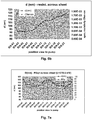
- Figs. 6a and 6b show the thickness and resistivity profiles for the low and high pressure samples, respectively.
- the films exhibit a similar thickness profile, which was not specifically tuned.
- thickness varies between about 82 to 100 nm, whereas it is between about 91 and 115 nm for the high pressure sample. Overall, this represents approximately a 10% increase in thickness due to the higher pressure.
- Specific resistivity was calculated from thickness and measured sheet resistance and is included in the chart.
- the resistivity variation is considerably smaller and thus indicates an improvement in compositional uniformity. Given the higher deposition rate together with the better compositional uniformity, the higher Ar flow was deemed desirable (although is not required for all embodiments of this invention) and was used for the following tests.
- Figs. 7a-f show a series of thickness and resistivity profiles for the varying Lambda control set points.
- the profile was initially tuned as finely as possible for a sample that still had about 15% absorption (ID15 shown in Fig. 7a ), and the set point was then lowered in steps of 1 mV to reduce overall absorption.
- the set point showing an absorption level of about 3-5% was chosen and re-tuned (ID25 shown in Fig. 7f ).
- Fig. 7f Making an appropriate adjustment in the trim gas for sample 25 ( Fig. 7f ), which was run at similar settings as ID20 ( Fig. 7c ) restores the uniformity profile.
- Fig. 8 shows the deviation from uniform distribution that was returned for all samples, although it may be desirable to at least somewhat reduce the amount of oxygen at the pump side, even for the ID25 sample.
- the tuning gas also was moved for each of the samples, and this is shown along the x-axis in Fig. 8 .
- the tuning chart shows the deviation in flow percent from a flat oxygen distribution taking into account the trim and main flow and the number of nozzles per segment.
- the correction on ID 25 was mainly a small increase of oxygen level at the view side, which helped thickness uniformity somewhat.
- to remove the pump side peak in sheet resistance would require a reducing in the PI segment, which should also reduce the tilt in thickness uniformity toward the pump side.
- Fig. 9a is the ID25 sample discussed in the previous section, which seems to have slightly too much oxygen at the pump side. The absorption does not show the full details of the center peak, but clearly has a tilt toward the pump side. Also, it flattens out around 2.5%, which indicates that the film is already over oxidized in this region, which is the reason for the steep rise in sheet resistance.
- Fig. 9b shows sample ID10, which was an intermediate tuning sample with considerable non-uniformity and absorption. As shown in Fig. 9b , absorption follows fairly well the calculated thickness profile.
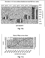
- Figs. 10a-c represent different ways to visualize the trim gas flows used during the tuning of the single layers. These visualizations are illustrative. ID16 refers to the final setting which could be used for the production of full stack samples.
- Fig. 10a plots the flow values as entered and displayed on the console.
- Fig. 10b plots the difference between the actual flow values and the ideal flat distribution for the given amount of tuning gas. This simply takes into account the number of nozzles for the different segments.
- Fig. 10c finally plots the relative deviation of flow values in percent compared to a flat gas feed situation taking into account the total oxygen gas flow (including main flow).
- a user interface may be configured to enable a user to adjust and display trim settings as relative deviations from a flat gas distribution.
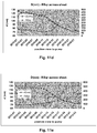
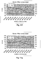
- Figs. 11a-h summarize the moves in trim gas settings to obtain a reasonably flat thickness and resistance profile.
- the figures and the analysis provide hints as to the sensitivity of trim gas moves. They also show that, in essence, the final trim profiles seen as the best look surprisingly similar when viewed under appropriate scaling.
- This means that the uniformity profile is primarily a pattern defined by the cathode bay (pumps) or the target / magnetbars, and not a random variation. Even as the uniformity may be limited for the current setup by factors that may not be changed by the trim gas settings, there is a good chance to obtain further improvements by working on the geometry of the deposition bay / cathode.
- Fig. 11a shows the starting point for the tuning.
- the trim gas move performed before second sample was too much and flipped the thickness profile completely. From there, gradual moves were taken to flatten the thickness distribution.
- the final settings on ID16 (in Fig. 11h ) look reasonably flat for thickness uniformity despite the characteristic peak in the center. However, based on resistance and the small tilt in thickness toward the pump side there still may be too much oxygen flowing at the pump side segments.
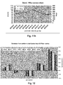
- Fig. 12 summarizes the trim gas moves discussed above and shows the relative deviation of oxygen flow from a flat distribution. Based on Fig. 12 , it appears that only a minor adjustment was required to get to ID16 from to the starting set of ID02. The problem was rather the overshooting in the second step and the gradual reversal of that setting.
- the overall pressure variation across the coat bay was calculated for the best two settings ID16 (see Figs. 12 and 13a ) and ID25 (see Figs. 8 and 13b ) taking into account pump speed variation and gas flow distribution as set.
- the calculated pressure profile matches fairly well with the inverted thickness profiles. In both cases, the overall pressure is significantly lower in the center compared to the edges given the current trim gas settings. There likely are settings that could avoid this pressure drop. However, changing these setting may affect the compositional uniformity. Thus, other approaches for the trim gas to target a flat "pressure" profile may be possible. Still further, changes may be made on the hardware to reduce the required asymmetry of the gas settings.
- One possible hardware modification involves shimming the pump slits around the center Turbo.
- Another possible modification involves the use of adjustable magnet bars to reduce of the sputter rate in the center.
- One risk associated with magnet bar tuning is that the required settings may be inverse to the settings required when running films in oxidic mode in the standard setting. In oxide mode (e.g., for SnO 2 , ZnO, etc., production) the thickness profile typically is at its low point in the center. This is most likely caused by the fact that Ar pressure variations dominate the erosion rate, and low pressure at the center is observed because of the location of the pumps. For a process run on the metallic side the reactive gas (oxygen) dominates the rate but, here, low oxygen pressure increases the rate so a reversal may be expected. Therefore, if the non-uniformity is pressure driven, only pump port adjustments would lead to an improvement for both scenarios.
- Flow values tend to be equipment-specific terms, as they tend to depend on cathode and chamber size, pump speed, and/or the like.
- the pressure ranges appropriate for certain example embodiments correspond to about 10 -3 to 10 -2 mbar (or even higher), with greater detail shown in Figs. 13a and 13b for the example embodiments described herein.
- a more preferable pressure range is about 5x10 -3 to 10 -2 mbar (or even higher), and a yet more preferable pressure range is about 7x10 -3 to 10 -2 mbar (or even higher).
- a particular layer or coating may be said to be “on” or “supported by” a surface or another coating (directly or indirectly), other layer(s) and/or coatings may be provided therebetween.
- a coating may be considered “on” and “supported by” a surface even if other layer(s) are provided between layer(s) and the substrate.
- certain layers or coatings may be removed in certain embodiments, while others may be added in other embodiments of this invention without departing from the overall spirit of certain embodiments of this invention.
- an encapsulating coating applied in liquid sol-gel form in accordance with an example embodiment may be said to be "on” or “supported by” a sputtering target material, even though other coatings and/or layers may be provided between the sol-gel formed coating and the target material.
Landscapes
- Chemical & Material Sciences (AREA)
- Engineering & Computer Science (AREA)
- Physics & Mathematics (AREA)
- Plasma & Fusion (AREA)
- Analytical Chemistry (AREA)
- Chemical Kinetics & Catalysis (AREA)
- Materials Engineering (AREA)
- Mechanical Engineering (AREA)
- Metallurgy (AREA)
- Organic Chemistry (AREA)
- Fluid Mechanics (AREA)
- Physical Vapour Deposition (AREA)
Applications Claiming Priority (2)
| Application Number | Priority Date | Filing Date | Title |
|---|---|---|---|
| US12/320,904 US20100200395A1 (en) | 2009-02-06 | 2009-02-06 | Techniques for depositing transparent conductive oxide coatings using dual C-MAG sputter apparatuses |
| EP10152525.1A EP2216424B1 (en) | 2009-02-06 | 2010-02-03 | Techniques for depositing transparent conductive oxide coatings using dual C-MAG sputter apparatuses |
Related Parent Applications (1)
| Application Number | Title | Priority Date | Filing Date |
|---|---|---|---|
| EP10152525.1A Division EP2216424B1 (en) | 2009-02-06 | 2010-02-03 | Techniques for depositing transparent conductive oxide coatings using dual C-MAG sputter apparatuses |
Publications (1)
| Publication Number | Publication Date |
|---|---|
| EP3293282A1 true EP3293282A1 (en) | 2018-03-14 |
Family
ID=42173162
Family Applications (2)
| Application Number | Title | Priority Date | Filing Date |
|---|---|---|---|
| EP17198035.2A Withdrawn EP3293282A1 (en) | 2009-02-06 | 2010-02-03 | Techniques for depositing transparent conductive oxide coatings using dual c-mag sputter apparatuses |
| EP10152525.1A Not-in-force EP2216424B1 (en) | 2009-02-06 | 2010-02-03 | Techniques for depositing transparent conductive oxide coatings using dual C-MAG sputter apparatuses |
Family Applications After (1)
| Application Number | Title | Priority Date | Filing Date |
|---|---|---|---|
| EP10152525.1A Not-in-force EP2216424B1 (en) | 2009-02-06 | 2010-02-03 | Techniques for depositing transparent conductive oxide coatings using dual C-MAG sputter apparatuses |
Country Status (4)
| Country | Link |
|---|---|
| US (1) | US20100200395A1 (pl) |
| EP (2) | EP3293282A1 (pl) |
| ES (1) | ES2656429T3 (pl) |
| PL (1) | PL2216424T3 (pl) |
Families Citing this family (13)
| Publication number | Priority date | Publication date | Assignee | Title |
|---|---|---|---|---|
| DE102009015737B4 (de) * | 2009-03-31 | 2013-12-12 | Fraunhofer-Gesellschaft zur Förderung der angewandten Forschung e.V. | Magnetron-Beschichtungsmodul sowie Magnetron-Beschichtungsverfahren |
| DE102009061065A1 (de) * | 2009-06-26 | 2011-09-29 | Von Ardenne Anlagentechnik Gmbh | Verfahren zur Beschichtung eines Subtrates in einer Vakuumkammer mit einem rotierenden Magnetron |
| EP2661514B1 (en) | 2011-01-06 | 2020-06-17 | Bühler AG | Magnetron assembly and sputtering system comprising the same |
| DE102011012034A1 (de) * | 2011-02-22 | 2012-08-23 | Heraeus Materials Technology Gmbh & Co. Kg | Rohrförmiges Sputtertarget |
| JP6244103B2 (ja) | 2012-05-04 | 2017-12-06 | ヴァイアヴィ・ソリューションズ・インコーポレイテッドViavi Solutions Inc. | 反応性スパッタ堆積のための方法および反応性スパッタ堆積システム |
| WO2014031156A1 (en) * | 2012-08-24 | 2014-02-27 | Cardinal Cg Company | Apparatus for cylindrical magnetron sputtering |
| US10138541B2 (en) * | 2012-08-31 | 2018-11-27 | Kaneka Corporation | Method for producing substrate with transparent electrode, and substrate with transparent electrode |
| KR102101720B1 (ko) * | 2012-09-04 | 2020-04-21 | 뷔홀러 아게 | 스퍼터링 장치 |
| DE102014103740B4 (de) * | 2014-01-09 | 2018-11-15 | VON ARDENNE Asset GmbH & Co. KG | Sputteranordnung und Sputter-Verfahren |
| WO2016185714A1 (ja) * | 2015-05-19 | 2016-11-24 | 株式会社アルバック | マグネトロンスパッタリング装置用の回転式カソードユニット |
| CN106595161A (zh) * | 2016-10-24 | 2017-04-26 | 杨瑞鹏 | 一种新型pvd旋转靶制造用冷却背管 |
| CN111155062B (zh) * | 2019-12-31 | 2021-12-03 | 中山市博顿光电科技有限公司 | 靶材旋转结构、靶材安装结构以及离子源溅射系统 |
| CN114277348B (zh) * | 2021-12-27 | 2023-06-30 | 晋能清洁能源科技股份公司 | Hjt电池生产中操控磁控溅射设备的方法 |
Citations (9)
| Publication number | Priority date | Publication date | Assignee | Title |
|---|---|---|---|---|
| WO1992001081A1 (en) * | 1990-07-06 | 1992-01-23 | The Boc Group, Inc. | Method and apparatus for co-sputtering and cross-sputtering homogeneous films |
| US5262032A (en) | 1991-05-28 | 1993-11-16 | Leybold Aktiengesellschaft | Sputtering apparatus with rotating target and target cooling |
| US5284564A (en) | 1991-07-30 | 1994-02-08 | Leybold Aktiengesellschaft | Magnetron sputtering cathode for vacuum coating apparatus |
| US5317006A (en) | 1989-06-15 | 1994-05-31 | Microelectronics And Computer Technology Corporation | Cylindrical magnetron sputtering system |
| US5403458A (en) | 1993-08-05 | 1995-04-04 | Guardian Industries Corp. | Sputter-coating target and method of use |
| US5527439A (en) | 1995-01-23 | 1996-06-18 | The Boc Group, Inc. | Cylindrical magnetron shield structure |
| US5591314A (en) | 1995-10-27 | 1997-01-07 | Morgan; Steven V. | Apparatus for affixing a rotating cylindrical magnetron target to a spindle |
| US20020134670A1 (en) * | 2001-01-23 | 2002-09-26 | Hiroshi Echizen | Sputtering method and sputtering apparatus |
| WO2004106581A2 (en) * | 2003-05-23 | 2004-12-09 | Symmorphix, Inc. | Transparent conductive oxides |
Family Cites Families (10)
| Publication number | Priority date | Publication date | Assignee | Title |
|---|---|---|---|---|
| US3639151A (en) * | 1969-03-13 | 1972-02-01 | United Aircraft Corp | Vapor randomization in vacuum deposition of coatings |
| DE3331707A1 (de) * | 1983-09-02 | 1985-03-21 | Leybold-Heraeus GmbH, 5000 Köln | Verfahren und vorrichtung zum reaktiven aufstaeuben von verbindungen von metallen und halbleitern |
| JP3782608B2 (ja) * | 1998-05-22 | 2006-06-07 | キヤノン株式会社 | 薄膜材料および薄膜作成法 |
| US6488824B1 (en) * | 1998-11-06 | 2002-12-03 | Raycom Technologies, Inc. | Sputtering apparatus and process for high rate coatings |
| JP3976166B2 (ja) * | 2001-07-13 | 2007-09-12 | 持田商工株式会社 | Pdpパネル |
| US7378356B2 (en) * | 2002-03-16 | 2008-05-27 | Springworks, Llc | Biased pulse DC reactive sputtering of oxide films |
| US7166199B2 (en) * | 2002-12-18 | 2007-01-23 | Cardinal Cg Company | Magnetron sputtering systems including anodic gas distribution systems |
| US7791017B2 (en) * | 2007-07-23 | 2010-09-07 | Schlumberger Technology Corporation | Method to simultaneously determine pore hydrocarbon density and water saturation from pulsed neutron measurements |
| US8409717B2 (en) * | 2008-04-21 | 2013-04-02 | Guardian Industries Corp. | Coated article with IR reflecting layer and method of making same |
| US20100132783A1 (en) * | 2008-12-02 | 2010-06-03 | Applied Materials, Inc. | Transparent conductive film with high surface roughness formed by a reactive sputter deposition |
-
2009
- 2009-02-06 US US12/320,904 patent/US20100200395A1/en not_active Abandoned
-
2010
- 2010-02-03 EP EP17198035.2A patent/EP3293282A1/en not_active Withdrawn
- 2010-02-03 ES ES10152525.1T patent/ES2656429T3/es active Active
- 2010-02-03 EP EP10152525.1A patent/EP2216424B1/en not_active Not-in-force
- 2010-02-03 PL PL10152525T patent/PL2216424T3/pl unknown
Patent Citations (9)
| Publication number | Priority date | Publication date | Assignee | Title |
|---|---|---|---|---|
| US5317006A (en) | 1989-06-15 | 1994-05-31 | Microelectronics And Computer Technology Corporation | Cylindrical magnetron sputtering system |
| WO1992001081A1 (en) * | 1990-07-06 | 1992-01-23 | The Boc Group, Inc. | Method and apparatus for co-sputtering and cross-sputtering homogeneous films |
| US5262032A (en) | 1991-05-28 | 1993-11-16 | Leybold Aktiengesellschaft | Sputtering apparatus with rotating target and target cooling |
| US5284564A (en) | 1991-07-30 | 1994-02-08 | Leybold Aktiengesellschaft | Magnetron sputtering cathode for vacuum coating apparatus |
| US5403458A (en) | 1993-08-05 | 1995-04-04 | Guardian Industries Corp. | Sputter-coating target and method of use |
| US5527439A (en) | 1995-01-23 | 1996-06-18 | The Boc Group, Inc. | Cylindrical magnetron shield structure |
| US5591314A (en) | 1995-10-27 | 1997-01-07 | Morgan; Steven V. | Apparatus for affixing a rotating cylindrical magnetron target to a spindle |
| US20020134670A1 (en) * | 2001-01-23 | 2002-09-26 | Hiroshi Echizen | Sputtering method and sputtering apparatus |
| WO2004106581A2 (en) * | 2003-05-23 | 2004-12-09 | Symmorphix, Inc. | Transparent conductive oxides |
Also Published As
| Publication number | Publication date |
|---|---|
| EP2216424A1 (en) | 2010-08-11 |
| ES2656429T3 (es) | 2018-02-27 |
| US20100200395A1 (en) | 2010-08-12 |
| PL2216424T3 (pl) | 2018-04-30 |
| EP2216424B1 (en) | 2017-11-08 |
Similar Documents
| Publication | Publication Date | Title |
|---|---|---|
| EP2216424B1 (en) | Techniques for depositing transparent conductive oxide coatings using dual C-MAG sputter apparatuses | |
| EP3211119B1 (en) | Methof of sputtering and sputter system | |
| EP2640865B1 (en) | Soft sputtering magnetron system | |
| US20090236218A1 (en) | Method for depositing multilayer coatings | |
| JP2016509134A (ja) | 誘電性化学量論薄膜の高速反応性スパッタリング | |
| EP2378538A2 (en) | Ring cathode for use in a magnetron sputtering device | |
| US20120255855A1 (en) | Method of controlling lithium uniformity | |
| US7935232B2 (en) | Sputtering apparatus and method, and sputtering control program | |
| EP2616566B1 (en) | Improved method of co-sputtering alloys and compounds using a dual c-mag cathode arrangement and corresponding apparatus | |
| KR20140127352A (ko) | 성막장치 및 성막방법 | |
| US6783640B2 (en) | Sputtering method and sputtering apparatus | |
| JP2020019991A (ja) | 成膜装置及び電子デバイスの製造方法 | |
| JP2018150590A (ja) | 反応性スパッタリングの成膜装置、および成膜方法 | |
| JP2002180247A (ja) | 透明導電積層体の製造方法および製造装置 | |
| KR102099601B1 (ko) | 프로세스 챔버로의 가스 공급을 제어하기 위한 방법, 프로세스 챔버로의 가스 공급을 제어하기 위한 제어기, 및 장치 | |
| JP2007119829A (ja) | スパッタ成膜装置 | |
| JP2013237910A (ja) | 意匠性鋼板の製造方法 | |
| KR200158394Y1 (ko) | 반도체 소자 제조를 위한 스퍼터링 시스템의 자기장 자동 조절장치 | |
| CN117947390A (zh) | 一种疏松氧化物薄膜的制备方法 | |
| KR20010108016A (ko) | 가변 자석 구조를 가진 캐소드 | |
| Geisler et al. | Latest Developments of Large Area Coater and Application | |
| Linss et al. | Reactive Sputtering of TCO Films Using Rotatable Magnetrons–Process Control Features and Film Properties | |
| JP2006176862A (ja) | スパッタ成膜装置およびスパッタ成膜方法 |
Legal Events
| Date | Code | Title | Description |
|---|---|---|---|
| PUAI | Public reference made under article 153(3) epc to a published international application that has entered the european phase |
Free format text: ORIGINAL CODE: 0009012 |
|
| STAA | Information on the status of an ep patent application or granted ep patent |
Free format text: STATUS: THE APPLICATION HAS BEEN PUBLISHED |
|
| AC | Divisional application: reference to earlier application |
Ref document number: 2216424 Country of ref document: EP Kind code of ref document: P |
|
| AK | Designated contracting states |
Kind code of ref document: A1 Designated state(s): AT BE BG CH CY CZ DE DK EE ES FI FR GB GR HR HU IE IS IT LI LT LU LV MC MK MT NL NO PL PT RO SE SI SK SM TR |
|
| STAA | Information on the status of an ep patent application or granted ep patent |
Free format text: STATUS: REQUEST FOR EXAMINATION WAS MADE |
|
| GRAP | Despatch of communication of intention to grant a patent |
Free format text: ORIGINAL CODE: EPIDOSNIGR1 |
|
| STAA | Information on the status of an ep patent application or granted ep patent |
Free format text: STATUS: GRANT OF PATENT IS INTENDED |
|
| 17P | Request for examination filed |
Effective date: 20180829 |
|
| RBV | Designated contracting states (corrected) |
Designated state(s): AT BE BG CH CY CZ DE DK EE ES FI FR GB GR HR HU IE IS IT LI LT LU LV MC MK MT NL NO PL PT RO SE SI SK SM TR |
|
| RIC1 | Information provided on ipc code assigned before grant |
Ipc: C23C 14/35 20060101ALI20180913BHEP Ipc: H01J 37/34 20060101ALI20180913BHEP Ipc: H01J 37/32 20060101ALI20180913BHEP Ipc: C23C 14/00 20060101AFI20180913BHEP |
|
| INTG | Intention to grant announced |
Effective date: 20181004 |
|
| STAA | Information on the status of an ep patent application or granted ep patent |
Free format text: STATUS: THE APPLICATION IS DEEMED TO BE WITHDRAWN |
|
| 18D | Application deemed to be withdrawn |
Effective date: 20190215 |