EP3292806A1 - Récipient de mélange pour un robot ménager électrique - Google Patents
Récipient de mélange pour un robot ménager électrique Download PDFInfo
- Publication number
- EP3292806A1 EP3292806A1 EP17189150.0A EP17189150A EP3292806A1 EP 3292806 A1 EP3292806 A1 EP 3292806A1 EP 17189150 A EP17189150 A EP 17189150A EP 3292806 A1 EP3292806 A1 EP 3292806A1
- Authority
- EP
- European Patent Office
- Prior art keywords
- vessel
- agitator
- foot part
- vessel bottom
- fixing
- Prior art date
- Legal status (The legal status is an assumption and is not a legal conclusion. Google has not performed a legal analysis and makes no representation as to the accuracy of the status listed.)
- Granted
Links
- 230000000903 blocking effect Effects 0.000 claims abstract description 70
- 235000013305 food Nutrition 0.000 claims abstract description 39
- 238000003756 stirring Methods 0.000 claims description 12
- 230000013011 mating Effects 0.000 claims description 11
- 238000009434 installation Methods 0.000 abstract 1
- 238000006073 displacement reaction Methods 0.000 description 4
- 238000003780 insertion Methods 0.000 description 3
- 230000037431 insertion Effects 0.000 description 3
- 230000007797 corrosion Effects 0.000 description 2
- 238000005260 corrosion Methods 0.000 description 2
- 239000000834 fixative Substances 0.000 description 2
- 229910000760 Hardened steel Inorganic materials 0.000 description 1
- 229910000963 austenitic stainless steel Inorganic materials 0.000 description 1
- 230000015572 biosynthetic process Effects 0.000 description 1
- 238000004140 cleaning Methods 0.000 description 1
- 239000011248 coating agent Substances 0.000 description 1
- 238000000576 coating method Methods 0.000 description 1
- 150000001875 compounds Chemical class 0.000 description 1
- 230000008878 coupling Effects 0.000 description 1
- 238000010168 coupling process Methods 0.000 description 1
- 238000005859 coupling reaction Methods 0.000 description 1
- 238000002788 crimping Methods 0.000 description 1
- 239000013013 elastic material Substances 0.000 description 1
- 239000003365 glass fiber Substances 0.000 description 1
- 230000003993 interaction Effects 0.000 description 1
- 239000007788 liquid Substances 0.000 description 1
- 229910000734 martensite Inorganic materials 0.000 description 1
- 239000002184 metal Substances 0.000 description 1
- 238000002360 preparation method Methods 0.000 description 1
- 230000000750 progressive effect Effects 0.000 description 1
Images


Classifications
-
- A—HUMAN NECESSITIES
- A47—FURNITURE; DOMESTIC ARTICLES OR APPLIANCES; COFFEE MILLS; SPICE MILLS; SUCTION CLEANERS IN GENERAL
- A47J—KITCHEN EQUIPMENT; COFFEE MILLS; SPICE MILLS; APPARATUS FOR MAKING BEVERAGES
- A47J43/00—Implements for preparing or holding food, not provided for in other groups of this subclass
- A47J43/04—Machines for domestic use not covered elsewhere, e.g. for grinding, mixing, stirring, kneading, emulsifying, whipping or beating foodstuffs, e.g. power-driven
- A47J43/046—Machines for domestic use not covered elsewhere, e.g. for grinding, mixing, stirring, kneading, emulsifying, whipping or beating foodstuffs, e.g. power-driven with tools driven from the bottom side
-
- A—HUMAN NECESSITIES
- A47—FURNITURE; DOMESTIC ARTICLES OR APPLIANCES; COFFEE MILLS; SPICE MILLS; SUCTION CLEANERS IN GENERAL
- A47J—KITCHEN EQUIPMENT; COFFEE MILLS; SPICE MILLS; APPARATUS FOR MAKING BEVERAGES
- A47J43/00—Implements for preparing or holding food, not provided for in other groups of this subclass
- A47J43/04—Machines for domestic use not covered elsewhere, e.g. for grinding, mixing, stirring, kneading, emulsifying, whipping or beating foodstuffs, e.g. power-driven
- A47J43/07—Parts or details, e.g. mixing tools, whipping tools
- A47J43/075—Safety devices
- A47J43/0761—Safety devices for machines with tools driven from the lower side
-
- A—HUMAN NECESSITIES
- A47—FURNITURE; DOMESTIC ARTICLES OR APPLIANCES; COFFEE MILLS; SPICE MILLS; SUCTION CLEANERS IN GENERAL
- A47J—KITCHEN EQUIPMENT; COFFEE MILLS; SPICE MILLS; APPARATUS FOR MAKING BEVERAGES
- A47J43/00—Implements for preparing or holding food, not provided for in other groups of this subclass
- A47J43/04—Machines for domestic use not covered elsewhere, e.g. for grinding, mixing, stirring, kneading, emulsifying, whipping or beating foodstuffs, e.g. power-driven
- A47J43/07—Parts or details, e.g. mixing tools, whipping tools
- A47J43/0716—Parts or details, e.g. mixing tools, whipping tools for machines with tools driven from the lower side
-
- A—HUMAN NECESSITIES
- A47—FURNITURE; DOMESTIC ARTICLES OR APPLIANCES; COFFEE MILLS; SPICE MILLS; SUCTION CLEANERS IN GENERAL
- A47J—KITCHEN EQUIPMENT; COFFEE MILLS; SPICE MILLS; APPARATUS FOR MAKING BEVERAGES
- A47J43/00—Implements for preparing or holding food, not provided for in other groups of this subclass
- A47J43/04—Machines for domestic use not covered elsewhere, e.g. for grinding, mixing, stirring, kneading, emulsifying, whipping or beating foodstuffs, e.g. power-driven
- A47J43/07—Parts or details, e.g. mixing tools, whipping tools
- A47J43/075—Safety devices
- A47J43/0761—Safety devices for machines with tools driven from the lower side
- A47J43/0766—Safety devices for machines with tools driven from the lower side activated by the proper positioning of the mixing bowl
-
- B—PERFORMING OPERATIONS; TRANSPORTING
- B01—PHYSICAL OR CHEMICAL PROCESSES OR APPARATUS IN GENERAL
- B01F—MIXING, e.g. DISSOLVING, EMULSIFYING OR DISPERSING
- B01F35/00—Accessories for mixers; Auxiliary operations or auxiliary devices; Parts or details of general application
- B01F35/30—Driving arrangements; Transmissions; Couplings; Brakes
- B01F35/32—Driving arrangements
- B01F35/32005—Type of drive
- B01F35/3204—Motor driven, i.e. by means of an electric or IC motor
-
- B—PERFORMING OPERATIONS; TRANSPORTING
- B02—CRUSHING, PULVERISING, OR DISINTEGRATING; PREPARATORY TREATMENT OF GRAIN FOR MILLING
- B02C—CRUSHING, PULVERISING, OR DISINTEGRATING IN GENERAL; MILLING GRAIN
- B02C18/00—Disintegrating by knives or other cutting or tearing members which chop material into fragments
- B02C18/06—Disintegrating by knives or other cutting or tearing members which chop material into fragments with rotating knives
- B02C18/08—Disintegrating by knives or other cutting or tearing members which chop material into fragments with rotating knives within vertical containers
- B02C18/12—Disintegrating by knives or other cutting or tearing members which chop material into fragments with rotating knives within vertical containers with drive arranged below container
-
- B—PERFORMING OPERATIONS; TRANSPORTING
- B02—CRUSHING, PULVERISING, OR DISINTEGRATING; PREPARATORY TREATMENT OF GRAIN FOR MILLING
- B02C—CRUSHING, PULVERISING, OR DISINTEGRATING IN GENERAL; MILLING GRAIN
- B02C23/00—Auxiliary methods or auxiliary devices or accessories specially adapted for crushing or disintegrating not provided for in preceding groups or not specially adapted to apparatus covered by a single preceding group
- B02C23/04—Safety devices
-
- B—PERFORMING OPERATIONS; TRANSPORTING
- B01—PHYSICAL OR CHEMICAL PROCESSES OR APPARATUS IN GENERAL
- B01F—MIXING, e.g. DISSOLVING, EMULSIFYING OR DISPERSING
- B01F2101/00—Mixing characterised by the nature of the mixed materials or by the application field
- B01F2101/06—Mixing of food ingredients
Definitions
- the invention relates to a mixing vessel for an electric motor driven food processor, with a vessel bottom, a projecting through the vessel bottom in the agitator agitator and an externally connectable to the vessel bottom foot part, which is designed for fixing the agitator to the vessel bottom.
- the invention relates to an electric motor driven food processor with a base unit and a connectable to the base unit mixing vessel.
- Rlickgefäße of the type in question are known, for example from the DE 10 2010 016 667 A1 or the EP 2 875 762 B1 ,
- the mixing vessels are used in particular in connection with an electric motor driven food processor, more particularly for the household sector.
- a vessel bottom of the mixing vessel is associated with a stirrer, for example in the form of a knife work.
- An agitator shaft of the agitator passes through the vessel bottom, in particular for the formation of a coupling driver projecting freely downwards over the vessel bottom.
- the mixing vessel in a mixing vessel receptacle of a base unit of the food processor, in which the mixing vessel is on a footprint with the aid of a pot-like foot part.
- Such a foot also serves in a known manner for stopping the mixing vessel on a work surface or the like after removal from the food processor.
- the agitator for example, for cleaning purposes and / or for the purpose of replacement releasably attached to the mixing vessel.
- the agitator can be arranged for example by means of a bayonet-type attachment to the vessel bottom, this further preferably with involvement and fixing of the foot part of the mixing vessel.
- the agitator passes through the vessel bottom with a rotationally fixed to the vessel bottom can be arranged bearing body, which may be formed in one or more parts.
- the bearing body is again penetrated by the agitator shaft.
- it is further known to provide for rotational fixing to the vessel bottom wall outside the bearing body projections which cooperate with a corresponding contour of an opening of the vessel bottom and / or the foot part.
- the vessel bottom or the foot part acted upon by a spring force of a spring element blocking element which by means of a corresponding contact element of the foot part or the vessel bottom of a fixing of the agitator preventing blocking position against the spring force in a fixation enabling Release position is relocatable.
- the foot part may also have a blocking element acted upon by a spring force of a spring element.
- the corresponding contact element is located at the bottom of the vessel.
- the blocking element arranged either on the vessel bottom or the foot part can, for example, have a separate spring element, for example a helical spring, leg spring, spiral spring, torsion spring and the like, or can itself be formed from an elastic material, so that the blocking element itself is a spring element providing a spring force.
- the blocking element may for example be formed of metal, preferably made of corrosion-resistant austenitic stainless steel or martensitic hardened steel with corrosion protection coating.
- the blocking element may also be made of plastic, for example of a glass fiber plastic or the like.
- the contact element arranged on the foot part or the bottom of the vessel is arranged and designed such that it protrudes into a displacement path of the blocking element (relative to a position of the foot part arranged on the mixing vessel), which the blocking element passes from the release position into the blocking position, and vice versa ,
- the foot part is usually rotated relative to the bottom of the vessel (about an axis of rotation of the agitator), whereby the abutment element presses against the blocking element.
- the abutment element can be a pin, projection, wall part region or the like formed on the vessel bottom or the foot part.
- the blocking element is arranged on the vessel bottom or the foot part, that this protrudes relative to a relaxed state of the spring element in a trained for a connection of the mixing vessel with an electric motor driven kitchen machine connection area and thus prevents a connection.
- the blocking element is thus located in the blocking position in a region in which, when the mixing vessel is correctly connected to the basic appliance of the food processor, corresponding elements interlock, contact or the like. If the blocking element is displaced into the release position, these elements can be guided in the usual way to each other, so that the stirring vessel can be used in the food processor.
- the blocking element projects into this connection area, this presents an obstacle which prevents the connection between the mixing vessel and the mixing vessel receptacle of the food processor.
- the mixing vessel can thereby be inclined in the mixing vessel receptacle, have too large a height, which prevents locking of the mixing vessel with a lid or the like.
- connection region has electrical contacts for connection to corresponding mating contacts of an electric motor driven food processor. If the agitator is not inserted into the vessel bottom, a fixation between the agitator and the vessel bottom and thus between the foot and the bottom of the vessel can not be achieved. This can lead, for example, to the fact that the foot part can not be brought into a usual end position on the mixing vessel and the connecting region of the vessel bottom, which has the electrical contacts, is partially covered by a partial region of the foot part, so that the electrical contacts are not connected to Mating contacts of the food processor can be brought.
- the addressed portion of the foot can thereby on the mating contacts rest and thus cause a relation to the properly assembled training of the mixing vessel increased height of the mixing vessel or an inclination of the mixing vessel in the food processor.
- This embodiment is suitable both for embodiments in which the blocking element is arranged on the vessel bottom, as well as for embodiments in which the blocking element is arranged on the foot part.
- a cover of at least one of the electrical contacts of the mixing vessel can be achieved within the connection region.
- the blocking element is a pawl which is arranged pivotably on the vessel bottom and which is pivotable about a pivot axis arranged perpendicular to the vessel bottom.
- the blocking element is arranged on the vessel bottom of the mixing vessel.
- the blocking element is pivotable within a plane which is aligned parallel to the plane of the vessel bottom.
- the blocking element is a sliding bolt arranged movably on the foot part, which in relation to a connected state of the vessel bottom and foot part is displaceable in a plane parallel to the vessel bottom.
- the locking bolt is arranged in the release position at a portion of the foot part, that the locking bar does not protrude into a connection region of the vessel bottom, which is required for a proper connection of the mixing vessel with the electric motor driven food processor.
- the locking bolt may for example be a linear locking bolt, or a locking bolt, which is designed in the manner of a circular ring segment and is rotatable about a central opening of the foot part.
- the foot part can be fixed by rotation about an axis of rotation of the agitator to the agitator and / or the bottom of the vessel.
- the foot part for fixing the agitator on the vessel bottom (and thus also for a fixation of the foot part to the vessel bottom) is rotated about the axis of rotation.
- a contact element arranged on the foot part can be moved against the blocking element in a particularly simple manner or a blocking element arranged on the foot part can be moved against a contact element of the vessel bottom.
- the foot can not be clamped to the bottom of the vessel and acting on the blocking element spring element orsfedernd trained blocking element pushes the foot back into the blocking position, so that a user does not correct the mixing vessel can use in the food processor.
- the movement of the foot part for the fixation of the agitator on the bottom of the vessel is effected by the rotation about the axis of rotation of the agitator in a plane which corresponds to the pivot plane of the previously proposed pawl or the displacement plane of the previously proposed locking bar. This results in an optimal interaction within the meaning of the invention.
- the base part and a bearing body of the agitator bearing a agitator shaft have corresponding fixing means, which can be fixed to each other for a fixation of the agitator. It is provided that the fixing means can only be fixed to each other when the vessel bottom between the agitator and the foot part is arranged, which is the case regularly when the agitator is properly inserted into the mixing vessel.
- the agitator shaft then passes through a bottom opening of the vessel bottom until the fixing means of the bearing body protrude into a plane aligned parallel to the vessel bottom, in which the corresponding fixing means of the foot part are arranged.
- the fixing means of the foot part and the bearing body of the agitator can be fixed to each other, for example by latching, crimping or the like.
- the bearing body or the foot part each have at least one fixing means.
- the bearing body of the agitator has at least one bearing projection facing outward relative to an axis of rotation of the agitator, and that the foot part has a foot part opening for receiving the bearing body, wherein the foot part opening has at least one fixing ramp for fixing the bearing projection.
- the corresponding fixing means on the one hand on the bearing body arranged or formed bearing projection and arranged on the foot part or trained Fixierrampe, which in particular after the manner of a crimped connection to each other can be fixed.
- the bearing body has a plurality of bearing projections which are arranged in three mutually spaced planes, viewed in a direction parallel to the axis of rotation, the bearing projections having at least one fixing projection arranged in a first plane for engagement in a corresponding fixing means of the vessel bottom, have at least one disposed in a second plane bearing ramp and at least one arranged in a third plane fixing projection, wherein the fixing ramp of the foot part between the bearing ramp and the fixing projection is fixable.
- the fixing projection arranged in the first plane serves for engagement in a corresponding fixing means of the vessel bottom.
- the fixing means of the vessel bottom is a corresponding recess with respect to the shape of the fixing projection, in which the fixing projection can engage and thus prevents rotation of the agitator relative to the vessel bottom.
- the bearing ramp which is designed to interact with a corresponding fixing ramp of the foot part opening.
- the bearing ramp is formed in the manner of a saw tooth, the edge of which points in a direction corresponding to a direction of rotation of the foot part, which is required for releasing the fixation between the foot part and the agitator.
- the flank of the bearing ramp and the fixing ramp do not reach each other in the circumferential direction, so that a rotation of the foot part in both the reverse direction and in the release direction is possible. Only in the event that the bottom of the vessel is not between the foot and the agitator, the edge of the bearing ramp stops the rotation of the foot part.
- the fixing projection arranged in the third plane likewise projects into the interior of the foot part in the correct mounting position and is spaced from the second-level bearing ramp which is suitable for receiving the fixing ramp of the foot part opening, due to the pitch of the fixing ramp the Wegö réelle comes with progressive rotation of the foot part about the rotation axis to a jamming of agitator, foot and bottom of the vessel.
- an electric motor-driven food processor which has a base unit and a mixing vessel connectable to the base unit, which is equipped with one or more of the features previously described with respect to the mixing vessel.
- the features and advantages of the electromotive powered food processor arise analogous to the features and advantages described in relation to the mixing vessel.
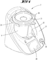
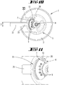
- FIG. 1 shows a food processor 2 according to the invention with a mixing vessel 1.
- the food processor 2 has a base unit 27 with a Rhakgefäßbefore, in which the mixing vessel 1 is inserted.
- a vessel bottom 3 is associated with a stirrer 4 (in FIG. 1 not shown), which is operable via a in the base unit 27 arranged, not shown electric drive.
- the mixing vessel 1 has a substantially vertically oriented handle 32, is pot-shaped with a circular cross-section and carries centrally arranged on the vessel bottom 3, the agitator 4.
- the vessel bottom 3 may be further associated with an electrical resistance heater.
- the base unit 27 of the food processor 2 further has a display 28 on which a selection menu, preparation instructions or the like can be displayed.
- a switch 29 is arranged, which is designed here as a rotary-key switch. About this one can the food processor 2 are turned on and off and on the other a selection are made, which is displayed for example on the display 28.
- the base unit 27 also has two locking rollers 30, which serve to lock the mixing vessel 1 with a lid 31.
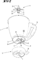
- FIG. 2 shows an exploded view of the mixing vessel 1 with removed agitator 4 and one of the vessel bottom 3 of the mixing vessel 1 removed foot 5.
- the agitator 4 is formed here as a knife bearing with a plurality of blades 33 which are rotatably connected to a stirrer shaft 14.
- the agitator shaft 14 is rotatably received in a bearing body 15 of the agitator 4, which can be passed through a bottom opening 34 of the vessel bottom 3 of the mixing vessel 1 in order to connect these rotatably with the vessel bottom 3.
- On the bearing body 15 a plurality of Fest GmbHsvorsprünge 23 are arranged, which can be guided by corresponding fixing means 24 of the bottom opening 34 of the vessel bottom 3.
- Each fixing means 24 is here a receiving area corresponding in its shape with a fixing projection 23. In the illustration, four such Fest einsvorsprünge 23 or fixing 24 are used.
- a plurality of electrical contacts 9 in the form of contact pins are arranged on the outside of the vessel bottom 3 in a connection region 8 which serves to connect to a corresponding connection region of the base device 27.
- the foot part 5 is as well as the mixing vessel 1 is substantially cup-shaped and serves as a receptacle for the vessel bottom 3 of the mixing vessel 1.
- the foot 5 provides a footing for the mixing vessel 1 ready to turn this example on a countertop, especially if the vessel bottom. 3 is heated by the heater.
- the electrical contacts 9 protrude into the interior of the foot part 5.
- the foot part 5 in turn can be connected in correspondence with the mixing vessel receptacle of the base unit 27 of the food processor 2. In this case, the electrical contacts 9 of the mixing vessel 1 come into contact with corresponding mating contacts of the base unit 27.
- the foot part 5 has a contact element 7, which acts in correctly mounted on the vessel bottom 3 state of the foot part 5 against the pawl 10 designed as a blocking element 6.
- the assembly of the foot part 5 on the bottom of the vessel 3 is carried out so that the foot part 5 is initially attached to the vessel bottom 3, that a predominantlyteilhandhabe 35 shows relative to a rotational axis 13 of the agitator 4 in a radial direction, which from a radial direction of the handle 32 of the mixing vessel 1 deviates. Then, the foot part 5 is rotated about the rotation axis 13, so that the proposedteilhandhabe 35 is pivoted to the handle 32. As a result of the rotation of the foot part 5, the contact element 7 arranged thereon is simultaneously displaced and comes into contact with the blocking element 6, ie the pawl 10.
- the contact element 7 presses the blocking element 6 against the restoring force of a spring element 36 from the electrical contact 9 away and out of the connection area 8, so that all electrical contacts 9 are freely accessible and can be connected when arranging the mixing vessel 1 in the base unit 27 with corresponding mating contacts. If the foot part 5 was not correctly mounted on the mixing vessel 1, the blocking element 6 protrudes into the connection region 8 and prevents the shape-corresponding connection between the mixing vessel 1 and the base unit 27th
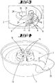
- FIG. 3 shows an enlarged section of the vessel bottom 3, in which the bottom opening 34 with the fixing means 24 and the connecting portion 8 with the electrical contacts 9, the blocking element 6 and the locking element 6 associated spring element 36 are arranged.
- FIG. 4 shows a perspective view in the foot part 5 of the mixing vessel 1.
- the foot part 5 has a contemplatteilö réelle 18, which is formed centrally on the foot part 5 and mounted on the bottom of the vessel 3 (and upright position of the mixing vessel 1) under the bottom opening 34 of Bottom of the vessel 3 is located, so that both the contemplatteilö réelle 18 and the bottom opening 34 are both arranged symmetrically to the rotation axis 13 and in the direction of the rotation axis 13 behind each other.
- the foot part opening 18 and the bottom opening 34 are substantially the same size, so that the bearing body 15 of the agitator 4 can be passed through both.
- the foot part opening 18 has fixing means 16, which correspond to corresponding bearing projections 17 of the agitator 4, in order to be able to clamp the agitator 4 to the bottom of the vessel 3 and the foot part 5.
- the fixing means 16 are formed here as fixing ramps 19.
- FIG. 4 shows further arranged on the foot part 5 contact element 7, which protrudes into the interior of the foot part 5, that this engages during assembly of the foot part 5 at the bottom of the vessel 3 in the connection region 8 of the vessel bottom 3 and optionally interacts there with the blocking element 6.
- FIG. 5 shows in detail the agitator 4 with the blades 33, which are rotatably connected to the agitator shaft 14.
- the agitator shaft 14 rotates about the rotation axis 13.
- a plurality of Fest GmbHsvorsprünge 23 are arranged, which serve for engagement in the fixing means 24 of the bottom opening 34 of the vessel bottom 3 of the mixing vessel 1.
- two bearing projections 17 are arranged below each Fest GmbHsvorsprungs 23, namely a bearing ramp 25 and a fixing projection 26. Based on the extension direction of the rotation axis 13 of the fixing projection 23 is arranged in a first plane 20.
- the bearing ramp 25 and the bearing ramps 25 are arranged in a second plane spaced therefrom 21 and the fixing projections 26 in a third plane 22.
- the Fest einsvorsprung 23 and the bearing ramp 25 go directly into each other, while the bearing ramp 25th and the fixing projection 26 are spaced apart in the direction of the axis of rotation 13, so that later in the arrangement of the agitator 4 and the foot part 5 at the bottom of the vessel 3, a corresponding fixing ramp 19 of the foot part 5 can be accommodated between them.
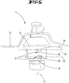
- FIG. 6 shows a arranged on the bottom of the vessel 3 state of the agitator 4.
- the fixing ramp 19 of the foot part 5 between the bearing ramp 25 and the fixing projection 26 of the bearing body 15 of the agitator 4 is performed.
- the fixing means 24 of the bottom opening 34 of the vessel bottom 3 and the fixing projections 23 of the bearing body 15 are engaged with each other, so that the fixing of the bearing body 15 on the base part 5 takes place at the same time fixing the vessel bottom 3.
- both the vessel bottom 3, and the agitator 4 and the foot part 5 are connected to each other, namely here via a crimp connection.
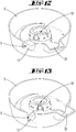
- FIG. 7 shows a bottom view of the mixing vessel 1 to the level of the vessel bottom 3.
- the fixing means 24 which are formed for receiving the Fest GmbHsvorsprünge 23 of the bearing body 15 of the agitator 4, and the connecting portion 8 of the vessel bottom 3, in which five electrical contacts 9 are formed.
- At one of the electrical contacts 9 is formed as a pawl 10 blocking element 6 at.
- the locking element 6 is pivotable about the pivot axis 11 and acted upon by the force of the spring element 36, which is designed here as a leg spring.
- the restoring force of the spring element 36 points in the direction of the electrical contact 9 against which the blocking element 6 rests in the blocking position.
- a release order is shown in dashed lines.
- This release position can reach the locking element 6 when overcoming the restoring force of the spring element 36.
- To overcome the restoring force is arranged on the foot part 5 contact element 7, which can press the locking element 6 from the voltage applied to the electrical contact 9 blocking position in the dashed line release position.
- FIG. 8 shows a bottom view of the mixing vessel 1 with disposed thereon foot part.
- FIG. 9 shows an enlarged section of it.
- the foot part 5 is located in a non-rotatably arranged on the mixing vessel 1 state.
- the carteteilhandhabe 35 and the handle 32 of the mixing vessel 1 are not yet aligned in the same radial direction relative to the axis of rotation 13 of the agitator 4.
- the blocking element 6 of the mixing vessel 1 Based on the blocking element 6 of the mixing vessel 1, this corresponds to the blocking position in which the blocking element 6 protrudes into the connecting region 8 of the mixing vessel, a part of the connecting region 8 is shaded by the foot part 5 and the electrical contacts 9 of the mixing vessel 1 as a result not with corresponding Mating contacts of the base unit 27 of the food processor 2 can be connected.
- the shape-corresponding connection between the mixing vessel 1 and the base unit 27 fails, firstly, because the foot part handle 35 protrudes beyond the handle 32 and, secondly, because of the contact of the blocking element 6 at the electrical contact 9, which prevents a shape-corresponding insertion of the electrical contacts 9 in the corresponding mating contacts of the base unit 27.
- FIG. 10 shows the contrast, the release position of the locking element 6, in which the locking element 6 is pushed out by means of the contact element 7 from the connecting portion 8.
- this release position are the handle 32 of the mixing vessel 1 and the predominantlyteilhandhabe 35 of the foot 5 in the same radial direction with respect to the axis of rotation 13 of the agitator 4.
- the restoring force of the spring element 36 can be overcome, so the abutment element 7 can completely remove the blocking element 6 from the connection area 8.
- the electrical contacts 9 are thus exposed and can be connected to the mating contacts of the base unit 27.
- FIG. 11 shows an enlarged section of the FIG. 10 ,
- FIG. 12 shows a perspective view of a foot part 5 according to a second embodiment.
- the foot part 5 on a locking element 6, which is designed as a locking bar 12.
- the locking bar 12 is semicircular in shape and mounted in the assembled state of the foot part 5 and bottom 3 in a plane parallel to the bottom of the vessel 3, namely about the axis of rotation 13 of the agitator 4.
- the locking bar 12 is connected to a spring element 36 with respect to an end portion, which is designed here for example as a helical spring.
- the spring element 36 is expanded in the direction of the restoring force, so that a spring element 36 opposite end portion of the locking bar 12 is displaced to a maximum extent in a blocking position.
- FIG. 13 shows a perspective view in the foot part 5 with retracted locking bolt 12.
- the locking bar 12 is retracted against the restoring force of the spring element 36. This position can only be achieved if the agitator 4 is clamped correctly on a vessel bottom 3 and a foot part 5 and the locking bar 12 is pushed back by a contact element 7 of the vessel bottom 3 in the release position.
- FIGS. 14 and 15 each show an underside of a mixing vessel 1 with foot part 5 arranged thereon
- FIG. 14 is in the mixing vessel 1, no agitator 4 is arranged, so that the foot part 5 is not fixed relative to the underside of the mixing vessel 1.
- an agitator 4 is mounted in the mixing vessel 1 and fixed to the foot part 5 and the vessel bottom 3 of the mixing vessel 1.
- the spring element 36 is expanded, so that the spring element 36 opposite end portion of the locking bar 12 is displaced into the blocking position and the foot part 5 relative to the vessel bottom 3 of the mixing vessel 1 so shifted that the foot part 5 covers part of the connecting portion 8 of the vessel bottom 3.
- the electrical contacts 9 are arranged so that they can not be connected to corresponding mating contacts of the base unit 27.
- a user of the food processor 2 leads the agitator 4 by one hand, the bottom opening 34 of the vessel bottom 3 and on the other hand, the intimidteilö réelle 18 of the foot 5.
Priority Applications (1)
| Application Number | Priority Date | Filing Date | Title |
|---|---|---|---|
| PL17189150T PL3292806T3 (pl) | 2016-09-07 | 2017-09-04 | Zbiornik mieszający napędzanej elektromotorycznie maszyny kuchennej |
Applications Claiming Priority (1)
| Application Number | Priority Date | Filing Date | Title |
|---|---|---|---|
| DE102016116757.6A DE102016116757A1 (de) | 2016-09-07 | 2016-09-07 | Rührgefäß für eine elektromotorisch betriebene Küchenmaschine |
Publications (2)
| Publication Number | Publication Date |
|---|---|
| EP3292806A1 true EP3292806A1 (fr) | 2018-03-14 |
| EP3292806B1 EP3292806B1 (fr) | 2019-10-30 |
Family
ID=59772491
Family Applications (1)
| Application Number | Title | Priority Date | Filing Date |
|---|---|---|---|
| EP17189150.0A Active EP3292806B1 (fr) | 2016-09-07 | 2017-09-04 | Récipient de mélange pour un robot ménager électrique |
Country Status (10)
| Country | Link |
|---|---|
| US (1) | US10383483B2 (fr) |
| EP (1) | EP3292806B1 (fr) |
| CN (1) | CN107788875B (fr) |
| AU (1) | AU2017225035B2 (fr) |
| DE (1) | DE102016116757A1 (fr) |
| ES (1) | ES2757959T3 (fr) |
| MX (1) | MX2017011416A (fr) |
| PL (1) | PL3292806T3 (fr) |
| PT (1) | PT3292806T (fr) |
| TW (1) | TW201811244A (fr) |
Cited By (1)
| Publication number | Priority date | Publication date | Assignee | Title |
|---|---|---|---|---|
| WO2020124138A1 (fr) | 2018-12-21 | 2020-06-25 | Breville Pty Limited | Dispositif de cuisine |
Families Citing this family (5)
| Publication number | Priority date | Publication date | Assignee | Title |
|---|---|---|---|---|
| EP3858199A1 (fr) * | 2020-01-30 | 2021-08-04 | Vorwerk & Co. Interholding GmbH | Système pourvu de matériel de cuisine pour une cuisson coordonnée et procédé |
| EP3875007A1 (fr) * | 2020-03-06 | 2021-09-08 | Vorwerk & Co. Interholding GmbH | Récipient de préparation destiné à être raccordé à une zone de réception d'un appareil de base d'une machine de cuisine |
| DE102020123218A1 (de) * | 2020-09-04 | 2022-03-10 | Vorwerk & Co. Interholding Gesellschaft mit beschränkter Haftung | Elektrisch betriebenes Küchengerät mit einer elektrischen Schnittstelle für ein Zubereitungsgefäß |
| DE102021206293A1 (de) | 2021-06-18 | 2022-12-22 | Vorwerk & Co. Interholding Gesellschaft mit beschränkter Haftung | Elektrisches Haushaltsgerät mit Berührschutz für elektrische Kontakte |
| ES1286359Y (es) | 2021-12-14 | 2022-05-05 | Taurus Res And Development Slu | Recipiente de mezcla con agitador para procesador de alimentos automatico |
Citations (4)
| Publication number | Priority date | Publication date | Assignee | Title |
|---|---|---|---|---|
| GB1422701A (en) * | 1972-01-11 | 1976-01-28 | Ronson Corp | Domestic blenders |
| FR2908619A1 (fr) * | 2006-11-21 | 2008-05-23 | Seb Sa | Appareil de preparation culinaire muni d'un dispositif de securite. |
| DE102010016667A1 (de) | 2010-04-28 | 2011-11-03 | Vorwerk & Co. Interholding Gmbh | Rührgefäß für eine Küchenmaschine |
| EP2875762A1 (fr) * | 2013-11-22 | 2015-05-27 | Vorwerk & Co. Interholding GmbH | Récipient mélangeur pour un robot ménager |
Family Cites Families (6)
| Publication number | Priority date | Publication date | Assignee | Title |
|---|---|---|---|---|
| WO2000024302A1 (fr) * | 1998-10-23 | 2000-05-04 | Koninklijke Philips Electronics N.V. | Accessoire de robot culinaire avec element de surete |
| JP3739345B2 (ja) * | 2002-08-23 | 2006-01-25 | ツインバード工業株式会社 | 調理機 |
| US7220049B2 (en) * | 2004-08-09 | 2007-05-22 | Ming-Tsung Lee | Blender with a safe starting function |
| DE202011100183U1 (de) * | 2011-05-03 | 2012-08-06 | Geka Gmbh | Kosmetikeinheit mit blockierbarem Rastverschluss |
| DE102011054639A1 (de) * | 2011-10-20 | 2013-04-25 | Krones Ag | Führungsvorrichtung für Behälter, insbesondere für Glasflaschen, Kunststoffflaschen, Dosen, Getränkekartons und/oder Kartonagen |
| DE102013106565A1 (de) * | 2013-06-24 | 2014-12-24 | Vorwerk & Co. Interholding Gmbh | Einbauteil, beispielsweise einer Küchenmaschine sowie Küchenmaschine mit einem Rührgefäß |
-
2016
- 2016-09-07 DE DE102016116757.6A patent/DE102016116757A1/de not_active Withdrawn
-
2017
- 2017-08-30 CN CN201710761421.XA patent/CN107788875B/zh active Active
- 2017-09-04 PL PL17189150T patent/PL3292806T3/pl unknown
- 2017-09-04 ES ES17189150T patent/ES2757959T3/es active Active
- 2017-09-04 PT PT171891500T patent/PT3292806T/pt unknown
- 2017-09-04 EP EP17189150.0A patent/EP3292806B1/fr active Active
- 2017-09-04 TW TW106130159A patent/TW201811244A/zh unknown
- 2017-09-06 AU AU2017225035A patent/AU2017225035B2/en active Active
- 2017-09-06 US US15/696,788 patent/US10383483B2/en active Active
- 2017-09-06 MX MX2017011416A patent/MX2017011416A/es unknown
Patent Citations (5)
| Publication number | Priority date | Publication date | Assignee | Title |
|---|---|---|---|---|
| GB1422701A (en) * | 1972-01-11 | 1976-01-28 | Ronson Corp | Domestic blenders |
| FR2908619A1 (fr) * | 2006-11-21 | 2008-05-23 | Seb Sa | Appareil de preparation culinaire muni d'un dispositif de securite. |
| DE102010016667A1 (de) | 2010-04-28 | 2011-11-03 | Vorwerk & Co. Interholding Gmbh | Rührgefäß für eine Küchenmaschine |
| EP2875762A1 (fr) * | 2013-11-22 | 2015-05-27 | Vorwerk & Co. Interholding GmbH | Récipient mélangeur pour un robot ménager |
| EP2875762B1 (fr) | 2013-11-22 | 2016-03-02 | Vorwerk & Co. Interholding GmbH | Récipient mélangeur pour un robot ménager |
Cited By (2)
| Publication number | Priority date | Publication date | Assignee | Title |
|---|---|---|---|---|
| WO2020124138A1 (fr) | 2018-12-21 | 2020-06-25 | Breville Pty Limited | Dispositif de cuisine |
| EP3897321A4 (fr) * | 2018-12-21 | 2022-09-07 | Breville Pty Limited | Dispositif de cuisine |
Also Published As
| Publication number | Publication date |
|---|---|
| CN107788875B (zh) | 2022-02-22 |
| MX2017011416A (es) | 2018-09-21 |
| DE102016116757A1 (de) | 2018-03-08 |
| CN107788875A (zh) | 2018-03-13 |
| AU2017225035B2 (en) | 2022-09-01 |
| TW201811244A (zh) | 2018-04-01 |
| AU2017225035A1 (en) | 2018-03-22 |
| ES2757959T3 (es) | 2020-04-30 |
| US20180064288A1 (en) | 2018-03-08 |
| PL3292806T3 (pl) | 2020-05-18 |
| EP3292806B1 (fr) | 2019-10-30 |
| PT3292806T (pt) | 2019-12-03 |
| US10383483B2 (en) | 2019-08-20 |
Similar Documents
| Publication | Publication Date | Title |
|---|---|---|
| EP3292806B1 (fr) | Récipient de mélange pour un robot ménager électrique | |
| DE2022375A1 (de) | Kuechengeraet | |
| DE2301577A1 (de) | Mischzerkleinerer | |
| DE102006059078A1 (de) | Elektrogerät mit aufgerastetem drehbarem Bedienungselement | |
| DE102018119811A1 (de) | Rührwerklager für eine elektromotorisch betriebene Küchenmaschine | |
| EP2875762A1 (fr) | Récipient mélangeur pour un robot ménager | |
| EP2978349B1 (fr) | Accessoire de préparation avec protection contre les manipulations | |
| DE3211810A1 (de) | Halter fuer eine elektrische zahnbuerste | |
| DE2232470B2 (de) | Handrühr- und Mischgerät | |
| DE102009041727A1 (de) | Gefäß, insbesondere Rührgefäß für eine Küchenmaschine | |
| EP3530160B1 (fr) | Dispositif de préparation d'aliments comprenant un verrouillage | |
| EP3469969B1 (fr) | Robot de cuisine entraîné par moteur électrique ainsi que bac à agitation et agitateur associés | |
| DE102011052745A1 (de) | Elektrisch betriebene Küchenmaschine | |
| EP3287056B1 (fr) | Dispositif d'accouplement multifonction pour un broyeur à usages multiples | |
| EP3287057B1 (fr) | Dispositif de verrouillage destinée à contenir une unité de traitement | |
| DE2930533A1 (de) | Haushaltsgeraet, insbesondere mehrzweck-kuechenmaschine fuer verschiedene arbeitsgeraete | |
| DE202019100726U1 (de) | Behälter mit universell einsetzbarer nicht sichtbarer Griffbefestigung zur Verwendung mit Haushaltsgeräten | |
| EP3771383A1 (fr) | Arbre d'accouplement, agencement d'outil rotatif et combinaison d'outil de récipient pour un robot de cuisine ainsi que robot de cuisine | |
| DE3105185C2 (fr) | ||
| DE60010851T2 (de) | Haushaltsgerät mit einem federgelagerten rührwerkansatz | |
| EP3569116B1 (fr) | Dispositif de préparation d'aliments avec outil amovible | |
| DE102018207505B4 (de) | Küchengerät-Basisteil und Küchengerät mit einem Küchengerät-Basisteil | |
| DE102018008159B4 (de) | Montagevorrichtung für Kastenmöbel, Kastenmöbel und Anordnung | |
| DE1654887A1 (de) | Elektrische Kuechenmaschine,insbesondere Handquirl | |
| EP2066205B1 (fr) | Récipient de préparation comprenant un dispositif de protection |
Legal Events
| Date | Code | Title | Description |
|---|---|---|---|
| PUAI | Public reference made under article 153(3) epc to a published international application that has entered the european phase |
Free format text: ORIGINAL CODE: 0009012 |
|
| STAA | Information on the status of an ep patent application or granted ep patent |
Free format text: STATUS: THE APPLICATION HAS BEEN PUBLISHED |
|
| AK | Designated contracting states |
Kind code of ref document: A1 Designated state(s): AL AT BE BG CH CY CZ DE DK EE ES FI FR GB GR HR HU IE IS IT LI LT LU LV MC MK MT NL NO PL PT RO RS SE SI SK SM TR |
|
| AX | Request for extension of the european patent |
Extension state: BA ME |
|
| STAA | Information on the status of an ep patent application or granted ep patent |
Free format text: STATUS: REQUEST FOR EXAMINATION WAS MADE |
|
| 17P | Request for examination filed |
Effective date: 20180813 |
|
| RBV | Designated contracting states (corrected) |
Designated state(s): AL AT BE BG CH CY CZ DE DK EE ES FI FR GB GR HR HU IE IS IT LI LT LU LV MC MK MT NL NO PL PT RO RS SE SI SK SM TR |
|
| STAA | Information on the status of an ep patent application or granted ep patent |
Free format text: STATUS: EXAMINATION IS IN PROGRESS |
|
| 17Q | First examination report despatched |
Effective date: 20190304 |
|
| GRAP | Despatch of communication of intention to grant a patent |
Free format text: ORIGINAL CODE: EPIDOSNIGR1 |
|
| STAA | Information on the status of an ep patent application or granted ep patent |
Free format text: STATUS: GRANT OF PATENT IS INTENDED |
|
| INTG | Intention to grant announced |
Effective date: 20190418 |
|
| GRAS | Grant fee paid |
Free format text: ORIGINAL CODE: EPIDOSNIGR3 |
|
| GRAA | (expected) grant |
Free format text: ORIGINAL CODE: 0009210 |
|
| STAA | Information on the status of an ep patent application or granted ep patent |
Free format text: STATUS: THE PATENT HAS BEEN GRANTED |
|
| AK | Designated contracting states |
Kind code of ref document: B1 Designated state(s): AL AT BE BG CH CY CZ DE DK EE ES FI FR GB GR HR HU IE IS IT LI LT LU LV MC MK MT NL NO PL PT RO RS SE SI SK SM TR |
|
| REG | Reference to a national code |
Ref country code: GB Ref legal event code: FG4D Free format text: NOT ENGLISH |
|
| REG | Reference to a national code |
Ref country code: CH Ref legal event code: EP |
|
| REG | Reference to a national code |
Ref country code: DE Ref legal event code: R096 Ref document number: 502017002719 Country of ref document: DE |
|
| REG | Reference to a national code |
Ref country code: AT Ref legal event code: REF Ref document number: 1195260 Country of ref document: AT Kind code of ref document: T Effective date: 20191115 |
|
| REG | Reference to a national code |
Ref country code: IE Ref legal event code: FG4D Free format text: LANGUAGE OF EP DOCUMENT: GERMAN |
|
| REG | Reference to a national code |
Ref country code: PT Ref legal event code: SC4A Ref document number: 3292806 Country of ref document: PT Date of ref document: 20191203 Kind code of ref document: T Free format text: AVAILABILITY OF NATIONAL TRANSLATION Effective date: 20191122 |
|
| REG | Reference to a national code |
Ref country code: LT Ref legal event code: MG4D |
|
| REG | Reference to a national code |
Ref country code: ES Ref legal event code: FG2A Ref document number: 2757959 Country of ref document: ES Kind code of ref document: T3 Effective date: 20200430 |
|
| PG25 | Lapsed in a contracting state [announced via postgrant information from national office to epo] |
Ref country code: NL Free format text: LAPSE BECAUSE OF FAILURE TO SUBMIT A TRANSLATION OF THE DESCRIPTION OR TO PAY THE FEE WITHIN THE PRESCRIBED TIME-LIMIT Effective date: 20191030 Ref country code: NO Free format text: LAPSE BECAUSE OF FAILURE TO SUBMIT A TRANSLATION OF THE DESCRIPTION OR TO PAY THE FEE WITHIN THE PRESCRIBED TIME-LIMIT Effective date: 20200130 Ref country code: GR Free format text: LAPSE BECAUSE OF FAILURE TO SUBMIT A TRANSLATION OF THE DESCRIPTION OR TO PAY THE FEE WITHIN THE PRESCRIBED TIME-LIMIT Effective date: 20200131 Ref country code: FI Free format text: LAPSE BECAUSE OF FAILURE TO SUBMIT A TRANSLATION OF THE DESCRIPTION OR TO PAY THE FEE WITHIN THE PRESCRIBED TIME-LIMIT Effective date: 20191030 Ref country code: BG Free format text: LAPSE BECAUSE OF FAILURE TO SUBMIT A TRANSLATION OF THE DESCRIPTION OR TO PAY THE FEE WITHIN THE PRESCRIBED TIME-LIMIT Effective date: 20200130 Ref country code: LT Free format text: LAPSE BECAUSE OF FAILURE TO SUBMIT A TRANSLATION OF THE DESCRIPTION OR TO PAY THE FEE WITHIN THE PRESCRIBED TIME-LIMIT Effective date: 20191030 Ref country code: LV Free format text: LAPSE BECAUSE OF FAILURE TO SUBMIT A TRANSLATION OF THE DESCRIPTION OR TO PAY THE FEE WITHIN THE PRESCRIBED TIME-LIMIT Effective date: 20191030 Ref country code: SE Free format text: LAPSE BECAUSE OF FAILURE TO SUBMIT A TRANSLATION OF THE DESCRIPTION OR TO PAY THE FEE WITHIN THE PRESCRIBED TIME-LIMIT Effective date: 20191030 |
|
| REG | Reference to a national code |
Ref country code: NL Ref legal event code: MP Effective date: 20191030 |
|
| PG25 | Lapsed in a contracting state [announced via postgrant information from national office to epo] |
Ref country code: HR Free format text: LAPSE BECAUSE OF FAILURE TO SUBMIT A TRANSLATION OF THE DESCRIPTION OR TO PAY THE FEE WITHIN THE PRESCRIBED TIME-LIMIT Effective date: 20191030 Ref country code: RS Free format text: LAPSE BECAUSE OF FAILURE TO SUBMIT A TRANSLATION OF THE DESCRIPTION OR TO PAY THE FEE WITHIN THE PRESCRIBED TIME-LIMIT Effective date: 20191030 Ref country code: IS Free format text: LAPSE BECAUSE OF FAILURE TO SUBMIT A TRANSLATION OF THE DESCRIPTION OR TO PAY THE FEE WITHIN THE PRESCRIBED TIME-LIMIT Effective date: 20200229 |
|
| PG25 | Lapsed in a contracting state [announced via postgrant information from national office to epo] |
Ref country code: AL Free format text: LAPSE BECAUSE OF FAILURE TO SUBMIT A TRANSLATION OF THE DESCRIPTION OR TO PAY THE FEE WITHIN THE PRESCRIBED TIME-LIMIT Effective date: 20191030 |
|
| PG25 | Lapsed in a contracting state [announced via postgrant information from national office to epo] |
Ref country code: RO Free format text: LAPSE BECAUSE OF FAILURE TO SUBMIT A TRANSLATION OF THE DESCRIPTION OR TO PAY THE FEE WITHIN THE PRESCRIBED TIME-LIMIT Effective date: 20191030 Ref country code: DK Free format text: LAPSE BECAUSE OF FAILURE TO SUBMIT A TRANSLATION OF THE DESCRIPTION OR TO PAY THE FEE WITHIN THE PRESCRIBED TIME-LIMIT Effective date: 20191030 Ref country code: EE Free format text: LAPSE BECAUSE OF FAILURE TO SUBMIT A TRANSLATION OF THE DESCRIPTION OR TO PAY THE FEE WITHIN THE PRESCRIBED TIME-LIMIT Effective date: 20191030 |
|
| REG | Reference to a national code |
Ref country code: DE Ref legal event code: R097 Ref document number: 502017002719 Country of ref document: DE |
|
| PG25 | Lapsed in a contracting state [announced via postgrant information from national office to epo] |
Ref country code: SK Free format text: LAPSE BECAUSE OF FAILURE TO SUBMIT A TRANSLATION OF THE DESCRIPTION OR TO PAY THE FEE WITHIN THE PRESCRIBED TIME-LIMIT Effective date: 20191030 Ref country code: SM Free format text: LAPSE BECAUSE OF FAILURE TO SUBMIT A TRANSLATION OF THE DESCRIPTION OR TO PAY THE FEE WITHIN THE PRESCRIBED TIME-LIMIT Effective date: 20191030 |
|
| PLBE | No opposition filed within time limit |
Free format text: ORIGINAL CODE: 0009261 |
|
| STAA | Information on the status of an ep patent application or granted ep patent |
Free format text: STATUS: NO OPPOSITION FILED WITHIN TIME LIMIT |
|
| 26N | No opposition filed |
Effective date: 20200731 |
|
| PG25 | Lapsed in a contracting state [announced via postgrant information from national office to epo] |
Ref country code: SI Free format text: LAPSE BECAUSE OF FAILURE TO SUBMIT A TRANSLATION OF THE DESCRIPTION OR TO PAY THE FEE WITHIN THE PRESCRIBED TIME-LIMIT Effective date: 20191030 |
|
| PG25 | Lapsed in a contracting state [announced via postgrant information from national office to epo] |
Ref country code: CZ Free format text: LAPSE BECAUSE OF NON-PAYMENT OF DUE FEES Effective date: 20200904 |
|
| REG | Reference to a national code |
Ref country code: CH Ref legal event code: PL |
|
| REG | Reference to a national code |
Ref country code: BE Ref legal event code: MM Effective date: 20200930 |
|
| PG25 | Lapsed in a contracting state [announced via postgrant information from national office to epo] |
Ref country code: LU Free format text: LAPSE BECAUSE OF NON-PAYMENT OF DUE FEES Effective date: 20200904 |
|
| PG25 | Lapsed in a contracting state [announced via postgrant information from national office to epo] |
Ref country code: IE Free format text: LAPSE BECAUSE OF NON-PAYMENT OF DUE FEES Effective date: 20200904 Ref country code: LI Free format text: LAPSE BECAUSE OF NON-PAYMENT OF DUE FEES Effective date: 20200930 Ref country code: CH Free format text: LAPSE BECAUSE OF NON-PAYMENT OF DUE FEES Effective date: 20200930 Ref country code: BE Free format text: LAPSE BECAUSE OF NON-PAYMENT OF DUE FEES Effective date: 20200930 |
|
| PG25 | Lapsed in a contracting state [announced via postgrant information from national office to epo] |
Ref country code: MT Free format text: LAPSE BECAUSE OF FAILURE TO SUBMIT A TRANSLATION OF THE DESCRIPTION OR TO PAY THE FEE WITHIN THE PRESCRIBED TIME-LIMIT Effective date: 20191030 Ref country code: CY Free format text: LAPSE BECAUSE OF FAILURE TO SUBMIT A TRANSLATION OF THE DESCRIPTION OR TO PAY THE FEE WITHIN THE PRESCRIBED TIME-LIMIT Effective date: 20191030 |
|
| PG25 | Lapsed in a contracting state [announced via postgrant information from national office to epo] |
Ref country code: MK Free format text: LAPSE BECAUSE OF FAILURE TO SUBMIT A TRANSLATION OF THE DESCRIPTION OR TO PAY THE FEE WITHIN THE PRESCRIBED TIME-LIMIT Effective date: 20191030 Ref country code: MC Free format text: LAPSE BECAUSE OF FAILURE TO SUBMIT A TRANSLATION OF THE DESCRIPTION OR TO PAY THE FEE WITHIN THE PRESCRIBED TIME-LIMIT Effective date: 20191030 |
|
| P01 | Opt-out of the competence of the unified patent court (upc) registered |
Effective date: 20230517 |
|
| PGFP | Annual fee paid to national office [announced via postgrant information from national office to epo] |
Ref country code: GB Payment date: 20230921 Year of fee payment: 7 Ref country code: AT Payment date: 20230915 Year of fee payment: 7 |
|
| PGFP | Annual fee paid to national office [announced via postgrant information from national office to epo] |
Ref country code: PT Payment date: 20230821 Year of fee payment: 7 Ref country code: PL Payment date: 20230823 Year of fee payment: 7 Ref country code: FR Payment date: 20230919 Year of fee payment: 7 Ref country code: DE Payment date: 20230919 Year of fee payment: 7 |
|
| PGFP | Annual fee paid to national office [announced via postgrant information from national office to epo] |
Ref country code: ES Payment date: 20231019 Year of fee payment: 7 |
|
| PGFP | Annual fee paid to national office [announced via postgrant information from national office to epo] |
Ref country code: IT Payment date: 20230929 Year of fee payment: 7 |