EP3292806A1 - Rührgefäss für eine elektromotorisch betriebene küchenmaschine - Google Patents
Rührgefäss für eine elektromotorisch betriebene küchenmaschine Download PDFInfo
- Publication number
- EP3292806A1 EP3292806A1 EP17189150.0A EP17189150A EP3292806A1 EP 3292806 A1 EP3292806 A1 EP 3292806A1 EP 17189150 A EP17189150 A EP 17189150A EP 3292806 A1 EP3292806 A1 EP 3292806A1
- Authority
- EP
- European Patent Office
- Prior art keywords
- vessel
- agitator
- foot part
- vessel bottom
- fixing
- Prior art date
- Legal status (The legal status is an assumption and is not a legal conclusion. Google has not performed a legal analysis and makes no representation as to the accuracy of the status listed.)
- Granted
Links
- 230000000903 blocking effect Effects 0.000 claims abstract description 70
- 235000013305 food Nutrition 0.000 claims abstract description 39
- 238000003756 stirring Methods 0.000 claims description 12
- 230000013011 mating Effects 0.000 claims description 11
- 238000009434 installation Methods 0.000 abstract 1
- 238000006073 displacement reaction Methods 0.000 description 4
- 238000003780 insertion Methods 0.000 description 3
- 230000037431 insertion Effects 0.000 description 3
- 230000007797 corrosion Effects 0.000 description 2
- 238000005260 corrosion Methods 0.000 description 2
- 239000000834 fixative Substances 0.000 description 2
- 229910000760 Hardened steel Inorganic materials 0.000 description 1
- 229910000963 austenitic stainless steel Inorganic materials 0.000 description 1
- 230000015572 biosynthetic process Effects 0.000 description 1
- 238000004140 cleaning Methods 0.000 description 1
- 239000011248 coating agent Substances 0.000 description 1
- 238000000576 coating method Methods 0.000 description 1
- 150000001875 compounds Chemical class 0.000 description 1
- 230000008878 coupling Effects 0.000 description 1
- 238000010168 coupling process Methods 0.000 description 1
- 238000005859 coupling reaction Methods 0.000 description 1
- 238000002788 crimping Methods 0.000 description 1
- 239000013013 elastic material Substances 0.000 description 1
- 239000003365 glass fiber Substances 0.000 description 1
- 230000003993 interaction Effects 0.000 description 1
- 239000007788 liquid Substances 0.000 description 1
- 229910000734 martensite Inorganic materials 0.000 description 1
- 239000002184 metal Substances 0.000 description 1
- 238000002360 preparation method Methods 0.000 description 1
- 230000000750 progressive effect Effects 0.000 description 1
Images


Classifications
-
- A—HUMAN NECESSITIES
- A47—FURNITURE; DOMESTIC ARTICLES OR APPLIANCES; COFFEE MILLS; SPICE MILLS; SUCTION CLEANERS IN GENERAL
- A47J—KITCHEN EQUIPMENT; COFFEE MILLS; SPICE MILLS; APPARATUS FOR MAKING BEVERAGES
- A47J43/00—Implements for preparing or holding food, not provided for in other groups of this subclass
- A47J43/04—Machines for domestic use not covered elsewhere, e.g. for grinding, mixing, stirring, kneading, emulsifying, whipping or beating foodstuffs, e.g. power-driven
- A47J43/046—Machines for domestic use not covered elsewhere, e.g. for grinding, mixing, stirring, kneading, emulsifying, whipping or beating foodstuffs, e.g. power-driven with tools driven from the bottom side
-
- A—HUMAN NECESSITIES
- A47—FURNITURE; DOMESTIC ARTICLES OR APPLIANCES; COFFEE MILLS; SPICE MILLS; SUCTION CLEANERS IN GENERAL
- A47J—KITCHEN EQUIPMENT; COFFEE MILLS; SPICE MILLS; APPARATUS FOR MAKING BEVERAGES
- A47J43/00—Implements for preparing or holding food, not provided for in other groups of this subclass
- A47J43/04—Machines for domestic use not covered elsewhere, e.g. for grinding, mixing, stirring, kneading, emulsifying, whipping or beating foodstuffs, e.g. power-driven
- A47J43/07—Parts or details, e.g. mixing tools, whipping tools
- A47J43/075—Safety devices
- A47J43/0761—Safety devices for machines with tools driven from the lower side
-
- A—HUMAN NECESSITIES
- A47—FURNITURE; DOMESTIC ARTICLES OR APPLIANCES; COFFEE MILLS; SPICE MILLS; SUCTION CLEANERS IN GENERAL
- A47J—KITCHEN EQUIPMENT; COFFEE MILLS; SPICE MILLS; APPARATUS FOR MAKING BEVERAGES
- A47J43/00—Implements for preparing or holding food, not provided for in other groups of this subclass
- A47J43/04—Machines for domestic use not covered elsewhere, e.g. for grinding, mixing, stirring, kneading, emulsifying, whipping or beating foodstuffs, e.g. power-driven
- A47J43/07—Parts or details, e.g. mixing tools, whipping tools
- A47J43/0716—Parts or details, e.g. mixing tools, whipping tools for machines with tools driven from the lower side
-
- A—HUMAN NECESSITIES
- A47—FURNITURE; DOMESTIC ARTICLES OR APPLIANCES; COFFEE MILLS; SPICE MILLS; SUCTION CLEANERS IN GENERAL
- A47J—KITCHEN EQUIPMENT; COFFEE MILLS; SPICE MILLS; APPARATUS FOR MAKING BEVERAGES
- A47J43/00—Implements for preparing or holding food, not provided for in other groups of this subclass
- A47J43/04—Machines for domestic use not covered elsewhere, e.g. for grinding, mixing, stirring, kneading, emulsifying, whipping or beating foodstuffs, e.g. power-driven
- A47J43/07—Parts or details, e.g. mixing tools, whipping tools
- A47J43/075—Safety devices
- A47J43/0761—Safety devices for machines with tools driven from the lower side
- A47J43/0766—Safety devices for machines with tools driven from the lower side activated by the proper positioning of the mixing bowl
-
- B—PERFORMING OPERATIONS; TRANSPORTING
- B01—PHYSICAL OR CHEMICAL PROCESSES OR APPARATUS IN GENERAL
- B01F—MIXING, e.g. DISSOLVING, EMULSIFYING OR DISPERSING
- B01F35/00—Accessories for mixers; Auxiliary operations or auxiliary devices; Parts or details of general application
- B01F35/30—Driving arrangements; Transmissions; Couplings; Brakes
- B01F35/32—Driving arrangements
- B01F35/32005—Type of drive
- B01F35/3204—Motor driven, i.e. by means of an electric or IC motor
-
- B—PERFORMING OPERATIONS; TRANSPORTING
- B02—CRUSHING, PULVERISING, OR DISINTEGRATING; PREPARATORY TREATMENT OF GRAIN FOR MILLING
- B02C—CRUSHING, PULVERISING, OR DISINTEGRATING IN GENERAL; MILLING GRAIN
- B02C18/00—Disintegrating by knives or other cutting or tearing members which chop material into fragments
- B02C18/06—Disintegrating by knives or other cutting or tearing members which chop material into fragments with rotating knives
- B02C18/08—Disintegrating by knives or other cutting or tearing members which chop material into fragments with rotating knives within vertical containers
- B02C18/12—Disintegrating by knives or other cutting or tearing members which chop material into fragments with rotating knives within vertical containers with drive arranged below container
-
- B—PERFORMING OPERATIONS; TRANSPORTING
- B02—CRUSHING, PULVERISING, OR DISINTEGRATING; PREPARATORY TREATMENT OF GRAIN FOR MILLING
- B02C—CRUSHING, PULVERISING, OR DISINTEGRATING IN GENERAL; MILLING GRAIN
- B02C23/00—Auxiliary methods or auxiliary devices or accessories specially adapted for crushing or disintegrating not provided for in preceding groups or not specially adapted to apparatus covered by a single preceding group
- B02C23/04—Safety devices
-
- B—PERFORMING OPERATIONS; TRANSPORTING
- B01—PHYSICAL OR CHEMICAL PROCESSES OR APPARATUS IN GENERAL
- B01F—MIXING, e.g. DISSOLVING, EMULSIFYING OR DISPERSING
- B01F2101/00—Mixing characterised by the nature of the mixed materials or by the application field
- B01F2101/06—Mixing of food ingredients
Definitions
- the invention relates to a mixing vessel for an electric motor driven food processor, with a vessel bottom, a projecting through the vessel bottom in the agitator agitator and an externally connectable to the vessel bottom foot part, which is designed for fixing the agitator to the vessel bottom.
- the invention relates to an electric motor driven food processor with a base unit and a connectable to the base unit mixing vessel.
- Rlickgefäße of the type in question are known, for example from the DE 10 2010 016 667 A1 or the EP 2 875 762 B1 ,
- the mixing vessels are used in particular in connection with an electric motor driven food processor, more particularly for the household sector.
- a vessel bottom of the mixing vessel is associated with a stirrer, for example in the form of a knife work.
- An agitator shaft of the agitator passes through the vessel bottom, in particular for the formation of a coupling driver projecting freely downwards over the vessel bottom.
- the mixing vessel in a mixing vessel receptacle of a base unit of the food processor, in which the mixing vessel is on a footprint with the aid of a pot-like foot part.
- Such a foot also serves in a known manner for stopping the mixing vessel on a work surface or the like after removal from the food processor.
- the agitator for example, for cleaning purposes and / or for the purpose of replacement releasably attached to the mixing vessel.
- the agitator can be arranged for example by means of a bayonet-type attachment to the vessel bottom, this further preferably with involvement and fixing of the foot part of the mixing vessel.
- the agitator passes through the vessel bottom with a rotationally fixed to the vessel bottom can be arranged bearing body, which may be formed in one or more parts.
- the bearing body is again penetrated by the agitator shaft.
- it is further known to provide for rotational fixing to the vessel bottom wall outside the bearing body projections which cooperate with a corresponding contour of an opening of the vessel bottom and / or the foot part.
- the vessel bottom or the foot part acted upon by a spring force of a spring element blocking element which by means of a corresponding contact element of the foot part or the vessel bottom of a fixing of the agitator preventing blocking position against the spring force in a fixation enabling Release position is relocatable.
- the foot part may also have a blocking element acted upon by a spring force of a spring element.
- the corresponding contact element is located at the bottom of the vessel.
- the blocking element arranged either on the vessel bottom or the foot part can, for example, have a separate spring element, for example a helical spring, leg spring, spiral spring, torsion spring and the like, or can itself be formed from an elastic material, so that the blocking element itself is a spring element providing a spring force.
- the blocking element may for example be formed of metal, preferably made of corrosion-resistant austenitic stainless steel or martensitic hardened steel with corrosion protection coating.
- the blocking element may also be made of plastic, for example of a glass fiber plastic or the like.
- the contact element arranged on the foot part or the bottom of the vessel is arranged and designed such that it protrudes into a displacement path of the blocking element (relative to a position of the foot part arranged on the mixing vessel), which the blocking element passes from the release position into the blocking position, and vice versa ,
- the foot part is usually rotated relative to the bottom of the vessel (about an axis of rotation of the agitator), whereby the abutment element presses against the blocking element.
- the abutment element can be a pin, projection, wall part region or the like formed on the vessel bottom or the foot part.
- the blocking element is arranged on the vessel bottom or the foot part, that this protrudes relative to a relaxed state of the spring element in a trained for a connection of the mixing vessel with an electric motor driven kitchen machine connection area and thus prevents a connection.
- the blocking element is thus located in the blocking position in a region in which, when the mixing vessel is correctly connected to the basic appliance of the food processor, corresponding elements interlock, contact or the like. If the blocking element is displaced into the release position, these elements can be guided in the usual way to each other, so that the stirring vessel can be used in the food processor.
- the blocking element projects into this connection area, this presents an obstacle which prevents the connection between the mixing vessel and the mixing vessel receptacle of the food processor.
- the mixing vessel can thereby be inclined in the mixing vessel receptacle, have too large a height, which prevents locking of the mixing vessel with a lid or the like.
- connection region has electrical contacts for connection to corresponding mating contacts of an electric motor driven food processor. If the agitator is not inserted into the vessel bottom, a fixation between the agitator and the vessel bottom and thus between the foot and the bottom of the vessel can not be achieved. This can lead, for example, to the fact that the foot part can not be brought into a usual end position on the mixing vessel and the connecting region of the vessel bottom, which has the electrical contacts, is partially covered by a partial region of the foot part, so that the electrical contacts are not connected to Mating contacts of the food processor can be brought.
- the addressed portion of the foot can thereby on the mating contacts rest and thus cause a relation to the properly assembled training of the mixing vessel increased height of the mixing vessel or an inclination of the mixing vessel in the food processor.
- This embodiment is suitable both for embodiments in which the blocking element is arranged on the vessel bottom, as well as for embodiments in which the blocking element is arranged on the foot part.
- a cover of at least one of the electrical contacts of the mixing vessel can be achieved within the connection region.
- the blocking element is a pawl which is arranged pivotably on the vessel bottom and which is pivotable about a pivot axis arranged perpendicular to the vessel bottom.
- the blocking element is arranged on the vessel bottom of the mixing vessel.
- the blocking element is pivotable within a plane which is aligned parallel to the plane of the vessel bottom.
- the blocking element is a sliding bolt arranged movably on the foot part, which in relation to a connected state of the vessel bottom and foot part is displaceable in a plane parallel to the vessel bottom.
- the locking bolt is arranged in the release position at a portion of the foot part, that the locking bar does not protrude into a connection region of the vessel bottom, which is required for a proper connection of the mixing vessel with the electric motor driven food processor.
- the locking bolt may for example be a linear locking bolt, or a locking bolt, which is designed in the manner of a circular ring segment and is rotatable about a central opening of the foot part.
- the foot part can be fixed by rotation about an axis of rotation of the agitator to the agitator and / or the bottom of the vessel.
- the foot part for fixing the agitator on the vessel bottom (and thus also for a fixation of the foot part to the vessel bottom) is rotated about the axis of rotation.
- a contact element arranged on the foot part can be moved against the blocking element in a particularly simple manner or a blocking element arranged on the foot part can be moved against a contact element of the vessel bottom.
- the foot can not be clamped to the bottom of the vessel and acting on the blocking element spring element orsfedernd trained blocking element pushes the foot back into the blocking position, so that a user does not correct the mixing vessel can use in the food processor.
- the movement of the foot part for the fixation of the agitator on the bottom of the vessel is effected by the rotation about the axis of rotation of the agitator in a plane which corresponds to the pivot plane of the previously proposed pawl or the displacement plane of the previously proposed locking bar. This results in an optimal interaction within the meaning of the invention.
- the base part and a bearing body of the agitator bearing a agitator shaft have corresponding fixing means, which can be fixed to each other for a fixation of the agitator. It is provided that the fixing means can only be fixed to each other when the vessel bottom between the agitator and the foot part is arranged, which is the case regularly when the agitator is properly inserted into the mixing vessel.
- the agitator shaft then passes through a bottom opening of the vessel bottom until the fixing means of the bearing body protrude into a plane aligned parallel to the vessel bottom, in which the corresponding fixing means of the foot part are arranged.
- the fixing means of the foot part and the bearing body of the agitator can be fixed to each other, for example by latching, crimping or the like.
- the bearing body or the foot part each have at least one fixing means.
- the bearing body of the agitator has at least one bearing projection facing outward relative to an axis of rotation of the agitator, and that the foot part has a foot part opening for receiving the bearing body, wherein the foot part opening has at least one fixing ramp for fixing the bearing projection.
- the corresponding fixing means on the one hand on the bearing body arranged or formed bearing projection and arranged on the foot part or trained Fixierrampe, which in particular after the manner of a crimped connection to each other can be fixed.
- the bearing body has a plurality of bearing projections which are arranged in three mutually spaced planes, viewed in a direction parallel to the axis of rotation, the bearing projections having at least one fixing projection arranged in a first plane for engagement in a corresponding fixing means of the vessel bottom, have at least one disposed in a second plane bearing ramp and at least one arranged in a third plane fixing projection, wherein the fixing ramp of the foot part between the bearing ramp and the fixing projection is fixable.
- the fixing projection arranged in the first plane serves for engagement in a corresponding fixing means of the vessel bottom.
- the fixing means of the vessel bottom is a corresponding recess with respect to the shape of the fixing projection, in which the fixing projection can engage and thus prevents rotation of the agitator relative to the vessel bottom.
- the bearing ramp which is designed to interact with a corresponding fixing ramp of the foot part opening.
- the bearing ramp is formed in the manner of a saw tooth, the edge of which points in a direction corresponding to a direction of rotation of the foot part, which is required for releasing the fixation between the foot part and the agitator.
- the flank of the bearing ramp and the fixing ramp do not reach each other in the circumferential direction, so that a rotation of the foot part in both the reverse direction and in the release direction is possible. Only in the event that the bottom of the vessel is not between the foot and the agitator, the edge of the bearing ramp stops the rotation of the foot part.
- the fixing projection arranged in the third plane likewise projects into the interior of the foot part in the correct mounting position and is spaced from the second-level bearing ramp which is suitable for receiving the fixing ramp of the foot part opening, due to the pitch of the fixing ramp the Wegö réelle comes with progressive rotation of the foot part about the rotation axis to a jamming of agitator, foot and bottom of the vessel.
- an electric motor-driven food processor which has a base unit and a mixing vessel connectable to the base unit, which is equipped with one or more of the features previously described with respect to the mixing vessel.
- the features and advantages of the electromotive powered food processor arise analogous to the features and advantages described in relation to the mixing vessel.
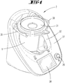
- FIG. 1 shows a food processor 2 according to the invention with a mixing vessel 1.
- the food processor 2 has a base unit 27 with a Rhakgefäßbefore, in which the mixing vessel 1 is inserted.
- a vessel bottom 3 is associated with a stirrer 4 (in FIG. 1 not shown), which is operable via a in the base unit 27 arranged, not shown electric drive.
- the mixing vessel 1 has a substantially vertically oriented handle 32, is pot-shaped with a circular cross-section and carries centrally arranged on the vessel bottom 3, the agitator 4.
- the vessel bottom 3 may be further associated with an electrical resistance heater.
- the base unit 27 of the food processor 2 further has a display 28 on which a selection menu, preparation instructions or the like can be displayed.
- a switch 29 is arranged, which is designed here as a rotary-key switch. About this one can the food processor 2 are turned on and off and on the other a selection are made, which is displayed for example on the display 28.
- the base unit 27 also has two locking rollers 30, which serve to lock the mixing vessel 1 with a lid 31.
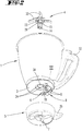
- FIG. 2 shows an exploded view of the mixing vessel 1 with removed agitator 4 and one of the vessel bottom 3 of the mixing vessel 1 removed foot 5.
- the agitator 4 is formed here as a knife bearing with a plurality of blades 33 which are rotatably connected to a stirrer shaft 14.
- the agitator shaft 14 is rotatably received in a bearing body 15 of the agitator 4, which can be passed through a bottom opening 34 of the vessel bottom 3 of the mixing vessel 1 in order to connect these rotatably with the vessel bottom 3.
- On the bearing body 15 a plurality of Fest GmbHsvorsprünge 23 are arranged, which can be guided by corresponding fixing means 24 of the bottom opening 34 of the vessel bottom 3.
- Each fixing means 24 is here a receiving area corresponding in its shape with a fixing projection 23. In the illustration, four such Fest einsvorsprünge 23 or fixing 24 are used.
- a plurality of electrical contacts 9 in the form of contact pins are arranged on the outside of the vessel bottom 3 in a connection region 8 which serves to connect to a corresponding connection region of the base device 27.
- the foot part 5 is as well as the mixing vessel 1 is substantially cup-shaped and serves as a receptacle for the vessel bottom 3 of the mixing vessel 1.
- the foot 5 provides a footing for the mixing vessel 1 ready to turn this example on a countertop, especially if the vessel bottom. 3 is heated by the heater.
- the electrical contacts 9 protrude into the interior of the foot part 5.
- the foot part 5 in turn can be connected in correspondence with the mixing vessel receptacle of the base unit 27 of the food processor 2. In this case, the electrical contacts 9 of the mixing vessel 1 come into contact with corresponding mating contacts of the base unit 27.
- the foot part 5 has a contact element 7, which acts in correctly mounted on the vessel bottom 3 state of the foot part 5 against the pawl 10 designed as a blocking element 6.
- the assembly of the foot part 5 on the bottom of the vessel 3 is carried out so that the foot part 5 is initially attached to the vessel bottom 3, that a predominantlyteilhandhabe 35 shows relative to a rotational axis 13 of the agitator 4 in a radial direction, which from a radial direction of the handle 32 of the mixing vessel 1 deviates. Then, the foot part 5 is rotated about the rotation axis 13, so that the proposedteilhandhabe 35 is pivoted to the handle 32. As a result of the rotation of the foot part 5, the contact element 7 arranged thereon is simultaneously displaced and comes into contact with the blocking element 6, ie the pawl 10.
- the contact element 7 presses the blocking element 6 against the restoring force of a spring element 36 from the electrical contact 9 away and out of the connection area 8, so that all electrical contacts 9 are freely accessible and can be connected when arranging the mixing vessel 1 in the base unit 27 with corresponding mating contacts. If the foot part 5 was not correctly mounted on the mixing vessel 1, the blocking element 6 protrudes into the connection region 8 and prevents the shape-corresponding connection between the mixing vessel 1 and the base unit 27th
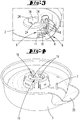
- FIG. 3 shows an enlarged section of the vessel bottom 3, in which the bottom opening 34 with the fixing means 24 and the connecting portion 8 with the electrical contacts 9, the blocking element 6 and the locking element 6 associated spring element 36 are arranged.
- FIG. 4 shows a perspective view in the foot part 5 of the mixing vessel 1.
- the foot part 5 has a contemplatteilö réelle 18, which is formed centrally on the foot part 5 and mounted on the bottom of the vessel 3 (and upright position of the mixing vessel 1) under the bottom opening 34 of Bottom of the vessel 3 is located, so that both the contemplatteilö réelle 18 and the bottom opening 34 are both arranged symmetrically to the rotation axis 13 and in the direction of the rotation axis 13 behind each other.
- the foot part opening 18 and the bottom opening 34 are substantially the same size, so that the bearing body 15 of the agitator 4 can be passed through both.
- the foot part opening 18 has fixing means 16, which correspond to corresponding bearing projections 17 of the agitator 4, in order to be able to clamp the agitator 4 to the bottom of the vessel 3 and the foot part 5.
- the fixing means 16 are formed here as fixing ramps 19.
- FIG. 4 shows further arranged on the foot part 5 contact element 7, which protrudes into the interior of the foot part 5, that this engages during assembly of the foot part 5 at the bottom of the vessel 3 in the connection region 8 of the vessel bottom 3 and optionally interacts there with the blocking element 6.
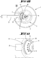
- FIG. 5 shows in detail the agitator 4 with the blades 33, which are rotatably connected to the agitator shaft 14.
- the agitator shaft 14 rotates about the rotation axis 13.
- a plurality of Fest GmbHsvorsprünge 23 are arranged, which serve for engagement in the fixing means 24 of the bottom opening 34 of the vessel bottom 3 of the mixing vessel 1.
- two bearing projections 17 are arranged below each Fest GmbHsvorsprungs 23, namely a bearing ramp 25 and a fixing projection 26. Based on the extension direction of the rotation axis 13 of the fixing projection 23 is arranged in a first plane 20.
- the bearing ramp 25 and the bearing ramps 25 are arranged in a second plane spaced therefrom 21 and the fixing projections 26 in a third plane 22.
- the Fest einsvorsprung 23 and the bearing ramp 25 go directly into each other, while the bearing ramp 25th and the fixing projection 26 are spaced apart in the direction of the axis of rotation 13, so that later in the arrangement of the agitator 4 and the foot part 5 at the bottom of the vessel 3, a corresponding fixing ramp 19 of the foot part 5 can be accommodated between them.
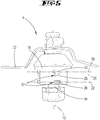
- FIG. 6 shows a arranged on the bottom of the vessel 3 state of the agitator 4.
- the fixing ramp 19 of the foot part 5 between the bearing ramp 25 and the fixing projection 26 of the bearing body 15 of the agitator 4 is performed.
- the fixing means 24 of the bottom opening 34 of the vessel bottom 3 and the fixing projections 23 of the bearing body 15 are engaged with each other, so that the fixing of the bearing body 15 on the base part 5 takes place at the same time fixing the vessel bottom 3.
- both the vessel bottom 3, and the agitator 4 and the foot part 5 are connected to each other, namely here via a crimp connection.
- FIG. 7 shows a bottom view of the mixing vessel 1 to the level of the vessel bottom 3.
- the fixing means 24 which are formed for receiving the Fest GmbHsvorsprünge 23 of the bearing body 15 of the agitator 4, and the connecting portion 8 of the vessel bottom 3, in which five electrical contacts 9 are formed.
- At one of the electrical contacts 9 is formed as a pawl 10 blocking element 6 at.
- the locking element 6 is pivotable about the pivot axis 11 and acted upon by the force of the spring element 36, which is designed here as a leg spring.
- the restoring force of the spring element 36 points in the direction of the electrical contact 9 against which the blocking element 6 rests in the blocking position.
- a release order is shown in dashed lines.
- This release position can reach the locking element 6 when overcoming the restoring force of the spring element 36.
- To overcome the restoring force is arranged on the foot part 5 contact element 7, which can press the locking element 6 from the voltage applied to the electrical contact 9 blocking position in the dashed line release position.
- FIG. 8 shows a bottom view of the mixing vessel 1 with disposed thereon foot part.
- FIG. 9 shows an enlarged section of it.
- the foot part 5 is located in a non-rotatably arranged on the mixing vessel 1 state.
- the carteteilhandhabe 35 and the handle 32 of the mixing vessel 1 are not yet aligned in the same radial direction relative to the axis of rotation 13 of the agitator 4.
- the blocking element 6 of the mixing vessel 1 Based on the blocking element 6 of the mixing vessel 1, this corresponds to the blocking position in which the blocking element 6 protrudes into the connecting region 8 of the mixing vessel, a part of the connecting region 8 is shaded by the foot part 5 and the electrical contacts 9 of the mixing vessel 1 as a result not with corresponding Mating contacts of the base unit 27 of the food processor 2 can be connected.
- the shape-corresponding connection between the mixing vessel 1 and the base unit 27 fails, firstly, because the foot part handle 35 protrudes beyond the handle 32 and, secondly, because of the contact of the blocking element 6 at the electrical contact 9, which prevents a shape-corresponding insertion of the electrical contacts 9 in the corresponding mating contacts of the base unit 27.
- FIG. 10 shows the contrast, the release position of the locking element 6, in which the locking element 6 is pushed out by means of the contact element 7 from the connecting portion 8.
- this release position are the handle 32 of the mixing vessel 1 and the predominantlyteilhandhabe 35 of the foot 5 in the same radial direction with respect to the axis of rotation 13 of the agitator 4.
- the restoring force of the spring element 36 can be overcome, so the abutment element 7 can completely remove the blocking element 6 from the connection area 8.
- the electrical contacts 9 are thus exposed and can be connected to the mating contacts of the base unit 27.
- FIG. 11 shows an enlarged section of the FIG. 10 ,
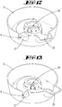
- FIG. 12 shows a perspective view of a foot part 5 according to a second embodiment.
- the foot part 5 on a locking element 6, which is designed as a locking bar 12.
- the locking bar 12 is semicircular in shape and mounted in the assembled state of the foot part 5 and bottom 3 in a plane parallel to the bottom of the vessel 3, namely about the axis of rotation 13 of the agitator 4.
- the locking bar 12 is connected to a spring element 36 with respect to an end portion, which is designed here for example as a helical spring.
- the spring element 36 is expanded in the direction of the restoring force, so that a spring element 36 opposite end portion of the locking bar 12 is displaced to a maximum extent in a blocking position.
- FIG. 13 shows a perspective view in the foot part 5 with retracted locking bolt 12.
- the locking bar 12 is retracted against the restoring force of the spring element 36. This position can only be achieved if the agitator 4 is clamped correctly on a vessel bottom 3 and a foot part 5 and the locking bar 12 is pushed back by a contact element 7 of the vessel bottom 3 in the release position.
- FIGS. 14 and 15 each show an underside of a mixing vessel 1 with foot part 5 arranged thereon
- FIG. 14 is in the mixing vessel 1, no agitator 4 is arranged, so that the foot part 5 is not fixed relative to the underside of the mixing vessel 1.
- an agitator 4 is mounted in the mixing vessel 1 and fixed to the foot part 5 and the vessel bottom 3 of the mixing vessel 1.
- the spring element 36 is expanded, so that the spring element 36 opposite end portion of the locking bar 12 is displaced into the blocking position and the foot part 5 relative to the vessel bottom 3 of the mixing vessel 1 so shifted that the foot part 5 covers part of the connecting portion 8 of the vessel bottom 3.
- the electrical contacts 9 are arranged so that they can not be connected to corresponding mating contacts of the base unit 27.
- a user of the food processor 2 leads the agitator 4 by one hand, the bottom opening 34 of the vessel bottom 3 and on the other hand, the intimidteilö réelle 18 of the foot 5.
Abstract
Description
- Die Erfindung betrifft ein Rührgefäß für eine elektromotorisch betriebene Küchenmaschine, mit einem Gefäßboden, einem durch den Gefäßboden in das Rührgefäß ragenden Rührwerk und einem außenseitig mit dem Gefäßboden verbindbaren Fußteil, welcher zur Fixierung des Rührwerks an dem Gefäßboden ausgebildet ist.
- Daneben betrifft die Erfindung eine elektromotorisch betriebene Küchenmaschine mit einem Basisgerät und einem mit dem Basisgerät verbindbaren Rührgefäß.
- Rührgefäße der in Rede stehenden Art sind bekannt, beispielsweise aus der
DE 10 2010 016 667 A1 oder derEP 2 875 762 B1 . - Die Rührgefäße finden insbesondere Einsatz in Verbindung mit einer elektromotorisch betriebenen Küchenmaschine, weiter insbesondere für den Haushaltsbereich. Zum Verrühren oder auch Zerkleinern von in das Rührgefäß eingebrachten Medien, insbesondere von eingebrachten Lebensmitteln, ist einem Gefäßboden des Rührgefäßes ein Rührwerk zugeordnet, beispielsweise in Form eines Messerwerkes. Eine Rührwerkwelle des Rührwerks durchsetzt den Gefäßboden, insbesondere zur Ausbildung eines frei nach unten über den Gefäßboden hinausragenden Kupplungsmitnehmers. Weiter ist diesbezüglich bekannt, das Rührgefäß in eine Rührgefäßaufnahme eines Basisgerätes der Küchenmaschine einzusetzen, in welcher das Rührgefäß mithilfe eines topfartigen Fußteils auf einer Aufstandfläche steht. Ein solcher Fußteil dient darüber hinaus in bekannter Weise zum Abstellen des Rührgefäßes auf einer Arbeitsfläche oder dergleichen nach Entnahme aus der Küchenmaschine.
- Des Weiteren ist es bekannt, das Rührwerk beispielsweise zu Reinigungszwecken und/oder zum Zwecke eines Austausches lösbar an dem Rührgefäß anzuordnen. Dazu kann das Rührwerk beispielsweise mittels einer bajonettartigen Befestigung an dem Gefäßboden angeordnet sein, dies weiter bevorzugt unter Einbindung und Festlegung des Fußteils an dem Rührgefäß.
- Das Rührwerk durchsetzt den Gefäßboden mit einem drehfest an dem Gefäßboden anordenbaren Lagerkörper, welcher einteilig oder auch mehrteilig ausgebildet sein kann. Der Lagerkörper ist wiederum durchsetzt von der Rührwerkwelle. Diesbezüglich ist weiter bekannt, zur Drehfestlegung an dem Gefäßboden wandungsaußenseitig des Lagerkörpers Vorsprünge vorzusehen, welche mit einer entsprechenden Kontur einer Öffnung des Gefäßbodens und/oder des Fußteils zusammenwirken.
- Bei den im Stand der Technik bekannten Rührgefäßen ist es grundsätzlich möglich, dass ein Nutzer des Rührgefäßes vergisst, das Rührwerk an dem Gefäßboden zu befestigen, und dadurch die im Gefäßboden ausgebildete Öffnung zu verschließen. Sofern er dann das Rührgefäß mit Lebensmitteln, insbesondere Flüssigkeiten, befüllt, kann es zu einem Austreten aus dem Rührgefäß und in das Basisgerät der Küchenmaschine kommen, was dort Schäden verursachen könnte.
- Im Hinblick auf den vorbeschriebenen Stand der Technik ist es daher Aufgabe der Erfindung, ein Rührgefäß der vorgenannten Art so weiterzubilden, dass ein versehentliches Einsetzen des Rührgefäßes ohne Rührwerk in die Küchenmaschine verhindert ist.
- Zur Lösung der vorgenannten Aufgabe wird vorgeschlagen, dass der Gefäßboden oder der Fußteil ein mit einer Federkraft eines Federelementes beaufschlagtes Sperrelement aufweist, welches mittels eines korrespondierenden Anlageelementes des Fußteils oder des Gefäßbodens von einer eine Fixierung des Rührwerks verhindernden Sperrstellung entgegen der Federkraft in eine eine Fixierung ermöglichende Freigabestellung verlagerbar ist.
- Durch diese erfindungsgemäße Ausgestaltung kommt es bei Abwesenheit eines Rührwerks an dem Gefäßboden auch nicht zu einer Fixierung des Fußteils an dem Gefäßboden. Somit bleibt der Fußteil relativ zu dem Gefäßboden verlagerbar und wird von dem Sperrelement bei Fixierungsversuchen des Nutzers stets in die Sperrstellung zurückgedrückt. In dieser Sperrstellung verhindert das Sperrelement ein Einsetzen des Rührgefäßes in die elektromotorisch betriebene Küchenmaschine, da das Rührgefäß nicht mehr in üblicher Art und Weise aufgenommen werden kann, sondern vielmehr beispielsweise keine Formkorrespondenz mehr zu der Rührgefäßaufnahme der Küchenmaschine aufweist oder eine Dimensionsänderung erleidet, welche beispielsweise ein Verriegeln des Rührgefäßes mit einem Deckel verhindert. Somit wird der Nutzer darauf aufmerksam gemacht, dass das Rührgefäß nicht ordnungsgemäß montiert ist, so dass entsprechend nachgebessert werden kann, bevor ein Schaden an der Küchenmaschine entsteht. Nur wenn das Rührwerk ordnungsgemäß an dem Gefäßboden befestigt ist, d. h. mittels des Fußteils an dem Gefäßboden fixiert, beispielsweise verklemmt, ist, ist auch der Fußteil drehfest mit dem Gefäßboden des Rührgefäßes verbunden, so dass beispielsweise das Anlageelement des Fußteils das Sperrelement des Gefäßbodens von der Sperrstellung in die Freigabestellung verlagert und somit eine Verbindung des Rührgefäßes mit der elektromotorisch betriebenen Küchenmaschine ermöglicht. Alternativ zu dem Gefäßboden kann auch der Fußteil ein mit einer Federkraft eines Federelementes beaufschlagtes Sperrelement aufweisen. In diesem Fall befindet sich das korrespondierende Anlageelement an dem Gefäßboden. Auch hierbei ist zur Verlagerung des Sperrelementes in die Freigabestellung wiederum eine ordnungsgemäße Fixierung des Rührwerks an dem Gefäßboden mittels des Fußteils notwendig.
- Das entweder an dem Gefäßboden oder dem Fußteil angeordnete Sperrelement kann beispielsweise ein separates Federelement aufweisen, beispielsweise eine Schraubenfeder, Schenkelfeder, Biegefeder, Torsionsfeder und dergleichen, oder selbst aus einem elastischen Material ausgebildet sein, so dass das Sperrelement selbst ein eine Federkraft bereitstellendes Federelement ist. Dabei kann das Sperrelement beispielsweis aus Metall gebildet sein, bevorzugt aus korrosionsbeständigem austenitischem Edelstahl oder aus martensitisch gehärtetem Stahl mit Korrosionsschutzbeschichtung. Weiter kann das Sperrelement auch aus Kunststoff hergestellt sein, beispielsweise aus einem Glasfaser-Kunststoff oder dergleichen.
- Das an dem Fußteil oder dem Gefäßboden angeordnete Anlageelement ist so angeordnet und ausgebildet, dass dieses in einen Verlagerungsweg des Sperrelementes hineinragt (bezogen auf eine an dem Rührgefäß angeordnete Stellung des Fußteils), welchen das Sperrelement von der Freigabestellung in die Sperrstellung, und umgekehrt, durchschreitet. Bei der Fixierung des Rührwerks und damit auch des Fußteils an dem Gefäßboden wird der Fußteil üblicherweise relativ zu dem Gefäßboden rotiert (um eine Rotationsachse des Rührwerks), wodurch das Anlageelement gegen das Sperrelement drückt. Das Anlageelement kann dabei ein an dem Gefäßboden bzw. dem Fußteil ausgebildeter Stift, Vorsprung, Wandungsteilbereich oder dergleichen sein.
- Des Weiteren wird vorgeschlagen, dass das Sperrelement so an dem Gefäßboden oder dem Fußteil angeordnet ist, dass dieses bezogen auf einen entspannten Zustand des Federelementes in einen für eine Verbindung des Rührgefäßes mit einer elektromotorisch betriebenen Küchenmaschine ausgebildeten Verbindungsbereich ragt und somit eine Verbindung verhindert. Das Sperrelement befindet sich in der Sperrstellung somit in einem Bereich, in welchem bei korrekter Verbindung des Rührgefäßes mit dem Basisgerät der Küchenmaschine korrespondierende Elemente ineinandergreifen, sich kontaktieren oder dergleichen. Sofern das Sperrelement in die Freigabestellung verlagert ist, können diese Elemente in üblicher Art und Weise zueinander geführt werden, so dass das Rührgefäß in die Küchenmaschine eingesetzt werden kann. Wenn das Sperrelement hingegen in diesen Verbindungsbereich hineinragt, stellt dieses ein Hindernis dar, welches die Verbindung zwischen dem Rührgefäß und der Rührgefäßaufnahme der Küchenmaschine verhindert. Insbesondere kann das Rührgefäß dadurch schräg in der Rührgefäßaufnahme stehen, eine zu große Bauhöhe aufweisen, welche eine Verriegelung des Rührgefäßes mit einem Deckel verhindert oder dergleichen.
- Insbesondere wird vorgeschlagen, dass der Verbindungsbereich elektrische Kontakte zur Verbindung mit entsprechenden Gegenkontakten einer elektromotorisch betriebenen Küchenmaschine aufweist. Sofern das Rührwerk nicht in den Gefäßboden eingesetzt ist, kann eine Fixierung zwischen dem Rührwerk und dem Gefäßboden und damit auch zwischen dem Fußteil und dem Gefäßboden nicht erreicht werden. Dies kann beispielsweise dazu führen, dass der Fußteil nicht in eine übliche Endstellung an dem Rührgefäß gebracht werden kann und der Verbindungsbereich des Gefäßbodens, welcher die elektrischen Kontakte aufweist, teilweise durch einen Teilbereich des Fußteils verdeckt bleibt, so dass die elektrischen Kontakte nicht in Verbindung mit Gegenkontakten der Küchenmaschine gebracht werden können. Gleichzeitig kann der angesprochene Teilbereich des Fußteils dadurch auf den Gegenkontakten aufliegen und somit eine gegenüber der ordnungsgemäß montierten Ausbildung des Rührgefäßes vergrößerte Höhe des Rührgefäßes oder auch eine Schrägstellung des Rührgefäßes in der Küchenmaschine bewirken. Diese Ausbildung eignet sich sowohl für Ausführungen, bei welchen das Sperrelement an dem Gefäßboden angeordnet ist, als auch für Ausführungen, bei welchen das Sperrelement an dem Fußteil angeordnet ist. In beiden Fällen kann eine Abdeckung zumindest eines der elektrischen Kontakte des Rührgefäßes innerhalb des Verbindungsbereiches erreicht werden.
- Des Weiteren wird vorgeschlagen, dass das Sperrelement eine an dem Gefäßboden schwenkbeweglich angeordnete Sperrklinke ist, welche um eine senkrecht zu dem Gefäßboden angeordnete Schwenkachse schwenkbar ist. Gemäß dieser Ausführungsform ist das Sperrelement an dem Gefäßboden des Rührgefäßes angeordnet. Das Sperrelement ist innerhalb einer Ebene verschwenkbar, welche parallel zu der Ebene des Gefäßbodens ausgerichtet ist. Dadurch kann die Sperrklinke über zumindest einen Teilbereich des Gefäßbodens, insbesondere des zuvor genannten Verbindungsbereiches, welcher für eine Verbindung mit der Küchenmaschine genutzt wird, verschwenkt werden. Es ergibt sich somit in besonders einfacher Art und Weise eine Verlagerung des Sperrelementes von der Sperrstellung in die Freigabestellung, und umgekehrt.
- Gemäß einer alternativen Ausführung wird vorgeschlagen, dass das Sperrelement ein an dem Fußteil schiebebeweglich angeordneter Sperrriegel ist, welcher bezogen auf einen verbundenen Zustand von Gefäßboden und Fußteil in einer zu dem Gefäßboden parallelen Ebene verschiebbar ist. Der Sperrriegel ist in der Freigabestellung so an einem Teilbereich des Fußteils angeordnet, dass der Sperrriegel nicht in einen Verbindungsbereich des Gefäßbodens ragt, welcher für eine ordnungsgemäße Verbindung des Rührgefäßes mit der elektromotorisch betriebenen Küchenmaschine benötigt wird. Durch die an dem Sperrriegel angreifende Federkraft wird der Sperrriegel bei fehlendem Kontakt des Sperrelementes zu einem Anlageelement des Gefäßbodens in der Sperrstellung gehalten, so dass bei fehlendem Rührwerk keine Fixierung zwischen dem Fußteil und dem Gefäßboden möglich ist und somit auch die Rückstellkraft des Federelementes nicht überwunden werden kann. Der Sperrriegel kann beispielsweise ein linienförmiger Sperrriegel sein, oder auch ein Sperrriegel, welcher nach der Art eines Kreisringsegmentes ausgebildet ist und um eine zentrale Öffnung des Fußteils rotierbar ist.
- Insbesondere kann vorgesehen sein, dass der Fußteil durch Rotation um eine Rotationsachse des Rührwerks an dem Rührwerk und/ oder dem Gefäßboden fixierbar ist. Bei dieser Ausgestaltung wird der Fußteil für eine Fixierung des Rührwerks an dem Gefäßboden (und damit auch für eine Fixierung des Fußteils an dem Gefäßboden) um die Rotationsachse rotiert. Dadurch kann auf besonders einfache Art und Weise ein an dem Fußteil angeordnetes Anlageelement gegen das Sperrelement bewegt werden bzw. ein an dem Fußteil angeordnetes Sperrelement gegen ein Anlageelement des Gefäßbodens bewegt werden. Wenn das Rührwerk nicht ordnungsgemäß in den Gefäßboden eingesetzt ist, kann das Fußteil nicht an dem Gefäßboden verspannt werden und das an dem Sperrelement angreifende Federelement bzw. das selbstfedernd ausgebildete Sperrelement drückt den Fußteil wieder in die Sperrstellung zurück, so dass ein Nutzer das Rührgefäß nicht korrekt in die Küchenmaschine einsetzen kann. Die Bewegung des Fußteils für die Fixierung des Rührwerkes an dem Gefäßboden erfolgt durch die Rotation um die Rotationsachse des Rührwerks in einer Ebene, welche der Schwenkebene der zuvor vorgeschlagenen Sperrklinke bzw. der Verschiebungsebene des zuvor vorgeschlagenen Sperrriegels entspricht. Es ergibt sich somit ein optimales Zusammenwirken im Sinne der Erfindung.
- Darüber hinaus kann vorgesehen sein, dass der Fußteil und ein eine Rührwerkwelle lagernder Lagerkörper des Rührwerks korrespondierende Fixierungsmittel aufweisen, welche für eine Fixierung des Rührwerks aneinander festlegbar sind. Dabei ist vorgesehen, dass die Fixierungsmittel nur aneinander festlegbar sind, wenn der Gefäßboden zwischen dem Rührwerk und dem Fußteil angeordnet ist, was regelmäßig dann der Fall ist, wenn das Rührwerk ordnungsgemäß in das Rührgefäß eingesetzt ist. Die Rührwerkwelle greift dann durch eine Bodenöffnung des Gefäßbodens hindurch, bis die Fixierungsmittel des Lagerkörpers in eine parallel zu dem Gefäßboden ausrichtete Ebene ragen, in welcher die korrespondierenden Fixierungsmittel des Fußteils angeordnet sind. Sodann können die Fixierungsmittel des Fußteils und des Lagerkörpers des Rührwerks aneinander festgelegt werden, beispielsweise durch Verrasten, Verquetschen oder dergleichen. Für eine Fixierung des Rührwerks an dem Gefäßboden ist es erforderlich, dass der Lagerkörper bzw. das Fußteil zumindest jeweils ein Fixierungsmittel aufweisen. Vorteilhaft ist jedoch, wenn diese jeweils eine Mehrzahl von Fixierungsmitteln aufweisen, welche beispielsweise in Umfangsrichtung des Lagerkörpers des Rührwerks angeordnet sind, besonders bevorzugt äquidistant.
- In diesem Zusammenhang wird insbesondere vorgeschlagen, dass der Lagerkörper des Rührwerks bezogen auf eine Rotationsachse des Rührwerks mindestens einen nach außen weisenden Lagervorsprung aufweist, und dass der Fußteil eine Fußteilöffnung zur Aufnahme des Lagerkörpers aufweist, wobei die Fußteilöffnung mindestens eine Fixierrampe zur Festlegung des Lagervorsprungs aufweist. Gemäß dieser Ausgestaltung weisen die korrespondierenden Fixierungsmittel zum einen einen an dem Lagerkörper angeordneten oder ausgebildeten Lagervorsprung und eine an dem Fußteil angeordnete oder ausgebildete Fixierrampe auf, welche insbesondere nach der Art einer Quetschverbindung aneinander festlegbar sind. Bezogen auf einen an dem Gefäßboden montierten Zustand des Rührwerks und des Fußteils liegen der Lagervorsprung und die Fixierrampe in Richtung der Rotationsachse betrachtet in unmittelbar nebeneinander angeordneten Ebenen, so dass der Lagervorsprung des Lagerkörpers bei einer Fixierbewegung des Fußteils an der Fixierrampe der Fußteilöffnung entlanggleitet, bis eine Endstellung erreicht ist, in welcher der Lagervorsprung maximal möglich mit der Fixierrampe verklemmt ist und das Rührwerk drehfest an dem Gefäßboden verklemmt ist.
- Insbesondere wird vorgeschlagen, dass der Lagerkörper eine Mehrzahl von Lagervorsprüngen aufweist, welche in eine Richtung parallel zu der Rotationsachse betrachtet in drei zueinander beabstandeten Ebenen angeordnet sind, wobei die Lagervorsprünge mindestens einen in einer ersten Ebene angeordneten Festsetzungsvorsprung zum Eingriff in ein korrespondierendes Fixierungsmittel des Gefäßbodens, mindestens eine in einer zweiten Ebene angeordnete Lagerrampe und mindestens einen in einer dritten Ebene angeordneten Fixierungsvorsprung aufweisen, wobei die Fixierrampe des Fußteils zwischen der Lagerrampe und dem Fixierungsvorsprung fixierbar ist. Der in der ersten Ebene angeordnete Festsetzungsvorsprung dient dabei zum Eingriff in ein korrespondierendes Fixierungsmittel des Gefäßbodens. Beispielsweise liegt der Festsetzungsvorsprung bei korrekt an dem Gefäßboden angeordnetem Rührwerk genau in der Ebene des Gefäßbodens. Beispielsweise ist das Fixierungsmittel des Gefäßbodens dabei eine in Bezug auf die Form des Festsetzungsvorsprungs korrespondierende Aussparung, in welche der Festsetzungsvorsprung eingreifen kann und somit eine Rotation des Rührwerks relativ zu dem Gefäßboden verhindert. In der zweiten Ebene, welche ausgehend von der ersten Ebene in das Innere des Fußteils ragt, befindet sich die Lagerrampe, welche zur Wechselwirkung mit einer korrespondierenden Fixierrampe der Fußteilöffnung ausgebildet ist. Die Lagerrampe ist nach der Art eines Sägezahns ausgebildet, dessen Flanke in eine Richtung zeigt, welche einer Rotationsrichtung des Fußteils entspricht, die zum Lösen der Fixierung zwischen dem Fußteil und dem Rührwerk erforderlich ist. Bei korrekter Anordnung von Rührgefäß, Rührwerk und Fußteil gelangen die Flanke der Lagerrampe und die Fixierrampe in Umfangsrichtung nicht aneinander, so dass eine Rotation des Fußteils sowohl in Sperrrichtung als auch in Freigaberichtung möglich ist. Nur für den Fall, dass sich der Gefäßboden nicht zwischen dem Fußteil und dem Rührwerk befindet, stoppt die Flanke der Lagerrampe die Rotation des Fußteils. Der in der dritten Ebene angeordnete Fixierungsvorsprung ragt in der korrekten Montagestellung ebenfalls in das Innere des Fußteils hinein und weist einen Abstand zu der in der zweiten Ebene angeordneten Lagerrampe auf, welche geeignet ist, die Fixierrampe der Fußteilöffnung aufzunehmen, wobei es aufgrund der Steigung der Fixierrampe der Fußteilöffnung bei fortschreitender Rotation des Fußteils um die Rotationsachse zu einem Verklemmen von Rührwerk, Fußteil und Gefäßboden kommt.
- Schließlich wird neben dem zuvor beschriebenen Rührgefäß ebenfalls eine elektromotorisch betriebene Küchenmaschine vorgeschlagen, welche ein Basisgerät und ein mit dem Basisgerät verbindbares Rührgefäß aufweist, das mit einem oder mehreren der zuvor in Bezug auf das Rührgefäß beschriebenen Merkmale ausgestattet ist. Die Merkmale und Vorzüge der elektromotorisch betriebenen Küchenmaschine ergeben sich dabei analog zu den in Bezug auf das Rührgefäß beschriebenen Merkmalen und Vorteilen.
- Im Folgenden wird die Erfindung anhand von Ausführungsbeispielen näher erläutert. Es zeigen:
- Fig. 1
- eine elektromotorisch betriebene Küchenmaschine mit einem darin eingesetzten Rührgefäß,
- Fig. 2
- eine Explosionsdarstellung des Rührgefäßes mit einem Rührwerk, einem Gefäßboden und einem Fußteil,
- Fig. 3
- eine vergrößerte Darstellung eines Teilbereiches des Gefäßbodens gemäß
Figur 2 , - Fig. 4
- den Fußteil in einer perspektivischen Ansicht von Innen gemäß einer ersten Ausführungsform,
- Fig. 5
- das Rührwerk in einer Detailansicht,
- Fig. 6
- das Rührwerk in einem an dem Gefäßboden montierten Zustand,
- Fig. 7
- eine perspektivische Ansicht des Gefäßbodens mit einem schwenkbaren Sperrelement,
- Fig. 8
- eine Unteransicht des Rührgefäßes mit Fußteil während einer Sperrstellung des Sperrelementes,
- Fig. 9
- einen vergrößerten Ausschnitt eines Verbindungsbereiches des Rührgefäßes,
- Fig. 10
- eine Unteransicht des Rührgefäßes mit dem Fußteil während einer Freigabestellung des Sperrelementes,
- Fig. 11
- eine vergrößerte Ansicht des Verbindungsbereiches,
- Fig. 12
- eine perspektivische Ansicht in einen Fußteil gemäß einer zweiten Ausführungsform mit einem Sperrelement in einer Sperrstellung,
- Fig. 13
- das Fußteil gemäß
Figur 12 mit dem Sperrelement in einer Freigabestellung, - Fig. 14
- eine Unteransicht eines Rührgefäßes mit dem Fußteil gemäß Figur 12 während einer Sperrstellung des Sperrelementes,
- Fig. 15
- das Rührgefäß mit dem Fußteil gemäß
Figur 13 während einer Freigabestellung des Sperrelementes. -
Figur 1 zeigt eine erfindungsgemäße Küchenmaschine 2 mit einem Rührgefäß 1. Die Küchenmaschine 2 weist ein Basisgerät 27 mit einer Rührgefäßaufnahme auf, in welche das Rührgefäß 1 eingesetzt ist. In dem Rührgefäß 1 ist einem Gefäßboden 3 ein Rührwerk 4 zugeordnet (inFigur 1 nicht dargestellt), welches über einen in dem Basisgerät 27 angeordneten, nicht dargestellten Elektroantrieb betreibbar ist. Das Rührgefäß 1 besitzt einen im Wesentlichen senkrecht ausgerichteten Griff 32, ist topfartig mit kreisrundem Querschnitt ausgebildet und trägt zentral an dem Gefäßboden 3 angeordnet das Rührwerk 4. Dem Gefäßboden 3 kann des Weiteren eine elektrische Widerstandsheizung zugeordnet sein. - Das Basisgerät 27 der Küchenmaschine 2 weist des Weiteren ein Display 28 auf, auf welchem ein Auswahlmenü, Zubereitungsanweisungen oder dergleichen angezeigt werden können. Daneben ist ein Schalter 29 angeordnet, welcher hier als Dreh-Tast-Schalter ausgebildet ist. Über diesen kann zum einen die Küchenmaschine 2 ein- und ausgeschaltet werden und zum anderen eine Auswahl getroffen werden, die beispielsweise auf dem Display 28 angezeigt wird. Das Basisgerät 27 verfügt zudem über zwei Verriegelungswalzen 30, welche zur Verriegelung des Rührgefäßes 1 mit einem Deckel 31 dienen.
-
Figur 2 zeigt eine Explosionsdarstellung des Rührgefäßes 1 mit entnommenem Rührwerk 4 und einem von dem Gefäßboden 3 des Rührgefäßes 1 abgenommenen Fußteil 5. Das Rührwerk 4 ist hier als Messerlager mit einer Mehrzahl von Messern 33 ausgebildet, welche drehfest mit einer Rührwerkwelle 14 verbunden sind. Die Rührwerkwelle 14 ist drehbar in einem Lagerkörper 15 des Rührwerks 4 aufgenommen, welcher durch eine Bodenöffnung 34 des Gefäßbodens 3 des Rührgefäßes 1 hindurchgeführt werden kann, um diesen drehfest mit dem Gefäßboden 3 zu verbinden. An dem Lagerkörper 15 sind mehrere Festsetzungsvorsprünge 23 angeordnet, welche durch entsprechende Fixierungsmittel 24 der Bodenöffnung 34 des Gefäßbodens 3 geführt werden können. Jedes Fixierungsmittel 24 ist hier ein in Bezug auf seine Form mit einem Festsetzungsvorsprung 23 korrespondierender Aufnahmebereich. In der Darstellung werden vier solcher Festsetzungsvorsprünge 23 bzw. Fixierungsmittel 24 eingesetzt. - An der Außenseite des Gefäßbodens 3 sind des Weiteren in einem Verbindungsbereich 8, welcher der Verbindung mit einem korrespondierenden Verbindungsbereich des Basisgerätes 27 dient, mehrere elektrische Kontakte 9 in Form von Kontaktstiften angeordnet. Dem Verbindungsbereich 8 zugeordnet ist ein Sperrelement 6, welches hier als eine um eine vertikale Schwenkachse 11 schwenkbare Sperrklinke 10 ausgebildet ist. Im dargestellten demontierten Zustand des Fußteils 5 liegt die Sperrklinke 10 an dem nächstliegenden elektrischen Kontakt 9 an und ragt somit in den Verbindungsbereich 8 hinein.
- Der Fußteil 5 ist wie auch das Rührgefäß 1 im Wesentlichen topfförmig ausgebildet und dient als Aufnahme für den Gefäßboden 3 des Rührgefäßes 1. Das Fußteil 5 stellt eine Standfläche für das Rührgefäß 1 bereit, um dieses beispielsweise auf einer Arbeitsplatte abzustellen, insbesondere wenn der Gefäßboden 3 mittels der Heizeinrichtung aufgeheizt ist. In einem an dem Gefäßboden 3 montierten Zustand des Fußteils 5 ragen die elektrischen Kontakte 9 in das Innere des Fußteils 5 hinein. Das Fußteil 5 wiederum kann formkorrespondierend mit der Rührgefäßaufnahme des Basisgerätes 27 der Küchenmaschine 2 verbunden werden. Dabei gelangen die elektrischen Kontakte 9 des Rührgefäßes 1 in Kontakt mit entsprechenden Gegenkontakten des Basisgerätes 27. Der Fußteil 5 weist ein Anlageelement 7 auf, welches im korrekt an dem Gefäßboden 3 montierten Zustand des Fußteils 5 gegen das als Sperrklinke 10 ausgebildete Sperrelement 6 wirkt.
- Die Montage des Fußteils 5 an dem Gefäßboden 3 erfolgt so, dass das Fußteil 5 zunächst so an den Gefäßboden 3 angesetzt wird, dass eine Fußteilhandhabe 35 bezogen auf eine Rotationsachse 13 des Rührwerks 4 in eine radiale Richtung zeigt, welche von einer radialen Richtung des Griffes 32 des Rührgefäßes 1 abweicht. Sodann wird der Fußteil 5 um die Rotationsachse 13 rotiert, so dass die Fußteilhandhabe 35 auf den Griff 32 zugeschwenkt wird. Durch die Rotation des Fußteils 5 wird gleichzeitig auch das daran angeordnete Anlageelement 7 verlagert und gelangt in Kontakt mit dem Sperrelement 6, d. h. hier der Sperrklinke 10. Bei fortschreitender Rotation drückt das Anlageelement 7 das Sperrelement 6 entgegen der Rückstellkraft eines Federelementes 36 von dem elektrischen Kontakt 9 weg und aus dem Verbindungsbereich 8 heraus, so dass alle elektrischen Kontakte 9 frei zugänglich sind und bei Anordnen des Rührgefäßes 1 in dem Basisgerät 27 mit entsprechenden Gegenkontakten verbunden werden können. Sofern der Fußteil 5 nicht korrekt an dem Rührgefäß 1 montiert wurde, ragt das Sperrelement 6 in den Verbindungsbereich 8 hinein und hindert die formkorrespondierende Verbindung zwischen dem Rührgefäß 1 und dem Basisgerät 27.
-
Figur 3 zeigt einen vergrößerten Ausschnitt des Gefäßbodens 3, in welchem die Bodenöffnung 34 mit den Fixierungsmitteln 24 und der Verbindungsbereich 8 mit den elektrischen Kontakten 9, dem Sperrelement 6 und dem dem Sperrelement 6 zugeordneten Federelement 36 angeordnet sind. -
Figur 4 zeigt eine perspektivische Ansicht in den Fußteil 5 des Rührgefäßes 1. Der Fußteil 5 weist eine Fußteilöffnung 18 auf, welche zentral an dem Fußteil 5 ausgebildet ist und bei an dem Gefäßboden 3 montiertem Zustand (und aufrechter Stellung des Rührgefäßes 1) unter der Bodenöffnung 34 des Gefäßbodens 3 liegt, so dass sowohl die Fußteilöffnung 18 als auch die Bodenöffnung 34 beide symmetrisch zu der Rotationsachse 13 angeordnet sind und in Richtung der Rotationsachse 13 hintereinanderliegen. Die Fußteilöffnung 18 und die Bodenöffnung 34 sind im Wesentlichen gleich groß, so dass der Lagerkörper 15 des Rührwerks 4 durch beide hindurchgeführt werden kann. Die Fußteilöffnung 18 weist Fixierungsmittel 16 auf, welche zu entsprechenden Lagervorsprüngen 17 des Rührwerks 4 korrespondieren, um das Rührwerk 4 an dem Gefäßboden 3 und dem Fußteil 5 verklemmen zu können. Die Fixierungsmittel 16 sind hier als Fixierrampen 19 ausgebildet.Figur 4 zeigt des Weiteren das an dem Fußteil 5 angeordnete Anlageelement 7, welches so in das Innere des Fußteils 5 hineinragt, dass dieses bei Montage des Fußteils 5 an dem Gefäßboden 3 in den Verbindungsbereich 8 des Gefäßbodens 3 hineingreift und dort gegebenenfalls mit dem Sperrelement 6 wechselwirkt. -
Figur 5 zeigt im Detail das Rührwerk 4 mit den Messern 33, welche drehfest mit der Rührwerkwelle 14 verbunden sind. Die Rührwerkwelle 14 rotiert um die Rotationsachse 13. An dem Lagerkörper 15, welcher drehfest mit dem Gefäßboden 3 verbunden werden kann, sind mehrere Festsetzungsvorsprünge 23 angeordnet, welche zum Eingriff in die Fixierungsmittel 24 der Bodenöffnung 34 des Gefäßbodens 3 des Rührgefäßes 1 dienen. In gleicher radialer Richtung - bezogen auf die Rotationsachse 13 - sind unterhalb jedes Festsetzungsvorsprungs 23 je zwei Lagervorsprünge 17 angeordnet, nämlich eine Lagerrampe 25 und ein Fixierungsvorsprung 26. Bezogen auf die Erstreckungsrichtung der Rotationsachse 13 ist der Festsetzungsvorsprung 23 in einer ersten Ebene 20 angeordnet. Die Lagerrampe 25 bzw. die Lagerrampen 25 (in Umfangsrichtung des Lagerkörpers 15) sind in einer dazu beabstandeten zweiten Ebene 21 angeordnet und die Fixierungsvorsprünge 26 in einer dritten Ebene 22. Der Festsetzungsvorsprung 23 und die Lagerrampe 25 gehen unmittelbar ineinander über, während die Lagerrampe 25 und der Fixierungsvorsprung 26 in Richtung der Rotationsachse 13 zueinander beabstandet sind, so dass später bei Anordnung des Rührwerks 4 und des Fußteils 5 an dem Gefäßboden 3 eine entsprechende Fixierrampe 19 des Fußteils 5 zwischen diesen aufgenommen werden kann. -
Figur 6 zeigt einen an dem Gefäßboden 3 angeordneten Zustand des Rührwerks 4. Hier ist die Fixierrampe 19 des Fußteils 5 zwischen die Lagerrampe 25 und den Fixierungsvorsprung 26 des Lagerkörpers 15 des Rührwerks 4 geführt. Gleichzeitig stehen auch die Fixierungsmittel 24 der Bodenöffnung 34 des Gefäßbodens 3 und die Festsetzungsvorsprünge 23 des Lagerkörpers 15 in Eingriff miteinander, so dass die Festsetzung des Lagerkörpers 15 an dem Fußteil 5 gleichzeitig unter Festsetzung des Gefäßbodens 3 erfolgt. Somit sind sowohl der Gefäßboden 3, als auch das Rührwerk 4 und der Fußteil 5 miteinander verbunden, nämlich hier über eine Quetschverbindung. -
Figur 7 zeigt eine Unteransicht des Rührgefäßes 1 auf die Ebene des Gefäßbodens 3. Zu erkennen sind die Bodenöffnung 34 mit den Fixierungsmitteln 24, welche zur Aufnahme der Festsetzungsvorsprünge 23 des Lagerkörpers 15 des Rührwerks 4 ausgebildet sind, sowie der Verbindungsbereich 8 des Gefäßbodens 3, in welchem fünf elektrische Kontakte 9 ausgebildet sind. An einem der elektrischen Kontakte 9 liegt das als Sperrklinke 10 ausgebildete Sperrelement 6 an. Das Sperrelement 6 ist um die Schwenkachse 11 schwenkbar und mit der Kraft des Federelementes 36 beaufschlagt, welches hier als Schenkelfeder ausgebildet ist. Die Rückstellkraft des Federelementes 36 weist in Richtung des elektrischen Kontaktes 9, an welchem das Sperrelement 6 in der Sperrstellung anliegt. Demgegenüber ist eine Freigabestellung gestrichelt gezeichnet. Diese Freigabestellung kann das Sperrelement 6 bei Überwindung der Rückstellkraft des Federelementes 36 erreichen. Zum Überwinden der Rückstellkraft dient das an dem Fußteil 5 angeordnete Anlageelement 7, welches das Sperrelement 6 von der an dem elektrischen Kontakt 9 anliegenden Sperrstellung in die gestrichelt gezeichnete Freigabestellung drücken kann. -
Figur 8 zeigt eine Unteransicht des Rührgefäßes 1 mit daran angeordnetem Fußteil 5.Figur 9 zeigt einen vergrößerten Ausschnitt daraus. Der Fußteil 5 befindet sich in einem noch nicht drehfest an dem Rührgefäß 1 angeordneten Zustand. Dabei sind die Fußteilhandhabe 35 und der Griff 32 des Rührgefäßes 1 noch nicht in derselben radialen Richtung relativ zu der Rotationsachse 13 des Rührwerks 4 ausgerichtet. Bezogen auf das Sperrelement 6 des Rührgefäßes 1 entspricht dies der Sperrstellung, in welcher das Sperrelement 6 in den Verbindungsbereich 8 des Rührgefäßes hineinragt, ein Teil des Verbindungsbereiches 8 durch den Fußteil 5 abgeschattet ist und die elektrischen Kontakte 9 des Rührgefäßes 1 infolge dessen nicht mit entsprechenden Gegenkontakten des Basisgerätes 27 der Küchenmaschine 2 verbunden werden können. Sofern ein Nutzer das Rührgefäß 1 in diesem Zustand mit dem Basisgerät 27 zu verbinden sucht, scheitert die formkorrespondierende Verbindung zwischen dem Rührgefäß 1 und dem Basisgerät 27 zum einen an dem Herausstehen der Fußteilhandhabe 35 über den Griff 32 hinaus und zum anderen an der Anlage des Sperrelementes 6 an dem elektrischen Kontakt 9, was ein formkorrespondierendes Einbringen der elektrischen Kontakte 9 in die entsprechenden Gegenkontakte des Basisgerätes 27 verhindert. -
Figur 10 zeigt demgegenüber die Freigabestellung des Sperrelementes 6, in welcher das Sperrelement 6 mittels des Anlageelementes 7 aus dem Verbindungsbereich 8 herausgedrückt ist. In dieser Freigabestellung liegen der Griff 32 des Rührgefäßes 1 und die Fußteilhandhabe 35 des Fußteils 5 in derselben radialen Richtung bezogen auf die Rotationsachse 13 des Rührwerkes 4. Durch die bei der Rotation des Fußteils 5 aufgewendete Kraft kann die Rückstellkraft des Federelementes 36 überwunden werden, so dass das Anlageelement 7 das Sperrelement 6 vollständig aus dem Verbindungsbereich 8 entfernen kann. Die elektrischen Kontakte 9 liegen somit frei und können mit den Gegenkontakten des Basisgerätes 27 verbunden werden.Figur 11 zeigt einen vergrößerten Ausschnitt derFigur 10 . -
Figur 12 zeigt eine perspektivische Ansicht in ein Fußteil 5 gemäß einer zweiten Ausführungsform. Hier weist der Fußteil 5 ein Sperrelement 6 auf, welches als Sperrriegel 12 ausgebildet ist. Der Sperrriegel 12 ist halbkreisförmig ausgebildet und im gezeigten montierten Zustand von Fußteil 5 und Gefäßboden 3 in einer Ebene parallel zu dem Gefäßboden 3 verlagerbar, nämlich um die Rotationsachse 13 des Rührwerks 4. Der Sperrriegel 12 ist bezogen auf einen Endbereich mit einem Federelement 36 verbunden, welches hier beispielsweise als Schraubenfeder ausgebildet ist. In der inFigur 12 dargestellten Situation ist das Federelement 36 in Richtung der Rückstellkraft expandiert, so dass ein dem Federelement 36 gegenüberliegender Endbereich des Sperrriegels 12 maximal weit in eine Sperrstellung verlagert ist. -
Figur 13 zeigt eine perspektivische Ansicht in den Fußteil 5 bei eingefahrenem Sperrriegel 12. Dabei ist der Sperrriegel 12 gegen die Rückstellkraft des Federelementes 36 eingefahren. Diese Stellung kann nur erreicht werden, wenn das Rührwerk 4 korrekt an einem Gefäßboden 3 und einem Fußteil 5 verspannt ist und der Sperrriegel 12 von einem Anlageelement 7 des Gefäßbodens 3 in die Freigabestellung zurückgedrückt wird. - Die
Figuren 14 und 15 zeigen jeweils eine Unterseite eines Rührgefäßes 1 mit daran angeordnetem Fußteil 5. InFigur 14 ist in dem Rührgefäß 1 kein Rührwerk 4 angeordnet, so dass der Fußteil 5 nicht gegenüber der Unterseite des Rührgefäßes 1 fixiert ist. InFigur 15 ist ein Rührwerk 4 in dem Rührgefäß 1 montiert und an dem Fußteil 5 sowie dem Gefäßboden 3 des Rührgefäßes 1 fixiert. - Gemäß
Figur 14 ist das Federelement 36 expandiert, so dass der dem Federelement 36 gegenüberliegende Endbereich des Sperrriegels 12 in die Sperrstellung verlagert ist und den Fußteil 5 gegenüber dem Gefäßboden 3 des Rührgefäßes 1 so verlagert, dass der Fußteil 5 einen Teil des Verbindungsbereiches 8 des Gefäßbodens 3 verdeckt. In dem Verbindungsbereich 8 sind die elektrischen Kontakte 9 angeordnet, so dass diese nicht mit entsprechenden Gegenkontakten des Basisgerätes 27 verbunden werden können. Um nun die Verbindung der elektrischen Kontakte 9 mit den Gegenkontakten des Basisgerätes 27 zu ermöglichen, ist es erforderlich, den Fußteil 5 so zu verlagern, dass die inFigur 15 dargestellte Stellung erreicht ist. Dazu führt ein Nutzer der Küchenmaschine 2 das Rührwerk 4 durch einerseits die Bodenöffnung 34 des Gefäßbodens 3 und andererseits die Fußteilöffnung 18 des Fußteils 5. Sodann kann der Fußteil 5 gegenüber dem Gefäßboden 3 und dem Fußteil 5 verspannt werden, so dass die Rückstellkraft des Federelementes 36 überwunden werden kann und der Verbindungsbereich 8 freigelegt wird. Das Federelement 36 drückt dabei gegen das korrespondierende Anlageelement 7 des Gefäßbodens 3 und kann somit unter Freigabe des Verbindungsbereiches 8 komprimiert werden. Im Übrigen gelten die Ausführungen, die in Bezug auf die erste Ausführungsform derFiguren 8 bis 11 gemacht wurden analog.Liste der Bezugszeichen 1 Rührgefäß 26 Fixierungsvorsprung 2 Küchenmaschine 27 Basisgerät 3 Gefäßboden 28 Display 4 Rührwerk 29 Schalter 5 Fußteil 30 Verriegelungswalze 6 Sperrelement 31 Deckel 7 Anlageelement 32 Griff 8 Verbindungsbereich 33 Messer 9 Elektrischer Kontakt 34 Bodenöffnung 10 Sperrklinke 35 Fußteilhandhabe 11 Schwenkachse 36 Federelement 12 Sperrriegel 13 Rotationsachse 14 Rührwerkwelle 15 Lagerkörper 16 Fixierungsmittel 17 Lagervorsprung 18 Fußteilöffnung 19 Fixierrampe 20 Ebene 21 Ebene 22 Ebene 23 Festsetzungsvorsprung 24 Fixierungsmittel 25 Lagerrampe
Claims (10)
- Rührgefäß (1) für eine elektromotorisch betriebene Küchenmaschine (2), mit einem Gefäßboden (3), einem durch den Gefäßboden (3) in das Rührgefäß (1) ragenden Rührwerk (4) und einem außenseitig mit dem Gefäßboden (3) verbindbaren Fußteil (5), welcher zur Fixierung des Rührwerks (4) an dem Gefäßboden (3) ausgebildet ist, dadurch gekennzeichnet, dass der Gefäßboden (3) oder der Fußteil (5) ein mit einer Federkraft eines Federelementes (36) beaufschlagtes Sperrelement (6) aufweist, welches mittels eines korrespondierenden Anlageelementes (7) des Fußteils (5) oder des Gefäßbodens (3) von einer eine Fixierung des Rührwerks (4) verhindernden Sperrstellung entgegen der Federkraft in eine eine Fixierung ermöglichende Freigabestellung verlagerbar ist.
- Rührgefäß (1) nach Anspruch 1, dadurch gekennzeichnet, dass das Sperrelement (6) so an dem Gefäßboden (3) oder dem Fußteil (5) angeordnet ist, dass dieses bezogen auf einen entspannten Zustand des Federelementes (36) in einen für eine Verbindung des Rührgefäßes (1) mit einer elektromotorisch betriebenen Küchenmaschine (2) ausgebildeten Verbindungsbereich (8) ragt und somit eine Verbindung verhindert.
- Rührgefäß (1) nach Anspruch 2, dadurch gekennzeichnet, dass der Verbindungsbereich (8) elektrische Kontakte (9) zur Verbindung mit entsprechenden Gegenkontakten einer elektromotorisch betriebenen Küchenmaschine (2) aufweist.
- Rührgefäß (1) nach einem der Ansprüche 1 bis 3, dadurch gekennzeichnet, dass das Sperrelement (6) eine an dem Gefäßboden (3) schwenkbeweglich angeordnete Sperrklinke (10) ist, welche um eine senkrecht zu dem Gefäßboden (3) angeordnete Schwenkachse (11) schwenkbar ist.
- Rührgefäß (1) nach einem der Ansprüche 1 bis 3, dadurch gekennzeichnet, dass das Sperrelement (6) ein an dem Fußteil (5) schiebebeweglich angeordneter Sperrriegel (12) ist, welcher bezogen auf einen verbundenen Zustand von Gefäßboden (3) und Fußteil (5) in einer zu dem Gefäßboden (3) parallelen Ebene verschiebbar ist.
- Rührgefäß (1) nach einem der vorhergehenden Ansprüche, dadurch gekennzeichnet, dass der Fußteil (5) durch Rotation um eine Rotationsachse (13) des Rührwerks (4) an dem Rührwerk (4) und/ oder dem Gefäßboden (3) fixierbar ist.
- Rührgefäß (1) nach einem der vorhergehenden Ansprüche, dadurch gekennzeichnet, dass der Fußteil (5) und ein eine Rührwerkwelle (14) lagernder Lagerkörper (15) des Rührwerks (4) korrespondierende Fixierungsmittel (16) aufweisen, welche für eine Fixierung des Rührwerks (4) aneinander festlegbar sind.
- Rührgefäß (1) nach Anspruch 7, dadurch gekennzeichnet, dass der Lagerkörper (15) des Rührwerks (4) bezogen auf eine Rotationsachse (13) des Rührwerks (4) mindestens einen nach außen weisenden Lagervorsprung (17) aufweist, und dass der Fußteil (5) eine Fußteilöffnung (18) zur Aufnahme des Lagerkörpers (15) aufweist, wobei die Fußteilöffnung (18) mindestens eine Fixierrampe (19) zur Festlegung des Lagervorsprungs (17) aufweist.
- Rührgefäß (1) nach Anspruch 8, dadurch gekennzeichnet, dass der Lagerkörper (15) eine Mehrzahl von Lagervorsprüngen (17) aufweist, welche in eine Richtung parallel zu der Rotationsachse (13) betrachtet in drei zueinander beabstandeten Ebenen (20, 21, 22) angeordnet sind, wobei die Lagervorsprünge (17) aufweisen: mindestens einen in einer ersten Ebene (20) angeordneten Festsetzungsvorsprung (23) zum Eingriff in ein korrespondierendes Fixierungsmittel (24) des Gefäßbodens (3), mindestens eine in einer zweiten Ebene (21) angeordnete Lagerrampe (25) und mindestens einen in einer dritten Ebene (22) angeordneten Fixierungsvorsprung (26), wobei die Fixierrampe (19) des Fußteils (5) zwischen der Lagerrampe (25) und dem Fixierungsvorsprung (26) fixierbar ist.
- Elektromotorisch betriebene Küchenmaschine (2) mit einem Basisgerät (27) und einem mit dem Basisgerät (27) verbindbaren Rührgefäß (1), dadurch gekennzeichnet, dass das Rührgefäß (1) nach einem der vorhergehenden Ansprüche ausgebildet ist.
Priority Applications (1)
| Application Number | Priority Date | Filing Date | Title |
|---|---|---|---|
| PL17189150T PL3292806T3 (pl) | 2016-09-07 | 2017-09-04 | Zbiornik mieszający napędzanej elektromotorycznie maszyny kuchennej |
Applications Claiming Priority (1)
| Application Number | Priority Date | Filing Date | Title |
|---|---|---|---|
| DE102016116757.6A DE102016116757A1 (de) | 2016-09-07 | 2016-09-07 | Rührgefäß für eine elektromotorisch betriebene Küchenmaschine |
Publications (2)
| Publication Number | Publication Date |
|---|---|
| EP3292806A1 true EP3292806A1 (de) | 2018-03-14 |
| EP3292806B1 EP3292806B1 (de) | 2019-10-30 |
Family
ID=59772491
Family Applications (1)
| Application Number | Title | Priority Date | Filing Date |
|---|---|---|---|
| EP17189150.0A Active EP3292806B1 (de) | 2016-09-07 | 2017-09-04 | Rührgefäss für eine elektromotorisch betriebene küchenmaschine |
Country Status (10)
| Country | Link |
|---|---|
| US (1) | US10383483B2 (de) |
| EP (1) | EP3292806B1 (de) |
| CN (1) | CN107788875B (de) |
| AU (1) | AU2017225035B2 (de) |
| DE (1) | DE102016116757A1 (de) |
| ES (1) | ES2757959T3 (de) |
| MX (1) | MX2017011416A (de) |
| PL (1) | PL3292806T3 (de) |
| PT (1) | PT3292806T (de) |
| TW (1) | TW201811244A (de) |
Cited By (1)
| Publication number | Priority date | Publication date | Assignee | Title |
|---|---|---|---|---|
| WO2020124138A1 (en) | 2018-12-21 | 2020-06-25 | Breville Pty Limited | A kitchen device |
Families Citing this family (5)
| Publication number | Priority date | Publication date | Assignee | Title |
|---|---|---|---|---|
| EP3858199A1 (de) * | 2020-01-30 | 2021-08-04 | Vorwerk & Co. Interholding GmbH | System mit küchengeräten für ein koordiniertes kochen und verfahren |
| EP3875007A1 (de) * | 2020-03-06 | 2021-09-08 | Vorwerk & Co. Interholding GmbH | Zubereitungsgefäss zum verbinden mit einem aufnahmebereich eines basisgerätes einer küchenmaschine |
| DE102020123218A1 (de) | 2020-09-04 | 2022-03-10 | Vorwerk & Co. Interholding Gesellschaft mit beschränkter Haftung | Elektrisch betriebenes Küchengerät mit einer elektrischen Schnittstelle für ein Zubereitungsgefäß |
| DE102021206293A1 (de) | 2021-06-18 | 2022-12-22 | Vorwerk & Co. Interholding Gesellschaft mit beschränkter Haftung | Elektrisches Haushaltsgerät mit Berührschutz für elektrische Kontakte |
| ES1286359Y (es) | 2021-12-14 | 2022-05-05 | Taurus Res And Development Slu | Recipiente de mezcla con agitador para procesador de alimentos automatico |
Citations (4)
| Publication number | Priority date | Publication date | Assignee | Title |
|---|---|---|---|---|
| GB1422701A (en) * | 1972-01-11 | 1976-01-28 | Ronson Corp | Domestic blenders |
| FR2908619A1 (fr) * | 2006-11-21 | 2008-05-23 | Seb Sa | Appareil de preparation culinaire muni d'un dispositif de securite. |
| DE102010016667A1 (de) | 2010-04-28 | 2011-11-03 | Vorwerk & Co. Interholding Gmbh | Rührgefäß für eine Küchenmaschine |
| EP2875762A1 (de) * | 2013-11-22 | 2015-05-27 | Vorwerk & Co. Interholding GmbH | Rührgefäß für eine Küchenmaschine |
Family Cites Families (6)
| Publication number | Priority date | Publication date | Assignee | Title |
|---|---|---|---|---|
| EP1045658B1 (de) * | 1998-10-23 | 2003-11-26 | Koninklijke Philips Electronics N.V. | Zusatzgerät mit sicherheitsglied für küchenmaschinen |
| JP3739345B2 (ja) * | 2002-08-23 | 2006-01-25 | ツインバード工業株式会社 | 調理機 |
| US7220049B2 (en) * | 2004-08-09 | 2007-05-22 | Ming-Tsung Lee | Blender with a safe starting function |
| DE202011100183U1 (de) * | 2011-05-03 | 2012-08-06 | Geka Gmbh | Kosmetikeinheit mit blockierbarem Rastverschluss |
| DE102011054639A1 (de) * | 2011-10-20 | 2013-04-25 | Krones Ag | Führungsvorrichtung für Behälter, insbesondere für Glasflaschen, Kunststoffflaschen, Dosen, Getränkekartons und/oder Kartonagen |
| DE102013106565A1 (de) * | 2013-06-24 | 2014-12-24 | Vorwerk & Co. Interholding Gmbh | Einbauteil, beispielsweise einer Küchenmaschine sowie Küchenmaschine mit einem Rührgefäß |
-
2016
- 2016-09-07 DE DE102016116757.6A patent/DE102016116757A1/de not_active Withdrawn
-
2017
- 2017-08-30 CN CN201710761421.XA patent/CN107788875B/zh active Active
- 2017-09-04 ES ES17189150T patent/ES2757959T3/es active Active
- 2017-09-04 PT PT171891500T patent/PT3292806T/pt unknown
- 2017-09-04 PL PL17189150T patent/PL3292806T3/pl unknown
- 2017-09-04 TW TW106130159A patent/TW201811244A/zh unknown
- 2017-09-04 EP EP17189150.0A patent/EP3292806B1/de active Active
- 2017-09-06 US US15/696,788 patent/US10383483B2/en active Active
- 2017-09-06 MX MX2017011416A patent/MX2017011416A/es unknown
- 2017-09-06 AU AU2017225035A patent/AU2017225035B2/en active Active
Patent Citations (5)
| Publication number | Priority date | Publication date | Assignee | Title |
|---|---|---|---|---|
| GB1422701A (en) * | 1972-01-11 | 1976-01-28 | Ronson Corp | Domestic blenders |
| FR2908619A1 (fr) * | 2006-11-21 | 2008-05-23 | Seb Sa | Appareil de preparation culinaire muni d'un dispositif de securite. |
| DE102010016667A1 (de) | 2010-04-28 | 2011-11-03 | Vorwerk & Co. Interholding Gmbh | Rührgefäß für eine Küchenmaschine |
| EP2875762A1 (de) * | 2013-11-22 | 2015-05-27 | Vorwerk & Co. Interholding GmbH | Rührgefäß für eine Küchenmaschine |
| EP2875762B1 (de) | 2013-11-22 | 2016-03-02 | Vorwerk & Co. Interholding GmbH | Rührgefäß für eine Küchenmaschine |
Cited By (2)
| Publication number | Priority date | Publication date | Assignee | Title |
|---|---|---|---|---|
| WO2020124138A1 (en) | 2018-12-21 | 2020-06-25 | Breville Pty Limited | A kitchen device |
| EP3897321A4 (de) * | 2018-12-21 | 2022-09-07 | Breville Pty Limited | Küchenvorrichtung |
Also Published As
| Publication number | Publication date |
|---|---|
| DE102016116757A1 (de) | 2018-03-08 |
| PT3292806T (pt) | 2019-12-03 |
| AU2017225035A1 (en) | 2018-03-22 |
| CN107788875B (zh) | 2022-02-22 |
| US10383483B2 (en) | 2019-08-20 |
| EP3292806B1 (de) | 2019-10-30 |
| AU2017225035B2 (en) | 2022-09-01 |
| TW201811244A (zh) | 2018-04-01 |
| US20180064288A1 (en) | 2018-03-08 |
| PL3292806T3 (pl) | 2020-05-18 |
| ES2757959T3 (es) | 2020-04-30 |
| CN107788875A (zh) | 2018-03-13 |
| MX2017011416A (es) | 2018-09-21 |
Similar Documents
| Publication | Publication Date | Title |
|---|---|---|
| EP3292806B1 (de) | Rührgefäss für eine elektromotorisch betriebene küchenmaschine | |
| DE2022375A1 (de) | Kuechengeraet | |
| DE2301577A1 (de) | Mischzerkleinerer | |
| DE102006059078A1 (de) | Elektrogerät mit aufgerastetem drehbarem Bedienungselement | |
| EP2875762A1 (de) | Rührgefäß für eine Küchenmaschine | |
| EP2978349B1 (de) | Bearbeitungsaufsatz mit eingriffschutz | |
| DE3211810A1 (de) | Halter fuer eine elektrische zahnbuerste | |
| DE2232470B2 (de) | Handrühr- und Mischgerät | |
| DE102018119811A1 (de) | Rührwerklager für eine elektromotorisch betriebene Küchenmaschine | |
| DE102011052745A1 (de) | Elektrisch betriebene Küchenmaschine | |
| EP3469969A1 (de) | Elektromotorisch betriebene küchenmaschine sowie rührgefäss und rührwerk dafür | |
| EP3287056B1 (de) | Multifunktionale kupplungseinrichtung für eine küchenmaschine | |
| EP3530160B1 (de) | Speisenzubereitungsvorrichtung mit verriegelung | |
| EP3287057B1 (de) | Verriegelungsvorrichtung zur aufnahme einer bearbeitungseinheit | |
| DE2930533A1 (de) | Haushaltsgeraet, insbesondere mehrzweck-kuechenmaschine fuer verschiedene arbeitsgeraete | |
| DE202019100726U1 (de) | Behälter mit universell einsetzbarer nicht sichtbarer Griffbefestigung zur Verwendung mit Haushaltsgeräten | |
| EP3771383A1 (de) | Kupplungswelle, rotationswerkzeugeinrichtung und gefäss-werkzeug-kombination für eine küchenmaschine sowie küchenmaschine | |
| DE3105185C2 (de) | ||
| DE60010851T2 (de) | Haushaltsgerät mit einem federgelagerten rührwerkansatz | |
| EP3569116B1 (de) | Speisenzubereitungsvorrichtung mit lösbarem werkzeug | |
| DE102018207505B4 (de) | Küchengerät-Basisteil und Küchengerät mit einem Küchengerät-Basisteil | |
| DE102018008159B4 (de) | Montagevorrichtung für Kastenmöbel, Kastenmöbel und Anordnung | |
| DE1654887A1 (de) | Elektrische Kuechenmaschine,insbesondere Handquirl | |
| EP2066205B1 (de) | Zubereitungsbecher mit schutzeinrichtung | |
| DE1130972B (de) | Kuechenmischzerkleinerer |
Legal Events
| Date | Code | Title | Description |
|---|---|---|---|
| PUAI | Public reference made under article 153(3) epc to a published international application that has entered the european phase |
Free format text: ORIGINAL CODE: 0009012 |
|
| STAA | Information on the status of an ep patent application or granted ep patent |
Free format text: STATUS: THE APPLICATION HAS BEEN PUBLISHED |
|
| AK | Designated contracting states |
Kind code of ref document: A1 Designated state(s): AL AT BE BG CH CY CZ DE DK EE ES FI FR GB GR HR HU IE IS IT LI LT LU LV MC MK MT NL NO PL PT RO RS SE SI SK SM TR |
|
| AX | Request for extension of the european patent |
Extension state: BA ME |
|
| STAA | Information on the status of an ep patent application or granted ep patent |
Free format text: STATUS: REQUEST FOR EXAMINATION WAS MADE |
|
| 17P | Request for examination filed |
Effective date: 20180813 |
|
| RBV | Designated contracting states (corrected) |
Designated state(s): AL AT BE BG CH CY CZ DE DK EE ES FI FR GB GR HR HU IE IS IT LI LT LU LV MC MK MT NL NO PL PT RO RS SE SI SK SM TR |
|
| STAA | Information on the status of an ep patent application or granted ep patent |
Free format text: STATUS: EXAMINATION IS IN PROGRESS |
|
| 17Q | First examination report despatched |
Effective date: 20190304 |
|
| GRAP | Despatch of communication of intention to grant a patent |
Free format text: ORIGINAL CODE: EPIDOSNIGR1 |
|
| STAA | Information on the status of an ep patent application or granted ep patent |
Free format text: STATUS: GRANT OF PATENT IS INTENDED |
|
| INTG | Intention to grant announced |
Effective date: 20190418 |
|
| GRAS | Grant fee paid |
Free format text: ORIGINAL CODE: EPIDOSNIGR3 |
|
| GRAA | (expected) grant |
Free format text: ORIGINAL CODE: 0009210 |
|
| STAA | Information on the status of an ep patent application or granted ep patent |
Free format text: STATUS: THE PATENT HAS BEEN GRANTED |
|
| AK | Designated contracting states |
Kind code of ref document: B1 Designated state(s): AL AT BE BG CH CY CZ DE DK EE ES FI FR GB GR HR HU IE IS IT LI LT LU LV MC MK MT NL NO PL PT RO RS SE SI SK SM TR |
|
| REG | Reference to a national code |
Ref country code: GB Ref legal event code: FG4D Free format text: NOT ENGLISH |
|
| REG | Reference to a national code |
Ref country code: CH Ref legal event code: EP |
|
| REG | Reference to a national code |
Ref country code: DE Ref legal event code: R096 Ref document number: 502017002719 Country of ref document: DE |
|
| REG | Reference to a national code |
Ref country code: AT Ref legal event code: REF Ref document number: 1195260 Country of ref document: AT Kind code of ref document: T Effective date: 20191115 |
|
| REG | Reference to a national code |
Ref country code: IE Ref legal event code: FG4D Free format text: LANGUAGE OF EP DOCUMENT: GERMAN |
|
| REG | Reference to a national code |
Ref country code: PT Ref legal event code: SC4A Ref document number: 3292806 Country of ref document: PT Date of ref document: 20191203 Kind code of ref document: T Free format text: AVAILABILITY OF NATIONAL TRANSLATION Effective date: 20191122 |
|
| REG | Reference to a national code |
Ref country code: LT Ref legal event code: MG4D |
|
| REG | Reference to a national code |
Ref country code: ES Ref legal event code: FG2A Ref document number: 2757959 Country of ref document: ES Kind code of ref document: T3 Effective date: 20200430 |
|
| PG25 | Lapsed in a contracting state [announced via postgrant information from national office to epo] |
Ref country code: NL Free format text: LAPSE BECAUSE OF FAILURE TO SUBMIT A TRANSLATION OF THE DESCRIPTION OR TO PAY THE FEE WITHIN THE PRESCRIBED TIME-LIMIT Effective date: 20191030 Ref country code: NO Free format text: LAPSE BECAUSE OF FAILURE TO SUBMIT A TRANSLATION OF THE DESCRIPTION OR TO PAY THE FEE WITHIN THE PRESCRIBED TIME-LIMIT Effective date: 20200130 Ref country code: GR Free format text: LAPSE BECAUSE OF FAILURE TO SUBMIT A TRANSLATION OF THE DESCRIPTION OR TO PAY THE FEE WITHIN THE PRESCRIBED TIME-LIMIT Effective date: 20200131 Ref country code: FI Free format text: LAPSE BECAUSE OF FAILURE TO SUBMIT A TRANSLATION OF THE DESCRIPTION OR TO PAY THE FEE WITHIN THE PRESCRIBED TIME-LIMIT Effective date: 20191030 Ref country code: BG Free format text: LAPSE BECAUSE OF FAILURE TO SUBMIT A TRANSLATION OF THE DESCRIPTION OR TO PAY THE FEE WITHIN THE PRESCRIBED TIME-LIMIT Effective date: 20200130 Ref country code: LT Free format text: LAPSE BECAUSE OF FAILURE TO SUBMIT A TRANSLATION OF THE DESCRIPTION OR TO PAY THE FEE WITHIN THE PRESCRIBED TIME-LIMIT Effective date: 20191030 Ref country code: LV Free format text: LAPSE BECAUSE OF FAILURE TO SUBMIT A TRANSLATION OF THE DESCRIPTION OR TO PAY THE FEE WITHIN THE PRESCRIBED TIME-LIMIT Effective date: 20191030 Ref country code: SE Free format text: LAPSE BECAUSE OF FAILURE TO SUBMIT A TRANSLATION OF THE DESCRIPTION OR TO PAY THE FEE WITHIN THE PRESCRIBED TIME-LIMIT Effective date: 20191030 |
|
| REG | Reference to a national code |
Ref country code: NL Ref legal event code: MP Effective date: 20191030 |
|
| PG25 | Lapsed in a contracting state [announced via postgrant information from national office to epo] |
Ref country code: HR Free format text: LAPSE BECAUSE OF FAILURE TO SUBMIT A TRANSLATION OF THE DESCRIPTION OR TO PAY THE FEE WITHIN THE PRESCRIBED TIME-LIMIT Effective date: 20191030 Ref country code: RS Free format text: LAPSE BECAUSE OF FAILURE TO SUBMIT A TRANSLATION OF THE DESCRIPTION OR TO PAY THE FEE WITHIN THE PRESCRIBED TIME-LIMIT Effective date: 20191030 Ref country code: IS Free format text: LAPSE BECAUSE OF FAILURE TO SUBMIT A TRANSLATION OF THE DESCRIPTION OR TO PAY THE FEE WITHIN THE PRESCRIBED TIME-LIMIT Effective date: 20200229 |
|
| PG25 | Lapsed in a contracting state [announced via postgrant information from national office to epo] |
Ref country code: AL Free format text: LAPSE BECAUSE OF FAILURE TO SUBMIT A TRANSLATION OF THE DESCRIPTION OR TO PAY THE FEE WITHIN THE PRESCRIBED TIME-LIMIT Effective date: 20191030 |
|
| PG25 | Lapsed in a contracting state [announced via postgrant information from national office to epo] |
Ref country code: RO Free format text: LAPSE BECAUSE OF FAILURE TO SUBMIT A TRANSLATION OF THE DESCRIPTION OR TO PAY THE FEE WITHIN THE PRESCRIBED TIME-LIMIT Effective date: 20191030 Ref country code: DK Free format text: LAPSE BECAUSE OF FAILURE TO SUBMIT A TRANSLATION OF THE DESCRIPTION OR TO PAY THE FEE WITHIN THE PRESCRIBED TIME-LIMIT Effective date: 20191030 Ref country code: EE Free format text: LAPSE BECAUSE OF FAILURE TO SUBMIT A TRANSLATION OF THE DESCRIPTION OR TO PAY THE FEE WITHIN THE PRESCRIBED TIME-LIMIT Effective date: 20191030 |
|
| REG | Reference to a national code |
Ref country code: DE Ref legal event code: R097 Ref document number: 502017002719 Country of ref document: DE |
|
| PG25 | Lapsed in a contracting state [announced via postgrant information from national office to epo] |
Ref country code: SK Free format text: LAPSE BECAUSE OF FAILURE TO SUBMIT A TRANSLATION OF THE DESCRIPTION OR TO PAY THE FEE WITHIN THE PRESCRIBED TIME-LIMIT Effective date: 20191030 Ref country code: SM Free format text: LAPSE BECAUSE OF FAILURE TO SUBMIT A TRANSLATION OF THE DESCRIPTION OR TO PAY THE FEE WITHIN THE PRESCRIBED TIME-LIMIT Effective date: 20191030 |
|
| PLBE | No opposition filed within time limit |
Free format text: ORIGINAL CODE: 0009261 |
|
| STAA | Information on the status of an ep patent application or granted ep patent |
Free format text: STATUS: NO OPPOSITION FILED WITHIN TIME LIMIT |
|
| 26N | No opposition filed |
Effective date: 20200731 |
|
| PG25 | Lapsed in a contracting state [announced via postgrant information from national office to epo] |
Ref country code: SI Free format text: LAPSE BECAUSE OF FAILURE TO SUBMIT A TRANSLATION OF THE DESCRIPTION OR TO PAY THE FEE WITHIN THE PRESCRIBED TIME-LIMIT Effective date: 20191030 |
|
| PG25 | Lapsed in a contracting state [announced via postgrant information from national office to epo] |
Ref country code: CZ Free format text: LAPSE BECAUSE OF NON-PAYMENT OF DUE FEES Effective date: 20200904 |
|
| REG | Reference to a national code |
Ref country code: CH Ref legal event code: PL |
|
| REG | Reference to a national code |
Ref country code: BE Ref legal event code: MM Effective date: 20200930 |
|
| PG25 | Lapsed in a contracting state [announced via postgrant information from national office to epo] |
Ref country code: LU Free format text: LAPSE BECAUSE OF NON-PAYMENT OF DUE FEES Effective date: 20200904 |
|
| PG25 | Lapsed in a contracting state [announced via postgrant information from national office to epo] |
Ref country code: IE Free format text: LAPSE BECAUSE OF NON-PAYMENT OF DUE FEES Effective date: 20200904 Ref country code: LI Free format text: LAPSE BECAUSE OF NON-PAYMENT OF DUE FEES Effective date: 20200930 Ref country code: CH Free format text: LAPSE BECAUSE OF NON-PAYMENT OF DUE FEES Effective date: 20200930 Ref country code: BE Free format text: LAPSE BECAUSE OF NON-PAYMENT OF DUE FEES Effective date: 20200930 |
|
| PG25 | Lapsed in a contracting state [announced via postgrant information from national office to epo] |
Ref country code: MT Free format text: LAPSE BECAUSE OF FAILURE TO SUBMIT A TRANSLATION OF THE DESCRIPTION OR TO PAY THE FEE WITHIN THE PRESCRIBED TIME-LIMIT Effective date: 20191030 Ref country code: CY Free format text: LAPSE BECAUSE OF FAILURE TO SUBMIT A TRANSLATION OF THE DESCRIPTION OR TO PAY THE FEE WITHIN THE PRESCRIBED TIME-LIMIT Effective date: 20191030 |
|
| PG25 | Lapsed in a contracting state [announced via postgrant information from national office to epo] |
Ref country code: MK Free format text: LAPSE BECAUSE OF FAILURE TO SUBMIT A TRANSLATION OF THE DESCRIPTION OR TO PAY THE FEE WITHIN THE PRESCRIBED TIME-LIMIT Effective date: 20191030 Ref country code: MC Free format text: LAPSE BECAUSE OF FAILURE TO SUBMIT A TRANSLATION OF THE DESCRIPTION OR TO PAY THE FEE WITHIN THE PRESCRIBED TIME-LIMIT Effective date: 20191030 |
|
| P01 | Opt-out of the competence of the unified patent court (upc) registered |
Effective date: 20230517 |
|
| PGFP | Annual fee paid to national office [announced via postgrant information from national office to epo] |
Ref country code: GB Payment date: 20230921 Year of fee payment: 7 Ref country code: AT Payment date: 20230915 Year of fee payment: 7 |
|
| PGFP | Annual fee paid to national office [announced via postgrant information from national office to epo] |
Ref country code: PT Payment date: 20230821 Year of fee payment: 7 Ref country code: PL Payment date: 20230823 Year of fee payment: 7 Ref country code: FR Payment date: 20230919 Year of fee payment: 7 Ref country code: DE Payment date: 20230919 Year of fee payment: 7 |
|
| PGFP | Annual fee paid to national office [announced via postgrant information from national office to epo] |
Ref country code: ES Payment date: 20231019 Year of fee payment: 7 |
|
| PGFP | Annual fee paid to national office [announced via postgrant information from national office to epo] |
Ref country code: IT Payment date: 20230929 Year of fee payment: 7 |