EP3292590B1 - Verfahren zur herstellung eines stators und elektronisch kommutierter gleichstrommotor - Google Patents
Verfahren zur herstellung eines stators und elektronisch kommutierter gleichstrommotor Download PDFInfo
- Publication number
- EP3292590B1 EP3292590B1 EP16715442.6A EP16715442A EP3292590B1 EP 3292590 B1 EP3292590 B1 EP 3292590B1 EP 16715442 A EP16715442 A EP 16715442A EP 3292590 B1 EP3292590 B1 EP 3292590B1
- Authority
- EP
- European Patent Office
- Prior art keywords
- wire
- stator
- connection means
- winding
- insulating material
- Prior art date
- Legal status (The legal status is an assumption and is not a legal conclusion. Google has not performed a legal analysis and makes no representation as to the accuracy of the status listed.)
- Active
Links
Images



Classifications
-
- H—ELECTRICITY
- H01—ELECTRIC ELEMENTS
- H01R—ELECTRICALLY-CONDUCTIVE CONNECTIONS; STRUCTURAL ASSOCIATIONS OF A PLURALITY OF MUTUALLY-INSULATED ELECTRICAL CONNECTING ELEMENTS; COUPLING DEVICES; CURRENT COLLECTORS
- H01R4/00—Electrically-conductive connections between two or more conductive members in direct contact, i.e. touching one another; Means for effecting or maintaining such contact; Electrically-conductive connections having two or more spaced connecting locations for conductors and using contact members penetrating insulation
- H01R4/24—Connections using contact members penetrating or cutting insulation or cable strands
- H01R4/2416—Connections using contact members penetrating or cutting insulation or cable strands the contact members having insulation-cutting edges, e.g. of tuning fork type
- H01R4/2445—Connections using contact members penetrating or cutting insulation or cable strands the contact members having insulation-cutting edges, e.g. of tuning fork type the contact members having additional means acting on the insulation or the wire, e.g. additional insulation penetrating means, strain relief means or wire cutting knives
- H01R4/245—Connections using contact members penetrating or cutting insulation or cable strands the contact members having insulation-cutting edges, e.g. of tuning fork type the contact members having additional means acting on the insulation or the wire, e.g. additional insulation penetrating means, strain relief means or wire cutting knives the additional means having two or more slotted flat portions
- H01R4/2454—Connections using contact members penetrating or cutting insulation or cable strands the contact members having insulation-cutting edges, e.g. of tuning fork type the contact members having additional means acting on the insulation or the wire, e.g. additional insulation penetrating means, strain relief means or wire cutting knives the additional means having two or more slotted flat portions forming a U-shape with slotted branches
-
- H—ELECTRICITY
- H02—GENERATION; CONVERSION OR DISTRIBUTION OF ELECTRIC POWER
- H02K—DYNAMO-ELECTRIC MACHINES
- H02K3/00—Details of windings
- H02K3/46—Fastening of windings on the stator or rotor structure
- H02K3/52—Fastening salient pole windings or connections thereto
- H02K3/521—Fastening salient pole windings or connections thereto applicable to stators only
- H02K3/522—Fastening salient pole windings or connections thereto applicable to stators only for generally annular cores with salient poles
-
- H—ELECTRICITY
- H02—GENERATION; CONVERSION OR DISTRIBUTION OF ELECTRIC POWER
- H02K—DYNAMO-ELECTRIC MACHINES
- H02K5/00—Casings; Enclosures; Supports
- H02K5/04—Casings or enclosures characterised by the shape, form or construction thereof
- H02K5/22—Auxiliary parts of casings not covered by groups H02K5/06-H02K5/20, e.g. shaped to form connection boxes or terminal boxes
- H02K5/225—Terminal boxes or connection arrangements
-
- H—ELECTRICITY
- H02—GENERATION; CONVERSION OR DISTRIBUTION OF ELECTRIC POWER
- H02K—DYNAMO-ELECTRIC MACHINES
- H02K2203/00—Specific aspects not provided for in the other groups of this subclass relating to the windings
- H02K2203/06—Machines characterised by the wiring leads, i.e. conducting wires for connecting the winding terminations
Definitions
- the invention relates to a method for producing a stator (1) of an electronically commutated direct current motor with a multi-phase stator (1) and an inner rotor, wherein the stator (1) has a closed return ring (2) and a plurality of inwardly directed stator poles (3) integral therewith and an insulating body (4) with a connection means (5) for a winding wire (6) extending radially over the stator outer diameter, wherein the connection means (5) is not integral with the insulating body (4), but is mounted on a holding means (7) integral with the insulating body (4).
- the invention also relates to an electronically commutated direct current motor with a multi-phase stator (1) and an inner rotor, wherein the stator (1) has a closed return ring (2) and a plurality of inwardly directed stator poles (3) integral with the latter and an insulating body (4) with a connecting means (5) for a winding wire (6) extending radially over the stator outer diameter, wherein the connecting means (5) is not integral with the insulating body (4), but is mounted on a holding means (7) integral with the insulating body (4), wherein the connecting means (5) has slot-like wire receptacles (10) in which the winding wires (6) received therein cannot become jammed, wherein the connecting means (5) has receiving slots (11) for insulation displacement contacts (9), welding or soldering contacts aligned at right angles to the wire receptacles (10), and the holding means (7) has a guide (12) which corresponds to a counter contour (13) on the connecting means (5).
- Electronically commutated DC motors with inward-facing poles are manufactured in different ways depending on the requirements. If short If short process times are to be achieved, a single-pole winding process is suitable, for example, in which the poles are wound economically in groups from the outside at the same time and then assembled and joined to form a stator. Each interface between the individual poles forms a magnetic resistance. The sum of these resistances reduces the overall efficiency of the DC motor. This process is therefore not used where high efficiency requirements are required. For this purpose, internal winding processes such as needle winding are better selected.
- a disadvantage of the needle winding process is the relatively large installation space required for the winding needle itself, which on the one hand has to move between the poles and on the other hand has to be guided between wire guides when laying the winding wires.
- needle winding especially when connecting the winding wires to connection means, depending on the type of connection, it is necessary to join or lay the winding wire parallel to the axis, whereby the wire must be secured axially in such a way that it does not slip out of sections that have already been laid, e.g. at deflection geometries.
- undercuts are usually provided on the deflection geometries. These geometries require significantly more complex injection molding tools with side sliders.
- connection points must also be relatively large because this allows larger bending radii for the winding wire. If the bending radius is too small, the wire often cannot be guided over a connection geometry without risking permanent bending deformation. This can lead to loose or loosening wire sections, which can then shorten the service life.
- a generic electronically commutated direct current motor is known in which the wires are laid on the outside of the insulating body and connected to a contacting device (connection block) that is radially connected to the insulating body.
- the winding is laid in such a way that the winding wire is guided over a contacting element of the contacting device before or after winding all of the stator teeth assigned to a phase.
- the winding wire is laid on the outside of the insulating body in the area of the return path. Since this is also the case in the area of the contacting device
- the contacting device extends very far radially outwards and thus considerably increases the installation space.
- an electrical connector assembly for providing an electrical connection to magnet wire terminals on electric motors with wire harnesses, comprising an adapter for connecting magnet wires to a wire harness.
- a first housing (10) of the adapter is attached to a motor housing (30) and has first terminals attached in terminal receiving channels of the first housing and having insulation displacing slots and mating portions, the insulation displacing slots configured to receive magnet wires and the mating portions configured to mate with the contacts of a matable connector attached to the wire harness.
- a second housing of the adapter has contact receiving channels with receiving portions configured to receive the mating parts of the first terminals and the receiving channels of the mating connector.
- the US 4 132 460 A discloses an electrical connector housing intended for mounting on a stator of an electric motor, comprising a connector housing having a connector housing portion and a stabilizing rib extending laterally from one of the side walls of the connector housing.
- the free end of the rib has clamping fingers dimensioned to engage portions of the pole elements of the stator when the housing is located on one side of the stator, the rib extending inwardly toward the center of the stator.
- the clamping means at the end of the rib is configured such that the housing can be securely mounted on the stator.
- the EP 1 422 808 A1 discloses a connection means which comprises a fastening pin for a winding wire, a multi-part insulating body consisting of the parts 41 and 42 and the plug module, wherein the plug module is fastened to the insulating body by means of the pins.
- connection means which is not formed in one piece with the insulating material body, but is mounted on the holding means which is formed in one piece with the insulating material body.
- the EN 10 2014 113 650 A1 discloses a connection means which can be accommodated by an insulating body.
- connection means which is not formed integrally with the insulating body, but is mounted on the holding means formed integrally with the insulating body.
- the object of the invention is to provide a DC motor of this type with a compact design with small axial and radial dimensions, an optimum efficiency even when using a needle winding process and easy manufacturability.
- connection between the connecting means and the holding means can be designed to be force-fit by means of a slight over-pressing.
- a locking tab which can be part of a housing cover, for example, locks the connection element in its position on the holding element after it has been installed.
- connection device has slot-like wire holders. These are dimensioned in such a way that the winding wire can be accommodated with almost no play, but does not cause jamming. This mobility is necessary in order to be able to move the connection device onto the holding device in a process-safe manner.
- connection element is also formed with receiving slots for insulation displacement contacts that are aligned at right angles to the wire receptacles.
- insulation displacement contacts can also be used briefly as a holding or loss prevention device for the connection element during assembly.
- the positive connection is achieved by a guide in the holding device and a corresponding and matching counter contour on the connecting device.
- This connection can be designed like a slot.
- a positive connection is expediently provided between the connecting means and the holding means at right angles to the joining direction. This achieves a secure mechanical connection in an axially parallel direction.
- a particularly secure mechanical connection of the connecting element to the holding element and thus to the insulating material body is achieved by locking the connection of the connecting element to the holding element using a locking device. This creates a positive connection both in the axially parallel and in the radial direction.
- a very effective solution that limits the number of parts is to have the locking device on a housing cover that is necessary anyway.
- the design of the mold for the insulating body can be significantly simplified by dispensing with axial retention geometries on the wire guide means of the insulating body.
- wire guide means are arranged in a ring area of the insulating body, which represents an axial projection of the return ring onto the insulating body and in a 90° angle sector in which the connection means is completely contained, and connected to the Insulating body is one piece.
- These wire guide means are used in particular to arrange the winding wire in a parallel arrangement that is as space-saving as possible and as optimal as possible, as a prerequisite for the assembly of the connection means.
- Additional deflection means which are provided radially outside this ring area on the holding means of the insulating body, also contribute significantly to the optimal arrangement of the winding wires.
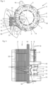
- Fig.1 shows a wound stator 1 in a first phase of an assembly process, with a closed return ring 2, an insulating body 4 with a holding means 7, a winding wire 6, which is wound around the individual radially inward-pointing poles of the stator (not visible here) and is guided between the individual poles in wire guide grooves 8 of the insulating body 4 on the circumference of the stator.
- the winding wire 6 is radially outwardly attached to a stop means 5 of an assembly aid 34 (see Fig. 18 ) is fixed.
- Fig. 2 shows the stator 1 from Fig.1 in a second phase of the assembly process, whereby wire holders 10 (see Fig.5 ) of a connecting means 5 mesh with several wire sections of the winding wire 6 and the connecting means 5 is separated from the insulating body 4.
- the holding means 7 has a guide 12 (see Fig.5 ), into which the connecting means 5 can be pushed with a counter contour 13, wherein the wires are slidably arranged in the wire receptacles along the wire extension direction.
- Fig.3 shows the stator 1 from the Fig. 1 and 2 in a third phase of the assembly process, in which the connecting means 5 is connected to the holding means 7. In this state, there is a positive connection in the axially parallel direction.
- the guide is dimensioned so that there is a frictional connection in the radial direction.
- Fig.4 shows the wound stator 1 in an axial view.
- the stator poles 3 and the routing of the winding wire 6 can be seen.
- This is joined around wire guide means 15, whereby the wire is also partially guided inwards into a winding receiving area of the stator 1 and back in order to lay the wire to the desired position on the connection means 5.
- Deflection means 31 are also provided for this purpose.
- the wire guide means 15, which are used for the arrangement of the winding wires in the connection area, are arranged in a 90° angle sector 30 in which the connection means 5 is completely contained.
- the connection means 5 is mounted on the insulating body 4 and has three insulation displacement contacts 9, which are joined axially (parallel to the motor axis 14) in receiving shafts 11 of the connection means 5.
- the connection means 5 is pushed onto a holding means 7 almost radially.
- the insulation displacement contacts 9 serve as a loss protection in the radial direction until final assembly. In the axial direction there is a positive connection between the connection means
- Fig.5 shows a top view of the wound stator 1, with the return ring 2, the insulating body 4, the connection means 5 and the winding wire 6.
- the magnetically active part of the stator 1 consists of a stack of sheets. Several adjacent sheets of this stack of sheets are radially expanded at three points and form fastening eyes 16 (see also Fig.4 ) for a screw connection with a Housing.
- the insulating body 4 has several wire guide grooves 8 in which the winding wire 6 is laid on the outside circumference of the insulating body 4. Slot linings (not visible here) as part of the insulating body 4 protrude into slots of the stator 1.
- the holding means 7 which is one piece with the insulating body 4 and has the guide 12, onto which the connecting means 5 is pushed in a radially form-fitting manner, with the counter contour 13.
- the holding means also has support means 17 with which the holding means 7 is supported on the return ring 2.
- the connecting means 5 has guide means 18 which serve to guide a connector plug. To facilitate assembly, the guide means 18 are provided with insertion bevels. The guide means 18 project axially much further than the connecting means, which makes assembly of the connector plug easier.
- the connection means 5 has slot-like wire receptacles 10 which are formed into the connection means 5 at different depths so that the wire sections of the winding wire 6 inserted therein are at different levels.
- the different levels are adapted to the axial position of the wire guide grooves 8. This geometric feature serves to lay the winding wire 6 in the most space-saving way possible.
- An insulating end disk 20 is mounted on the opposite side of the stator 1, which has no additional wire guide contours.
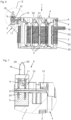
- Fig.6 shows a sectional view of the wound stator 1, with the return 2, the fastening eye 16, the stator poles 3, the insulating body 4, the insulating end plate 20, several stator coils 21, the connection means 5 and the winding wire 6 received in the wire guide grooves 8 and in the wire holder 10 of the connection means 5.
- the insulating body 4 and the insulating end plate 20 have slot linings 23.
- wire passages 22 are formed in the insulating body 4, through which the winding wire 6 is guided from the wire guide grooves 8 to the stator poles 3 and back and from the wire guide means 15 to the stator poles 3 or to the connection means 5.
- the support means 17 can absorb joining force when inserting a connector.
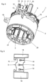
- Fig.8 shows a three-dimensional view of the wound stator 1, with the return ring 2, the insulating end disk 20, the insulating body 4, the stator poles 3, the winding wires 6 and the connection means 5.
- the support means 17 of the holding means 7 and the guide 12 as well as the counter contour 13 of the connection means 5 can be clearly seen. Also shown are the stator coils 21, the fastening eyes 16, the wire holders 10 and the guide means 18.
- Fig.9 shows an individual part of a connection means 5, with the wire holders 10, the counter contours 13, which resemble a slotted guide, and the guide means 18, which are of different widths.
- the wire holders are provided with insertion bevels to make wire assembly easier.
- the slot width of the wire holder 10 is, however, adapted to the wire thickness and is significantly smaller than a winding needle of a needle winding machine with which the winding is produced.
- Fig.10 shows a side view of the connection means 5, with the guide means 18 and a locking means 25, which serves to receive a housing cover section, by means of which the connection means 5 is additionally fixed in a form-fitting manner in the axial direction.
- Fig. 11 represents a plan view of the connection means 5, with the locking means 25, the receiving shafts 11, the wire receptacles 10 and the guide means 18.
- Fig. 12 shows a section BB through the connecting means 5 from Fig. 11 , with the locking means 25, the stop means 24, the wire holder 10 and the receiving shaft 11.
- Fig. 13 shows a section AA through the connection means 5 from Fig. 11 , with a receiving shaft 11 and a rib-like additional guide 26.
- FIG. 14 An enlarged section G from Fig. 13 , shows in Fig. 14 more clearly the details of the connection means 5, with the receiving shaft 11, the wire holder 10, the stop means 24 and the counter contour 13.
- Fig. 15 shows a front view of the insulating body 4 with the holding means 7, which is provided with an additional groove 27 for receiving the additional guide 26 (see Fig. 13 ). Also shown are the wire guide means 15, which are designed as axially projecting pins, and the wire passages 22 between a radially outer and a radially inner stator area. Deflection means 31 radially outside the return ring 2 serve to deflect a winding wire section for the two radially furthest apart wire receptacles 10. No additional deflection means 31 is required for the third wire receptacle 10.
- Fig. 16 shows an enlarged section H from Fig. 15 , with the insulating body 4, the holding means 7, the additional groove 27, the wire guide means 15, the deflection means 31, the wire passages 22 and the groove linings 23, which also insulate the front sides of the stator poles 3.
- bevels 28 are provided on the holding means 7.
- a first depth stop 32 and a second depth stop 33 are provided on the holding means 7 radially outside the return ring 2, which limit the height of the winding wire 6 (in the axial direction). It should be noted that two winding wires 6 are usually placed on top of one another and therefore have different height levels. Crossing points must also be guided with the help of the wire guide means 15 and the further deflection means 31 in such a way that an undesirable increase in height is avoided.
- Fig. 17 shows an exploded view of individual parts of the electric motor, with the insulating body 4, the connecting means 5, with the locking means 25, with insulation displacement contacts 9 and a housing cover 40, on the edge of which a locking tab 39 protrudes parallel to the axis.
- This locking tab 39 is adapted to the locking means 25 and, when installed, forms a positive connection with it. This prevents the connecting means 5 with its counter contour 13 from slipping radially out of the guide 12 of the insulating body 4.
- the housing cover 40 is pot-shaped and has snap means 41 on its pot edge, which can be locked with corresponding snap lugs 42 of the insulating body 4.
- Fig. 18 shows an assembly aid 34 with a stator holder 36 with connection receiving area 37 and with stop points 35, which are designed here as stop pins.
- the assembly aid 34 is also provided with adjustment pins 38, which serve to align the stator in the winding device and in a workpiece carrier.
Landscapes
- Engineering & Computer Science (AREA)
- Power Engineering (AREA)
- Insulation, Fastening Of Motor, Generator Windings (AREA)
- Manufacture Of Motors, Generators (AREA)
- Connections By Means Of Piercing Elements, Nuts, Or Screws (AREA)
Description
- Die Erfindung betrifft ein Verfahren zur Herstellung eines Stators (1) eines elektronisch kommutierten Gleichstrommotors mit einem mehrphasigen Stator (1) und einem Innenrotor, wobei der Stator (1) einen geschlossenen Rückschlussring (2) und eine Vielzahl von mit diesem einstückigen, nach innen gerichteten Statorpolen (3) und einen Isolierstoffkörper (4) mit einem sich radial über den Statoraußendurchmesser erstreckenden Anschlussmittel (5) für einen Wicklungsdraht (6) aufweist, wobei das Anschlussmittel (5) nicht einstückig mit dem Isolierstoffkörper (4) ist, sondern an einem mit dem Isolierstoffkörper (4) einstückigen Haltemittel (7) montiert ist.
- Die Erfindung betrifft zudem einen elektronisch kommutierten Gleichstrommotor mit einem mehrphasigen Stator (1) und einem Innenrotor, wobei der Stator (1) einen geschlossenen Rückschlussring (2) und eine Vielzahl von mit diesem einstückigen, nach innen gerichteten Statorpolen (3) und einen Isolierstoffkörper (4) mit einem sich radial über den Statoraußendurchmesser erstreckenden Anschlussmittel (5) für einen Wicklungsdraht (6) aufweist, wobei das Anschlussmittel (5) nicht einstückig mit dem Isolierstoffkörper (4) ist, sondern an einem mit dem Isolierstoffkörper (4) einstückigen Haltemittel (7) montiert ist, wobei das Anschlussmittel (5) schlitzartige Drahtaufnahmen (10) aufweist, in welchen die darin aufgenommenen Wicklungsdrähte (6) sich nicht verklemmen können, wobei das Anschlussmittel (5) rechtwinklig zu den Drahtaufnahmen (10) ausgerichtete Aufnahmeschächte (11) für Schneid-Klemm-Kontakte (9), Schweiß- oder Lötkontakte aufweist und das Haltemittel (7) eine Führung (12) aufweist, welche mit einer Gegenkontur (13) am Anschlussmittel (5) korrespondiert.
- Elektronisch kommutierte Gleichstrommotoren mit nach innen gerichteten Polen werden je nach Anforderung auf unterschiedliche Weise hergestellt. Sollen kurze Prozesszeiten erreicht werden, eignet sich z. B. ein Einzelpolwickelverfahren, bei dem die Pole auf wirtschaftliche Weise in Gruppen gleichzeitig von außen bewickelt und anschließend zu einem Stator zusammengesetzt und gefügt werden. Jede Grenzfläche zwischen den einzelnen Polen bildet dabei einen magnetischen Widerstand. Die Summe dieser Widerstände verringert den Gesamtwirkungsgrad des Gleichstrommotors. Daher wird dieses Verfahren nicht bei hohen Anforderungen an den Wirkungsgrad verwendet. Hierfür wählt man besser Innenwickelverfahren, wie das Nadelwickeln. Nachteilig beim Nadelwickelverfahren ist jedoch ein relativ großer Bauraumbedarf für die Wickelnadel selbst, die sich einerseits zwischen den Polen bewegen muss und andererseits auch beim Verlegen der Wicklungsdrähte zwischen Drahtführungsmitteln geführt werden muss. Weiter ist es beim Nadelwickeln, insbesondere beim Anschließen der Wicklungsdrähte an Anschlussmitteln je nach Anschlussart erforderlich den Wicklungsdraht achsparallel zu fügen oder zu verlegen, wobei der Draht axial so gesichert sein muss, dass er nicht aus bereits verlegten Abschnitten, z. B. an Umlenkgeometrien herausrutscht. Um dies zu vermeiden sind in der Regel Hinterschnitte an den Umlenkgeometrien vorgesehen. Diese Geometrien erfordern deutlich aufwändigere Spritzgusswerkzeuge mit seitlichen Schiebern. Die Abstände zu den Anschlussstellen müssen auch deshalb relativ groß sein, weil dadurch größere Biegeradien für den Wicklungsdraht möglich sind. Bei zu kleinem Biegeradius lässt sich der Draht häufig nicht über eine Anschlussgeometrie führen ohne bleibende Biegeverformungen zu riskieren. Dies kann zu lockeren oder sich lockernden Drahtabschnitten führen, wonach es zu einer Verkürzung der Lebensdauer kommen kann.
- Aus der
EP 1 722 464 A1 ist ein gattungsgemäßer elektronisch kommutierter Gleichstrommotor bekannt, bei dem die Drähte außen am Isolierstoffkörper verlegt und mit einer radial an dem Isolierstoffkörper anschließenden Kontaktiervorrichtung (Anschlussblock) verbunden werden. Die Wicklung ist dabei so verlegt, dass der Wicklungsdraht vor oder nach der Bewicklung aller einer Phase zugeordneten Statorzähne über ein Kontaktierelement der Kontaktiervorrichtung geführt ist. Der Wicklungsdraht ist jeweils im Bereich des Rückschlusses außen auf dem Isolierstoffkörper verlegt. Da dies auch im Bereich der Kontaktiervorrichtung der Fall ist, erstreckt sich die Kontaktiervorrichtung sehr weit radial nach außen und vergrößert hierdurch den Bauraum erheblich. - Aus der
US 2014/015357 A1 ist eine elektrische Verbinderanordnung zum Bereitstellen einer elektrischen Verbindung mit Magnetdrahtanschlüssen an Elektromotoren mit Kabelbäumen bekannt, umfassend einen Adapter zum Verbinden von Magnetdrähten mit einem Kabelbaum. Ein erstes Gehäuse (10) des Adapters ist an einem Motorgehäuse (30) befestigt und weist erste Anschlüsse auf, die in Anschlussaufnahmekanälen des ersten Gehäuses befestigt sind und isolationsverdrängende Schlitze und passsende Abschnitte aufweisen, wobei die isolationsverdrängenden Schlitzte zum Aufnehmen von Magnetdrähten konfiguriert sind und die zusammenpassenden Abschnitte so konfiguriert sind, dass sie mit den Kontakten eines am Kabelbaum befestigten kuppelbaren Verbinders zusammen passen. Ein zweites Gehäuse des Adapters weist Kontaktaufnahmekanäle mit Aufnahmeabschnitten auf, die so konfiguriert sind, um die Passteile der ersten Anschlüsse und die Aufnahmekanäle des passenden Verbinders aufzunehmen. - Die
US 4 132 460 A offenbart ein elektrisches Anschlussgehäuse, das zur Montage an einem Stator eines Elektromotors vorgesehen ist, umfassend ein Verbindergehäuse mit einem Anschlussgehäuseabschnitt und einer Stabilisierungsrippe, die sich seitlich von einer der Seitenwände des Anschlussgehäuses erstreckt. Das freie Ende der Rippe weist Klemmfinder auf, die so dimensioniert sind, dass sie an Abschnitten der Polelemente des Stators anliegen, wenn sich das Gehäuse an einer Seite des Stators befindet, wobei sich die Rippe nach innen zur Mitte des Stators erstreckt. Die Klemmeinrichtung an dem Ende der Rippe ist derart ausgebildet, dass das Gehäuse sicher an dem Stator montiert werden kann. - Aus der
DE 10 2012 214 088 A1 ist ein elektronisch kommutierter Gleichstrommotor mit einem mehrphasigen Stator und einem Innenrotor bekannt, wobei der Stator einen geschlossenen Rückschlussring und eine Vielzahl von mit diesem einstückigen, nach innen gerichteten Statorpolen und einen Isolierstoffkörper mit einem sich radial über den Statoraußendurchmesser erstreckenden Anschlussmittel für einen Wicklungsdraht aufweist. - Die
EP 1 422 808 A1 offenbart ein Anschlussmittel, welches einen Befestigungspin für einen Wicklungsdraht umfasst, einen mehrteiligen Isolierstoffkörper, bestehend aus den Teilen 41 und 42 sowie dem Steckermodul, wobei das Steckermodul mittels der Zapfen an den Isolierstoffkörper befestigt ist. - Aus der
EP 1 247 322 A1 ist ein Anschlussmittel bekannt, welches nicht mit dem Isolierstoffkörper einstückig ausgeprägt ist, sondern an den, mit dem Isolierstoffkörper einstückig an geformtem Haltemittel montiert ist. - Die
DE 10 2014 113 650 A1 offenbart ein Anschlussmittel, welches von einem Isolierstoffkörper aufgenommen werden kann. - Aus der
US 2005/118886 A1 ist ein Anschlussmittel bekannt, welches nicht einstückig mit dem Isolierstoffkörper ausgeprägt ist, sondern an dem einstückig mit dem Isolierstoffkörper ausgeprägten Haltemittel montiert wird. - Aufgabe der Erfindung ist es bei einem gattungsgemäßen Gleichstrommotor für eine kompakte Bauform mit geringen axialen und radialen Abmessungen, für einen optimalen Wirkungsgrad auch bei Verwendung eines Nadelwickelverfahrens und für eine einfache Herstellbarkeit zu sorgen.
- Diese Aufgabe wird erfindungsgemäß durch die Merkmale des Verfahrensanspruchs 1 und des Vorrichtungsanspruchs 4 gelöst.
- Der besondere Vorteil dieses Verfahrens besteht darin, dass während des Wickelvorgangs zunächst keine Verbindung mit dem später am Haltemittel montierten Anschlussmittel vorgenommen werden muss. Hierdurch entfallen Axialbewegungen im radial äußeren Bereich des Stators, in welchem später das Anschlussmittel festgelegt ist. Nachdem der Stator bewickelt ist und die radial nach außen geführten Drahtabschnitte noch im Montagehilfsmittel festgelegt sind, wird das Anschlussmittel durch eine achsparallele Bewegung auf die Drahtabschnitte radial außerhalb des Haltemittels gefügt und anschließend durch eine Radialbewegung auf das Haltemittel und in dessen Führung geschoben. Die Drahtabschnitte werden durch diese Radialbewegung nicht mitbewegt, sondern sie gleiten in den Drahtaufnahmen ähnlich einer Kämmbewegung. Die Verbindung zwischen dem Anschlussmittel und dem Haltemittel kann durch eine leichte Überpressung kraftschlüssig gestaltet sein. Durch das Fügen der Schneid-Klemm-Kontakte in die Aufnahmeschächte werden die Drähte abisoliert und mit den Schneid-Klemm-Kontakten elektrisch verbunden.
- Ein Verriegelungslappen, der z. B. Teil eines Gehäusedeckels sein kann, verriegelt nach seiner Montage das Anschlussmittel in seiner Lage am Haltemittel.
- Hieraus ergibt sich eine Reihe von Vorteilen. Zunächst besteht für die Wickelnadel mehr Platz um die Drahtenden zu fixieren. Weiter muss die Wickelnadel keine Axialbewegung für eine Fügebewegung mit Anschlussmitteln wie Schneid-Klemm-Kontakten ausführen. Aus diesem Grund sind zum einen keine Rückhaltegeometrien, wie Haken oder Hinterschnitte erforderlich. Dadurch kann das Spritzgusswerkzeug für den Isolierstoffkörper deutlich einfacher und ohne seitliche Schieber ausgeführt sein, wodurch die Herstellung wirtschaftlicher ist. Zum anderen kann der radiale Bauraum verringert werden, da auch für die Axialbewegung Raum zur Verfügung gestellt werden müsste. Das Anschlussmittel weist schlitzartige Drahtaufnahmen auf. Diese sind so dimensioniert, dass der Wicklungsdraht beinahe spielfrei aufgenommen werden kann, aber keine Verklemmung bewirkt. Diese Beweglichkeit ist notwendig, um eine Verschiebung des Anschlussmittels auf das Haltemittel prozesssicher vornehmen zu können.
- Das Anschlussmittel ist weiter mit rechtwinklig zu den Drahtaufnahmen ausgerichteten Aufnahmeschächten für Schneid-Klemm-Kontakte geformt. Die Schneid-Klemm-Kontakte können während der Montage kurzzeitig auch als Halte- oder Verliersicherungsmittel für das Anschlussmittel dienen.
- Der Formschluss wird durch eine Führung im Haltemittel und einer mit dieser korrespondierenden und passenden Gegenkontur am Anschlussmittel erreicht. Diese Verbindung kann kulissenartig ausgeführt sein.
- Weiterbildungen der Erfindung sind in den Unteransprüchen dargestellt. Zweckmäßigerweise ist zwischen dem Anschlussmittel und dem Haltemittel eine formschlüssige Verbindung rechtwinklig zur Fügerichtung vorgesehen. Hierdurch wird eine sichere mechanische Verbindung in achsparalleler Richtung erreicht.
- Eine besonders sichere mechanische Verbindung des Anschlussmittels am Haltemittel und damit am Isolierstoffkörper wird dadurch erreicht, dass die Verbindung des Anschlussmittels an dem Haltemittel durch ein Verriegelungsmittel verriegelt ist. Hierdurch entsteht sowohl in achsparalleler als auch in radialer Richtung ein Formschluss.
- Eine sehr effektive und die Teileanzahl einschränkende Lösung besteht darin, dass das Verriegelungsmittel an einem ohnehin notwendigen Gehäusedeckel vorhanden ist.
- Die Gestaltung des Formwerkzeuges für den Isolierstoffkörper lässt sich wesentlich vereinfachen, indem auf axiale Rückhaltegeometrien an den Drahtführungsmitteln des Isolierstoffkörpers verzichtet wird.
- Nach einer besonders bevorzugten Weiterbildung der Erfindung ist vorgesehen, dass zum Umlenken des Wicklungsdrahtes mehrere Drahtführungsmittel in einem Ringbereich des Isolierstoffkörpers, welcher eine axiale Projektion des Rückschlusringes auf den Isolierstoffkörper darstellt und in einem 90°-Winkelsektor, in welchem das Anschlussmittel vollständig enthalten ist, angeordnet und mit dem Isolierstoffkörper einstückig sind. Diese Drahtführungsmittel dienen insbesondere dazu den Wicklungsdraht so platzsparend wie möglich und so optimal wie möglich in eine parallele Anordnung zu bringen, als Voraussetzung für die Montage des Anschlussmittels.
- Weitere Umlenkmittel, die radial außerhalb dieses Ringbereiches am Haltemittel des Isolierstoffkörpers vorgesehen sind, tragen ebenfalls wesentlich zur optimalen Anordbarkeit der Wicklungsdrähte bei.
- Es hat sich gezeigt, dass eine platzsparende Verlegung des Wicklungsdrahtes insbesondere dadurch erreichbar ist, wenn in dem Winkelsektor der Wicklungsdraht zumindest einmal, bevorzugt zumindest zweimal, nach innen axial vor einen bereits bewickelten Statorpol um ein Drahtführungsmittel geführt ist. Hierdurch wird anderenfalls ungenutzter Bauraum für die optimale Anordnung des Wicklungsdrahtes verwendet.
- Dieser Vorteil wird noch weiter ausgenutzt, indem der Wicklungsdraht Zick-Zack-artig um zumindest zwei Drahtführungsmittel herumgelegt ist.
- Ein Ausführungsbeispiel der Erfindung wird nachfolgend anhand der Zeichnung näher erläutert. Es zeigen:
- Fig. 1
- einen Stator in einer ersten Phase eines Montageprozesses,
- Fig. 2
- den Stator in einer zweiten Phase des Montageprozesses,
- Fig. 3
- den Stator in einer dritten Phase des Montageprozesses,
- Fig. 4
- den bewickelten Stator in einer Axialansicht,
- Fig. 5
- den bewickelten Stator in einer Draufsicht,
- Fig. 6
- eine Schnittansicht des bewickelten Stators,
- Fig. 7
- ein vergrößerter Ausschnitt E aus
Fig. 6 , - Fig. 8
- eine dreidimensionale Ansicht des bewickelten Stators,
- Fig. 9
- eine Einzelteildarstellung eines Anschlussmittels,
- Fig. 10
- eine Seitenansicht des Anschlussmittels,
- Fig. 11
- eine Draufsicht auf das Anschlussmittel,
- Fig. 12
- ein Schnitt B-B durch das Anschlussmittel aus
Fig. 11 , - Fig. 13
- ein Schnitt A-A durch das Anschlussmittel aus
Fig. 11 , - Fig. 14
- ein vergrößerter Ausschnitt G aus
Fig. 13 , - Fig. 15
- eine Stirnansicht auf einen Isolierstoffkörper mit einem Haltemittel,
- Fig. 16
- einen vergrößerten Ausschnitt aus
Fig. 15 , - Fig. 17
- eine Explosionsdarstellung und
- Fig. 18
- ein Montagehilfsmittel.
-
Fig. 1 zeigt einen bewickelten Stator 1 in einer ersten Phase eines Montageprozesses, mit einem geschlossenen Rückschlussring 2, einem Isolierstoffkörper 4 mit einem Haltemittel 7, einen Wicklungsdraht 6, welcher um die einzelnen radial nach innen weisenden Pole des Stators gewickelt (hier nicht erkennbar) und zwischen den einzelnen Polen in Drahtführungsrillen 8 des Isolierstoffkörpers 4 am Umfang des Stators geführt sind. Der Wicklungsdraht 6 ist radial nach außen an einem Anschlagmittel 5 eines Montagehilfsmittels 34 (sieheFig. 18 ) fixiert. -
Fig. 2 zeigt den Stator 1 ausFig. 1 in einer zweiten Phase des Montageprozesses, wobei Drahtaufnahmen 10 (sieheFig. 5 ) eines Anschlussmittels 5 mit mehreren Drahtabschnitten des Wicklungsdrahtes 6 kämmen und das Anschlussmittel 5 vom Isolierstoffkörper 4 getrennt ist. Das Haltemittel 7 weist eine Führung 12 (sieheFig. 5 ) auf, in welche das Anschlussmittel 5 mit einer Gegenkontur 13 aufschiebbar ist, wobei die Drähte in den Drahtaufnahmen entlang der Drahterstreckungsrichtung gleitbar angeordnet sind. -
Fig. 3 zeigt den Stator 1 aus denFig. 1 und 2 in einer dritten Phase des Montageprozesses, in welchem das Anschlussmittel 5 mit dem Haltemittel 7 verbunden ist. In diesem Zustand besteht eine formschlüssige Verbindung in achsparalleler Richtung. Die Führung ist so dimensioniert, dass eine reibschlüssige Verbindung in radialer Richtung besteht. -
Fig. 4 zeigt den bewickelten Stator 1 in einer Axialansicht. Hier sind die Statorpole 3 und die Verlegung des Wicklungsdrahtes 6 zu erkennen. Dieser ist um Drahtführungsmittel 15 gefügt, wobei der Draht teilweise auch nach innen in einen Wicklungsaufnahmebereich des Stators 1 und zurück geführt wird, um den Draht an die gewünschte Position am Anschlussmittel 5 zu verlegen. Hierzu sind zusätzlich auch Umlenkmittel 31 vorgesehen. Die Drahtführungsmittel 15, welche für die Anordnung der Wicklungsdrähte im Anschlussbereich dienen, sind in einem 90°-Winkelsektor 30 angeordnet, in welchem das Anschlussmittel 5 vollständig enthalten ist. Das Anschlussmittel 5 ist am Isolierstoffkörper 4 montiert und weist drei Schneid-Klemm-Kontakte 9 auf, die in Aufnahmeschächten 11 des Anschlussmittels 5 axial (parallel zur Motorachse 14) gefügt sind. Das Anschlussmittel 5 ist an einem Haltemittel 7 annähernd radial aufgeschoben. Die Schneid-Klemm-Kontakte 9 dienen bis zur Endmontage als Verliersicherung in radialer Richtung. In Axialrichtung besteht ein Formschluss zwischen Anschlussmittel 5 und Haltemittel 7. -
Fig. 5 zeigt eine Draufsicht auf den bewickelten Stator 1, mit dem Rückschlussring 2, dem Isolierstoffkörper 4, dem Anschlussmittel 5 und dem Wicklungsdraht 6. Der magnetisch aktive Teil des Stators 1 besteht aus einem Blechstapel. Mehrere benachbarte Bleche dieses Blechstapels sind radial an drei Stellen erweitert und bilden Befestigungsaugen 16 (siehe auchFig. 4 ) für eine Verschraubung mit einem Gehäuse. Der Isolierstoffkörper 4 weist mehrere Drahtführungsrillen 8 auf, in welchen der Wicklungsdraht 6 außen am Umfang des Isolierstoffkörpers 4 verlegt ist. Nutauskleidungen (hier nicht erkennbar) als Teil des Isolierstoffkörpers 4 ragen in Nuten des Stators 1 ein. Weiter zu erkennen ist das mit dem Isolierstoffkörper 4 einstückige Haltemittel 7 mit der Führung 12, an welchem radial formschlüssig das Anschlussmittel 5 aufgeschoben ist, mit der Gegenkontur 13. Das Haltemittel weist weiter Abstützmittel 17 auf, mit welchen sich das Haltemittel 7 am Rückschlussring 2 abstützt. Das Anschlussmittel 5 weist Führungsmittel 18 auf, welche zur Führung eines Anschlusssteckers dienen. Zur leichteren Montage sind die Führungsmittel 18 mit Einführschrägen versehen. Die Führungsmittel 18 springen axial deutlich weiter vor als das Anschlussmittel, weshalb die Montage des Anschlusssteckers erleichtert ist. Das Anschlussmittel 5 weist schlitzartige Drahtaufnahmen 10 auf, welche unterschiedlich tief in das Anschlussmittel 5 eingeformt sind, so dass die darin eingelegten Drahtabschnitte des Wicklungsdrahts 6 auf unterschiedlichen Niveaus liegen. Wie gestrichelte Linien 19 verdeutlichen, sind die unterschiedlichen Niveaus an die axiale Lage der Drahtführungsrillen 8 angepasst. Diese geometrische Besonderheit dient dazu den Wicklungsdraht 6 möglichst platzsparend zu verlegen. Auf der gegenüberliegenden Seite des Stators 1 ist eine Isolierendscheibe 20 montiert, welche keine zusätzlichen Drahtführungskonturen aufweist. -
Fig. 6 zeigt eine Schnittansicht des bewickelten Stators 1, mit dem Rückschluss 2, dem Befestigungsauge 16, den Statorpolen 3, dem Isolierstoffkörper 4, der Isolierendscheibe 20, mehreren Statorspulen 21, dem Anschlussmittel 5 und dem in den Drahtführungsrillen 8 und in der Drahtaufnahme 10 des Anschlussmittels 5 aufgenommenen Wicklungsdraht 6. Der Isolierstoffkörper 4 und die Isolierendscheibe 20 weisen Nutauskleidungen 23 auf. Weiter sind im Isolierstoffkörper 4 Drahtdurchgänge 22 eingeformt, durch welche der Wicklungsdraht 6 von den Drahtführungsrillen 8 zu den Statorpolen 3 und zurück und von den Drahtführungsmitteln 15 zu den Statorpolen 3 oder zum Anschlussmittel 5 geführt sind. Durch die Abstützmittel 17 kann Fügekraft beim Einstecken eines Anschlusssteckers aufgenommen werden. - Die weiteren Einzelheiten zeigt deutlicher die vergrößerte Einzelheit E (
Fig. 7 ), mit dem Isolierstoffkörper 4, dem Rückschlussring 2, dem Haltemittel 7, dem Anschlussmittel 5, dem Drahtführungsmittel 15 und dem Wicklungsdraht 6. Wie deutlich zu erkennen, sind zwei Drähte 6 in der schlitzartigen Drahtaufnahme 10 aufgenommen. Dabei handelt es sich um einen von dem Anschlussmittel 5 wegverlegten Draht und einen zum Anschlussmittel zurückverlegten Draht. Im Aufnahmeschacht 11 ist rechtwinklig zur Drahterstreckungsrichtung der Schneid-Klemm-Kontakt 9 gefügt, der zur Aufnahme einer Kontaktzunge eines Anschlusssteckers dient und entsprechend geformt ist. Wie nicht zu erkennen ist verkrallen sich Widerhaken des Schneid-Klemm-Kontakts 9 in den Begrenzungsflächen des Aufnahmeschachts 11. Ein Anschlagmittel 24 ist innerhalb der Drahtaufnahme 10 mitgeformt und dient zur Festlegung des Niveaus, auf welchem die Wicklungsdrähte 6 die Drahtaufnahme 10 queren. Schließlich ist das Führungsmittel 18 erkennbar, das für die einfachere Montage des Anschlusssteckers mit Schrägen 29 versehen ist. -
Fig. 8 zeigt eine dreidimensionale Ansicht des bewickelten Stators 1, mit dem Rückschlussring 2, der Isolierendscheibe 20, dem Isolierstoffkörper 4, den Statorpolen 3, den Wicklungsdrähten 6 und dem Anschlussmittel 5. Deutlich sind die Abstützmittel 17 des Haltemittels 7 und die Führung 12, sowie die Gegenkontur 13 des Anschlussmittels 5 zu erkennen. Weiter sind gezeigt die Statorspulen 21, die Befestigungsaugen 16, die Drahtaufnahmen 10 und die Führungsmittel 18. -
Fig. 9 zeigt eine Einzelteildarstellung eines Anschlussmittels 5, mit den Drahtaufnahmen 10, den Gegenkonturen 13, welche einer Kulissenführung ähneln und die Führungsmittel 18, welche unterschiedlich breit ausgeführt sind. Die Drahtaufnahmen sind mit Einführschrägen zur leichteren Drahtmontage versehen. Die Schlitzbreite der Drahtaufnahme 10 ist jedoch an die Drahtstärke angepasst und ist deutlich geringer als eine Wickelnadel einer Nadelwickelmaschine, mit welcher die Wicklung gefertigt ist. -
Fig. 10 zeigt eine Seitenansicht des Anschlussmittels 5, mit dem Führungsmittel 18 und einem Verriegelungsmittel 25, welches zur Aufnahme eines Gehäusedeckelabschnitts dient, durch welchen das Anschlussmittel 5 in Axialrichtung zusätzlich formschlüssig fixiert ist. -
Fig. 11 stellt eine Draufsicht auf das Anschlussmittel 5 dar, mit dem Verriegelungsmittel 25, den Aufnahmeschächten 11, den Drahtaufnahmen 10 und den Führungsmitteln 18. -
Fig. 12 zeigt einen Schnitt B-B durch das Anschlussmittel 5 ausFig. 11 , mit dem Verriegelungsmittel 25, dem Anschlagmittel 24, der Drahtaufnahme 10 und dem Aufnahmeschacht 11. -
Fig. 13 zeigt einen Schnitt A-A durch das Anschlussmittel 5 ausFig. 11 , mit einem Aufnahmeschacht 11 und einer rippenartigen Zusatzführung 26. - Ein vergrößerter Ausschnitt G aus
Fig. 13 , zeigt inFig. 14 deutlicher die Einzelheiten des Anschlussmittels 5, mit dem Aufnahmeschacht 11, der Drahtaufnahme 10, dem Anschlagmittel 24 und der Gegenkontur 13. -
Fig. 15 zeigt eine Stirnansicht auf den Isolierstoffkörper 4 mit dem Haltemittel 7, welches mit einer Zusatznut 27 zur Aufnahme der Zusatzführung 26 (sieheFig. 13 ) versehen ist. Weiter sind die Drahtführungsmittel 15 gezeigt, die als axial vorspringende Zapfen ausgebildet sind, sowie die Drahtdurchgänge 22 zwischen einem radial äußeren und einem radial inneren Statorbereich. Umlenkmittel 31 radial außerhalb des Rückschlussrings 2 dienen zur Umlenkung eines Wicklungsdrahtabschnitts für die beiden radial am weitesten entfernten Drahtaufnahmen 10. Bei der dritten Drahtaufnahme 10 ist kein zusätzliches Umlenkmittel 31 erforderlich. -
Fig. 16 zeigt einen vergrößerten Ausschnitt H ausFig. 15 , mit dem Isolierstoffkörper 4, dem Haltemittel 7, der Zusatznut 27, den Drahtführungsmitteln 15, dem Umlenkmittel 31, den Drahtdurchgängen 22 und den Nutauskleidungen 23, welche auch Stirnseiten der Statorpole 3 isolieren. Zur leichteren Montage des Anschlussmittels 5 sind am Haltemittel 7 Fasen 28 vorgesehen. Am Haltemittel 7 radial außerhalb des Rückschlussrings 2 sind ein erster Tiefenanschlag 32 und ein zweiter Tiefenanschlag 33 vorgesehen, welche die Höhenlage des Wicklungsdrahts 6 (in Axialrichtung) begrenzen. Hierbei ist zu beachten, dass in der Regel zwei Wicklungsdrähte 6 übereinander gelegt sind und daher unterschiedliche Höhenniveaus einnehmen. Auch Kreuzungspunkte müssen mit Hilfe der Drahtführungsmittel 15 und den weiteren Umlenkmitteln 31 so geführt sein, dass ein unerwünschter Höhenaufbau vermieden wird. -
Fig. 17 zeigt eine Explosionsdarstellung von einzelnen Teilen des Elektromotors, mit dem Isolierstoffkörper 4, dem Anschlussmittel 5, mit dem Verriegelungsmittel 25, mit Schneid-Klemm-Kontakten 9 und einem Gehäusedeckel 40, an dessen Rand ein Verriegelungslappen 39 achsparallel vorspringt. Dieser Verriegelungslappen 39 ist an das Verriegelungsmittel 25 angepasst und geht im montierten Zustand mit diesem einen Formschluss ein. Dadurch wird verhindert, dass das Anschlussmittel 5 mit seiner Gegenkontur 13 radial aus der Führung 12 des Isolierstoffkörpers 4 rutschen kann. Der Gehäusedeckel 40 ist topfförmig ausgebildet und weist an seinem Topfrand Schnappmittel 41 auf, welche mit korrespondierenden Schnappnasen 42 des Isolierstoffkörpers 4 verrastbar sind. -
Fig. 18 zeigt ein Montagehilfsmittel 34, mit einer Statoraufnahme 36 mit Anschlussaufnahmebereich 37 und mit Anschlagstellen 35, die hier als Anschlagstifte ausgeführt sind. Das Montagehilfsmittel 34 ist weiter mit Justierstiften 38 versehen, welche zur Ausrichtung des Stators in der Wickelvorrichtung und in einem Werkstückträger dienen. -
1 Stator 33 Zweiter Tiefenanschlag 2 Rückschlussring 34 Montagehilfsmittel 3 Statorpol 35 Anschlagstelle 4 Isolierstoffkörper 36 Statoraufnahme 5 Anschlussmittel 37 Anschlussaufnahmebereich 6 Wicklungsdraht 38 Justierstift 7 Haltemittel 39 Verriegelungslappen 8 Drahtführungsrille 40 Gehäusedeckel 9 Schneid-Klemm-Kontakt 41 Schnappmittel 10 Drahtaufnahmen 42 Schnappnase 11 Aufnahmeschacht 12 Führung 13 Gegenkontur 14 Motorachse 15 Drahtführungsmittel 16 Befestigungsauge 17 Abstützmittel 18 Führungsmittel 19 Gestrichelte Linie 20 Isolierendscheibe 21 Statorspule 22 Drahtdurchgang 23 Nutauskleidung 24 Anschlagmittel 25 Verriegelungsmittel 26 Zusatzführung 27 Zusatznut 28 Fase 29 Schräge 30 Winkelsektor 31 Umlenkmittel 32 erster Tiefenanschlag
Claims (12)
- Verfahren zur Herstellung eines Stators (1) eines elektronisch kommutierten Gleichstrommotors mit einem Motorachse (14), einem mehrphasigen Stator (1) und einem Innenrotor, wobei der Stator (1) einen geschlossenen Rückschlussring (2) und eine Vielzahl von mit diesem einstückigen, nach innen gerichteten Statorpolen (3) und einen Isolierstoffkörper (4) mit einem sich radial über den Statoraußendurchmesser erstreckenden Anschlussmittel (5) für einen Wicklungsdraht (6) aufweist, dadurch gekennzeichnet, in dass das Anschlussmittel (5) nicht einstückig mit dem Isolierstoffkörper (4) ist, sondern an einem mit dem Isolierstoffkörper (4) einstückigen Haltemittel (7) montiert ist, und dadurch gekennzeichnet durch folgende Verfahrensschritte- Bereitstellen eines Montagehilfsmittels (34) zum Anschlagen der Wicklungsdrähte (6),- Bereitstellen eines isolierten Stators (1),- Einlegen des isolierten Stators (1) in das Montagehilfsmittel (34),- Einlegen dieser Anordnung in eine Wickelvorrichtung,- Anschlagen eines Wicklungsdrahtes (6) an einer radial außerhalb des Stators (1) angeordneten Anschlagstelle (35) des Montagehilfsmittels (34),- Fügen des Drahtes einer ersten Phase um nacheinander einen ersten bis zu einem n-ten Pol des Stators (1),- Führen des Drahtes zu einer zweiten Anschlagstelle des Montagehilfsmittels (34) und Anschlagen des Drahtes an diese zweite Anschlagstelle,- unterbrechungsloses Fügen desselben Drahtes als zweite Phase um nacheinander einen ersten bis zu einem n-ten weiteren Pol des Stators (1),- Führen des Drahtes zu einer dritten Anschlagstelle des Montagehilfsmittels (34) und Anschlagen des Drahtes an diese dritte Anschlagstelle,- unterbrechungsloses Fügen desselben Drahtes als dritte Phase um nacheinander einen ersten bis zu einem n-ten weiteren Pol des Stators (1),- Führen des Drahtes zu der ersten Anschlagstelle und Anschlagen an diese,- Fügen in achsparalleler Richtung von schlitzartigen Drahtaufnahmen (10) des Anschlussmittels (5) in parallel angeordneten Wicklungsdrahtabschnitte zwischen Isolierstoffkörper (4) und den Anschlagstellen (35) des Montagehilfsmittels (34) rechtwinklig zur Drahterstreckung,- Aufschieben einer Gegenkontur (13) des Anschlussmittels (5) durch eine Radialbewegung auf das Haltemittel (7) in eine Führung (12) des Haltemittels (7) sodass die Verbindung des Anschlussmittels (5) an dem Haltemittel (7) in achsparalleler Richtung formschlüssig ist,- Fügen der Schneid-Klemm-Kontakte (9), Schweiß- oder Lötkontakte in achsparalleler Richtung in Aufnahmeschächte (11) des Anschlussmittels (5),- Abtrennen der Drahtabschnitte radial außerhalb des Anschlussmittels (5), z. B. durch eine Klinge.
- Verfahren zur Herstellung eines Stators (1) nach Anspruch 1, gekennzeichnet durch den Verfahrensschritt: Montage eines Verriegelungslappens (39) an den Stator (1) und Verriegeln des Anschlussmittels (5) durch Formschluss.
- Verfahren zur Herstellung eines Stators (1) nach Anspruch 1, gekennzeichnet durch den Verfahrensschritt: Montage eines Gehäusedeckels (40) mit einem damit einstückigen Verriegelungslappens (39) an den Stator (1) und Verriegeln des Anschlussmittels (5) durch Formschluss.
- Elektronisch kommutierter Gleichstrommotor mit einem Motorachse (14), einem mehrphasigen Stator (1) und einem Innenrotor, wobei der Stator (1) einen geschlossenen Rückschlussring (2) und eine Vielzahl von mit diesem einstückigen, nach innen gerichteten Statorpolen (3) und einen Isolierstoffkörper (4) mit einem sich radial über den Statoraußendurchmesser erstreckenden Anschlussmittel (5) für einen Wicklungsdraht (6) aufweist, dadurch gekennzeichnet, dass das Anschlussmittel (5) nicht einstückig mit dem Isolierstoffkörper (4) ist, sondern an einem mit dem Isolierstoffkörper (4) einstückigen Haltemittel (7) montiert ist, wobei das Anschlussmittel (5) schlitzartige Drahtaufnahmen (10) aufweist, in welchen die darin aufgenommenen radial nach außen geführten Wicklungsdrahtabschnitte sich nicht verklemmen können, wobei das Anschlussmittel (5) rechtwinklig zu den Drahtaufnahmen (10) ausgerichtete Aufnahmeschächte (11) für Schneid-Klemm-Kontakte (9), Schweiß- oder Lötkontakte aufweist und das Haltemittel (7) eine Führung (12) aufweist, in welche das Anschlussmittel (5) mit einer Gegenkontur (13) durch eine Radialbewegung auf das Haltemittel (7) aufschiebbar ist, sodass die Verbindung des Anschlussmittels (5) an dem Haltemittel (7) in achsparalleler Richtung formschlüssig ist.
- Elektronisch kommutierter Gleichstrommotor nach Anspruch 4, dadurch gekennzeichnet, dass die Verbindung des Anschlussmittels (5) an dem Haltemittel (7) durch einen Verriegelungslappen (39) verriegelt ist.
- Elektronisch kommutierter Gleichstrommotor nach Anspruch 5, dadurch gekennzeichnet, dass der Verriegelungslappen (39) mit einem Gehäuseteil, z. B. einem Gehäusedeckel (40) des Gleichstrommotors einstückig ist.
- Elektronisch kommutierter Gleichstrommotor einem der Ansprüche 4 bis 6, dadurch gekennzeichnet, dass zum Umlenken des Wicklungsdrahtes (6) mehrere Drahtführungsmittel (15) in einem Ringbereich des Isolierstoffkörpers (4), welcher eine axiale Projektion des Rückschlussringes (2) auf den Isolierstoffkörper (4) darstellt und in einem 90°-Winkelsektor (30), in welchem das Anschlussmittel (5) vollständig enthalten ist, angeordnet und mit dem Isolierstoffkörper (4) einstückig sind.
- Elektronisch kommutierter Gleichstrommotor nach Anspruch 7, dadurch gekennzeichnet, dass weitere Umlenkmittel (31) radial außerhalb dieses Ringbereiches am Haltemittel (7) des Isolierstoffkörpers (4) vorgesehen sind.
- Elektronisch kommutierter Gleichstrommotor nach Anspruch 8, dadurch gekennzeichnet, dass in dem Winkelsektor (30) der Wicklungsdraht (6) zumindest einmal nach innen axial vor einen bereits bewickelten Statorpol (3) um ein Drahtführungsmittel (15) geführt ist.
- Elektronisch kommutierter Gleichstrommotor nach Anspruch 8, dadurch gekennzeichnet, dass in dem Winkelsektor (30) der Wicklungsdraht (6) zumindest zweimal nach innen axial vor einen bereits bewickelten Statorpol (3) um ein jeweils unterschiedliches Drahtführungsmittel (15) geführt ist.
- Elektronisch kommutierter Gleichstrommotor nach Anspruch 8, dadurch gekennzeichnet, dass der Wicklungsdraht (6) Zick-Zack-artig um zumindest zwei Drahtführungsmittel (15) herumgelegt ist.
- Elektronisch kommutierter Gleichstrommotor nach Anspruch 4, dadurch gekennzeichnet, dass kein Drahtführungsmittel (15) vorhanden ist, welches in achsparalleler Richtung wirkende Rückhaltegeometrien aufweist.
Applications Claiming Priority (2)
| Application Number | Priority Date | Filing Date | Title |
|---|---|---|---|
| DE102015208209.1A DE102015208209B4 (de) | 2015-05-04 | 2015-05-04 | Verfahren zur Herstellung eines Stators eines elektronisch kommutierten Gleichstrommotors |
| PCT/DE2016/200129 WO2016177365A1 (de) | 2015-05-04 | 2016-03-10 | Elektronisch kommutierter gleichstrommotor |
Publications (2)
| Publication Number | Publication Date |
|---|---|
| EP3292590A1 EP3292590A1 (de) | 2018-03-14 |
| EP3292590B1 true EP3292590B1 (de) | 2024-08-07 |
Family
ID=55701649
Family Applications (1)
| Application Number | Title | Priority Date | Filing Date |
|---|---|---|---|
| EP16715442.6A Active EP3292590B1 (de) | 2015-05-04 | 2016-03-10 | Verfahren zur herstellung eines stators und elektronisch kommutierter gleichstrommotor |
Country Status (6)
| Country | Link |
|---|---|
| EP (1) | EP3292590B1 (de) |
| JP (1) | JP6518006B2 (de) |
| KR (1) | KR101958890B1 (de) |
| CN (1) | CN107534348B (de) |
| DE (1) | DE102015208209B4 (de) |
| WO (1) | WO2016177365A1 (de) |
Families Citing this family (7)
| Publication number | Priority date | Publication date | Assignee | Title |
|---|---|---|---|---|
| JP6591574B2 (ja) * | 2018-01-15 | 2019-10-16 | 本田技研工業株式会社 | 波巻コイルの保持装置、保持方法及び挿入方法 |
| DE102018102976A1 (de) * | 2018-02-09 | 2019-08-14 | Nidec Corp. | Drahthalter |
| DE102018221040A1 (de) * | 2018-12-05 | 2020-06-10 | Robert Bosch Gmbh | Stator für eine elektrische Maschine, eine elektrische Maschine und Verfahren zum Herstellen eines solchen Stators |
| DE102019205256A1 (de) | 2019-04-11 | 2020-10-15 | Brose Fahrzeugteile SE & Co. Kommanditgesellschaft, Würzburg | Antriebsvorrichtung mit einem bürstenlosen Elektromotor |
| DE102019206641A1 (de) * | 2019-05-08 | 2020-11-12 | Brose Fahrzeugteile SE & Co. Kommanditgesellschaft, Würzburg | Stator eines Elektromotors |
| DE102020132455A1 (de) | 2020-12-07 | 2022-06-09 | Schaeffler Technologies AG & Co. KG | Stator |
| DE102023201624A1 (de) * | 2023-02-22 | 2024-08-22 | Brose Fahrzeugteile SE & Co. Kommanditgesellschaft, Würzburg | Elektromotor, insbesondere Kühlerlüftermotor |
Citations (5)
| Publication number | Priority date | Publication date | Assignee | Title |
|---|---|---|---|---|
| EP1247322A1 (de) * | 2000-01-12 | 2002-10-09 | Toshiba Carrier Corporation | Anordnung der stator-wicklungsanschlüsse bei einem elektromotor |
| EP1422808A1 (de) * | 2002-11-20 | 2004-05-26 | Minebea Co., Ltd. | Statorstruktur eines Resolvers |
| US20050118886A1 (en) * | 2003-11-28 | 2005-06-02 | Samsung Gwang Ju Electronics Co., Ltd. | Motor |
| DE102012214088A1 (de) * | 2011-08-09 | 2013-02-14 | Nidec Corp. | Motor |
| DE102014113650A1 (de) * | 2013-09-26 | 2015-03-26 | Fanuc Corporation | Stator mit Abstützbock, Elektromotor mit einem Stator, und Verfahren zur Herstellung eines Elektromotors |
Family Cites Families (11)
| Publication number | Priority date | Publication date | Assignee | Title |
|---|---|---|---|---|
| US4132460A (en) * | 1977-11-07 | 1979-01-02 | Amp Incorporated | Electrical connections to coil windings |
| JPH0644290Y2 (ja) * | 1988-09-02 | 1994-11-14 | 三菱電機株式会社 | 電気機器の口出線固定装置 |
| JPH04185253A (ja) * | 1990-11-20 | 1992-07-02 | Matsushita Seiko Co Ltd | 樹脂モールドモータの固定子 |
| JPH1014154A (ja) * | 1996-06-26 | 1998-01-16 | Matsushita Electric Ind Co Ltd | 電気機器のリード線の支持装置 |
| DE10045471A1 (de) * | 2000-09-14 | 2002-04-04 | Miele & Cie | Stator für Elektromotoren, insbesondere für Asynchronmotoren |
| JP2002325385A (ja) * | 2001-02-22 | 2002-11-08 | Moric Co Ltd | 回転界磁型電気機器のステータ構造 |
| KR100438626B1 (ko) * | 2002-10-16 | 2004-07-02 | 엘지전자 주식회사 | 단자대를 구비한 아웃터 로터 타입 단상 유도 전동기 |
| JP2004173393A (ja) * | 2002-11-19 | 2004-06-17 | Fujitsu General Ltd | 電動機 |
| EP1722464B1 (de) * | 2005-05-11 | 2019-05-08 | Brose Fahrzeugteile GmbH & Co. KG, Würzburg | Verfahren zum Bewickeln des Stators eines Elektromotors und Stator für einen Elektromotor |
| US8753141B2 (en) * | 2012-07-10 | 2014-06-17 | Tyco Electronics Corporation | Adapter for connecting a harness to magnet wires |
| JP6139203B2 (ja) * | 2013-03-25 | 2017-05-31 | ミネベアミツミ株式会社 | ステッピングモータ |
-
2015
- 2015-05-04 DE DE102015208209.1A patent/DE102015208209B4/de active Active
-
2016
- 2016-03-10 CN CN201680025641.XA patent/CN107534348B/zh active Active
- 2016-03-10 WO PCT/DE2016/200129 patent/WO2016177365A1/de not_active Ceased
- 2016-03-10 KR KR1020177034955A patent/KR101958890B1/ko active Active
- 2016-03-10 EP EP16715442.6A patent/EP3292590B1/de active Active
- 2016-03-10 JP JP2018509970A patent/JP6518006B2/ja active Active
Patent Citations (5)
| Publication number | Priority date | Publication date | Assignee | Title |
|---|---|---|---|---|
| EP1247322A1 (de) * | 2000-01-12 | 2002-10-09 | Toshiba Carrier Corporation | Anordnung der stator-wicklungsanschlüsse bei einem elektromotor |
| EP1422808A1 (de) * | 2002-11-20 | 2004-05-26 | Minebea Co., Ltd. | Statorstruktur eines Resolvers |
| US20050118886A1 (en) * | 2003-11-28 | 2005-06-02 | Samsung Gwang Ju Electronics Co., Ltd. | Motor |
| DE102012214088A1 (de) * | 2011-08-09 | 2013-02-14 | Nidec Corp. | Motor |
| DE102014113650A1 (de) * | 2013-09-26 | 2015-03-26 | Fanuc Corporation | Stator mit Abstützbock, Elektromotor mit einem Stator, und Verfahren zur Herstellung eines Elektromotors |
Also Published As
| Publication number | Publication date |
|---|---|
| EP3292590A1 (de) | 2018-03-14 |
| DE102015208209B4 (de) | 2025-08-21 |
| KR101958890B1 (ko) | 2019-03-18 |
| JP6518006B2 (ja) | 2019-05-22 |
| JP2018523463A (ja) | 2018-08-16 |
| WO2016177365A1 (de) | 2016-11-10 |
| KR20180003591A (ko) | 2018-01-09 |
| CN107534348A (zh) | 2018-01-02 |
| DE102015208209A1 (de) | 2016-11-10 |
| CN107534348B (zh) | 2020-02-14 |
Similar Documents
| Publication | Publication Date | Title |
|---|---|---|
| DE102015208209B4 (de) | Verfahren zur Herstellung eines Stators eines elektronisch kommutierten Gleichstrommotors | |
| DE102015200089B4 (de) | Stator für eine elektrische Maschine und Verfahren zum Herstellen eines solchen | |
| EP3682528B1 (de) | Stator für eine elektrische maschine, eine elektrische maschine und verfahren zum herstellen eines solchen stators | |
| EP3641105B1 (de) | Gleichstrommotor und verfahren zu seiner herstellung | |
| DE102015200095A1 (de) | Stator für eine elektrische Maschine und Verfahren zum Herstellen eines solchen | |
| DE102015208210B4 (de) | Elektronisch kommutierter Gleichstrommotor | |
| DE102009016990A1 (de) | Stator, Motor und Verfahren zur Herstellung eines Stators | |
| DE102012024534A1 (de) | Verfahren zur Herstellung eines Stators, Vorrichtung zur Herstellung eines Stators, und Stator | |
| DE102005001705A1 (de) | Verfahren zur Herstellung von Ankern, Verfahren zur Herstellung von Elektromotoren sowie Anker | |
| DE102018214111A1 (de) | Stator für eine elektrische Maschine, eine elektrische Maschine und Verfahren zum Herstellen einer solchen elektrischen Maschine | |
| DE102017206187A1 (de) | Motor mit Verdrahtungsplatte, die durch Verbinden einer Wicklung durch Crimpen ausgebildet wird | |
| DE112012006066T5 (de) | Anker für eine rotierende elektrische Maschine | |
| EP3644460B1 (de) | Stromschienensystem | |
| DE1222566B (de) | Elektrischer Umschalter mit wenigstens einer beweglichen, mit Kontaktteilen versehenen Lamelle | |
| DE112004001898T5 (de) | Kurzschlußteil, Kommutator und Verfahren zur Herstellung eines Kurzschlußteils | |
| DE202010008762U1 (de) | Elektrische Anschlussvorrichtung | |
| DE102015211836A1 (de) | Verfahren zum Bewickeln eines Stators, sowie ein Stator und eine elektrische Maschine beinhaltend einen solchen Stator | |
| EP3560077B1 (de) | Verfahren zum bewickeln und kontaktieren eines stators sowie stator für einen elektromotor | |
| DE10233251A1 (de) | Joch für eine elektromagnetische Kupplung | |
| DE102011078025A1 (de) | Wickelkopfträger für einen Stator einer elektrischen Maschine | |
| DE102018206003A1 (de) | Vorrichtung und Verfahren zur Ausrichtung einer Hairpinwicklung | |
| EP2600470A1 (de) | Anschlussvorrichtung für ein Flachbandkabel und elektrisches Gerät mit angeschlossenem Flachbandkabel | |
| EP3641104B1 (de) | Gleichstrommotor und verfahren zur herstellung eines gleichstrommotors | |
| DE102012211468A1 (de) | Spulenträger mit integrierten Haltern für das Phasenisolationspapier | |
| WO2014206825A2 (de) | Vorrichtung und spulenträger für elektrische maschine und verfahren zum anordnen einer derartigen vorrichtung an einem derartigen spulenträger |
Legal Events
| Date | Code | Title | Description |
|---|---|---|---|
| STAA | Information on the status of an ep patent application or granted ep patent |
Free format text: STATUS: THE INTERNATIONAL PUBLICATION HAS BEEN MADE |
|
| PUAI | Public reference made under article 153(3) epc to a published international application that has entered the european phase |
Free format text: ORIGINAL CODE: 0009012 |
|
| STAA | Information on the status of an ep patent application or granted ep patent |
Free format text: STATUS: REQUEST FOR EXAMINATION WAS MADE |
|
| 17P | Request for examination filed |
Effective date: 20171009 |
|
| AK | Designated contracting states |
Kind code of ref document: A1 Designated state(s): AL AT BE BG CH CY CZ DE DK EE ES FI FR GB GR HR HU IE IS IT LI LT LU LV MC MK MT NL NO PL PT RO RS SE SI SK SM TR |
|
| AX | Request for extension of the european patent |
Extension state: BA ME |
|
| DAV | Request for validation of the european patent (deleted) | ||
| DAX | Request for extension of the european patent (deleted) | ||
| STAA | Information on the status of an ep patent application or granted ep patent |
Free format text: STATUS: EXAMINATION IS IN PROGRESS |
|
| 17Q | First examination report despatched |
Effective date: 20210317 |
|
| GRAP | Despatch of communication of intention to grant a patent |
Free format text: ORIGINAL CODE: EPIDOSNIGR1 |
|
| STAA | Information on the status of an ep patent application or granted ep patent |
Free format text: STATUS: GRANT OF PATENT IS INTENDED |
|
| INTG | Intention to grant announced |
Effective date: 20240301 |
|
| GRAS | Grant fee paid |
Free format text: ORIGINAL CODE: EPIDOSNIGR3 |
|
| GRAA | (expected) grant |
Free format text: ORIGINAL CODE: 0009210 |
|
| STAA | Information on the status of an ep patent application or granted ep patent |
Free format text: STATUS: THE PATENT HAS BEEN GRANTED |
|
| AK | Designated contracting states |
Kind code of ref document: B1 Designated state(s): AL AT BE BG CH CY CZ DE DK EE ES FI FR GB GR HR HU IE IS IT LI LT LU LV MC MK MT NL NO PL PT RO RS SE SI SK SM TR |
|
| REG | Reference to a national code |
Ref country code: GB Ref legal event code: FG4D Free format text: NOT ENGLISH |
|
| REG | Reference to a national code |
Ref country code: CH Ref legal event code: EP |
|
| REG | Reference to a national code |
Ref country code: DE Ref legal event code: R096 Ref document number: 502016016661 Country of ref document: DE |
|
| REG | Reference to a national code |
Ref country code: IE Ref legal event code: FG4D Free format text: LANGUAGE OF EP DOCUMENT: GERMAN |
|
| REG | Reference to a national code |
Ref country code: LT Ref legal event code: MG9D |
|
| REG | Reference to a national code |
Ref country code: NL Ref legal event code: MP Effective date: 20240807 |
|
| PG25 | Lapsed in a contracting state [announced via postgrant information from national office to epo] |
Ref country code: NO Free format text: LAPSE BECAUSE OF FAILURE TO SUBMIT A TRANSLATION OF THE DESCRIPTION OR TO PAY THE FEE WITHIN THE PRESCRIBED TIME-LIMIT Effective date: 20241107 |
|
| PG25 | Lapsed in a contracting state [announced via postgrant information from national office to epo] |
Ref country code: FI Free format text: LAPSE BECAUSE OF FAILURE TO SUBMIT A TRANSLATION OF THE DESCRIPTION OR TO PAY THE FEE WITHIN THE PRESCRIBED TIME-LIMIT Effective date: 20240807 Ref country code: NL Free format text: LAPSE BECAUSE OF FAILURE TO SUBMIT A TRANSLATION OF THE DESCRIPTION OR TO PAY THE FEE WITHIN THE PRESCRIBED TIME-LIMIT Effective date: 20240807 Ref country code: PT Free format text: LAPSE BECAUSE OF FAILURE TO SUBMIT A TRANSLATION OF THE DESCRIPTION OR TO PAY THE FEE WITHIN THE PRESCRIBED TIME-LIMIT Effective date: 20241209 Ref country code: GR Free format text: LAPSE BECAUSE OF FAILURE TO SUBMIT A TRANSLATION OF THE DESCRIPTION OR TO PAY THE FEE WITHIN THE PRESCRIBED TIME-LIMIT Effective date: 20241108 Ref country code: PL Free format text: LAPSE BECAUSE OF FAILURE TO SUBMIT A TRANSLATION OF THE DESCRIPTION OR TO PAY THE FEE WITHIN THE PRESCRIBED TIME-LIMIT Effective date: 20240807 |
|
| PG25 | Lapsed in a contracting state [announced via postgrant information from national office to epo] |
Ref country code: BG Free format text: LAPSE BECAUSE OF FAILURE TO SUBMIT A TRANSLATION OF THE DESCRIPTION OR TO PAY THE FEE WITHIN THE PRESCRIBED TIME-LIMIT Effective date: 20240807 |
|
| PG25 | Lapsed in a contracting state [announced via postgrant information from national office to epo] |
Ref country code: LV Free format text: LAPSE BECAUSE OF FAILURE TO SUBMIT A TRANSLATION OF THE DESCRIPTION OR TO PAY THE FEE WITHIN THE PRESCRIBED TIME-LIMIT Effective date: 20240807 |
|
| PG25 | Lapsed in a contracting state [announced via postgrant information from national office to epo] |
Ref country code: IS Free format text: LAPSE BECAUSE OF FAILURE TO SUBMIT A TRANSLATION OF THE DESCRIPTION OR TO PAY THE FEE WITHIN THE PRESCRIBED TIME-LIMIT Effective date: 20241207 |
|
| PG25 | Lapsed in a contracting state [announced via postgrant information from national office to epo] |
Ref country code: HR Free format text: LAPSE BECAUSE OF FAILURE TO SUBMIT A TRANSLATION OF THE DESCRIPTION OR TO PAY THE FEE WITHIN THE PRESCRIBED TIME-LIMIT Effective date: 20240807 |
|
| PG25 | Lapsed in a contracting state [announced via postgrant information from national office to epo] |
Ref country code: ES Free format text: LAPSE BECAUSE OF FAILURE TO SUBMIT A TRANSLATION OF THE DESCRIPTION OR TO PAY THE FEE WITHIN THE PRESCRIBED TIME-LIMIT Effective date: 20240807 Ref country code: RS Free format text: LAPSE BECAUSE OF FAILURE TO SUBMIT A TRANSLATION OF THE DESCRIPTION OR TO PAY THE FEE WITHIN THE PRESCRIBED TIME-LIMIT Effective date: 20241107 |
|
| PG25 | Lapsed in a contracting state [announced via postgrant information from national office to epo] |
Ref country code: RS Free format text: LAPSE BECAUSE OF FAILURE TO SUBMIT A TRANSLATION OF THE DESCRIPTION OR TO PAY THE FEE WITHIN THE PRESCRIBED TIME-LIMIT Effective date: 20241107 Ref country code: PT Free format text: LAPSE BECAUSE OF FAILURE TO SUBMIT A TRANSLATION OF THE DESCRIPTION OR TO PAY THE FEE WITHIN THE PRESCRIBED TIME-LIMIT Effective date: 20241209 Ref country code: PL Free format text: LAPSE BECAUSE OF FAILURE TO SUBMIT A TRANSLATION OF THE DESCRIPTION OR TO PAY THE FEE WITHIN THE PRESCRIBED TIME-LIMIT Effective date: 20240807 Ref country code: NO Free format text: LAPSE BECAUSE OF FAILURE TO SUBMIT A TRANSLATION OF THE DESCRIPTION OR TO PAY THE FEE WITHIN THE PRESCRIBED TIME-LIMIT Effective date: 20241107 Ref country code: NL Free format text: LAPSE BECAUSE OF FAILURE TO SUBMIT A TRANSLATION OF THE DESCRIPTION OR TO PAY THE FEE WITHIN THE PRESCRIBED TIME-LIMIT Effective date: 20240807 Ref country code: LV Free format text: LAPSE BECAUSE OF FAILURE TO SUBMIT A TRANSLATION OF THE DESCRIPTION OR TO PAY THE FEE WITHIN THE PRESCRIBED TIME-LIMIT Effective date: 20240807 Ref country code: IS Free format text: LAPSE BECAUSE OF FAILURE TO SUBMIT A TRANSLATION OF THE DESCRIPTION OR TO PAY THE FEE WITHIN THE PRESCRIBED TIME-LIMIT Effective date: 20241207 Ref country code: HR Free format text: LAPSE BECAUSE OF FAILURE TO SUBMIT A TRANSLATION OF THE DESCRIPTION OR TO PAY THE FEE WITHIN THE PRESCRIBED TIME-LIMIT Effective date: 20240807 Ref country code: GR Free format text: LAPSE BECAUSE OF FAILURE TO SUBMIT A TRANSLATION OF THE DESCRIPTION OR TO PAY THE FEE WITHIN THE PRESCRIBED TIME-LIMIT Effective date: 20241108 Ref country code: FI Free format text: LAPSE BECAUSE OF FAILURE TO SUBMIT A TRANSLATION OF THE DESCRIPTION OR TO PAY THE FEE WITHIN THE PRESCRIBED TIME-LIMIT Effective date: 20240807 Ref country code: ES Free format text: LAPSE BECAUSE OF FAILURE TO SUBMIT A TRANSLATION OF THE DESCRIPTION OR TO PAY THE FEE WITHIN THE PRESCRIBED TIME-LIMIT Effective date: 20240807 Ref country code: BG Free format text: LAPSE BECAUSE OF FAILURE TO SUBMIT A TRANSLATION OF THE DESCRIPTION OR TO PAY THE FEE WITHIN THE PRESCRIBED TIME-LIMIT Effective date: 20240807 |
|
| PG25 | Lapsed in a contracting state [announced via postgrant information from national office to epo] |
Ref country code: RO Free format text: LAPSE BECAUSE OF FAILURE TO SUBMIT A TRANSLATION OF THE DESCRIPTION OR TO PAY THE FEE WITHIN THE PRESCRIBED TIME-LIMIT Effective date: 20240807 Ref country code: SM Free format text: LAPSE BECAUSE OF FAILURE TO SUBMIT A TRANSLATION OF THE DESCRIPTION OR TO PAY THE FEE WITHIN THE PRESCRIBED TIME-LIMIT Effective date: 20240807 Ref country code: DK Free format text: LAPSE BECAUSE OF FAILURE TO SUBMIT A TRANSLATION OF THE DESCRIPTION OR TO PAY THE FEE WITHIN THE PRESCRIBED TIME-LIMIT Effective date: 20240807 |
|
| PG25 | Lapsed in a contracting state [announced via postgrant information from national office to epo] |
Ref country code: EE Free format text: LAPSE BECAUSE OF FAILURE TO SUBMIT A TRANSLATION OF THE DESCRIPTION OR TO PAY THE FEE WITHIN THE PRESCRIBED TIME-LIMIT Effective date: 20240807 |
|
| PG25 | Lapsed in a contracting state [announced via postgrant information from national office to epo] |
Ref country code: CZ Free format text: LAPSE BECAUSE OF FAILURE TO SUBMIT A TRANSLATION OF THE DESCRIPTION OR TO PAY THE FEE WITHIN THE PRESCRIBED TIME-LIMIT Effective date: 20240807 |
|
| PG25 | Lapsed in a contracting state [announced via postgrant information from national office to epo] |
Ref country code: SK Free format text: LAPSE BECAUSE OF FAILURE TO SUBMIT A TRANSLATION OF THE DESCRIPTION OR TO PAY THE FEE WITHIN THE PRESCRIBED TIME-LIMIT Effective date: 20240807 |
|
| REG | Reference to a national code |
Ref country code: DE Ref legal event code: R097 Ref document number: 502016016661 Country of ref document: DE |
|
| PLBE | No opposition filed within time limit |
Free format text: ORIGINAL CODE: 0009261 |
|
| STAA | Information on the status of an ep patent application or granted ep patent |
Free format text: STATUS: NO OPPOSITION FILED WITHIN TIME LIMIT |
|
| 26N | No opposition filed |
Effective date: 20250508 |
|
| PG25 | Lapsed in a contracting state [announced via postgrant information from national office to epo] |
Ref country code: SE Free format text: LAPSE BECAUSE OF FAILURE TO SUBMIT A TRANSLATION OF THE DESCRIPTION OR TO PAY THE FEE WITHIN THE PRESCRIBED TIME-LIMIT Effective date: 20240807 |
|
| PG25 | Lapsed in a contracting state [announced via postgrant information from national office to epo] |
Ref country code: MC Free format text: LAPSE BECAUSE OF FAILURE TO SUBMIT A TRANSLATION OF THE DESCRIPTION OR TO PAY THE FEE WITHIN THE PRESCRIBED TIME-LIMIT Effective date: 20240807 |
|
| REG | Reference to a national code |
Ref country code: CH Ref legal event code: H13 Free format text: ST27 STATUS EVENT CODE: U-0-0-H10-H13 (AS PROVIDED BY THE NATIONAL OFFICE) Effective date: 20251023 |
|
| PG25 | Lapsed in a contracting state [announced via postgrant information from national office to epo] |
Ref country code: LU Free format text: LAPSE BECAUSE OF NON-PAYMENT OF DUE FEES Effective date: 20250310 |
|
| REG | Reference to a national code |
Ref country code: BE Ref legal event code: MM Effective date: 20250331 |
|
| PG25 | Lapsed in a contracting state [announced via postgrant information from national office to epo] |
Ref country code: BE Free format text: LAPSE BECAUSE OF NON-PAYMENT OF DUE FEES Effective date: 20250331 |
|
| PG25 | Lapsed in a contracting state [announced via postgrant information from national office to epo] |
Ref country code: CH Free format text: LAPSE BECAUSE OF NON-PAYMENT OF DUE FEES Effective date: 20250331 |
|
| PG25 | Lapsed in a contracting state [announced via postgrant information from national office to epo] |
Ref country code: IE Free format text: LAPSE BECAUSE OF NON-PAYMENT OF DUE FEES Effective date: 20250310 |
|
| PG25 | Lapsed in a contracting state [announced via postgrant information from national office to epo] |
Ref country code: IT Free format text: LAPSE BECAUSE OF FAILURE TO SUBMIT A TRANSLATION OF THE DESCRIPTION OR TO PAY THE FEE WITHIN THE PRESCRIBED TIME-LIMIT Effective date: 20240807 |
|
| PGFP | Annual fee paid to national office [announced via postgrant information from national office to epo] |
Ref country code: GB Payment date: 20260317 Year of fee payment: 11 |
|
| PGFP | Annual fee paid to national office [announced via postgrant information from national office to epo] |
Ref country code: DE Payment date: 20260312 Year of fee payment: 11 |
|
| PGFP | Annual fee paid to national office [announced via postgrant information from national office to epo] |
Ref country code: FR Payment date: 20260323 Year of fee payment: 11 |
|
| REG | Reference to a national code |
Ref country code: AT Ref legal event code: MM01 Ref document number: 1711989 Country of ref document: AT Kind code of ref document: T Effective date: 20250310 |
|
| PG25 | Lapsed in a contracting state [announced via postgrant information from national office to epo] |
Ref country code: CY Free format text: LAPSE BECAUSE OF FAILURE TO SUBMIT A TRANSLATION OF THE DESCRIPTION OR TO PAY THE FEE WITHIN THE PRESCRIBED TIME-LIMIT Effective date: 20240807 |
|
| PG25 | Lapsed in a contracting state [announced via postgrant information from national office to epo] |
Ref country code: LT Free format text: LAPSE BECAUSE OF FAILURE TO SUBMIT A TRANSLATION OF THE DESCRIPTION OR TO PAY THE FEE WITHIN THE PRESCRIBED TIME-LIMIT Effective date: 20240807 |
|
| PG25 | Lapsed in a contracting state [announced via postgrant information from national office to epo] |
Ref country code: TR Free format text: LAPSE BECAUSE OF FAILURE TO SUBMIT A TRANSLATION OF THE DESCRIPTION OR TO PAY THE FEE WITHIN THE PRESCRIBED TIME-LIMIT Effective date: 20240807 |
|
| PG25 | Lapsed in a contracting state [announced via postgrant information from national office to epo] |
Ref country code: AT Free format text: LAPSE BECAUSE OF NON-PAYMENT OF DUE FEES Effective date: 20250310 |