EP3292432B1 - Rétroéclairage à base de réseau de diffraction à guide de lumière double et dispositif d'affichage électronique l'utilisant - Google Patents
Rétroéclairage à base de réseau de diffraction à guide de lumière double et dispositif d'affichage électronique l'utilisant Download PDFInfo
- Publication number
- EP3292432B1 EP3292432B1 EP15890106.6A EP15890106A EP3292432B1 EP 3292432 B1 EP3292432 B1 EP 3292432B1 EP 15890106 A EP15890106 A EP 15890106A EP 3292432 B1 EP3292432 B1 EP 3292432B1
- Authority
- EP
- European Patent Office
- Prior art keywords
- light
- light guide
- grating
- light beam
- guided
- Prior art date
- Legal status (The legal status is an assumption and is not a legal conclusion. Google has not performed a legal analysis and makes no representation as to the accuracy of the status listed.)
- Active
Links
- 230000009977 dual effect Effects 0.000 title claims description 47
- 230000003287 optical effect Effects 0.000 claims description 34
- 239000003086 colorant Substances 0.000 claims description 25
- 230000008878 coupling Effects 0.000 claims description 13
- 238000010168 coupling process Methods 0.000 claims description 13
- 238000005859 coupling reaction Methods 0.000 claims description 13
- 238000000034 method Methods 0.000 claims description 12
- 239000000463 material Substances 0.000 description 11
- 239000003989 dielectric material Substances 0.000 description 9
- 229910052751 metal Inorganic materials 0.000 description 5
- 239000002184 metal Substances 0.000 description 5
- 239000004973 liquid crystal related substance Substances 0.000 description 4
- 229920001621 AMOLED Polymers 0.000 description 3
- 238000005253 cladding Methods 0.000 description 3
- 239000011248 coating agent Substances 0.000 description 3
- 238000000576 coating method Methods 0.000 description 3
- 239000011521 glass Substances 0.000 description 3
- PXHVJJICTQNCMI-UHFFFAOYSA-N Nickel Chemical compound [Ni] PXHVJJICTQNCMI-UHFFFAOYSA-N 0.000 description 2
- 238000010586 diagram Methods 0.000 description 2
- 230000001747 exhibiting effect Effects 0.000 description 2
- -1 poly(methyl methacrylate) Polymers 0.000 description 2
- 230000001902 propagating effect Effects 0.000 description 2
- VYPSYNLAJGMNEJ-UHFFFAOYSA-N Silicium dioxide Chemical compound O=[Si]=O VYPSYNLAJGMNEJ-UHFFFAOYSA-N 0.000 description 1
- BQCADISMDOOEFD-UHFFFAOYSA-N Silver Chemical compound [Ag] BQCADISMDOOEFD-UHFFFAOYSA-N 0.000 description 1
- 239000005358 alkali aluminosilicate glass Substances 0.000 description 1
- 229910052782 aluminium Inorganic materials 0.000 description 1
- XAGFODPZIPBFFR-UHFFFAOYSA-N aluminium Chemical compound [Al] XAGFODPZIPBFFR-UHFFFAOYSA-N 0.000 description 1
- 230000003190 augmentative effect Effects 0.000 description 1
- 239000005388 borosilicate glass Substances 0.000 description 1
- 238000009125 cardiac resynchronization therapy Methods 0.000 description 1
- PCHJSUWPFVWCPO-UHFFFAOYSA-N gold Chemical compound [Au] PCHJSUWPFVWCPO-UHFFFAOYSA-N 0.000 description 1
- 229910052737 gold Inorganic materials 0.000 description 1
- 239000010931 gold Substances 0.000 description 1
- 238000005286 illumination Methods 0.000 description 1
- 229910052759 nickel Inorganic materials 0.000 description 1
- 230000003121 nonmonotonic effect Effects 0.000 description 1
- 230000000737 periodic effect Effects 0.000 description 1
- 229920003023 plastic Polymers 0.000 description 1
- 229920003229 poly(methyl methacrylate) Polymers 0.000 description 1
- 239000004417 polycarbonate Substances 0.000 description 1
- 229920000515 polycarbonate Polymers 0.000 description 1
- 229920000642 polymer Polymers 0.000 description 1
- 239000004926 polymethyl methacrylate Substances 0.000 description 1
- 230000000630 rising effect Effects 0.000 description 1
- 229910052709 silver Inorganic materials 0.000 description 1
- 239000004332 silver Substances 0.000 description 1
- 238000001228 spectrum Methods 0.000 description 1
- 239000012780 transparent material Substances 0.000 description 1
Images


Classifications
-
- G—PHYSICS
- G02—OPTICS
- G02B—OPTICAL ELEMENTS, SYSTEMS OR APPARATUS
- G02B6/00—Light guides; Structural details of arrangements comprising light guides and other optical elements, e.g. couplings
- G02B6/0001—Light guides; Structural details of arrangements comprising light guides and other optical elements, e.g. couplings specially adapted for lighting devices or systems
- G02B6/0011—Light guides; Structural details of arrangements comprising light guides and other optical elements, e.g. couplings specially adapted for lighting devices or systems the light guides being planar or of plate-like form
- G02B6/0075—Arrangements of multiple light guides
- G02B6/0076—Stacked arrangements of multiple light guides of the same or different cross-sectional area
-
- G—PHYSICS
- G02—OPTICS
- G02B—OPTICAL ELEMENTS, SYSTEMS OR APPARATUS
- G02B5/00—Optical elements other than lenses
- G02B5/18—Diffraction gratings
- G02B5/1814—Diffraction gratings structurally combined with one or more further optical elements, e.g. lenses, mirrors, prisms or other diffraction gratings
-
- G—PHYSICS
- G02—OPTICS
- G02B—OPTICAL ELEMENTS, SYSTEMS OR APPARATUS
- G02B6/00—Light guides; Structural details of arrangements comprising light guides and other optical elements, e.g. couplings
- G02B6/0001—Light guides; Structural details of arrangements comprising light guides and other optical elements, e.g. couplings specially adapted for lighting devices or systems
- G02B6/0011—Light guides; Structural details of arrangements comprising light guides and other optical elements, e.g. couplings specially adapted for lighting devices or systems the light guides being planar or of plate-like form
- G02B6/0013—Means for improving the coupling-in of light from the light source into the light guide
- G02B6/0015—Means for improving the coupling-in of light from the light source into the light guide provided on the surface of the light guide or in the bulk of it
- G02B6/0016—Grooves, prisms, gratings, scattering particles or rough surfaces
-
- G—PHYSICS
- G02—OPTICS
- G02B—OPTICAL ELEMENTS, SYSTEMS OR APPARATUS
- G02B6/00—Light guides; Structural details of arrangements comprising light guides and other optical elements, e.g. couplings
- G02B6/0001—Light guides; Structural details of arrangements comprising light guides and other optical elements, e.g. couplings specially adapted for lighting devices or systems
- G02B6/0011—Light guides; Structural details of arrangements comprising light guides and other optical elements, e.g. couplings specially adapted for lighting devices or systems the light guides being planar or of plate-like form
- G02B6/0013—Means for improving the coupling-in of light from the light source into the light guide
- G02B6/0023—Means for improving the coupling-in of light from the light source into the light guide provided by one optical element, or plurality thereof, placed between the light guide and the light source, or around the light source
- G02B6/0028—Light guide, e.g. taper
-
- G—PHYSICS
- G02—OPTICS
- G02B—OPTICAL ELEMENTS, SYSTEMS OR APPARATUS
- G02B6/00—Light guides; Structural details of arrangements comprising light guides and other optical elements, e.g. couplings
- G02B6/0001—Light guides; Structural details of arrangements comprising light guides and other optical elements, e.g. couplings specially adapted for lighting devices or systems
- G02B6/0011—Light guides; Structural details of arrangements comprising light guides and other optical elements, e.g. couplings specially adapted for lighting devices or systems the light guides being planar or of plate-like form
- G02B6/0013—Means for improving the coupling-in of light from the light source into the light guide
- G02B6/0023—Means for improving the coupling-in of light from the light source into the light guide provided by one optical element, or plurality thereof, placed between the light guide and the light source, or around the light source
- G02B6/0031—Reflecting element, sheet or layer
-
- G—PHYSICS
- G02—OPTICS
- G02B—OPTICAL ELEMENTS, SYSTEMS OR APPARATUS
- G02B6/00—Light guides; Structural details of arrangements comprising light guides and other optical elements, e.g. couplings
- G02B6/0001—Light guides; Structural details of arrangements comprising light guides and other optical elements, e.g. couplings specially adapted for lighting devices or systems
- G02B6/0011—Light guides; Structural details of arrangements comprising light guides and other optical elements, e.g. couplings specially adapted for lighting devices or systems the light guides being planar or of plate-like form
- G02B6/0033—Means for improving the coupling-out of light from the light guide
- G02B6/0035—Means for improving the coupling-out of light from the light guide provided on the surface of the light guide or in the bulk of it
- G02B6/0036—2-D arrangement of prisms, protrusions, indentations or roughened surfaces
-
- G—PHYSICS
- G02—OPTICS
- G02B—OPTICAL ELEMENTS, SYSTEMS OR APPARATUS
- G02B6/00—Light guides; Structural details of arrangements comprising light guides and other optical elements, e.g. couplings
- G02B6/0001—Light guides; Structural details of arrangements comprising light guides and other optical elements, e.g. couplings specially adapted for lighting devices or systems
- G02B6/0011—Light guides; Structural details of arrangements comprising light guides and other optical elements, e.g. couplings specially adapted for lighting devices or systems the light guides being planar or of plate-like form
- G02B6/0033—Means for improving the coupling-out of light from the light guide
- G02B6/0035—Means for improving the coupling-out of light from the light guide provided on the surface of the light guide or in the bulk of it
- G02B6/0038—Linear indentations or grooves, e.g. arc-shaped grooves or meandering grooves, extending over the full length or width of the light guide
-
- G—PHYSICS
- G02—OPTICS
- G02B—OPTICAL ELEMENTS, SYSTEMS OR APPARATUS
- G02B6/00—Light guides; Structural details of arrangements comprising light guides and other optical elements, e.g. couplings
- G02B6/0001—Light guides; Structural details of arrangements comprising light guides and other optical elements, e.g. couplings specially adapted for lighting devices or systems
- G02B6/0011—Light guides; Structural details of arrangements comprising light guides and other optical elements, e.g. couplings specially adapted for lighting devices or systems the light guides being planar or of plate-like form
- G02B6/0013—Means for improving the coupling-in of light from the light source into the light guide
- G02B6/0015—Means for improving the coupling-in of light from the light source into the light guide provided on the surface of the light guide or in the bulk of it
- G02B6/002—Means for improving the coupling-in of light from the light source into the light guide provided on the surface of the light guide or in the bulk of it by shaping at least a portion of the light guide, e.g. with collimating, focussing or diverging surfaces
-
- G—PHYSICS
- G02—OPTICS
- G02B—OPTICAL ELEMENTS, SYSTEMS OR APPARATUS
- G02B6/00—Light guides; Structural details of arrangements comprising light guides and other optical elements, e.g. couplings
- G02B6/0001—Light guides; Structural details of arrangements comprising light guides and other optical elements, e.g. couplings specially adapted for lighting devices or systems
- G02B6/0011—Light guides; Structural details of arrangements comprising light guides and other optical elements, e.g. couplings specially adapted for lighting devices or systems the light guides being planar or of plate-like form
- G02B6/0033—Means for improving the coupling-out of light from the light guide
- G02B6/0035—Means for improving the coupling-out of light from the light guide provided on the surface of the light guide or in the bulk of it
- G02B6/0045—Means for improving the coupling-out of light from the light guide provided on the surface of the light guide or in the bulk of it by shaping at least a portion of the light guide
Definitions
- US2011013417A1 describes a waveguide having first and second opposing sides and a reflective body coupled to an end of the waveguide and configured to reflect light propagating towards that end of the waveguide.
- WO2015028992A1 describes an optical system comprising a transparent optic comprising a first main face adapted to emit light and a first turning optic for turning the light inside the optical volume.
- WO2014142851A1 describes a backlight which includes a plate light guide to guide light, a light source to produce light, and a collimating reflector to substantially collimate the produced light.
- Electronic displays are a nearly ubiquitous medium for communicating information to users of a wide variety of devices and products.
- electronic displays are the cathode ray tube (CRT), plasma display panels (PDP), liquid crystal displays (LCD), electroluminescent displays (EL), organic light-emitting diode (OLED) and active matrix OLEDs (AMOLED) displays, electrophoretic displays (EP) and various displays that employ electromechanical or electrofluidic light modulation (e.g., digital micromirror devices, electrowetting displays, etc.).
- CTR cathode ray tube
- PDP plasma display panels
- LCD liquid crystal displays
- EL electroluminescent displays
- OLED organic light-emitting diode
- AMOLED active matrix OLEDs
- electrophoretic displays EP
- electrophoretic displays e.g., digital micromirror devices, electrowetting displays, etc.
- electronic displays may be categorized as either active displays (i.e., displays that emit light) or passive displays (i.e., displays that
- Displays that are typically classified as passive when considering emitted light are LCDs and EP displays.
- Passive displays while often exhibiting attractive performance characteristics including, but not limited to, inherently low power consumption, may find somewhat limited use in many practical applications given the lack of an ability to emit light.
- backlights are light sources (often panel light sources) that are placed behind an otherwise passive display to illuminate the passive display.
- a backlight may be coupled to an LCD or an EP display.
- the backlight emits light that passes through the LCD or the EP display.
- the light emitted is modulated by the LCD or the EP display and the modulated light is then emitted, in turn, from the LCD or the EP display.
- backlights are configured to emit white light.
- Color filters are then used to transform the white light into various colors used in the display. The color filters may be placed at an output of the LCD or the EP display (less common) or between the backlight and the LCD or the EP display, for example.
- Embodiments in accordance with the principles described herein provide grating-based backlighting employing dual light guides.
- backlighting described herein employs a first light guide to propagate a beam of light in a first direction and a second light guide to propagate a redirected light beam in a second direction.
- a redirection coupler is configured to redirect the light beam of the first light guide to produce the redirected light beam in the second light guide.
- a plurality of diffraction gratings is employed to diffractively scatter or couple light out of the second light guide and to direct the coupled-out light in a direction away from the diffraction grating (e.g., in a viewing direction of an electronic display).
- a light beam propagating in the first light guide may spread into adjacent light beams in a predetermined manner.
- the spreading may reduce or substantially eliminate 'striping' that may occur (e.g., due to a lack of uniformity in a collimation of the light beams) without the spreading, for example.
- Reduced striping may provide more uniform or consistent illumination of the diffraction gratings and, in turn, improved evenness in the coupled-out light produced by diffractive scattering, according to various embodiments.
- the coupled-out light produced by the diffraction gratings forms a plurality of light beams that is directed in a predefined direction such as an electronic display viewing direction.
- Light beams of the plurality may have different principal angular directions from one another, according to various embodiments of the principles described herein.
- the plurality of light beams may form or provide a light field in the viewing direction.
- the light beams may represent a plurality of primary colors, in some embodiments.
- the light beams having the different principal angular directions also referred to as 'the differently directed light beams'
- representing different colors may be employed to display information including three-dimensional (3D) information.
- the differently directed, different color light beams may be modulated and serve as color pixels of a 'glasses free' 3D color electronic display.
- a ⁇ light guide' is defined as a structure that guides light within the structure using total internal reflection.
- the light guide may include a core that is substantially transparent at an operational wavelength of the light guide.
- the term ⁇ light guide' generally refers to a dielectric optical waveguide that employs total internal reflection to guide light at an interface between a dielectric material of the light guide and a material or medium that surrounds that light guide.
- a condition for total internal reflection is that a refractive index of the light guide is greater than a refractive index of a surrounding medium adjacent to a surface of the light guide material.
- the light guide may include a coating in addition to or instead of the aforementioned refractive index difference to further facilitate the total internal reflection.
- the coating may be a reflective coating, for example.
- the light guide may be any of several light guides including, but not limited to, one or both of a plate or slab guide and a strip guide.
- a plate light guide when applied to a light guide as in a ⁇ plate light guide' is defined as a piece-wise or differentially planar layer or sheet, which is sometimes referred to as a ⁇ slab' guide.
- a plate light guide is defined as a light guide configured to guide light in two substantially orthogonal directions bounded by a top surface and a bottom surface (i.e., opposite surfaces) of the light guide.
- the top and bottom surfaces are both separated from one another and may be substantially parallel to one another in at least a differential sense, according to some embodiments. That is, within any differentially small section of the plate light guide, the top and bottom surfaces are substantially parallel or co-planar.
- the plate light guide may be have a wedge shape in which a space between the top and bottom surfaces changes as a function of distance across the plate light guide.
- the wedge shape may comprise a top surface to bottom surface spacing that increases with distance from an input end (e.g., adjacent to a light source) to an output or terminal end of the wedge-shaped plate light guide.
- Such a wedge-shaped light guide may provide collimation (e.g., vertical collimation) of light introduced at the input end, for example.
- a plate light guide may be substantially flat (i.e., confined to a plane) and so the plate light guide is a planar light guide.
- the plate light guide may be curved in one or two orthogonal dimensions.
- the plate light guide may be curved in a single dimension to form a cylindrical shaped plate light guide.
- any curvature has a radius of curvature sufficiently large to insure that total internal reflection is maintained within the plate light guide to guide light.
- a diffraction grating e.g., a multibeam diffraction grating
- a light guide e.g., a plate light guide
- a 'diffraction grating' is generally defined as a plurality of features (i.e., diffractive features) arranged to provide diffraction of light incident on the diffraction grating.
- the plurality of features may be arranged in a periodic or quasi-periodic manner.
- the diffraction grating may include a plurality of features (e.g., a plurality of grooves in a material surface) arranged in a one-dimensional (1-D) array.
- the diffraction grating may be a two-dimensional (2-D) array of features.
- the diffraction grating may be a 2-D array of bumps on or holes in a material surface, for example.
- the 'diffraction grating' is a structure that provides diffraction of light incident on the diffraction grating. If the light is incident on the diffraction grating from a light guide, the provided diffraction or diffractive scattering may result in, and thus be referred to as, 'diffractive coupling' in that the diffraction grating may couple light out of the light guide by diffraction.
- the diffraction grating also redirects or changes an angle of the light by diffraction (i.e., at a diffractive angle).
- the diffraction grating may be understood to be a structure including diffractive features that diffractively redirects light incident on the diffraction grating and, if the light is incident from a light guide, the diffraction grating may also diffractively couple out the light from the light guide.
- the features of a diffraction grating are referred to as 'diffractive features' and may be one or more of at, in and on a surface (i.e., wherein a 'surface' refers to a boundary between two materials).
- the surface may be a surface of a plate light guide.
- the diffractive features may include any of a variety of structures that diffract light including, but not limited to, one or more of grooves, ridges, holes and bumps, and these structures may be one or more of at, in and on the surface.
- the diffraction grating may include a plurality of parallel grooves in a material surface.
- the diffraction grating may include a plurality of parallel ridges rising out of the material surface.
- the diffractive features may have any of a variety of cross sectional shapes or profiles that provide diffraction including, but not limited to, one or more of a sinusoidal profile, a rectangular profile (e.g., a binary diffraction grating), a triangular profile and a saw tooth profile (e.g., a blazed grating).
- a ⁇ multibeam diffraction grating' is a diffraction grating that produces coupled-out light that includes a plurality of light beams.
- the light beams of the plurality produced by a multibeam diffraction grating have different principal angular directions from one another, by definition herein.
- a light beam of the plurality has a predetermined principal angular direction that is different from another light beam of the light beam plurality as a result of diffractive coupling and diffractive redirection of incident light by the multibeam diffraction grating.
- the light beam plurality may represent a light field.
- the light beam plurality may include eight light beams that have eight different principal angular directions.
- the eight light beams in combination may represent the light field, for example.
- the different principal angular directions of the various light beams are determined by a combination of a grating pitch or spacing and an orientation or rotation of the diffractive features of the multibeam diffraction grating at points of origin of the respective light beams relative to a propagation direction of the light incident on the multibeam diffraction grating.
- the light coupled out of the light guide by the diffraction grating represents a pixel of an electronic display.
- the light guide having a multibeam diffraction grating to produce the light beams of the plurality having different principal angular directions may be part of a backlight of or used in conjunction with an electronic display such as, but not limited to, a ⁇ glasses free' three-dimensional (3D) electronic display (also referred to as a multiview or 'holographic' electronic display or an autostereoscopic display).
- 3D three-dimensional
- the differently directed light beams produced by coupling out guided light from the light guide using the multibeam diffractive grating may be or represent 'pixels' of the 3D electronic display.
- the differently directed light beams may form a light field.
- a 'collimating' mirror is defined as a mirror having a curved shape that is configured to collimate light reflected by the collimating mirror.
- the collimating mirror may have a reflecting surface characterized by a parabolic curve or shape.
- the collimating mirror may comprise a shaped parabolic mirror.
- ⁇ shaped parabolic' it is meant that a curved reflecting surface of the shaped parabolic mirror deviates from a 'true' parabolic curve in a manner determined to achieve a predetermined reflection characteristics (e.g., degree of collimation).
- the collimating mirror may be a continuous mirror (i.e., having a substantially smooth, continuous reflecting surface), while in other embodiments the mirror may comprise a Fresnel reflector or Fresnel mirror that provides light collimation.
- an amount of collimation provided by the collimating mirror may vary in a predetermined degree or amount of collimation from one embodiment to another.
- the collimating mirror may be configured to provide collimation in one or both of two orthogonal directions (e.g., a vertical direction and a horizontal direction). That is, the collimating mirror may include a parabolic or shaped parabolic shape in one or both of two orthogonal directions, according to various examples.
- the article 'a' is intended to have its ordinary meaning in the patent arts, namely ⁇ one or more'.
- 'a grating' means one or more gratings and as such, 'the grating' means 'the grating(s)' herein.
- any reference herein to 'top', 'bottom', 'upper', 'lower', 'up', 'down', 'front', back', 'first', 'second', 'left' or 'right' is not intended to be a limitation herein.
- the term 'about' when applied to a value generally means within the tolerance range of the equipment used to produce the value, or may mean plus or minus 10%, or plus or minus 5%, or plus or minus 1%, unless otherwise expressly specified.
- the term 'substantially' as used herein means a majority, or almost all, or all, or an amount within a range of about 51% to about 100%.
- examples herein are intended to be illustrative only and are presented for discussion purposes and not by way of limitation.
- a dual light guide, grating-based backlight is provided.
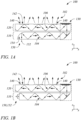
- Figure 1A illustrates a cross sectional view of a dual light guide, grating-based backlight 100 in an example, according to an embodiment consistent with the principles described herein.
- Figure 1B illustrates a cross sectional view of a dual light guide, grating-based backlight 100 in an example, according to another embodiment consistent with the principles described herein.
- the dual light guide, grating-based backlight 100 is configured to produce a plurality of light beams 102.
- the plurality of light beams 102 may correspond to information contained in pixels of an electronic display that employs the dual light guide, grating-based backlight 100, according to various examples and embodiments.
- the plurality of light beams 102 may form a light field in a viewing direction of an electronic display that employs the dual light guide, grating-based backlight 100.
- a light beam 102 of the plurality of light beams 102 (and within the light field) provided by the dual light guide, grating-based backlight 100 may be configured to have a different principal angular direction from other light beams 102 of the plurality.
- the light beam 102 may have both a predetermined direction (principal angular direction) and a relatively narrow angular spread within the light field.
- the principal angular direction of the light beam 102 may correspond to an angular direction of a particular view of the 3D electronic display.
- the light beam 102 may represent or correspond to a pixel of the 3D electronic display, according to some examples.
- light beams 102 of the plurality may have substantially similar predetermined principal angular directions (not illustrated in Figures 1A-1B ).
- the similarly directed light beams 102 generally do not form a light field, but instead represent light emitted by the dual light guide, grating-based backlight 100 that is substantially unidirectional (e.g., perpendicular to a surface of the dual light guide, grating-based backlight 100).
- the similarly directed light beams 102 may be used as a backlight for a two-dimensional (2D) electronic display, for example.
- the light beams 102 of the plurality produced by the dual light guide, grating-based backlight 100 may be modulated (e.g., by a light valve as described below).
- the modulation of the light beams 102 directed in different angular directions away from the dual light guide, grating-based backlight 100 may be particularly useful for dynamic 3D color electronic display applications, for example. That is, the individually modulated light beams 102 of different colors and directed in a particular view direction may represent dynamic color pixels of the 3D electronic display corresponding to the particular view direction.
- dynamic 2D electronic display applications may be supported when the light beams 102 are substantially unidirectional.
- the dual light guide, grating-based backlight 100 comprises a first plate light guide 110.
- the first plate light guide 110 is configured to guide light (e.g., from a light source described below) as a guided light beam 104.
- the guided light beam 104 is guided in a first direction (e.g., to the right as illustrated in Figures 1A and 1B ).
- the first plate light guide 110 is configured to guide the guided light beam 104 at a non-zero propagation angle, according to the invention.
- the first plate light guide 110 may include a dielectric material configured as an optical waveguide.
- the dielectric material may have a first refractive index that is greater than a second refractive index of a medium surrounding the dielectric optical waveguide.
- the difference in refractive indices is configured to facilitate total internal reflection of the guided light beam 104 according to one or more guided modes of the light guide 110, for example.
- the non-zero propagation angle is an angle relative to a surface (e.g., a top surface or a bottom surface) of the plate light guide 110.
- the non-zero propagation angle of the guided light beam 104 may be between about ten (10) degrees and about fifty (50) degrees or, in some examples, between about twenty (20) degrees and about forty (40) degrees, or between about twenty-five (25) degrees and about thirty-five (35) degrees.
- the non-zero propagation angle may be about thirty (30) degrees. In other examples, the non-zero propagation angle may be about 20 degrees, or about 25 degrees, or about 35 degrees.
- the light to be guided as the guided light beam 104 is introduced or coupled into the first plate light guide 110 at the non-zero propagation angle (e.g., about 30-35 degrees).
- the non-zero propagation angle e.g., about 30-35 degrees.
- a lens not illustrated
- a mirror or similar reflector e.g., a tilted collimating reflector
- a prism not illustrated
- the guided light beam 104 propagates along the first plate light guide 110 in the first direction that is generally away from the input end (e.g., illustrated by bold arrows pointing along an x-axis in Figures 1A-1B ).
- the guided light beam 104 propagates by reflecting or 'bouncing' between the top surface and the bottom surface of the plate light guide 110 at the non-zero propagation angle (e.g., illustrated by an extended, angled arrow representing a light ray of the guided light beam 104).
- the guided light beam 104 produced by coupling light into the plate light guide 110 may be collimated (e.g., may be a collimated light beam), according to some examples. Further, according to some examples, the guided light beam 104 may be collimated in a plane that is perpendicular to a plane of a surface of the first plate light guide 110.
- the first plate light guide 110 may be oriented in a horizontal plane having a top and bottom surface parallel to an x-y plane (e.g., as illustrated).
- the guided light beam 104 may be collimated or substantially collimated in a vertical plane (e.g., an x-z plane), for example.
- the first plate light guide 110 may be a wedge-shaped plate light guide 110.
- One of the top or bottom surface may be parallel to the x-y plane when the first plate light guide 110 is wedge-shaped, for example.
- the guided light beam 104 may also be collimated or substantially collimated in a horizontal direction (e.g., in the x-y plane).
- a 'collimated' light beam is defined as a beam of light in which rays of the light beam are substantially parallel to one another within the light beam (e.g., the guided light beam 104). Further, rays of light that diverge or are scattered from the collimated light beam are not considered to be part of the collimated light beam, by definition herein. Collimation of the light to produce the collimated guided light beam 104 may be provided by the lens or mirror (e.g., tilted collimating reflector, etc.) used to couple the light into the first plate light guide 110, according to various embodiments.
- the lens or mirror e.g., tilted collimating reflector, etc.
- the first plate light guide 110 is a slab or plate optical waveguide comprising an extended, substantially planar sheet of optically transparent, dielectric material.
- the substantially planar sheet of dielectric material is configured to guide the guided light beam 104 using total internal reflection.
- the optically transparent material of the first plate light guide 110 may comprise any of a variety of dielectric materials including, but not limited to, one or more of various types of glass (e.g., silica glass, alkali-aluminosilicate glass, borosilicate glass, etc.) and substantially optically transparent plastics or polymers (e.g., poly(methyl methacrylate) or ⁇ acrylic glass', polycarbonate, etc.).
- the first plate light guide 110 may further include a cladding layer on at least a portion of a surface (e.g., one or both of the top surface and the bottom surface) of the first plate light guide 110 (not illustrated).
- the cladding layer may be used to further facilitate total internal reflection, according to some examples.
- the dual light guide, grating-based backlight 100 illustrated in Figures 1A-1B further comprises a second plate light guide 120.
- the second light guide 120 is configured to receive and guide a redirected light beam 106 in a second direction (e.g., to the left as illustrated).
- the second direction may be substantially opposite to the first direction.
- the first plate light guide 110 and the second plate light guide 120 may be substantially parallel or co-planar to one another (e.g., stacked one on top of the other, as illustrated).
- the first direction may be in a positive x-direction
- the second direction may be in a negative x-direction, as illustrated in Figures 1A-1B , by way of example and not limitation.
- the second direction may be substantially perpendicular or at another angle relative to the first direction.
- the first direction may be in the x-direction and the second direction may be in a ⁇ -direction (not illustrated).
- the first direction may be a z-direction and the second direction may be in an x-y plane.
- the second direction may be substantially any direction other than the first direction, according to various embodiments.
- the second plate light guide 120 may be substantially similar to the first plate light guide 110.
- the second plate light guide 120 may be a slab or plate optical waveguide comprising an extended, substantially planar sheet of optically transparent, dielectric material configured to guide the redirected light beam 106 using total internal reflection, as is described above with respect to the first plate light guide 110.
- the second plate light guide 120 may further include a cladding layer on at least a portion of a surface (e.g., one or both of the top surface and the bottom surface) of the second plate light guide 120 (not illustrated) to further facilitate total internal reflection, also as described above.
- the dual light guide, grating-based backlight 100 further comprises a redirection coupler 130.
- the redirection coupler 130 is configured to redirect the guided light beam 104 of the first plate light guide 110 in a second direction as the redirected light beam 106.
- the redirected light beam 106 is then received and guided by the second plate light guide 120.
- the redirection coupler 130 substantially 'turns' the guided light beam 104 in a new or different direction the redirected light beam 106.
- the second direction of the redirected light beam 106 is different from the first direction and may be substantially opposite to the first direction of the guided light beam 104, as illustrated in Figure 1A-1B by way of example.
- the redirection coupler 130 may preserve or substantially preserve collimation of the guided light beam 104 within the redirected light beam 106.
- Figure 2A illustrates a cross sectional view of a redirection coupler 130 in an example, according to an embodiment consistent with the principles described herein.
- the redirection coupler 130 illustrated in Figure 2A is a corner reflector located at an output end of the first plate light guide 110 and at an input end of the second plate light guide 120.
- the corner reflector of the redirection coupler 130 may include a pair of mirrors 132 or equivalent reflectors (e.g., total internal reflection or 'TIR' mirror, a Bragg mirror, etc.) arranged at an angle to one another.
- a first mirror 132' of the corner reflector mirror pair 132 is positioned to reflect the guided light beam 104 from the first plate light guide 110 to a second mirror 132" of the corner reflector mirror pair 132.
- the second mirror 132" is positioned to further reflect the reflected light beam into the second plate light guide 120.
- the position of the second mirror 132" relative to the first mirror 132' is configured to reflect light at an angle different from the angle of reflection by the first mirror 132'.
- reflection at the second mirror 132" then provides the redirected light beam 106 (i.e., redirects the reflected light beam), which enters and is guided by the second plate light guide 120 in the second direction.
- the combined reflections at the first and second mirrors 132', 132" are configured to provide the redirected light beam 106 with a predetermined, non-zero propagation angle within the second plate light guide 120.
- a relationship between the non-zero propagation angle of the guided light beam 104 in the first plate light guide 110 and the predetermined, non-zero propagation angle of the redirected light beam 106 guided within the second plate light guide 120 is determined by both a relative orientation of the first and second mirrors 132', 132" to one another and an orientation of the corner reflector relative to the first and second plate light guides 110, 120, according to various embodiments.
- the pair of mirrors 132 of the corner reflector may be oriented at a ninety (90) degree angle to one another.
- the corner reflector is a retroreflector (i.e., a 90-degree corner reflector).
- the corner reflector of the redirection coupler 130 may be tilted relative to a plane of one or both of the first plate light guide 110 and the second plate light guide 120. The tilt of the corner reflector (or of the redirection coupler 130) is configured to provide the predetermined, non-zero propagation angle of the redirected light beam 106.
- a tilt of zero degrees produces a redirected light beam 106 having a predetermined, non-zero propagation angle that is equal to the non-zero propagation angle of the guided light beam 104, e.g., as illustrated in Figure 2A .
- the predetermined, non-zero propagation angle of the redirected light beam 106 may still be provided by an appropriate adjustment of an angular relationship between the corner reflector mirror pair 132 and the first and second plate light guides 110, 120, for example.
- the predetermined, non-zero propagation angle of the redirected light beam 106 may be readily determined for the various angular relationships between the mirrors 132', 132" themselves and between the pair of mirrors 132 and the plate light guides 110, 120 for a given the non-zero propagation angle of the guided light beam 104 using geometric optics.
- FIG. 2B illustrates a cross sectional view of a redirection coupler 130 in an example, according to another embodiment consistent with the principles described herein.
- the redirection coupler 130 comprises a tilted mirror 134 and a grating coupler 136.
- the mirror 134 has a tilt angle relative to a plane of or surface of the first plate light guide 110.
- the tilted mirror 134 is configured to reflect the guided light beam 104 from the first plate light guide 110 toward the grating coupler 136 as a reflected light beam 104'.
- the tilt angle of the tilted mirror 134 not only directs the reflected light beam 104' at the grating coupler 136, but also determines an angle of incidence of the reflected light beam 104' at the grating coupler 136.
- the grating coupler 136 comprises a diffraction grating configured to diffract the reflected light beam 104' received from the tilted mirror 134.
- the grating coupler 136 diffracts the reflected light beam 104' into the second direction as the redirected light beam 106 to be guided in the second plate light guide 120.
- a combination of the reflection by the tilted mirror 134 and the diffraction of the grating coupler 136 may provide the predetermined, non-zero propagation angle of the redirected light beam 106 within the second plate light guide 120.
- the diffraction by the grating coupler 136 is configured to determine the predetermined, non-zero propagation angle of the redirected light beam 106.
- the redirection coupler 130 further comprises a second mirror 138.
- the second mirror 138 is configured to reflect and redirect light of a secondary diffraction product of the grating coupler 136.
- the second mirror 138 is oriented to reflect and redirect the secondary diffraction product light into the second direction to augment the redirected light beam 106 within the second plate light guide 120.
- the redirected light beam 106 may correspond to light of a primary diffraction product (e.g., a positive, first order diffraction product).
- a solid line is used to denote light of the primary diffraction product (i.e., light beam 106) and a dashed line between the grating coupler 136 and the second mirror 138 denotes light of the secondary diffraction product.
- the second mirror 138 may be oriented to reflect and redirect the secondary diffraction product (e.g., a negative, first order diffraction product) in the second direction and at a non-zero propagation angle that is about equal to the predetermined, non-zero propagation angle of the redirected light beam 106 within the second plate light guide 120.
- a beam of light 106' dashed-line 106' in Figure 2B ) corresponding to the reflected and redirected secondary diffraction product will effectively add to or augment the redirected light beam 106 resulting in an improved efficiency of the redirection coupler 130 compared to embodiments without the second mirror 138, according to some embodiments.
- the tilted mirror 134 is configured reflect the guided light beam 104 of the first plate light guide 110 toward the grating coupler 136 to provide a substantially normal angle of incidence of the reflected light beam 104' at the grating coupler 136.
- the primary diffraction product of the diffraction grating of the grating coupler 136 may be the positive first order diffraction product, a diffraction angle of which corresponds to the predetermined, non-zero propagation angle of the redirected light beam 106.
- the second mirror 138 may be oriented at a ninety (90) degree angle to the grating coupler 136, as illustrated in Figure 2B .
- the secondary diffraction product may be a negative, first order diffraction product that has a 90-degree relationship to the primary diffraction product (i.e., the positive, first order diffraction product).
- the 90-degree oriented second mirror 138 is configured to reflect and redirect the secondary diffraction product as the light beam 106' in the second plate light guide 120 at substantially the same non-zero propagation angle as that of the redirected light beam 106. As such, the redirected light beam 106 is substantially augmented with the light beam 106' in the second plate light guide 120.
- the tilted mirror 134 may be virtually any mirror or equivalent reflector that reflects or substantially reflects the guided light beam 104 and further that is tilted at an angle configured to change a direction of the guided light beam 104.
- the tilted mirror 134 may comprise a metal or metalized surface (e.g., a silvered mirror).
- the tilted mirror 134 may be a Bragg mirror.
- the tilted mirror 134 be realized by total internal reflection (TIR) and be a TIR mirror.
- the tilted mirror 134 may be provided by a beveled surface of the first plate light guide 110 and TIR within the first plate light guide 110 in the vicinity of the beveled surface may serve as the tilted mirror 134.
- the second mirror 138 may be substantially any mirror or equivalent reflector including, but not limited to, a metal or metalized surface, a Bragg mirror and a TIR mirror.
- the second mirror 138 may be provided by metalizing an end of the second plate light guide 120.
- the end of the second plate light guide 120 is configured to provide TIR of the secondary diffraction product incident on the second plate light guide end as the second mirror 138.
- one or more of the mirrors described above may be a collimating mirror.
- one or both of the corner reflector mirrors 132', 132" may have a parabolic curved surface that provides collimation of the redirected light beam 106 (e.g., in a horizontal direction, a vertical direction or both).
- one or both of the tilted mirror 134 and the second mirror 138 may be a collimating mirror having a parabolic curved surface to collimate the reflected light beam 104' resulting in collimation (e.g., one or both of vertical and horizontal collimation) of the redirected light beam 106 (e.g., after diffraction by the grating coupler 136).
- the grating coupler 136 comprises diffractive features (e.g., grooves or ridges) spaced apart from one another to form a diffraction grating.
- the diffractive features may be either at, in or adjacent to a surface of the second plate light guide 120.
- the grating coupler 136 may comprise a plurality of grooves formed in a top surface of the second plate light guide 120 within the redirection coupler 130.
- the diffraction grating comprises uniform or substantially uniform spacing between the diffractive features. Further, a zero order diffraction product of the diffraction grating may be suppressed, according to various embodiments.
- the diffraction grating may have a diffractive feature height or depth (e.g., ridge height or groove depth) and a duty cycle selectively chosen to suppress the zero order diffraction product.
- the duty cycle may be between about thirty percent (30%) and about seventy percent (70%).
- the height or depth may range from greater than zero to about five hundred nanometers.
- the duty cycle may be about fifty (50) percent and the diffractive feature height or depth may be about one hundred forty (140) nanometers.
- the grating coupler 136 comprises a reflective diffraction grating such as, but not limited to, a reflective metal or metalized diffraction grating.
- Figure 2B illustrates the grating coupler 136 comprising diffractive features 136a as ridges on (or protruding from) the top surface of the second plate light guide 120. Further, spaces between and above the diffractive features 136a are filled by a layer 136b of a reflective material, such as a reflective metal.
- the reflective metal may include, but is not limited to, aluminum, nickel, silver or gold.
- Using a reflective diffraction grating may provide a higher diffraction efficiency compared to a dielectric diffraction grating (i.e., grooves or ridges in a dielectric material of the second plate light guide 120, for example).
- the dual light guide, grating-based backlight 100 further comprises a diffraction grating 140.
- the dual light guide, grating-based backlight 100 may comprise a plurality of diffraction gratings 140, according to some embodiments.
- the plurality of diffraction gratings 140 may be arranged as or represent an array of diffraction gratings 140, for example.
- the diffraction gratings 140 are located at a surface of the second plate light guide 120 (e.g., a top or front surface).
- one or more of the diffraction gratings 140 may be located within the second plate light guide 120. In yet other embodiments (not illustrated), one or more of the diffraction gratings 140 may be located at or on a bottom or back surface of the second plate light guide 120.
- the diffraction grating 140 is configured to scatter or couple out a portion of the redirected light beam 106 from the second plate light guide 120 by or using diffractive coupling (e.g., also referred to as 'diffractive scattering).
- the portion of the redirected light beam 106 may be diffractively coupled out by the diffraction grating 140 through the light guide surface (e.g., through the top or front surface of the second plate light guide 120).
- the diffraction grating 140 is configured to diffractively couple out the portion of the redirected light beam 106 as a coupled-out light beam (e.g., a light beam 102).
- the coupled-out light beam 102 is directed away from the light guide surface at a predetermined principal angular direction, according to various examples.
- the coupled-out portion of the redirected light beam 106 is diffractively redirected away from the light guide surface by the plurality of diffraction gratings 140 as the plurality of light beams 102.
- each of the light beams 102 of the light beam plurality may have a different principal angular direction and the light beam plurality may represent a light field, according to some examples.
- each of the light beams 102 of the light beam plurality may have substantially the same principal angular direction and the light beam plurality may represent substantially unidirectional light as opposed to the light field represented by the light beam plurality having light beams with different principal angular directions.
- the diffraction grating 140 comprises a plurality of diffractive features 142 that diffract light (i.e., provide diffraction).
- the diffraction is responsible for the diffractive coupling of the portion of the redirected light beam 106 out of the second plate light guide 120.
- the diffraction grating 140 may include one or both of grooves in a surface of the second plate light guide 120 and ridges protruding from the second light guide surface that serve as the diffractive features 142.
- the grooves and ridges may be arranged parallel or substantially parallel to one another and, at least at some point, perpendicular to a propagation direction of the redirected light beam 106 that is to be coupled out by the diffraction grating 140.
- the diffractive features may be etched, milled or molded into the surface or applied on the surface.
- a material of the diffraction grating 140 may include a material of the second plate light guide 120.
- the diffraction gratings 140 comprise substantially parallel grooves formed in the surface of the second plate light guide 120.
- the diffraction gratings 140 comprise substantially parallel ridges that protrude from the second light guide surface, for example.
- the diffraction gratings 140 may be implemented in or as a film or layer applied or affixed to the surface of the second light guide 120.
- the plurality of diffraction gratings 140 may be arranged in a variety of configurations with respect to the second plate light guide 120.
- the plurality of diffraction gratings 140 may be arranged in columns and rows across the light guide surface (e.g., as an array).
- a plurality of diffraction gratings 140 may be arranged in groups and the groups may be arranged in rows and columns.
- the plurality of diffraction gratings 140 may be distributed substantially randomly across the surface of the second plate light guide 120.
- the plurality of diffraction gratings 140 comprises a multibeam diffraction grating 140.
- all or substantially all of the diffraction gratings 140 of the plurality may be multibeam diffraction gratings 140 (i.e., a plurality of multibeam diffraction gratings 140).
- the multibeam diffraction grating 140 is a diffraction grating 140 that is configured to couple out the portion of the redirected light beam 106 as a plurality of light beams 102 (e.g., as illustrated in Figures 1A and 1B ), having different principal angular directions that forms a light field, according to various embodiments.
- the multibeam diffraction grating 140 may comprise a chirped diffraction grating 140 (i.e., a chirped multibeam diffraction grating).
- the 'chirped' diffraction grating 140 is a diffraction grating exhibiting or having a diffraction spacing of the diffractive features that varies across an extent or length of the chirped diffraction grating 140. Further herein, the varying diffraction spacing is defined as a 'chirp'.
- the redirected light beam 106 that is diffractively coupled out of the second plate light guide 120 exits or is emitted from the chirped diffraction grating 140 as the light beams 102 at different diffraction angles corresponding to different points of origin across the chirped diffraction grating 140.
- the chirped diffraction grating 140 is responsible for respective predetermined and different principal angular directions of the coupled-out light beams 102 of the light beam plurality.
- Figure 3A illustrates a cross sectional view of a portion of a dual light guide, grating-based backlight 100 including a multibeam diffraction grating 140 in an example, according to an embodiment consistent with the principles described herein.
- Figure 3B illustrates a perspective view of the dual light guide, grating-based backlight portion of Figure 3A including the multibeam diffraction grating 140 in an example, according to an embodiment consistent with the principles described herein.
- the multibeam diffraction grating 140 illustrated in Figure 3A comprises grooves in a surface of the second plate light guide 120, by way of example and not limitation.
- the multibeam diffraction grating 140 illustrated in Figure 3A may represent one of the groove-based diffraction gratings 140 illustrated in Figure 1A .
- the multibeam diffraction grating 140 is a chirped diffraction grating.
- the diffractive features 142 are closer together at a first end 140' of the multibeam diffraction grating 140 than at a second end 140".
- the diffractive spacing d of the illustrated diffractive features 142 varies linearly from the first end 140' to the second end 140".
- the chirped diffraction grating 140 may have or exhibit a chirp of the diffractive spacing d that varies linearly with distance.
- the chirped diffraction grating 140 may be referred to as a 'linearly chirped' diffraction grating.
- the light beams 102 produced by coupling light out of the second plate light guide 120 using the multibeam diffraction grating 140 may diverge (i.e., be diverging light beams 102) when the redirected light beam 106 propagates in the second plate light guide 120 in a direction from the first end 140' of the multibeam diffraction grating 140 to the second end 140" of the multibeam diffraction grating 140 (e.g., as illustrated in Figure 3A ).
- converging light beams 102 may be produced when the redirected light beam 106 propagates in the reverse direction in the second plate light guide 120, i.e., from the second end 140" to the first end 140' of the multibeam diffraction grating 140, according to other examples (not illustrated).
- the chirped diffraction grating 140 may exhibit a non-linear chirp of the diffractive spacing d .
- Various non-linear chirps that may be used to realize the chirped diffraction grating 140 include, but are not limited to, an exponential chirp, a logarithmic chirp or a chirp that varies in another, substantially non-uniform or random but still monotonic manner.
- Non-monotonic chirps such as, but not limited to, a sinusoidal chirp or a triangle or sawtooth chirp, may also be employed. Combinations of any of these types of chirps may also be used.
- the multibeam diffraction grating 140 includes diffractive features 142 (e.g., grooves or ridges) in, at or on a surface of the second plate light guide 120 that are both chirped and curved (i.e., the multibeam diffraction grating 140 is a curved, chirped diffraction grating).
- the redirected light beam 106 has an incident direction relative to the multibeam diffraction grating 140 and the second plate light guide 120, as illustrated by a bold arrow labeled '106' in Figures 3A-3B .
- the plurality of coupled-out or emitted light beams 102 pointing away from the multibeam diffraction grating 140 at the surface of the second plate light guide 120.
- the illustrated light beams 102 are emitted in a plurality of predetermined different principal angular directions.
- the predetermined different principal angular directions of the emitted light beams 102 are different in both azimuth and elevation (e.g., to form a light field), as illustrated.
- both the predefined chirp of the diffractive features 142 and the curve of the diffractive features 142 may be responsible for a respective plurality of predetermined different principal angular directions of the emitted light beams 102.
- the diffractive features 142 within the multibeam diffraction grating 140 may have varying orientations relative to an incident direction of the redirected light beam 106 guided in the second plate light guide 120.
- an orientation of the diffractive features 142 at a first point or location within the multibeam diffraction grating 140 may differ from an orientation of the diffractive features 142 at another point or location relative to the guided light beam incident direction.
- an azimuthal component ⁇ of the principal angular direction ⁇ ⁇ , ⁇ ⁇ of the light beam 102 may be determined by or correspond to the azimuthal orientation angle ⁇ ⁇ of the diffractive features 142 at a point of origin of the light beam 102 (i.e., at a point where the incident redirected light beam 106 is coupled out), according to some examples.
- the varying orientations of the diffractive features 142 within the multibeam diffraction grating 140 produce different light beams 102 having different principle angular directions ⁇ ⁇ , ⁇ ⁇ , at least in terms of their respective azimuthal components ⁇ .
- an 'underlying diffraction grating' of the multibeam diffraction grating 140 associated with the curved diffractive features 142 has different azimuthal orientation angles ⁇ ⁇ .
- 'underlying diffraction grating' it is meant that a diffraction grating of a plurality of non-curved diffraction gratings that in superposition yield the curved diffractive features of the multibeam diffraction grating 140.
- the curve has a particular azimuthal orientation angle ⁇ ⁇ that generally differs from the azimuthal orientation angle ⁇ ⁇ at another point along the curved diffractive features 142. Further, the particular azimuthal orientation angle ⁇ ⁇ results in a corresponding azimuthal component ⁇ of a principal angular direction ⁇ ⁇ , ⁇ ⁇ of a light beam 102 emitted from the given point.
- the curve of the diffractive features 142 e.g., grooves, ridges, etc.
- the curve may represent a section of an ellipse or another curved shape, e.g., that is coplanar with the light guide surface.
- the multibeam diffraction grating 140 may include diffractive features 142 that are 'piecewise' curved.
- the diffractive feature 142 may not describe a substantially smooth or continuous curve per se , at different points along the diffractive feature 142 within the multibeam diffraction grating 140, the diffractive feature 142 still may be oriented at different angles with respect to the incident direction of the redirected light beam 106.
- the diffractive feature 142 may be a groove including a plurality of substantially straight segments, each segment having a different orientation than an adjacent segment. Together, the different angles of the segments may approximate a curve (e.g., a segment of a circle), according to various embodiments.
- the diffractive features 142 may merely have different orientations relative to the incident direction of the guided light at different locations within the multibeam diffraction grating 140 without approximating a particular curve (e.g., a circle or an ellipse).
- the dual light guide, grating-based backlight 100 further comprises a light source 150, according to some embodiments.
- the light source 150 may be coupled to an input end of the first plate light guide 110 opposite to the output end adjacent to the redirection coupler 130, for example.
- the light source 150 includes a plurality of optical emitters 152.
- the optical emitters 152 are (or more generally the light source 150 is) configured to provide light to the first plate light guide 110 as the guided light 104, i.e., as the guided light beam 104.
- the provided light comprises a plurality of different colors of light that, when coupled into the plate light guide 110, is configured to be guided as a plurality of different color light beams 104, according to various embodiments.
- the plurality of optical emitters 152 is configured to produce the plurality of different colors of light.
- the guided light beams 104 of different colors are configured to be guided within the first plate light guide 110 at different, color-specific, non-zero propagation angles.
- a red guided light beam 104 may be coupled into and propagates within the first plate light guide 110 at a first non-zero propagation angle
- a green guided light beam 104 may be coupled into and propagates within the first plate light guide 110 at a second non-zero propagation angle
- a blue guided light beam 104 may be coupled into and propagates within the first plate light guide 110 at a third non-zero propagation angle.
- the respective first, second and third non-zero propagation angles are different from one another.
- the light source 150 may further comprise a tilted, shaped parabolic reflector 154.
- the different, color specific, non-zero propagation angles may be provided by respective red, green and blue optical emitters 152 of the optical emitter plurality laterally offset from one another (not separately illustrated in Figure 1A ) that feed or emit into the tilted, shaped parabolic reflector 154 at the input end of the first plate light guide 110, for example.
- the lateral offset of the different color emitters 152 in conjunction with the titled, shaped parabolic reflector 154 is configured to couple the different light colors (e.g., red light, green light, and blue light) into the first plate light guide 110 at corresponding different, color-specific, non-zero propagation angles, according to various embodiments.
- the different light colors e.g., red light, green light, and blue light
- the redirection coupler 130 may preserve or substantially preserve the color-specific, non-zero propagation angles when redirecting the different color guided light beams 104 into the second plate light guide 120 as redirected light beams 106 corresponding to the different colors.
- color-specific angular differences between the different color guided light beams 104 may be substantially preserved upon redirection.
- the redirection coupler 130 implemented as a retroreflector may preserve the color-specific, non-zero propagation angles of the different color guided light beams 104 in the corresponding different color redirected light beams 106.
- the redirection coupler 130 may adjust, augment or otherwise change one or more of the color specific, propagation angles and still maintain a difference therebetween upon redirection into the second plate light guide 120, according to other embodiments.
- the guided light beams 104 of different colors are configured to propagate within the first plate light guide 110 at similar or even about the same non-zero propagation angle.
- the redirection coupler 130 may be configured to provide different, color-specific, non-zero propagation angles to the redirected light beams 106 of different colors.
- the light source 150 may be configured to produce and introduce each of a red light, a green light and a blue light into first plate light guide 110 at substantially the same non-zero propagation angle (e.g., as opposed to different, color-specific, non-zero propagation angles).
- the redirection coupler 130 may comprise a grating coupler configured to redirect the guided light beams of red, green and blue colors in the second direction in the second plate light guide 120 at respective different, color-specific, non-zero propagation angles.
- the grating coupler may be substantially similar to the grating coupler 136 described above, for example.
- the redirection coupler 130 may further comprise a tilted mirror to reflect guided light beams of red, green and blue colors into the tilted mirror, as described above, for example.
- the light source 150 may comprise substantially any source of light including, but not limited to, a light emitting diode (LED) and a laser.
- the light source 150 may produce a substantially monochromatic light having a narrowband spectrum denoted by a particular color.
- the color may be or represent a primary color (e.g., of an electronic display).
- the light source 150 may produce a plurality of different colors of light representing a plurality of different primary colors.
- the primary colors may comprise red light, green light and blue light, for example.
- the primary colors may be primary colors of a color electronic display, wherein the primary colors are selected according to a color model such as, but not limited to, a red-green-blue (RGB) color model configured to support a color gamut of the color electronic display.
- a color model such as, but not limited to, a red-green-blue (RGB) color model configured to support a color gamut of the color electronic display.
- RGB red-green-blue
- the light source 150 may be a multicolor light source comprising a plurality of LEDs. LEDs of the plurality may represent different colors of the primary colors of the color electronic display, for example.
- the LEDs may comprise a red LED to produce red light, a green LED to produce green light, and a blue LED to produce blue light of the RGB color model, for example.
- the light source 150 may comprise a linear array of optical emitters 152 arranged along the input end of the first plate light guide 110. Each of the optical emitters may comprise a red LED, a green LED and blue LED, for example.
- the light source 150 may be configured to produce collimated light (e.g., using a collimating reflector or lens).
- the tilted, shaped-parabolic reflector 154 illustrated in Figure 1A may be configured to produce a collimated light beam 104 when coupling light from the optical emitters 152 into the first plate light guide 110.
- Substantially any collimator e.g., collimating lens, collimating reflector, etc.
- any collimator may be inserted between the light source 150 and the first plate light guide 110 in Figure 1A to provide a collimated light beam 104, according to various embodiments.
- a three-dimensional (3D) electronic display is provided.
- the 3D electronic display is configured to emit modulated light beams having different directions as pixels of the 3D electronic display.
- the 3D electronic display is configured to display 3D information (e.g., 3D images).
- the 3D electronic display is an autostereoscopic or glasses-free 3D electronic display.
- different ones of the modulated, differently directed, light beams may correspond to different 'views' associated with the 3D electronic display, according to various examples.
- the different views may provide a ⁇ glasses free' (e.g., autostereoscopic, holographic, etc.) representation of information being displayed by the 3D electronic display, for example.
- FIG. 4 illustrates a block diagram of a 3D electronic display 200 in an example, according to an embodiment consistent with the principles described herein.
- the 3D electronic display 200 may be used to present 3D information such as, but not limited to, 3D images.
- the 3D electronic display 200 illustrated in Figure 4 is configured to emit modulated light beams 202 in different principal angular directions representing pixels corresponding to the different views of the 3D electronic display 200.
- the modulated light beams 202 are illustrated as diverging (e.g., as opposed to converging) in Figure 4 , by way of example and not limitation.
- the light beams 202 may further represent different colors and the 3D electronic display 200 may be a 3D color electronic display.
- the 3D electronic display 200 illustrated in Figure 4 comprises a first light guide 210 and a second light guide 220 configured to guide light.
- the guided light in the second light guide 220 is a source of the light that becomes the modulated light beams 202 emitted by the 3D electronic display 200.
- the first light guide 210 may be a plate light guide and may be substantially similar to the first plate light guide 110 described above with respect to the dual light guide, grating-based backlight 100.
- the second light guide 220 may be a plate light guide and may be substantially similar to the second plate light guide 120 of dual light guide, grating-based backlight 100, also described above.
- first and second light guides 210, 220 may each be a slab optical waveguide comprising a planar sheet of dielectric material configured to guide light by total internal reflection.
- first light guide 210 and the second light guide 220 as plate light guides may be arranged substantially co-planar to one another (e.g., as illustrated above in Figures 1A-1B ).
- first light guide 210 and the second light guide 220 may comprise a strip light guide.
- first light guide 210 and the second light guide 220 may comprise a plurality of substantially parallel strip light guides arranged adjacent to one another to approximate a plate light guide and thus be considered a form of a 'plate' light guide, by definition herein.
- the adjacent strip light guides of this form of plate light guide may confine light within the respective strip light guides and substantially prevent leakage into adjacent strip light guides (i.e., unlike a substantially continuous slab of material of the 'true' plate light guide), for example.
- the guided light within each of the first and second light guides 210, 220 is configured to propagate at a non-zero propagation angle as a beam of light.
- the guided light may include a plurality of different color guided light beams.
- a guided light beam in one or both of the first light guide 210 and the second light guide 220 may be collimated (i.e., the light may be guided as collimated or substantially collimated beams of light), according to some embodiments.
- the first and second light guides 210, 220 may be configured to guide light as a collimated light beam at a non-zero propagation angle within the respective light guides 210, 220.
- the 3D electronic display 200 further comprises a redirection coupler 230.
- the redirection coupler 230 is configured to couple and redirect a guided light beam from the first light guide 210 into the second light guide 220.
- the redirection coupler 230 may be substantially similar to the redirection coupler 130 described above with respect to the dual light guide, grating-based backlight 100.
- the redirection coupler 230 may comprise a corner reflector (e.g., as illustrated in Figure 2A ).
- the redirection coupler 230 may comprise a tilted mirror and a reflective grating coupler (e.g., as illustrated in Figure 2B ).
- the tilted mirror and reflective grating coupler may be substantially similar to the tilted mirror 134 and grating coupler 136 of the redirection coupler 130, described above.
- the tilted mirror may be configured to reflect the guided light beam from the first light guide 210 toward the reflective grating coupler.
- the reflective grating coupler may be configured to diffract and redirect the reflected guided light beam received from the tilted mirror into the second light guide 220 as a redirected light beam to be guided within the second light guide 220.
- the 3D electronic display 200 illustrated in Figure 4 further comprises an array of multibeam diffraction gratings 240.
- the array of multibeam diffraction gratings 240 may be located in, on or at a surface of the second light guide 220, for example.
- a multibeam diffraction grating 240 of the array is configured to diffractively couple out a portion of the redirected light beam guided within the second light guide 210 as plurality of coupled-out light beams 204 having different principal angular directions representing or corresponding to different views of the 3D electronic display 200.
- the multibeam diffraction gratings 240 may be substantially similar to the multibeam diffraction gratings 140 of the dual light guide, grating-based backlight 100, described above.
- the array of multibeam diffraction gratings 240 may include a chirped diffraction grating.
- diffractive features (e.g., grooves, ridges, etc.) of the multibeam diffraction gratings 240 are curved diffractive features.
- the curved diffractive features may include ridges or grooves that are curved (i.e., continuously curved or piece-wise curved) and spacings between the curved diffractive features that vary as a function of distance across the multibeam diffraction gratings 240 of the array.
- the multibeam diffraction gratings 240 may be chirped diffraction gratings having curved diffractive features.
- the 3D electronic display 200 further includes a light valve array 250.
- the light valve array 250 includes a plurality of light valves configured to modulate the coupled-out light beams 204 of the light beam plurality.
- the light valves of the light valve array 250 modulate the coupled-out light beams 204 to provide the modulated light beams 202 that are or represent pixels of the 3D electronic display 200.
- different ones of the modulated light beams 202 may correspond to different views of the 3D electronic display 200.
- different types of light valves in the light valve array 250 may be employed including, but not limited to, one or more of liquid crystal (LC) light valves, electrowetting light valves and electrophoretic light valves. Dashed lines are used in Figure 4 to emphasize modulation of the light beams 202, by way of example.
- LC liquid crystal
- the 3D electronic display 200 may further comprise a light source 260, according to some embodiments.
- the light source 260 is optically coupled to an input end of the first light guide 210 opposite to an output end adjacent to the redirection coupler 230.
- the light source 260 is substantially similar to the light source 150 described above with respect to the dual light guide, grating-based backlight 100.
- the light source 260 may comprise a plurality of optical emitters (e.g., LEDs).
- the light source 260 may comprise the plurality of optical emitters (e.g., LEDs) arranged along the input end of the first light guide 210 to provide a corresponding plurality of guided light beams within the first light guide 210.
- the guided light beams of the plurality may be guided in substantially parallel bands across the first light guide 210 from the input end to the output end thereof.
- the optical emitters of the light source 260 may be arranged as a linear array, each optical emitter producing a different collimated guided light beam within the first light guide 210, for example.
- an optical length of the first light guide 210 in a propagation direction of the guided light beams is greater than a distance along the first light guide 210 at which the different guided light beams of the plurality spread by about one half of a spacing between individual ones of the substantially parallel bands.
- the first light guide optical length is long enough so that adjacent collimated guided light beams spread into one another.
- the light source 260 may be configured to produce different colors of light (i.e., is a color light source).
- the 3D electronic display 200 may be a 3D color electronic display 200, in some embodiments.
- the optical emitters of the plurality may comprise a first optical emitter configured to emit a first color of light (e.g., red light), a second optical emitter configured to emit a second color of light (e.g., green light), and a third optical emitter configured to emit a third color of light (e.g., blue light).
- the first optical emitter may be a red light emitting diode (LED)
- the second optical emitter may be a green LED
- the third optical emitter may be a blue LED, for example.
- the optical emitter may include each of a red LED, a green LED and a blue LED and thus be a multicolor optical emitter, for example.
- the redirection coupler 230 may comprise a grating coupler configured to reflect and redirect different color light beams into the second light guide 220 at different, color-specific, non-zero propagation angles. Further, the color-specific, propagation angles may be configured to produce coupled-out color light beams 204 from the multibeam diffraction grating 240 that form color-specific light fields configured to provide color pixels corresponding to different views of the 3D electronic display 200. According to various embodiments, the color-specific light fields may have substantially similar cone angles to one another and therefore produce color-specific pixels representing substantially similar 3D electronic display views to one another, albeit in the different colors.
- Figure 5 illustrates a flow chart of a method 300 of grating-based backlight operation in an example, according to an embodiment consistent with the principles described herein.
- the method 300 of grating-based backlight operation comprises guiding 310 light in a first plate light guide at a non-zero propagation angle as a guided light beam.
- the guided light beam is collimated.
- the first plate light guide is substantially similar to the first plate light guide 110, described above with respect to the dual light guide, grating-based backlight 100.
- the method 300 of grating-based backlight operation further comprises redirecting 320 the guided light beam using a redirection coupler into a second plate light guide as a redirected guided light beam.
- the second plate light guide is substantially similar to the second plate light guide 120 described above with respect to the dual light guide, grating-based backlight 100.
- redirecting 320 the guided light beam employs a redirection coupler that is substantially similar to the redirection coupler 130 of the dual light guide, grating-based backlight 100, described above.
- the redirection coupler may comprise a corner reflector or another means to redirect 320 the guided light beam from a first direction of propagation within the first plate light guide into a second direction of propagation of the second plate light guide.
- redirecting 320 the guided light beam comprises reflecting the guided light beam from the first plate light guide toward a grating coupler.
- Reflecting the guided light beam may employ a tilted mirror that is substantially similar to the tilted mirror 134 of the redirection coupler 130, described above.
- Redirecting 320 the guided light beam further comprises diffractively redirecting the reflected light beam into the second plate light guide as the redirected guided light beam using the grating coupler.
- the grating coupler may be substantially similar to the grating coupler 136 described above with respect to the dual light guide, grating-based backlight 100.
- redirecting 320 the guided light beam may further include redirecting a secondary diffraction product produced by the grating coupler using a second mirror or similar reflector (e.g., a second mirror such as, but not limited to, the second mirror 138, described above).
- a second mirror or similar reflector e.g., a second mirror such as, but not limited to, the second mirror 138, described above.
- the guided light beam may be a light beam of a plurality of different color light beams guided in the first plate light guide.
- guiding 310 light of the different color light beams comprises guiding each different color light beam at a different, color-specific, non-zero propagation angle.
- redirecting 320 the guided light beam where the light beam is the plurality of different color light beams comprises diffractively redirecting each different color light beam into the second plate light guide at a different, color-specific, non-zero propagation angle employing a grating coupler.
- the method 300 of grating-based backlight operation further includes diffractively coupling out 330 a portion of the redirected guided light using a diffraction grating at a surface of the second plate light guide. Diffractively coupling out 330 the redirected guided light portion is configured to produce a coupled-out light beam directed away from the second plate light guide at a predetermined principal angular direction.
- diffraction gratings are located at, in or on the surface of the second plate light guide.
- the diffraction gratings may be formed in the surface thereof as grooves, ridges, etc.
- the diffraction gratings may include a film on the second plate light guide surface.
- the diffraction gratings are substantially similar to the diffraction grating 140 described above with respect to the dual light guide, grating-based backlight 100.
- the diffraction grating may be a multibeam diffraction grating configured to produce a plurality of light beams from the diffractively coupled out 330 portions of the redirected guided light beam.
- the multibeam diffraction grating may be substantially similar to the multibeam diffraction grating 140 described above including, but not limited to, a chirped diffraction grating comprising one of curved grooves and curved ridges that are spaced apart from one another. In other examples, the diffraction grating is located elsewhere including, but not limited to, within the second plate light guide.
- the diffractively coupled out 330 portion of redirected guided light of the method 300 of grating-based backlight operation may produce a plurality of emitted (or coupled-out) light beams directed away from the surface of the second light guide.
- Each of the emitted light beams of the light beam plurality is directed away from the surface at a predetermined principal angular direction.
- an emitted light beam of the light beam plurality may have a different principal angular direction from other emitted light beams of the light beam plurality.
- the emitted light beams of the light beam plurality may correspond to pixels of an electronic display that employs the grating-based backlight.
- the plurality of coupled-out (or emitted) light beams may be directed away from the second plate light guide in a plurality of different principal angular directions corresponding to different views of a three-dimensional (3D) electronic display.
- the electronic display may be a 3D electronic display.
- the electronic display may be a 2D electronic display.
- the method 300 of grating-based backlight operation further comprises modulating 340 the emitted light beams of the light beam plurality using a plurality of light valves.
- the plurality of emitted light beams that is diffractively coupled out 330 is modulated 340 by passing through or otherwise interacting with a corresponding plurality of light valves.
- Modulated light beams emitted from the light valve plurality may form the pixels of the electronic display that employs the grating-based backlight (including the 3D electronic display), according to some embodiments.
- the modulated 340 light beams may provide a plurality of views of the 3D electronic display (e.g., a glasses-free, 3D electronic display).
- the plurality of light valves used in modulating 340 the plurality of emitted light beams is substantially similar to the light valve array 250 described above with respect to the 3D electronic display 200.
- the light valves may include liquid crystal light valves.
- the light valves may be another type of light valve including, but not limited to, an electrowetting light valve and an electrophoretic light valve. Modulating 340 may be applied on a color-specific basis, according to some embodiments (e.g., when color optical emitters are employed).
Claims (14)
- Rétroéclairage à base de réseau à double guide de lumière (100) comprenant :un premier guide de lumière à plaque (110) configuré pour guider un faisceau de lumière (104) dans une première direction et à un angle de propagation non nul ;un second guide de lumière (120) configuré pour recevoir et guider un faisceau de lumière redirigé (106) dans une seconde direction et à un angle de propagation non nul ;un coupleur de redirection (130) configuré pour rediriger le faisceau de lumière guidé du premier guide de lumière à plaque (110) dans le second guide de lumière à plaque (120) en tant que faisceau de lumière redirigé dans la seconde direction ; etcaractérisé par :un réseau de diffraction (140) configuré pour coupler par diffraction une partie du faisceau de lumière redirigé du second guide de lumière à plaque (120) sous la forme d'un faisceau de lumière couplé (102) dirigé loin d'une surface du second guide de lumière à plaque (120) dans une direction angulaire principale prédéterminée,où le coupleur de redirection (130) comprend un miroir incliné (134) et un coupleur à réseau (136), le miroir incliné (134) étant incliné par rapport à un plan ou à une surface du premier guide de lumière à plaque (110) et configuré pour réfléchir le faisceau de lumière guidé reçu du premier guide de lumière à plaque (110) vers le coupleur à réseau (136),le coupleur à réseau étant configuré pour diffracter le faisceau de lumière réfléchi par le miroir incliné (134) dans la seconde direction, en tant que faisceau de lumière redirigé devant être guidé dans le second guide de lumière à plaque (120).
- Rétroéclairage à base de réseau à double guide de lumière selon la revendication 1, dans lequel le premier guide de lumière à plaque et le second guide de lumière à plaque sont sensiblement parallèles l'un à l'autre, et où la première direction du faisceau de lumière guidé est sensiblement opposée à la seconde direction du faisceau de lumière redirigé.
- Rétroéclairage à base de réseau à double guide de lumière selon la revendication 1, dans lequel le coupleur de redirection comprend en outre un second miroir (134) configuré pour réfléchir et rediriger la lumière d'un produit de diffraction secondaire provenant du coupleur à réseau dans la seconde direction afin d'augmenter le faisceau de lumière redirigé à l'intérieur du second guide de lumière à plaque.
- Rétroéclairage à base de réseau à double guide de lumière selon la revendication 1, dans lequel le coupleur à réseau comprend un réseau de diffraction réfléchissant.
- Rétroéclairage à base de réseau à double guide de lumière selon la revendication 1, dans lequel le réseau de diffraction comprend un réseau de diffraction à faisceaux multiples configuré pour coupler la partie du faisceau de lumière redirigé sous la forme d'une pluralité de faisceaux de lumière couplés, un faisceau de lumière de la pluralité de faisceaux de lumière couplés ayant une direction angulaire principale différente des autres faisceaux de lumière de la pluralité de faisceaux de lumière couplés pour former un champ de lumière configuré pour fournir des pixels correspondant à différentes vues d'un affichage électronique tridimensionnel, 3D.
- Rétroéclairage à base de réseau à double guide de lumière selon la revendication 5, dans lequel le réseau de diffraction à faisceaux multiples est un, ou les deux, des réseaux suivants : un réseau de diffraction comprimé de manière linéaire ou un réseau de diffraction comprimé comprenant des rainures incurvées ou des crêtes incurvées qui sont espacées les unes des autres.
- Rétroéclairage à base de réseau à double guide de lumière selon la revendication 1, comprenant en outre une source de lumière (150) couplée à une extrémité d'entrée du premier guide de lumière à plaque opposée à une extrémité de sortie adjacente au coupleur de redirection, la source de lumière fournissant une pluralité de couleurs de lumière différentes à guider sous la forme d'une pluralité de faisceaux de lumière de couleurs différentes.
- Rétroéclairage à base de réseau à double guide de lumière selon la revendication 7, dans lequel les différents faisceaux de lumière de couleur sont guidés à l'intérieur du premier guide de lumière à plaque à différents angles de propagation non nuls, spécifiques à la couleur.
- Rétroéclairage à base de réseau à double guide de lumière selon la revendication 7, dans lequel le coupleur de redirection comprend un coupleur à réseau configuré pour rediriger les différents faisceaux de lumière de couleur dans la seconde direction, chacun des faisceaux de lumière de différentes couleurs étant redirigé suivant un angle de propagation différent, spécifique à la couleur et non nul, dans le second guide de lumière à plaque par le coupleur à réseau.
- Écran d'affichage électronique tridimensionnel, 3D, (200) comprenant le rétroéclairage à base de réseau à double guide de lumière selon la revendication 1, où :
le réseau de diffraction fait partie d'un ensemble de réseaux de diffraction à faisceaux multiples (240) à une surface du second guide de lumière, chaque réseau de diffraction à faisceaux multiples de l'ensemble étant configuré pour coupler par diffraction une partie du faisceau de lumière redirigé à l'intérieur du second guide de lumière sous la forme d'une pluralité de faisceaux de lumière couplés ayant différentes directions angulaires principales représentant différentes vues de l'affichage électronique 3D ; et où l'affichage électronique 3D comprend en outre :
un réseau de modulateurs de lumière (250) configuré pour moduler les faisceaux de lumière couplés, les faisceaux de lumière couplés modulés représentant les pixels correspondant aux différentes vues. - Affichage électronique 3D selon la revendication 10, comprenant en outre une source de lumière (260) couplée optiquement à une extrémité d'entrée du premier guide de lumière opposée à une extrémité de sortie du premier guide de lumière adjacente au coupleur de redirection, la source de lumière comprenant une pluralité d'émetteurs optiques disposés le long de l'extrémité d'entrée du premier guide de lumière pour fournir une pluralité correspondante de faisceaux de lumière guidés dans des bandes sensiblement parallèles par le premier guide de lumière.
- Affichage électronique 3D selon la revendication 11, dans lequel une longueur optique du premier guide de lumière dans une direction de propagation des faisceaux de lumière guidés est supérieure à une distance le long du premier guide de lumière à laquelle les faisceaux de lumière guidés de la pluralité de faisceaux se diffusent d'environ la moitié d'un espacement entre des bandes individuelles des bandes sensiblement parallèles.
- Procédé (300) de rétroéclairage à base de réseau à double guide de lumière, le procédé comprenant les étapes suivantes :guider la lumière dans un premier guide de lumière à plaque (310) dans une première direction à un angle de propagation non nul sous la forme d'un faisceau de lumière guidé, le faisceau de lumière guidé étant collimaté ;rediriger le faisceau de lumière guidé à l'aide d'un coupleur de redirection (320) dans un second guide de lumière à plaque sous la forme d'un faisceau de lumière guidé redirigé dans une seconde direction à un angle de propagation non nul, où la redirection du faisceau de lumière guidé comprend les étapes suivantes :réfléchir le faisceau de lumière guidé depuis le premier guide de lumière à plaque vers un coupleur à réseau à l'aide d'un miroir incliné qui est incliné par rapport à la première direction ; etrediriger par diffraction le faisceau de lumière réfléchi dans le second guide de lumière à plaque sous forme de faisceau de lumière guidé redirigé à l'aide du coupleur à réseau ; etcoupler par diffraction une partie du faisceau de lumière guidé redirigé à l'aide d'un réseau de diffraction (330) sur une surface du second guide de lumière à plaque pour produire un faisceau de lumière couplé dirigé loin du second guide de lumière à plaque dans une direction angulaire principale prédéterminée.
- Procédé selon la revendication 13, dans lequel l'étape de redirection du faisceau de lumière guidé dans le second guide de lumière à plaque sous forme de faisceau de lumière guidé redirigé comprend en outre l'étape suivante :
réfléchir et rediriger la lumière d'un produit de diffraction secondaire provenant du coupleur à réseau pour augmenter le faisceau de lumière redirigé à l'intérieur du second guide de lumière à plaque.
Applications Claiming Priority (1)
| Application Number | Priority Date | Filing Date | Title |
|---|---|---|---|
| PCT/US2015/027399 WO2016171705A1 (fr) | 2015-04-23 | 2015-04-23 | Rétroéclairage à base de réseau de diffraction à guide de lumière double et dispositif d'affichage électronique l'utilisant |
Publications (4)
| Publication Number | Publication Date |
|---|---|
| EP3292432A1 EP3292432A1 (fr) | 2018-03-14 |
| EP3292432A4 EP3292432A4 (fr) | 2018-12-05 |
| EP3292432C0 EP3292432C0 (fr) | 2023-06-28 |
| EP3292432B1 true EP3292432B1 (fr) | 2023-06-28 |
Family
ID=57144147
Family Applications (1)
| Application Number | Title | Priority Date | Filing Date |
|---|---|---|---|
| EP15890106.6A Active EP3292432B1 (fr) | 2015-04-23 | 2015-04-23 | Rétroéclairage à base de réseau de diffraction à guide de lumière double et dispositif d'affichage électronique l'utilisant |
Country Status (8)
| Country | Link |
|---|---|
| US (1) | US10788619B2 (fr) |
| EP (1) | EP3292432B1 (fr) |
| JP (1) | JP6961491B2 (fr) |
| KR (1) | KR102329108B1 (fr) |
| CN (1) | CN107533255A (fr) |
| ES (1) | ES2956682T3 (fr) |
| TW (1) | TWI620972B (fr) |
| WO (1) | WO2016171705A1 (fr) |
Families Citing this family (67)
| Publication number | Priority date | Publication date | Assignee | Title |
|---|---|---|---|---|
| US11249239B2 (en) * | 2019-03-29 | 2022-02-15 | Ideal Industries Lighting Llc | Waveguide managing high power density |
| US11655950B2 (en) | 2014-03-15 | 2023-05-23 | Ideal Industries Lighting Llc | Lighting devices having optical waveguides for controlled light distribution |
| EP3062142B1 (fr) | 2015-02-26 | 2018-10-03 | Nokia Technologies OY | Appareil pour un dispositif d'affichage proche |
| CA2990591C (fr) | 2015-03-30 | 2021-12-21 | Leia Inc. | Affichage electronique commutable entre modes 2d/3d a retroeclairage a deux couches |
| FR3046850B1 (fr) * | 2016-01-15 | 2018-01-26 | Universite De Strasbourg | Guide optique ameliore et systeme optique comportant un tel guide optique |
| WO2018029042A1 (fr) * | 2016-08-10 | 2018-02-15 | Philips Lighting Holding B.V. | Luminaire indirect |
| CN106443867A (zh) * | 2016-11-09 | 2017-02-22 | 苏州苏大维格光电科技股份有限公司 | 一种波导器件及三维显示装置 |
| US10650552B2 (en) | 2016-12-29 | 2020-05-12 | Magic Leap, Inc. | Systems and methods for augmented reality |
| EP4300160A2 (fr) | 2016-12-30 | 2024-01-03 | Magic Leap, Inc. | Appareil de découplage de lumière polychromatique, affichages proches de l' il le comprenant, et procédé de découplage de lumière polychromatique |
| WO2018128657A1 (fr) | 2017-01-06 | 2018-07-12 | Leia Inc. | Affichage multivues statique et procédé |
| JP7153666B2 (ja) * | 2017-04-04 | 2022-10-14 | レイア、インコーポレイテッド | 多層マルチビューディスプレイおよび方法 |
| JP6922067B2 (ja) * | 2017-07-21 | 2021-08-18 | レイア、インコーポレイテッドLeia Inc. | マイクロレンズを備えるマルチビーム要素ベースのバックライトおよびそれを使用したディスプレイ |
| CN107238974B (zh) * | 2017-07-24 | 2021-03-02 | 京东方科技集团股份有限公司 | 一种背光源及液晶显示模组 |
| US10578870B2 (en) | 2017-07-26 | 2020-03-03 | Magic Leap, Inc. | Exit pupil expander |
| EP3688370A4 (fr) | 2017-09-27 | 2021-04-28 | LEIA Inc. | Dispositif d'affichage multi-vues statique multicolore et procédé associé |
| KR20200040928A (ko) | 2017-09-28 | 2020-04-20 | 레이아 인코포레이티드 | 집광을 이용하는 격자-결합 도광체, 디스플레이 시스템, 및 방법 |
| CN108227067B (zh) * | 2017-11-13 | 2021-02-02 | 南京矽力微电子技术有限公司 | 一种光学结构以及具有该光学结构的电子设备 |
| US11280937B2 (en) | 2017-12-10 | 2022-03-22 | Magic Leap, Inc. | Anti-reflective coatings on optical waveguides |
| CN108089253B (zh) | 2017-12-15 | 2019-06-25 | 京东方科技集团股份有限公司 | 光线准直装置、背光模组及显示装置 |
| CA3084793C (fr) | 2017-12-18 | 2022-08-30 | Leia Inc. | Retroeclairage a mode commutable, dispositif d'affichage, et procede |
| WO2019126331A1 (fr) | 2017-12-20 | 2019-06-27 | Magic Leap, Inc. | Insert pour dispositif de visualisation à réalité augmentée |
| JP7011066B2 (ja) | 2017-12-21 | 2022-02-10 | レイア、インコーポレイテッド | モード選択可能なバックライト、プライバシーディスプレイ、および方法 |
| CN115493480A (zh) | 2018-01-16 | 2022-12-20 | 太平洋灯光全息图公司 | 使用电磁场计算的三维显示方法、显示屏及系统 |
| CN110058347B (zh) * | 2018-01-18 | 2020-05-12 | 京东方科技集团股份有限公司 | 光源模组和电子装置 |
| EP3743656A4 (fr) | 2018-01-27 | 2021-12-01 | LEIA Inc. | Rétroéclairage à recyclage de polarisation, procédé et afficheur multi-vues faisant appel à des réseaux de sous-longueur d'onde |
| US10755676B2 (en) | 2018-03-15 | 2020-08-25 | Magic Leap, Inc. | Image correction due to deformation of components of a viewing device |
| US10761256B2 (en) * | 2018-04-16 | 2020-09-01 | Samsung Electronics Co., Ltd. | Backlight unit providing uniform light and display apparatus including the same |
| JP7319303B2 (ja) | 2018-05-31 | 2023-08-01 | マジック リープ, インコーポレイテッド | レーダ頭部姿勢位置特定 |
| KR20210024556A (ko) * | 2018-06-21 | 2021-03-05 | 바라자 피티와이 엘티디 | 광학 빔 지향기 |
| JP7284195B2 (ja) | 2018-06-29 | 2023-05-30 | レイア、インコーポレイテッド | 混合フォーマットバックライト、ディスプレイ、および方法 |
| CN108646338B (zh) * | 2018-07-02 | 2019-12-31 | 京东方科技集团股份有限公司 | 一种背光模组及显示装置 |
| US11579441B2 (en) | 2018-07-02 | 2023-02-14 | Magic Leap, Inc. | Pixel intensity modulation using modifying gain values |
| US11856479B2 (en) | 2018-07-03 | 2023-12-26 | Magic Leap, Inc. | Systems and methods for virtual and augmented reality along a route with markers |
| WO2020010226A1 (fr) | 2018-07-03 | 2020-01-09 | Magic Leap, Inc. | Systèmes et procédés pour des applications de réalité virtuelle et de réalité augmentée |
| US10545275B1 (en) * | 2018-07-16 | 2020-01-28 | Shenzhen Guangjian Technology Co., Ltd. | Light projecting method and device |
| US10690752B2 (en) | 2018-07-16 | 2020-06-23 | Shenzhen Guangjian Technology Co., Ltd. | Light projecting method and device |
| US10641942B2 (en) | 2018-07-16 | 2020-05-05 | Shenzhen Guangjian Technology Co., Ltd. | Light projecting method and device |
| JP7426982B2 (ja) | 2018-07-24 | 2024-02-02 | マジック リープ, インコーポレイテッド | 移動検出デバイスの温度依存較正 |
| WO2020023543A1 (fr) | 2018-07-24 | 2020-01-30 | Magic Leap, Inc. | Dispositif de visualisation à intégrant un joint anti-poussière |
| CN112740665A (zh) | 2018-08-02 | 2021-04-30 | 奇跃公司 | 基于头部运动的瞳孔间距离补偿的观察系统 |
| CN116820239A (zh) | 2018-08-03 | 2023-09-29 | 奇跃公司 | 图腾在用户交互系统中的融合姿势的基于未融合姿势的漂移校正 |
| EP3837579A4 (fr) * | 2018-08-13 | 2022-03-23 | LEIA Inc. | Collimateur de réseau, système de rétroéclairage et procédé utilisant une source de lumière de recyclage de lumière |
| CN108845460B (zh) * | 2018-08-15 | 2021-01-29 | 京东方科技集团股份有限公司 | 一种背光模组及显示装置 |
| US11506828B2 (en) * | 2018-08-24 | 2022-11-22 | Seereal Technologies S.A. | Light guide device and illumination device having a light guide device |
| KR102581313B1 (ko) * | 2018-10-01 | 2023-09-22 | 레이아 인코포레이티드 | 멀티뷰 픽셀들 및 멀티빔 방출기들의 오프셋된 행들을 갖는 멀티뷰 디스플레이 및 방법 |
| US10690846B2 (en) | 2018-10-24 | 2020-06-23 | Shenzhen Guangjian Technology Co., Ltd. | Light projecting method and device |
| US10914949B2 (en) | 2018-11-16 | 2021-02-09 | Magic Leap, Inc. | Image size triggered clarification to maintain image sharpness |
| US10585194B1 (en) | 2019-01-15 | 2020-03-10 | Shenzhen Guangjian Technology Co., Ltd. | Switchable diffuser projection systems and methods |
| US10564521B1 (en) | 2019-01-15 | 2020-02-18 | Shenzhen Guangjian Technology Co., Ltd. | Switchable diffuser projection systems and methods |
| CN111323931B (zh) | 2019-01-15 | 2023-04-14 | 深圳市光鉴科技有限公司 | 光投射系统和方法 |
| US10585173B1 (en) | 2019-01-15 | 2020-03-10 | Shenzhen Guangjian Technology Co., Ltd. | Systems and methods for enhanced ToF resolution |
| CN110149510B (zh) | 2019-01-17 | 2023-09-08 | 深圳市光鉴科技有限公司 | 用于屏下的3d摄像头模组及电子设备 |
| JP7270050B2 (ja) * | 2019-02-16 | 2023-05-09 | レイア、インコーポレイテッド | 光制御フィルムを有するマルチビューディスプレイ及び方法 |
| EP3939030A4 (fr) | 2019-03-12 | 2022-11-30 | Magic Leap, Inc. | Enregistrement d'un contenu local entre des premier et second visualiseurs de réalité augmentée |
| CN109856861B (zh) | 2019-04-02 | 2021-04-16 | 京东方科技集团股份有限公司 | 一种显示面板、显示装置,以及显示面板的驱动方法 |
| US11137534B2 (en) | 2019-06-26 | 2021-10-05 | Synaptics Incorporated | Systems and methods for optical imaging based on diffraction gratings |
| CN114174895A (zh) | 2019-07-26 | 2022-03-11 | 奇跃公司 | 用于增强现实的系统和方法 |
| WO2021040683A1 (fr) * | 2019-08-25 | 2021-03-04 | Leia Inc. | Élément de diffusion de rétroéclairage, dispositif d'affichage à vues multiples et procédé ayant une couche de guidage de lumière à indice élevé |
| JP2023502927A (ja) | 2019-11-15 | 2023-01-26 | マジック リープ, インコーポレイテッド | 外科手術環境において使用するための視認システム |
| CN111273486B (zh) * | 2020-03-25 | 2022-05-13 | 京东方科技集团股份有限公司 | 光线准直装置、背光模组以及显示面板 |
| US11360429B2 (en) | 2020-09-17 | 2022-06-14 | Pacific Light & Hologram, Inc. | Reconstructing objects with display zero order light suppression |
| WO2023025149A1 (fr) * | 2021-08-23 | 2023-03-02 | 未来(北京)黑科技有限公司 | Dispositif de guidage de lumière, dispositif de source de lumière, système d'affichage et véhicule de transport |
| CN114333612B (zh) * | 2021-11-24 | 2024-04-02 | 石家庄市京华电子实业有限公司 | 一种基于光栅透镜的微小间距led显示屏模组 |
| WO2023107104A1 (fr) * | 2021-12-07 | 2023-06-15 | Leia Inc. | Système de rétroéclairage, système d'affichage et procédé |
| TW202346937A (zh) * | 2022-04-03 | 2023-12-01 | 以色列商魯姆斯有限公司 | 採用與光導集成的二向色組合器的顯示器 |
| JP2024012992A (ja) * | 2022-07-19 | 2024-01-31 | 株式会社ジャパンディスプレイ | 表示装置 |
| US11900842B1 (en) | 2023-05-12 | 2024-02-13 | Pacific Light & Hologram, Inc. | Irregular devices |
Family Cites Families (130)
| Publication number | Priority date | Publication date | Assignee | Title |
|---|---|---|---|---|
| GB2269697A (en) | 1992-08-11 | 1994-02-16 | Sharp Kk | Display device |
| JP2979951B2 (ja) | 1994-04-18 | 1999-11-22 | 凸版印刷株式会社 | 回折格子パターンを有するディスプレイ |
| JP3528994B2 (ja) | 1994-11-08 | 2004-05-24 | 大日本印刷株式会社 | 液晶表示装置用平行光源及びそれを用いた液晶表示装置 |
| JPH10508151A (ja) | 1995-08-23 | 1998-08-04 | フィリップス エレクトロニクス ネムローゼ フェンノートシャップ | 扁平−パネル形画像表示デバイス |
| JP3336200B2 (ja) | 1995-12-12 | 2002-10-21 | シャープ株式会社 | 要素ホログラムパネルを有する3次元像表示装置 |
| US5721598A (en) | 1995-12-26 | 1998-02-24 | Hughes Electronics | High efficiency, high color purity, on-axis holographic color filter and full-color liquid crystal display |
| US7215451B1 (en) | 1996-04-15 | 2007-05-08 | Dai Nippon Printing Co., Ltd. | Reflection type diffuse hologram, hologram for reflection hologram color filters, etc., and reflection type display device using such holograms |
| US5913594A (en) * | 1997-02-25 | 1999-06-22 | Iimura; Keiji | Flat panel light source device and passive display device utilizing the light source device |
| WO1999008257A1 (fr) | 1997-08-05 | 1999-02-18 | Allan John Davie | Dispositif d'affichage commande par cristaux liquides |
| JPH11142863A (ja) | 1997-11-13 | 1999-05-28 | Nec Corp | 液晶表示パネルおよびその製造方法 |
| US6271970B1 (en) * | 1997-12-13 | 2001-08-07 | Lightchip, Inc. | Wavelength division multiplexing/demultiplexing devices using dual homogeneous refractive index lenses |
| JPH11184387A (ja) * | 1997-12-24 | 1999-07-09 | Seiko Instruments Inc | フロントライト型照明装置およびフロントライト型照明装置付き反射型カラー表示装置 |
| WO1999052002A1 (fr) | 1998-04-02 | 1999-10-14 | Elop Electro-Optics Industries Ltd. | Dispositifs optiques holographiques |
| CN1213097A (zh) | 1998-10-29 | 1999-04-07 | 厦门大学 | 制作医学影像诊断用的断层组合三维全息显示装置 |
| FI106323B (fi) | 1998-12-30 | 2001-01-15 | Nokia Mobile Phones Ltd | Taustavalaistuksen valonjohdin litteälle näytölle |
| JP2000267041A (ja) | 1999-03-16 | 2000-09-29 | Fuji Xerox Co Ltd | 頭部搭載型カラー映像投影装置、カラーホログラム光学素子、およびカラーホログラム光学素子の製造方法 |
| FI107085B (fi) | 1999-05-28 | 2001-05-31 | Ics Intelligent Control System | Valopaneeli |
| JP4006918B2 (ja) | 2000-02-28 | 2007-11-14 | オムロン株式会社 | 面光源装置及びその製造方法 |
| US6324330B1 (en) * | 2000-07-10 | 2001-11-27 | Ultratech Stepper, Inc. | Folded light tunnel apparatus and method |
| JP2002031788A (ja) | 2000-07-18 | 2002-01-31 | Sony Corp | 光学装置 |
| US6919950B2 (en) | 2000-08-29 | 2005-07-19 | Roman S. Dabrowski | Liquid crystal device and a liquid crystal material |
| US6490393B1 (en) | 2000-11-27 | 2002-12-03 | Advanced Interfaces, Llc | Integrated optical multiplexer and demultiplexer for wavelength division transmission of information |
| EP1397610B1 (fr) | 2001-06-01 | 2007-12-12 | Philips Lumileds Lighting Company LLC | Systeme d'eclairage compact et dispositif d'affichage |
| CN100440004C (zh) | 2001-09-28 | 2008-12-03 | 西铁城控股株式会社 | 液晶显示装置 |
| DE10210866C5 (de) | 2002-03-12 | 2008-04-10 | Mtu Aero Engines Gmbh | Leitschaufelbefestigung in einem Strömungskanal einer Fluggasturbine |
| US7027671B2 (en) * | 2002-03-18 | 2006-04-11 | Koninklijke Philips Electronics N.V. | Polarized-light-emitting waveguide, illumination arrangement and display device comprising such |
| GB0210568D0 (en) | 2002-05-08 | 2002-06-19 | Screen Technology Ltd | Display |
| JP3742038B2 (ja) | 2002-08-01 | 2006-02-01 | Nec液晶テクノロジー株式会社 | 液晶表示装置およびその製造方法 |
| JP2004077897A (ja) | 2002-08-20 | 2004-03-11 | Nippon Telegr & Teleph Corp <Ntt> | 表示装置 |
| JP4153776B2 (ja) * | 2002-11-07 | 2008-09-24 | 三菱電機株式会社 | 面状光源装置および該装置を用いた液晶表示装置 |
| KR100624408B1 (ko) | 2003-01-07 | 2006-09-18 | 삼성전자주식회사 | 백라이트 유닛 |
| US7184625B2 (en) | 2003-02-11 | 2007-02-27 | Luxtera, Inc | Optical waveguide grating coupler incorporating reflective optical elements and anti-reflection elements |
| JP2004302186A (ja) | 2003-03-31 | 2004-10-28 | Mitsubishi Electric Corp | 携帯情報端末 |
| TWI257490B (en) | 2003-07-09 | 2006-07-01 | Hon Hai Prec Ind Co Ltd | A light guide plate and a method of manufacturing the same |
| US20070201234A1 (en) * | 2003-07-21 | 2007-08-30 | Clemens Ottermann | Luminous element |
| JP2005062692A (ja) | 2003-08-19 | 2005-03-10 | Internatl Business Mach Corp <Ibm> | カラー表示装置、光学素子、およびカラー表示装置の製造方法 |
| CN1619373A (zh) | 2003-11-17 | 2005-05-25 | 鸿富锦精密工业(深圳)有限公司 | 导光板及背光模组 |
| US7369584B2 (en) | 2003-12-31 | 2008-05-06 | Symbol Technologies, Inc. | Laser projection display |
| US8723779B2 (en) | 2004-01-26 | 2014-05-13 | Mcmaster University | Tiled optical fiber display |
| EP3462227A3 (fr) * | 2004-03-29 | 2019-06-19 | Sony Corporation | Dispositif optique et dispositif d'affichage d'images virtuelles |
| TWI254166B (en) | 2004-05-25 | 2006-05-01 | Au Optronics Corp | 3D display system and method |
| DE602005023300D1 (de) | 2004-05-26 | 2010-10-14 | Tibor Balogh | Verfahren und vorrichtung zur erzeugung von 3d-bildern |
| EP1805549B1 (fr) | 2004-10-13 | 2013-04-10 | Koninklijke Philips Electronics N.V. | Appareil d'affichage stereoscopique |
| US7171080B2 (en) | 2004-11-15 | 2007-01-30 | Seagate Technology Llc | Coupling grating for focusing light within a waveguide for heat assisted magnetic recording |
| US7773849B2 (en) | 2004-12-14 | 2010-08-10 | Oms Displays Ltd. | Device and method for optical resizing and backlighting |
| KR100774061B1 (ko) * | 2005-05-17 | 2007-11-06 | 엔이씨 엘씨디 테크놀로지스, 엘티디. | 백라이트 및 액정 표시 장치 |
| CN1932602A (zh) | 2005-09-14 | 2007-03-21 | 鸿富锦精密工业(深圳)有限公司 | 导光板 |
| WO2007042852A1 (fr) | 2005-10-13 | 2007-04-19 | Nokia Corporation | Procede d'eclairage destine a afficher des dispositions graphiques differentes |
| JP2007145158A (ja) | 2005-11-28 | 2007-06-14 | Fujitsu Ten Ltd | 車載用表示装置及びその表示制御方法 |
| JP2007163294A (ja) | 2005-12-14 | 2007-06-28 | Sony Corp | 腕時計、腕時計の表示方法、および、プログラム |
| JP4600269B2 (ja) | 2005-12-21 | 2010-12-15 | カシオ計算機株式会社 | 液晶表示装置 |
| WO2007071794A2 (fr) | 2005-12-22 | 2007-06-28 | Universite Jean-Monnet | Structure miroir et dispositif laser comprenant une telle structure miroir |
| US20090303708A1 (en) * | 2006-04-21 | 2009-12-10 | Koninklijke Philips Electronics N V | Illumination System |
| JP4990275B2 (ja) | 2006-05-18 | 2012-08-01 | パナソニック株式会社 | 面状光源装置及び液晶表示装置 |
| US7714368B2 (en) | 2006-06-26 | 2010-05-11 | Aptina Imaging Corporation | Method and apparatus providing imager pixel array with grating structure and imager device containing the same |
| CN101501391B (zh) | 2006-07-03 | 2011-10-12 | 诺基亚公司 | 在包括用户界面照明的装置中改变图形 |
| JP5157115B2 (ja) | 2006-09-28 | 2013-03-06 | 凸版印刷株式会社 | 回折格子から成る表示体およびそれを応用した印刷物 |
| WO2008038058A1 (fr) | 2006-09-28 | 2008-04-03 | Nokia Corporation | Expansion de faisceau avec des éléments diffractifs tridimensionnels |
| EP2089777B1 (fr) | 2006-10-26 | 2018-03-21 | SeeReal Technologies S.A. | Dispositif d'affichage holographique |
| WO2008049907A1 (fr) | 2006-10-26 | 2008-05-02 | Seereal Technologies S.A. | Système de génération de contenu 3d |
| AU2007316111A1 (en) | 2006-10-31 | 2008-05-08 | Oy Modines Ltd. | Light outcoupling structure for a lighting device |
| EP2095171A4 (fr) * | 2006-12-14 | 2009-12-30 | Nokia Corp | Dispositif d'affichage ayant deux modes de fonctionnement |
| US8160411B2 (en) | 2006-12-28 | 2012-04-17 | Nokia Corporation | Device for expanding an exit pupil in two dimensions |
| JP2008164963A (ja) | 2006-12-28 | 2008-07-17 | Citizen Electronics Co Ltd | 光学装置および表示装置 |
| US20110002143A1 (en) * | 2006-12-28 | 2011-01-06 | Nokia Corporation | Light guide plate and a method of manufacturing thereof |
| JP5133081B2 (ja) * | 2007-02-14 | 2013-01-30 | パナソニック株式会社 | 面状照明装置及び液晶表示装置 |
| US20080204873A1 (en) | 2007-02-23 | 2008-08-28 | Strategic Patent Acquisitions Llc | Techniques for three dimensional displays |
| US7806579B2 (en) | 2007-03-30 | 2010-10-05 | Honeywell International Inc. | Luminaire having a two-way waveguide |
| US7507012B2 (en) | 2007-05-16 | 2009-03-24 | Rohm And Haas Denmark Finance A/S | LCD displays with light redirection |
| JP5010527B2 (ja) | 2007-06-04 | 2012-08-29 | 住友化学株式会社 | 導光板ユニット、面光源装置及び液晶表示装置 |
| US8314819B2 (en) | 2007-06-14 | 2012-11-20 | Nokia Corporation | Displays with integrated backlighting |
| JP2009053499A (ja) | 2007-08-28 | 2009-03-12 | Fuji Xerox Co Ltd | 光変調器および光変調モジュール |
| TWI363900B (en) | 2007-10-04 | 2012-05-11 | Ind Tech Res Inst | Light guiding film |
| US8619363B1 (en) | 2007-11-06 | 2013-12-31 | Fusion Optix, Inc. | Light redirecting element comprising a forward diffracting region and a scattering region |
| JP2009123553A (ja) | 2007-11-15 | 2009-06-04 | Sumitomo Chemical Co Ltd | 導光板、面光源装置及び液晶表示装置 |
| US20090290837A1 (en) | 2008-05-22 | 2009-11-26 | The Chinese University Of Hong Kong | Optical devices for coupling of light |
| JP2009288718A (ja) | 2008-05-30 | 2009-12-10 | Kyoto Institute Of Technology | 共振グレーティングカップラ |
| GB2461294B (en) | 2008-06-26 | 2011-04-06 | Light Blue Optics Ltd | Holographic image display systems |
| TWI428645B (zh) | 2008-06-30 | 2014-03-01 | Cpt Technology Group Co Ltd | 彩色導光板以及液晶顯示裝置 |
| WO2010010749A1 (fr) | 2008-07-22 | 2010-01-28 | シャープ株式会社 | Unité à rétroéclairage et dispositif d'affichage à cristaux liquides |
| JP2010102188A (ja) | 2008-10-24 | 2010-05-06 | Colcoat Kk | 発光表示盤 |
| US20120127751A1 (en) | 2008-11-10 | 2012-05-24 | Nokia Corporation | Diffractive backlight structure |
| TWI387316B (zh) | 2008-11-18 | 2013-02-21 | Ind Tech Res Inst | 立體影像顯示裝置與立體影像顯示方法 |
| CN101750664B (zh) | 2008-12-12 | 2012-05-23 | 比亚迪股份有限公司 | 一种衍射导光薄膜及其制备方法 |
| WO2010070537A1 (fr) | 2008-12-16 | 2010-06-24 | Koninklijke Philips Electronics N.V. | Dispositif pour mélanger la lumière |
| WO2010072065A1 (fr) | 2008-12-25 | 2010-07-01 | 深圳市泛彩溢实业有限公司 | Dispositif et procédé de recueil d’informations d’images tridimensionnelles holographiques, dispositif et procédé de reproduction |
| US8026997B2 (en) | 2009-01-28 | 2011-09-27 | Sharp Laboratories Of America, Inc. | Area active backlight with steerable light source |
| JP2010237416A (ja) | 2009-03-31 | 2010-10-21 | Sharp Corp | 立体表示装置 |
| EP2419772A2 (fr) | 2009-04-16 | 2012-02-22 | Koninklijke Philips Electronics N.V. | Appareil guide de lumière |
| DE102009003069A1 (de) | 2009-05-13 | 2010-11-25 | Seereal Technologies S.A. | 3D-Anzeigedisplay mit steuerbarer Vorrichtung zum Nachführen von Sichtbarkeitsbereichen |
| US20100302218A1 (en) | 2009-05-29 | 2010-12-02 | Qualcomm Mems Technologies, Inc. | Illumination devices and methods of fabrication thereof |
| US8251563B2 (en) | 2009-05-29 | 2012-08-28 | Sharp Kabushiki Kaisha | Polarized diffractive backlight |
| JP2011029161A (ja) | 2009-06-26 | 2011-02-10 | Sumitomo Chemical Co Ltd | 立体表示装置 |
| CN104090319B (zh) | 2009-08-13 | 2017-06-20 | 凸版印刷株式会社 | 图像显示体及带标签的物品 |
| CN102102829A (zh) | 2009-12-21 | 2011-06-22 | 富准精密工业(深圳)有限公司 | 发光二极管灯具 |
| JP2011133677A (ja) | 2009-12-24 | 2011-07-07 | Toppan Printing Co Ltd | ブランク媒体、画像表示体及び情報媒体 |
| US20110157322A1 (en) | 2009-12-31 | 2011-06-30 | Broadcom Corporation | Controlling a pixel array to support an adaptable light manipulator |
| TW201126204A (en) | 2010-01-25 | 2011-08-01 | J Touch Corp | Three-dimensional video imaging device |
| TWI424206B (zh) | 2010-04-06 | 2014-01-21 | Coretronic Corp | 導光板及光源模組 |
| JP5512380B2 (ja) | 2010-04-30 | 2014-06-04 | 株式会社フジクラ | 表示装置 |
| GB201008599D0 (en) | 2010-05-24 | 2010-07-07 | Design Led Products Ltd | Light guide device |
| JP2011258532A (ja) | 2010-06-11 | 2011-12-22 | Omron Corp | 面光源装置及び立体表示装置 |
| KR101680770B1 (ko) | 2010-07-09 | 2016-11-29 | 삼성전자주식회사 | 백라이트 유닛 및 이를 구비하는 디스플레이장치 |
| JP5659589B2 (ja) | 2010-07-13 | 2015-01-28 | 株式会社ニコン | 表示装置および制御方法 |
| US8200055B2 (en) | 2010-07-19 | 2012-06-12 | Harish Subbaraman | Two-dimensional surface normal slow-light photonic crystal waveguide optical phased array |
| JP4930631B2 (ja) | 2010-09-27 | 2012-05-16 | ソニー株式会社 | 立体表示装置 |
| JP2012108316A (ja) | 2010-11-17 | 2012-06-07 | Sony Corp | 立体表示装置 |
| KR101775068B1 (ko) | 2010-11-19 | 2017-09-06 | 리얼디 스파크, 엘엘씨 | 방향성 평판 조명기 |
| WO2012069071A1 (fr) | 2010-11-24 | 2012-05-31 | Fraunhofer-Gesellschaft zur Föderung der angewandten Forschung e.V. | Procédé permettant de compenser un désalignement entre une matrice de sous-pixels d'un écran et un réseau optique, et écran autostéréoscopique |
| KR101807691B1 (ko) | 2011-01-11 | 2017-12-12 | 삼성전자주식회사 | 3차원 디스플레이장치 |
| WO2012098739A1 (fr) * | 2011-01-21 | 2012-07-26 | 三菱電機株式会社 | Dispositif de source lumineuse de surface et dispositif d'affichage à cristaux liquides |
| KR101509370B1 (ko) | 2011-02-15 | 2015-04-07 | 미쓰비시덴키 가부시키가이샤 | 면광원 장치 및 액정 표시 장치 |
| CN102141707B (zh) | 2011-03-30 | 2013-01-23 | 昆山龙腾光电有限公司 | 透光模式切换装置及二维/三维可切换显示设备 |
| TWI476483B (zh) | 2011-03-31 | 2015-03-11 | Chi Mei Materials Technology Corp | 顯示裝置及液晶顯示裝置 |
| CN202126538U (zh) | 2011-06-17 | 2012-01-25 | 中航华东光电有限公司 | 一种柱面光栅高清lcd自由立体显示器 |
| KR20130025767A (ko) | 2011-09-02 | 2013-03-12 | 엘지디스플레이 주식회사 | 배리어 패널 및 이를 포함하는 입체영상 표시장치 |
| US9019240B2 (en) | 2011-09-29 | 2015-04-28 | Qualcomm Mems Technologies, Inc. | Optical touch device with pixilated light-turning features |
| US8903207B1 (en) * | 2011-09-30 | 2014-12-02 | Rockwell Collins, Inc. | System for and method of extending vertical field of view in head up display utilizing a waveguide combiner |
| US9389415B2 (en) | 2012-04-27 | 2016-07-12 | Leia Inc. | Directional pixel for use in a display screen |
| US9459461B2 (en) | 2012-05-31 | 2016-10-04 | Leia Inc. | Directional backlight |
| EP2856244B1 (fr) * | 2012-05-31 | 2021-01-27 | LEIA Inc. | Rétroéclairage directionnel |
| US9201270B2 (en) | 2012-06-01 | 2015-12-01 | Leia Inc. | Directional backlight with a modulation layer |
| US8681423B1 (en) * | 2013-01-29 | 2014-03-25 | Hewlett-Packard Development Company, L.P. | Light modulation employing fluid movement |
| US20150355403A1 (en) | 2013-01-30 | 2015-12-10 | Hewlett-Packard Development Company, L.P. | Directional grating-based backlighting |
| US9298168B2 (en) | 2013-01-31 | 2016-03-29 | Leia Inc. | Multiview 3D wrist watch |
| US20160018582A1 (en) | 2013-03-13 | 2016-01-21 | Hewlett-Packard Development Company, L.P. | Backlight having collimating reflector |
| WO2015016844A1 (fr) * | 2013-07-30 | 2015-02-05 | Leia Inc. | Rétroéclairage à base de réseau de diffraction multifaisceau |
| WO2015028992A1 (fr) | 2013-09-01 | 2015-03-05 | Varun Akur Venkatesan | Dispositif optique destiné à transmettre et émettre de la lumière |
| US9557466B2 (en) | 2014-07-30 | 2017-01-31 | Leia, Inc | Multibeam diffraction grating-based color backlighting |
| CN104460115B (zh) * | 2014-12-31 | 2017-09-01 | 苏州大学 | 一种多视角像素指向型背光模组及裸眼3d显示装置 |
-
2015
- 2015-04-23 CN CN201580079123.1A patent/CN107533255A/zh active Pending
- 2015-04-23 WO PCT/US2015/027399 patent/WO2016171705A1/fr active Application Filing
- 2015-04-23 EP EP15890106.6A patent/EP3292432B1/fr active Active
- 2015-04-23 ES ES15890106T patent/ES2956682T3/es active Active
- 2015-04-23 KR KR1020177017220A patent/KR102329108B1/ko active IP Right Grant
- 2015-04-23 JP JP2017553400A patent/JP6961491B2/ja active Active
-
2016
- 2016-04-21 TW TW105112457A patent/TWI620972B/zh active
-
2017
- 2017-10-03 US US15/724,209 patent/US10788619B2/en active Active
Also Published As
| Publication number | Publication date |
|---|---|
| WO2016171705A1 (fr) | 2016-10-27 |
| EP3292432C0 (fr) | 2023-06-28 |
| JP2018516432A (ja) | 2018-06-21 |
| EP3292432A1 (fr) | 2018-03-14 |
| TW201638643A (zh) | 2016-11-01 |
| JP6961491B2 (ja) | 2021-11-05 |
| KR20170138988A (ko) | 2017-12-18 |
| US20180024289A1 (en) | 2018-01-25 |
| CN107533255A (zh) | 2018-01-02 |
| EP3292432A4 (fr) | 2018-12-05 |
| TWI620972B (zh) | 2018-04-11 |
| ES2956682T3 (es) | 2023-12-26 |
| KR102329108B1 (ko) | 2021-11-18 |
| US10788619B2 (en) | 2020-09-29 |
Similar Documents
| Publication | Publication Date | Title |
|---|---|---|
| US10788619B2 (en) | Dual light guide grating-based backlight and electronic display using same | |
| US10830939B2 (en) | Multibeam diffraction grating-based backlighting | |
| US10948647B2 (en) | Unidirectional grating-based backlighting employing a reflective island | |
| US11531152B2 (en) | Time-multiplexed backlight and multiview display using same | |
| US11391879B2 (en) | Multiview backlighting having a color-tailored emission pattern | |
| US10345505B2 (en) | Multibeam diffraction grating-based color backlighting | |
| US10670920B2 (en) | Unidirectional grating-based backlighting employing an angularly selective reflective layer | |
| KR102274749B1 (ko) | 다색 격자-결합된 백라이팅 | |
| US11048037B2 (en) | Backlight, multiview display and method employing tapered collimator | |
| JP2019511079A (ja) | マルチビーム要素型バックライトおよびこれを用いたディスプレイ | |
| JP2019511094A (ja) | 反射格子島状構造を使用する格子ベースのバックライト | |
| US20220113554A1 (en) | Multiview backlight, display, and method having a multibeam element within a light guide | |
| US20210302630A1 (en) | Static multiview display and method having multiview zones |
Legal Events
| Date | Code | Title | Description |
|---|---|---|---|
| STAA | Information on the status of an ep patent application or granted ep patent |
Free format text: STATUS: THE INTERNATIONAL PUBLICATION HAS BEEN MADE |
|
| PUAI | Public reference made under article 153(3) epc to a published international application that has entered the european phase |
Free format text: ORIGINAL CODE: 0009012 |
|
| STAA | Information on the status of an ep patent application or granted ep patent |
Free format text: STATUS: REQUEST FOR EXAMINATION WAS MADE |
|
| 17P | Request for examination filed |
Effective date: 20170816 |
|
| AK | Designated contracting states |
Kind code of ref document: A1 Designated state(s): AL AT BE BG CH CY CZ DE DK EE ES FI FR GB GR HR HU IE IS IT LI LT LU LV MC MK MT NL NO PL PT RO RS SE SI SK SM TR |
|
| AX | Request for extension of the european patent |
Extension state: BA ME |
|
| DAV | Request for validation of the european patent (deleted) | ||
| DAX | Request for extension of the european patent (deleted) | ||
| A4 | Supplementary search report drawn up and despatched |
Effective date: 20181106 |
|
| RIC1 | Information provided on ipc code assigned before grant |
Ipc: F21V 8/00 20060101AFI20181030BHEP Ipc: G02B 6/10 20060101ALI20181030BHEP |
|
| STAA | Information on the status of an ep patent application or granted ep patent |
Free format text: STATUS: EXAMINATION IS IN PROGRESS |
|
| 17Q | First examination report despatched |
Effective date: 20200616 |
|
| STAA | Information on the status of an ep patent application or granted ep patent |
Free format text: STATUS: EXAMINATION IS IN PROGRESS |
|
| GRAP | Despatch of communication of intention to grant a patent |
Free format text: ORIGINAL CODE: EPIDOSNIGR1 |
|
| STAA | Information on the status of an ep patent application or granted ep patent |
Free format text: STATUS: GRANT OF PATENT IS INTENDED |
|
| INTG | Intention to grant announced |
Effective date: 20220704 |
|
| GRAJ | Information related to disapproval of communication of intention to grant by the applicant or resumption of examination proceedings by the epo deleted |
Free format text: ORIGINAL CODE: EPIDOSDIGR1 |
|
| STAA | Information on the status of an ep patent application or granted ep patent |
Free format text: STATUS: EXAMINATION IS IN PROGRESS |
|
| INTC | Intention to grant announced (deleted) | ||
| GRAP | Despatch of communication of intention to grant a patent |
Free format text: ORIGINAL CODE: EPIDOSNIGR1 |
|
| STAA | Information on the status of an ep patent application or granted ep patent |
Free format text: STATUS: GRANT OF PATENT IS INTENDED |
|
| INTG | Intention to grant announced |
Effective date: 20230104 |
|
| GRAS | Grant fee paid |
Free format text: ORIGINAL CODE: EPIDOSNIGR3 |
|
| GRAA | (expected) grant |
Free format text: ORIGINAL CODE: 0009210 |
|
| STAA | Information on the status of an ep patent application or granted ep patent |
Free format text: STATUS: THE PATENT HAS BEEN GRANTED |
|
| RAP3 | Party data changed (applicant data changed or rights of an application transferred) |
Owner name: LEIA INC. |
|
| AK | Designated contracting states |
Kind code of ref document: B1 Designated state(s): AL AT BE BG CH CY CZ DE DK EE ES FI FR GB GR HR HU IE IS IT LI LT LU LV MC MK MT NL NO PL PT RO RS SE SI SK SM TR |
|
| REG | Reference to a national code |
Ref country code: CH Ref legal event code: EP |
|
| REG | Reference to a national code |
Ref country code: AT Ref legal event code: REF Ref document number: 1582973 Country of ref document: AT Kind code of ref document: T Effective date: 20230715 |
|
| REG | Reference to a national code |
Ref country code: IE Ref legal event code: FG4D |
|
| REG | Reference to a national code |
Ref country code: DE Ref legal event code: R096 Ref document number: 602015084387 Country of ref document: DE |
|
| U01 | Request for unitary effect filed |
Effective date: 20230714 |
|
| U07 | Unitary effect registered |
Designated state(s): AT BE BG DE DK EE FI FR IT LT LU LV MT NL PT SE SI Effective date: 20230724 |
|
| REG | Reference to a national code |
Ref country code: LT Ref legal event code: MG9D |
|
| PG25 | Lapsed in a contracting state [announced via postgrant information from national office to epo] |
Ref country code: NO Free format text: LAPSE BECAUSE OF FAILURE TO SUBMIT A TRANSLATION OF THE DESCRIPTION OR TO PAY THE FEE WITHIN THE PRESCRIBED TIME-LIMIT Effective date: 20230928 |
|
| PG25 | Lapsed in a contracting state [announced via postgrant information from national office to epo] |
Ref country code: RS Free format text: LAPSE BECAUSE OF FAILURE TO SUBMIT A TRANSLATION OF THE DESCRIPTION OR TO PAY THE FEE WITHIN THE PRESCRIBED TIME-LIMIT Effective date: 20230628 Ref country code: HR Free format text: LAPSE BECAUSE OF FAILURE TO SUBMIT A TRANSLATION OF THE DESCRIPTION OR TO PAY THE FEE WITHIN THE PRESCRIBED TIME-LIMIT Effective date: 20230628 Ref country code: GR Free format text: LAPSE BECAUSE OF FAILURE TO SUBMIT A TRANSLATION OF THE DESCRIPTION OR TO PAY THE FEE WITHIN THE PRESCRIBED TIME-LIMIT Effective date: 20230929 |
|
| REG | Reference to a national code |
Ref country code: ES Ref legal event code: FG2A Ref document number: 2956682 Country of ref document: ES Kind code of ref document: T3 Effective date: 20231226 |
|
| PG25 | Lapsed in a contracting state [announced via postgrant information from national office to epo] |
Ref country code: SK Free format text: LAPSE BECAUSE OF FAILURE TO SUBMIT A TRANSLATION OF THE DESCRIPTION OR TO PAY THE FEE WITHIN THE PRESCRIBED TIME-LIMIT Effective date: 20230628 |
|
| PG25 | Lapsed in a contracting state [announced via postgrant information from national office to epo] |
Ref country code: IS Free format text: LAPSE BECAUSE OF FAILURE TO SUBMIT A TRANSLATION OF THE DESCRIPTION OR TO PAY THE FEE WITHIN THE PRESCRIBED TIME-LIMIT Effective date: 20231028 |
|
| PG25 | Lapsed in a contracting state [announced via postgrant information from national office to epo] |
Ref country code: SM Free format text: LAPSE BECAUSE OF FAILURE TO SUBMIT A TRANSLATION OF THE DESCRIPTION OR TO PAY THE FEE WITHIN THE PRESCRIBED TIME-LIMIT Effective date: 20230628 Ref country code: SK Free format text: LAPSE BECAUSE OF FAILURE TO SUBMIT A TRANSLATION OF THE DESCRIPTION OR TO PAY THE FEE WITHIN THE PRESCRIBED TIME-LIMIT Effective date: 20230628 Ref country code: RO Free format text: LAPSE BECAUSE OF FAILURE TO SUBMIT A TRANSLATION OF THE DESCRIPTION OR TO PAY THE FEE WITHIN THE PRESCRIBED TIME-LIMIT Effective date: 20230628 Ref country code: IS Free format text: LAPSE BECAUSE OF FAILURE TO SUBMIT A TRANSLATION OF THE DESCRIPTION OR TO PAY THE FEE WITHIN THE PRESCRIBED TIME-LIMIT Effective date: 20231028 Ref country code: CZ Free format text: LAPSE BECAUSE OF FAILURE TO SUBMIT A TRANSLATION OF THE DESCRIPTION OR TO PAY THE FEE WITHIN THE PRESCRIBED TIME-LIMIT Effective date: 20230628 |
|
| PG25 | Lapsed in a contracting state [announced via postgrant information from national office to epo] |
Ref country code: PL Free format text: LAPSE BECAUSE OF FAILURE TO SUBMIT A TRANSLATION OF THE DESCRIPTION OR TO PAY THE FEE WITHIN THE PRESCRIBED TIME-LIMIT Effective date: 20230628 |
|
| U20 | Renewal fee paid [unitary effect] |
Year of fee payment: 10 Effective date: 20240306 |
|
| PGFP | Annual fee paid to national office [announced via postgrant information from national office to epo] |
Ref country code: IE Payment date: 20240209 Year of fee payment: 10 |