EP3290600A1 - Armatur zur bereitstellung eines fluids und eines zweiten fluids - Google Patents
Armatur zur bereitstellung eines fluids und eines zweiten fluids Download PDFInfo
- Publication number
- EP3290600A1 EP3290600A1 EP17185522.4A EP17185522A EP3290600A1 EP 3290600 A1 EP3290600 A1 EP 3290600A1 EP 17185522 A EP17185522 A EP 17185522A EP 3290600 A1 EP3290600 A1 EP 3290600A1
- Authority
- EP
- European Patent Office
- Prior art keywords
- outlet
- fluid
- hose
- fitting
- elbow
- Prior art date
- Legal status (The legal status is an assumption and is not a legal conclusion. Google has not performed a legal analysis and makes no representation as to the accuracy of the status listed.)
- Granted
Links
Images


Classifications
-
- E—FIXED CONSTRUCTIONS
- E03—WATER SUPPLY; SEWERAGE
- E03C—DOMESTIC PLUMBING INSTALLATIONS FOR FRESH WATER OR WASTE WATER; SINKS
- E03C1/00—Domestic plumbing installations for fresh water or waste water; Sinks
- E03C1/02—Plumbing installations for fresh water
- E03C1/04—Water-basin installations specially adapted to wash-basins or baths
-
- E—FIXED CONSTRUCTIONS
- E03—WATER SUPPLY; SEWERAGE
- E03C—DOMESTIC PLUMBING INSTALLATIONS FOR FRESH WATER OR WASTE WATER; SINKS
- E03C1/00—Domestic plumbing installations for fresh water or waste water; Sinks
- E03C1/02—Plumbing installations for fresh water
- E03C1/04—Water-basin installations specially adapted to wash-basins or baths
- E03C1/0404—Constructional or functional features of the spout
Definitions
- the invention relates to a fitting for providing a fluid.
- the fitting can be used in particular in a kitchen or a bathroom or any other environment for providing water.
- valves there may be a need to provide not only a fluid, but additionally a second fluid (different from the first fluid).
- a second fluid different from the first fluid
- an additional water channel can be provided, which is provided for boiling water, filtered water, carbonated water or carbonated and filtered water (as a second fluid).
- the user of such a fitting can then conveniently remove from an outlet (or from two nearby outlets) either the usual water or the additional water of the fitting.
- the second fluid is guided in an inner channel, which is surrounded by an outer channel for the first fluid, thus z.
- boiling water (as the second fluid) does not heat an outer wall of the valve.
- a risk of injury can be reduced by a strong heating of an outer surface of the valve.
- a fitting for providing a first fluid and a second fluid having at least one outlet with at least one main flow path for a first fluid and at least one separate flow path for a second fluid is presented, wherein the additional flow path is at least partially formed in a tube arranged inside the outlet wherein the main flow path is at least partially formed in a space between the hose and the spout, wherein the spout has an L-shape, and wherein the second fluid can flow out of the spout at right angles to the spout from an outlet opening.
- the faucet is preferably a kitchen faucet or a bathroom faucet for providing water as a fluid in the kitchen or bathroom.
- the fitting preferably has at least one valve for the first fluid and at least one valve for the second fluid.
- the first fluid or the second fluid can be removed separately or simultaneously from the valve.
- close the first valve and the second valve at one of an outlet opening of the outlet opposite inlet side of the outlet to the outlet.
- the spout of the fitting forms an external surface visible to the user of the fitting.
- the outlet of the fitting is preferably metallic and may be chromed or painted on its outer surface (for example, for optical reasons).
- the first fluid is preferably water. It is preferably not specially treated water, which may also be referred to as "common water”.
- the second fluid is a treated water.
- the second fluid may be boiling water, filtered water, carbonated water, or carbonated and filtered water.
- the first fluid and the second fluid can flow.
- the two fluids are supplied at an inlet side of the outlet or the fitting (which can be done for example by two separate inlets).
- the fitting or the outlet On the inlet side, the fitting or the outlet z.
- a water storage tank eg, for filtered and / or carbonated water as the second fluid
- a boiler eg, for boiling water as the second fluid
- the public water network e.g. B. for the common water as the first fluid.
- the outlet port is disposed on an outlet side of the spout. On the outlet side, preferably both the first and the second fluid can flow out of the outlet.
- the spout is L-shaped. This means that both the first and the second fluid in the outlet z. B. first upward and then flow (eg, after passing a bend) horizontally.
- up and horizontal always describes only an approximately vertical or horizontal course.
- An angle of the bend is not necessarily exactly 90 ° but, for example, between 65 ° and 115 ° Depending on the orientation of the valve but also this corresponding implementation is possible.
- the fact that the first fluid and the second fluid flow out of the outlet at right angles can, for. B. mean that at first within the outlet upstream and then (still within the outlet) horizontally extending flow direction before the outlet opening a sharp deflection of the fluid (in particular downwards) is preferably carried out by about 90 °.
- the spout is designed as a tube inside which the tube extends.
- the hose extends completely within the spout.
- the hose preferably forms a continuous flow path from the inlet side of the outlet to its outlet side. This is the additional flowpath.
- the main flow path is preferably completely in the space between the hose and the outlet (ie its inner wall) educated. As a result, the main flow path forms a kind of outer shield for the additional flow path.
- the second fluid is boiling water
- a mousseur or a comparable attachment is preferably provided (such as, for example, a water jet regulator, a water saving attachment or an attachment for mixing the water jet with air).
- the hose is connected at the outlet opening to an angle piece.
- This elbow is disposed within the outlet and forms a connection between the hose and the outlet opening.
- the elbow serves for the sharp deflection of the second fluid.
- the elbow is shaped so that it can be pushed after being connected to the hose with this from the inlet side of the outlet to its outlet side.
- the angle piece is especially shaped and dimensioned so that it can be pushed over the entire length of the outlet through its interior, and that it can happen in this way in particular a bend of the spout.
- the deflection of the second fluid through the angle piece is in particular 90 °.
- the elbow is tied to the end of the hose which is on the outlet side of the spout when assembled. This means that the second fluid in the outlet through the hose first z. B. upward, then (still within the tube and within the spout) horizontally and finally after deflecting through the elbow and after passing the outlet opening outside the spout and outside the tube can flow downwards.
- a corresponding sequence of the flow directions when flowing through the outlet is usually also for the first fluid, in which case, however, the respective flow directions are already predetermined by the design of the outlet itself.
- the angle is formed with a metal, in particular with a stainless metal (such as stainless steel).
- the described embodiment of the elbow allows a particularly simple installation of the valve by inserting the hose together with the elbow from the inlet side of the spout.
- the above-described disadvantageous assembly of a fitting of two half-shells with the thereby difficult to avoid visual seams can be avoided.
- easy maintenance can be enabled.
- a disassembly for cleaning, inspection and / or repair can also be done.
- the elbow is held with a perforated disc in the outlet, wherein the perforated disc is inserted into the outlet opening of the outlet.
- the outlet opening is preferably located on the outlet side of the outlet. If the angle piece is connected to the hose and pushed into the outlet as described above, the angle piece is preferably fixed. This can be done by means of the perforated disc.
- the angle piece preferably has a thread into which the perforated disc can engage, preferably with a corresponding counterpart.
- the perforated disc has a thread (in particular a threaded dome) with which it can be screwed into the outlet opening (which preferably has a corresponding counterpart) of the outlet.
- a seal is preferably provided on the angle piece, which serves for the separation between the main flow path and the additional flow path.
- the perforated disk is preferably introduced from the outside into the outlet opening. This means, in particular, that the perforated disc is introduced into the outlet on the outlet side and not (such as the elbow and the tube) on the inlet side.
- the perforated disc is preferably shaped so that the first fluid can pass through it and thus can escape from the space between the hose and the outlet from the outlet. Furthermore, the perforated disk preferably represents a separation between the main flow path and the additional flow path. This means that the second fluid can escape from the hose through the perforated disk. A mixing of the first fluid and the second fluid preferably takes place only (in the flow direction) behind the perforated disc instead of. Preferably, the perforated disc has a seal for separating the main flow path from the additional flow path.
- the mousseur or comparable attachment preferably described above at the outlet opening is preferably screwed to the perforated disc.
- the hose is rotatably connected to the angle piece.
- the rotatable connection can z. B. be realized by a terminal.
- the clamp is preferably a device with which the hose and the angle piece can be fluid-tightly connected such that a fluid flowing through the hose can flow into the angle piece on its inlet side and can only flow out on its outlet side.
- the connection is designed such that the angle piece can be rotated about an axis of the hose.
- This rotatable connection is preferably fluid-tight, so that the first fluid and the second fluid can not mix at this connection point.
- the introduced into the outlet elbow (which is already mounted on the hose) after pushing through and upon reaching the outlet side of the outlet is oriented in such a way that screwing with the perforated disc is possible.
- the contra-angle handpiece can be turned into the correct orientation when it reaches its mounting position.
- the interior of the spout (in particular on its outlet side) is shaped such that the correct positioning and / or orientation of the contra-angle results without further intervention of a mechanic.
- baffles or notches may be provided on the elbow and / or on an inner wall of the outlet.
- the outlet at the outlet opening on an inclined plane which is adapted to bring the angle piece during its assembly in a designated mounting position.
- the inclined plane is preferably arranged on a lower inner surface of the outlet in the region of the outlet opening and rises towards the outlet opening.
- the inclined plane may help to facilitate or facilitate the previously described positioning and / or orientation of the elbow. Due to the inclined plane, a space that tapers towards the outlet opening exists in the outlet in the area of the outlet opening.
- the tube has a diameter that is smaller than an inner diameter of the outlet. Consequently, the tube (with the angle piece at its tip) has a range of movement perpendicular to an axis of the outlet when inserted into the outlet.
- This range of motion can be reduced upon reaching the outlet side, preferably completely eliminated. This means that the angle can be moved and positioned on reaching the outlet side of the outlet by the inclined plane, preferably without further action of a technician, in the mounting position.
- the elbow has a bevelled edge corresponding to the inclined plane of the spout when the elbow is in its mounting position.
- the beveled edge of the angle piece the above-described reaching the mounting position can be achieved particularly well.
- the oblique edge is preferably designed such that it is in contact with (i.e., in correspondence with) the inclined plane over an extended area when the angle piece is assembled. This results in a clear positioning of the elbow within the spout.
- an outer surface of the spout is free of visual seams.
- Sight seams can z. B. result by welding or by comparable joining of two half-shells. Since in the described fitting can be dispensed with such a manufacturing method, it is possible to produce the described fitting with significantly reduced effort and free of visual seams. This is especially true for the outlet.
- steps a) to c) are run through in the order given.
- step a) the spout is made. This can be z. B. done by a casting process. Subsequently, in step b) the tube is introduced into the outlet, which preferably takes place starting from an inlet side of the outlet. Once the tube has reached the outlet side of the outlet, it can be fixed in step c), which is preferably done by screwing on the outlet side.
- an elbow is provided on the hose, which is secured in step c) by inserting a perforated disc in an outlet opening.
- the elbow is connected to the hose before it is inserted into the spout in step b). Furthermore, the angle is preferably fixed when screwing centric to the outlet opening.
- an inclined plane within the outlet is used to bring the angle piece into an intended mounting position.
- Fig.1 shows a fitting 16 with a spout 17, which has an L-shape with a bend 8.
- An outer surface 21 of the spout 17 has no visible seams.
- the outlet 17 has a main flow path 18 and an additional flow path 3 between an inlet side 23 and an outlet side 24.
- the additional flow path 3 is realized in a hose 5 arranged inside the outlet 17.
- the main flow path 18 is formed in a gap 19 between the tube 5 and the outlet 17.
- Via an inlet nipple 1 a first fluid may flow into the main flowpath 18.
- the hose 5 is connected to a connection 4 to a connection pipe 2.
- a second fluid can flow into the tube 5.
- an inclined plane 9 is drawn on the outlet side 24 of the outlet 17.
- both the first fluid and the second fluid can flow out of the outlet 17.
- an elbow 6 is provided on the outlet side 24.
- Fig. 3 is an enlargement of the Fig. 1 in which the outlet side 24 of the spout 17 is shown.
- Fig. 1 the hose 5 with the connected thereto elbow 6 located.
- the connection between the tube 5 and the elbow 6 is realized via a clamp 7 and rotatable (about an axis of the tube 5).
- the elbow 6 can be brought into the mounting position of the elbow 6 during its assembly only by inserting the hose 5 with it already mounted elbow 6 and no further action by a mechanic. This can be facilitated in particular by a bevelled edge 20 of the angle 6.
- the angle piece 6 is held by screwing with a perforated disc 11 in an outlet opening 10.
- a thread 22 via seals 12, 13 can be ensured that the main flow path 18 and the additional flow path 3 are separated from each other.
- the first seal 12 seals doing between the elbow 6 and the perforated disc 11, while the second seal 13 seals between the perforated disc 11 and the outlet 17. With the perforated disc 11, a mousseur 15 is still screwed.
- Fig. 4 is the elbow 6 reproduced from the previous figures. It can be seen in this representation, as through openings 14, the first fluid can flow through the perforated disc 11, so that the first fluid from the (not shown here) outlet opening 10 can escape.
- the second seal 13 can ensure a separation between the main flow path 18 and the additional flow path 3 (also not shown here).
- Fig. 5 is a further illustration of the outlet side 24 of the spout 17 from the previous figures. Reference is therefore made to the descriptions of these figures.
Landscapes
- Health & Medical Sciences (AREA)
- Life Sciences & Earth Sciences (AREA)
- Engineering & Computer Science (AREA)
- Hydrology & Water Resources (AREA)
- Public Health (AREA)
- Water Supply & Treatment (AREA)
- Devices For Dispensing Beverages (AREA)
- Branch Pipes, Bends, And The Like (AREA)
- Domestic Plumbing Installations (AREA)
Abstract
Description
- Die Erfindung betrifft eine Armatur zur Bereitstellung eines Fluids. Die Armatur kann insbesondere in einer Küche oder einem Badezimmer oder einer beliebigen anderen Umgebung zur Bereitstellung von Wasser eingesetzt werden.
- Bei solchen Armaturen kann das Bedürfnis bestehen, nicht nur ein Fluid, sondern zusätzlich ein (von dem ersten Fluid verschiedenes) zweites Fluid bereit zu stellen. Beispielsweise in Küchenarmaturen kann so neben gebräuchlichem Wasser (als erstem Fluid) ein zusätzlicher Wasserkanal vorgesehen sein, welcher für kochendes Wasser, gefiltertes Wasser, karbonisiertes Wasser oder karbonisiertes und gefiltertes Wasser (als zweites Fluid) vorgesehen ist. Der Nutzer einer solchen Armatur kann dann bequem aus einem Auslass (oder aus zwei nahe beieinander liegenden Auslässen) wahlweise das gebräuchliche Wasser oder das zusätzliche Wasser der Armatur entnehmen. Üblicherweise wird das zweite Fluid in einem inneren Kanal geführt, welcher von einem äußeren Kanal für das erste Fluid umgeben ist, damit z. B. kochendes Wasser (als zweites Fluid) eine Außenwand der Armatur nicht erwärmt. So kann eine Verletzungsgefahr durch eine starke Erwärmung einer Außenfläche der Armatur verringert werden.
- Hiervon ausgehend ist es Aufgabe der hier vorliegenden Erfindung, die im Zusammenhang mit dem Stand der Technik geschilderten technischen Probleme zu lösen bzw. zumindest zu lindern. Es soll insbesondere eine besonders vorteilhafte Armatur zur Bereitstellung eines ersten Fluids und eines zweiten Fluids vorgestellt werden. Weiterhin soll ein Herstellungsverfahren zur Herstellung einer solchen Armatur vorgestellt werden.
- Diese Aufgaben werden gelöst mit einer Armatur gemäß den Merkmalen des Patentanspruchs 1 und mit einem Herstellungsverfahren gemäß den Merkmalen des Patentanspruchs 8. Weitere vorteilhafte Ausgestaltungen der Armatur und des Verfahrens sind in den abhängig formulierten Patentansprüchen angegeben. Die in den Patentansprüchen einzeln aufgeführten Merkmale sind in beliebiger, technologisch sinnvoller Weise miteinander kombinierbar und können durch erläuternde Sachverhalte aus der Beschreibung ergänzt werden, wobei weitere Ausführungsvarianten der Erfindung aufgezeigt werden.
- Erfindungsgemäß wird eine Armatur zur Bereitstellung eines ersten Fluids und eines zweiten Fluids aufweisend zumindest einen Auslauf mit mindestens einem Hauptströmungsweg für ein erstes Fluid und mindestens einem davon getrennten Zusatzströmungsweg für ein zweites Fluid vorgestellt, wobei der Zusatzströmungsweg zumindest teilweise in einem innerhalb des Auslaufs angeordneten Schlauch gebildet ist, wobei der Hauptströmungsweg zumindest teilweise in einem Zwischenraum zwischen dem Schlauch und dem Auslauf gebildet ist, wobei der Auslauf eine L-Form aufweist, und wobei das zweite Fluid aus einer Auslauföffnung aus dem Auslauf im rechten Winkel zu dem Auslauf ausströmen kann.
- Bei der Armatur handelt es sich vorzugsweise um eine Küchenarmatur oder eine Badezimmerarmatur zur Bereitstellung von Wasser als Fluid in Küche oder Bad. Durch die Armatur können das erste und das zweite Fluid getrennt voneinander strömen und von einem Nutzer nach dessen Wahl entnommen werden. Dazu weist die Armatur vorzugsweise mindestens ein Ventil für das erste Fluid und mindestens ein Ventil für das zweite Fluid auf. Durch deren Betätigung kann das erste Fluid bzw. das zweite Fluid getrennt voneinander oder auch gleichzeitig der Armatur entnommen werden. Üblicherweise schließen sich das erste Ventil und das zweite Ventil an einem einer Auslauföffnung des Auslaufs gegenüberliegende Einlassseite des Auslaufs an den Auslauf an.
- Der Auslauf der Armatur bildet eine für den Benutzer der Armatur sichtbare Außenoberfläche aus. Der Auslauf der Armatur ist bevorzugt metallisch und kann an seiner Außenoberfläche (beispielsweise aus optischen Gründen) auch verchromt oder lackiert sein.
- Das erste Fluid ist vorzugsweise Wasser. Bevorzugt handelt es sich um nicht besonders behandeltes Wasser, das auch als "gebräuchliches Wasser" bezeichnet werden kann. Bevorzugt ist das zweite Fluid ein behandeltes Wasser. So kann das zweite Fluid beispielsweise kochendes Wasser, gefiltertes Wasser, karbonisiertes Wasser oder karbonisiertes und gefiltertes Wasser sein.
- Durch den Auslauf können das erste Fluid und das zweite Fluid strömen. Vorzugsweise werden die beiden Fluide an einer Einlassseite des Auslasses bzw. der Armatur zugeführt (was beispielsweise durch zwei voneinander getrennte Einlässe erfolgen kann). An der Einlassseite kann die Armatur bzw. der Auslauf z. B. an einem Wasser-Vorratsbehälter (z. B. für gefiltertes und/oder karbonisiertes Wasser als das zweite Fluid), an einen Boiler (z. B. für kochendes Wasser als das zweite Fluid) und/oder an das öffentliche Wassernetzwerk (z. B. für das gebräuchliche Wasser als das erste Fluid) angebunden sein.
- Die Auslassöffnung ist an einer Auslassseite des Auslaufs angeordnet. An der Auslassseite können vorzugsweise sowohl das erste als auch das zweite Fluid aus dem Auslauf ausströmen.
- Der Auslauf ist L-förmig. Das bedeutet, dass sowohl das erste, als auch das zweite Fluid in dem Auslauf z. B. zunächst aufwärts und anschließend (z. B. nach Passieren einer Biegung) horizontal strömen. Hierbei ist mit den Begriffen "aufwärts" und "horizontal" immer nur ein näherungsweise senkrechter oder waagerechter Verlauf beschrieben. Ein Winkel der Biegung beträgt nicht unbedingt exakt 90° sondern beispielsweise zwischen 65° und 115° Je nach Orientierung der Armatur ist aber auch jede diesem entsprechende Realisierung möglich. Dass das erste Fluid und das zweite Fluid im rechten Winkel aus dem Auslauf ausströmen, kann z. B. bedeuten, dass bei zunächst innerhalb des Auslaufs aufwärts und anschließend (weiterhin innerhalb des Auslaufs) horizontal verlaufender Strömungsrichtung vor der Auslauföffnung eine scharfe Umlenkung des Fluids (insbesondere nach unten) bevorzugt um ca. 90° erfolgt.
- Dies ist ein grundsätzlicher Unterschied zu U-förmigen Armaturen mit zwei Strömungswegen für verschiedene Fluide. Bei U-förmigen Armaturen hat der gesamte Auslauf eine U-Form. Bei einer U-förmigen Armatur strömen die Fluide innerhalb des Auslasses z. B. zunächst aufwärts, dann horizontal und anschließend abwärts. Eine scharfe Umlenkung der Fluide um 90° kurz vor einer Auslassöffnung ist nicht erforderlich. Vielmehr befinden sich die Auslassöffnung und der Verlauf des Auslasses im Bereich der Auslassöffnung in Flucht.
- Vorzugsweise ist der Auslauf als ein Rohr ausgeführt, in dessen Innern der Schlauch verläuft. Vorzugsweise verläuft der Schlauch vollständig innerhalb des Auslaufs. Dabei bildet der Schlauch vorzugsweise einen durchgängigen Strömungsweg von der Einlassseite des Auslaufs zu dessen Auslassseite. Dies ist der Zusatzströmungsweg. Der Hauptströmungsweg wird vorzugsweise vollständig in dem Zwischenraum zwischen dem Schlauch und dem Auslauf (d.h. dessen Innenwand) gebildet. Hierdurch bildet der Hauptströmungsweg eine Art äußere Abschirmung für den Zusatzströmungsweg. Insbesondere, wenn das zweite Fluid kochendes Wasser ist, ist dies vorteilhaft, weil sich eine Außenoberfläche des Auslasses dann durch innerhalb des Zusatzströmungswegs geführtes kochendes Wasser nicht oder zumindest nicht in einem erheblichen Maße erwärmt.
- An der Auslassöffnung ist vorzugsweise ein Mousseur oder ein vergleichbarer Aufsatz vorgesehen (wie z. B. ein Wasserstrahlregler, ein Aufsatz zum Wassersparen oder ein Aufsatz zur Durchmischung des Wasserstrahls mit Luft).
- In einer bevorzugten Ausführungsform der Armatur ist der Schlauch an der Auslauföffnung an ein Winkelstück angebunden.
- Dieses Winkelstück ist innerhalb des Auslasses angeordnet und bildet eine Verbindung zwischen dem Schlauch und der Auslassöffnung aus. Das Winkelstück dient der scharfen Umlenkung des zweiten Fluids.
- Die oben beschriebenen Schwierigkeiten bei der Montage einer L-förmigen Armatur mit zwei voneinander getrennten Strömungswegen können besonders gut durch das in dieser Ausführungsform vorgesehene Winkelstück umgangen werden. Vorzugsweise ist das Winkelstück derart geformt, dass es nach Anbinden an den Schlauch mit diesem von der Einlassseite des Auslaufs bis hin zu dessen Auslassseite geschoben werden kann. Das bedeutet, dass das Winkelstück insbesondere derart geformt und dimensioniert ist, dass es über die gesamte Länge des Auslaufs durch dessen Inneres geschoben werden kann, und dass es insbesondere auf diese Art auch eine Biegung des Auslaufs passieren kann.
- Die Umlenkung des zweiten Fluids durch das Winkelstück beträgt insbesondere um 90°. Vorzugsweise ist das Winkelstück an dem Ende des Schlauchs angebunden, das sich bei erfolgter Montage an der Auslassseite des Auslaufs befindet. Das bedeutet, dass das zweite Fluid in dem Auslauf durch den Schlauch zunächst z. B. aufwärts, anschließend (weiterhin innerhalb des Schlauchs und innerhalb des Auslaufs) horizontal und schließlich nach Umlenken durch das Winkelstück und nach Passieren der Auslassöffnung außerhalb des Auslaufs und außerhalb des Schlauchs abwärts strömen kann. Eine entsprechende Reihenfolge der Strömungsrichtungen beim Durchströmen des Auslasses stellt sich üblicherweise auch für das erste Fluid ein, wobei hier allerdings die jeweiligen Strömungsrichtungen durch die Gestaltung des Auslasses selbst bereits vorgegeben werden. Bevorzugt ist das Winkelstück mit einem Metall gebildet, insbesondere mit einem rostfreien Metall (wie z. B. Edelstahl).
- Die beschriebene Ausführung des Winkelstücks ermöglicht eine besonders einfache Montage der Armatur durch Einschieben des Schlauchs samt Winkelstück von der Einlassseite des Auslaufs aus. Damit kann die oben beschriebene nachteilige Montage einer Armatur aus zwei Halbschalen mit den dabei nur schwer zu vermeidenden Sichtnähten umgangen werden. Auch kann eine einfache Wartung ermöglicht werden. Auf die gleiche Weise wie der Schlauch mit dem Winkelstück in den Auslauf eingeführt werden kann, kann auch eine Demontage zur Reinigung, Überprüfung und/oder Reparatur erfolgen.
- In einer bevorzugten Ausführungsform der Armatur wird das Winkelstück mit einer Lochscheibe in dem Auslauf gehalten, wobei die Lochscheibe in die Auslassöffnung des Auslaufs eingesetzt ist.
- Die Auslassöffnung befindet sich vorzugsweise an der Auslassseite des Auslaufs. Ist das Winkelstück an den Schlauch angebunden und wie oben beschrieben in den Auslauf eingeschoben, wird das Winkelstück vorzugsweise fixiert. Dies kann mittels der Lochscheibe geschehen.
- Das Winkelstück weist vorzugsweise ein Gewinde auf, in das die Lochscheibe eingreifen kann, vorzugsweise mit einem entsprechenden Gegenstück. Alternativ ist es bevorzugt, dass die Lochscheibe ein Gewinde aufweist (insbesondere einen Gewindedom), mit dem diese in die Auslassöffnung (die vorzugsweise ein entsprechendes Gegenstück aufweist) des Auslaufs eingeschraubt werden kann. Weiterhin ist an dem Winkelstück vorzugsweise eine Dichtung vorgesehen, die der Trennung zwischen dem Hauptströmungsweg und dem Zusatzströmungsweg dient.
- Zur Montage wird die Lochscheibe vorzugsweise von außen in die Auslassöffnung eingeführt. Das bedeutet insbesondere, dass die Lochscheibe an der Auslassseite in den Auslauf eingeführt wird und nicht (wie etwa das Winkelstück und der Schlauch) an der Einlassseite.
- Die Lochscheibe ist vorzugsweise derart geformt, dass das erste Fluid diese passieren kann und so aus dem Zwischenraum zwischen dem Schlauch und dem Auslauf aus dem Auslauf austreten kann. Weiterhin stellt die Lochscheibe bevorzugt eine Trennung zwischen dem Hauptströmungsweg und dem Zusatzströmungsweg dar. Das bedeutet, dass durch die Lochscheibe das zweite Fluid aus dem Schlauch austreten kann. Eine Durchmischung des ersten Fluids und des zweiten Fluids findet bevorzugt erst (in Strömungsrichtung) hinter der Lochscheibe statt. Vorzugsweise weist die Lochscheibe eine Dichtung zur Trennung des Hauptströmungswegs von dem Zusatzströmungsweg auf.
- Der weiter oben beschriebene an der Auslassöffnung bevorzugt vorgesehene Mousseur oder vergleichbare Aufsatz ist vorzugsweise mit der Lochscheibe verschraubt.
- In einer bevorzugten Ausführungsform der Armatur ist der Schlauch mit dem Winkelstück drehbar verbunden.
- Die drehbare Verbindung kann z. B. durch eine Klemme realisiert sein. Bei der Klemme handelt es sich vorzugsweise um eine Vorrichtung, mit der der Schlauch und das Winkelstück derart fluiddicht verbunden werden können, dass ein durch den Schlauch strömendes Fluid in das Winkelstück an dessen Einlassseite einströmen und nur an dessen Auslassseite ausströmen kann. Dabei ist die Verbindung derart ausgeführt, dass das Winkelstück um eine Achse des Schlauchs gedreht werden kann. Diese drehbare Verbindung ist bevorzugt fluiddicht, damit das erste Fluid und das zweite Fluid sich an dieser Verbindungsstelle nicht durchmischen können.
- Durch diese Drehbarkeit kann erreicht werden, dass das in den Auslauf eingeführte Winkelstück (das bereits an den Schlauch montiert ist) nach Durchschieben und bei Erreichen der Auslassseite des Auslaufs derart orientiert ist, das ein Verschrauben mit der Lochscheibe möglich ist. Das bedeutet, dass das Winkelstück bei Erreichen seiner Montageposition in die korrekte Orientierung gedreht werden kann. Vorzugsweise ist das Innere des Auslaufs (insbesondere an dessen Auslassseite) derart geformt, dass die korrekte Positionierung und/oder Orientierung des Winkelstücks sich ohne weiteres Zutun eines Monteurs ergibt. Dazu können beispielsweise Leitbleche oder Kerben an dem Winkelstück und/oder an einer Innenwand des Auslaufs vorgesehen sein.
- In einer bevorzugten Ausführungsform der Armatur weist der Auslauf an der Auslauföffnung eine schiefe Ebene auf, die dazu eingerichtet ist, das Winkelstück bei dessen Montage in eine vorgesehene Montageposition zu bringen.
- Die schiefe Ebene ist bevorzugt an einer unteren Innenoberfläche des Auslasses im Bereich der Auslassöffnung angeordnet und steigt hin zur Auslassöffnung an. Die schiefe Ebene kann dazu beitragen, das zuvor beschriebene Positionieren und/oder Orientieren des Winkelstücks zu erleichtern oder zu ermöglichen. Durch die schiefe Ebene existiert in dem Auslass im Bereich der Auslassöffnung ein sich hin zur Auslassöffnung verjüngender Raum. Der Schlauch weist einen Durchmesser auf, der kleiner ist, als ein Innendurchmesser des Auslaufs. Folglich hat der Schlauch (mit dem Winkelstück an dessen Spitze) beim Einführen in den Auslauf einen Bewegungsspielraum senkrecht zu einer Achse des Auslaufs. Durch die an der Auslassseite des Auslaufs angeordnete schiefe Ebene und insbesondere durch den sich hierdurch ergebenden sich verjüngenden Raum. kann dieser Bewegungsspielraum bei Erreichen der Auslassseite verringert, vorzugsweise vollständig eliminiert werden. Das bedeutet, dass das Winkelstück bei Erreichen der Auslassseite des Auslaufs durch die schiefe Ebene, vorzugsweise ohne weiteres Zutun eines Monteurs, in die Montageposition bewegt und positioniert werden kann.
- In einer bevorzugten Ausführungsform der Armatur weist das Winkelstück eine abgeschrägte Kante auf, die mit der schiefen Ebene des Auslaufs korrespondiert, wenn sich das Winkelstück in dessen Montageposition befindet.
- Durch die abgeschrägte Kante des Winkelstücks kann das zuvor beschriebene Erreichen der Montageposition besonders gut erreicht werden. Die schiefe Kante ist vorzugsweise derart ausgeführt, dass diese bei erfolgter Montage des Winkelstücks über eine ausgedehnte Fläche mit der schiefen Ebene in Berührung steht (d.h. mit dieser korrespondiert). Hierdurch ergibt sich eine eindeutige Positionierung des Winkelstücks innerhalb des Auslaufs.
- In einer bevorzugten Ausführungsform der Armatur ist eine Außenoberfläche des Auslaufs frei von Sichtnähten.
- Sichtnähte können sich z. B. durch Verschweißen oder durch vergleichbares Verbinden von zwei Halbschalen ergeben. Da bei der beschriebenen Armatur auf ein derartiges Herstellungsverfahren verzichtet werden kann, ist es möglich die beschriebene Armatur mit deutlich reduziertem Aufwand auch frei von Sichtnähten herzustellen. Dies gilt insbesondere für den Auslauf.
- Ein weiterer Aspekt der Erfindung betrifft ein Verfahren zur Herstellung einer Armatur wie beschrieben umfassend zumindest die folgenden Verfahrensschritte:
- a) Bereitstellen des zumindest einen Auslaufs,
- b) Einführen des Schlauchs in den Auslauf, und
- c) Befestigen des Schlauchs in dem Auslauf.
- Die weiter vorne beschriebenen besonderen Vorteile und Ausgestaltungsmerkmale der Armatur sind auf das beschriebene Verfahren anwendbar und übertragbar. Die beschriebenen besonderen Vorteile und Ausgestaltungsmerkmale des Verfahrens sind umgekehrt auf die beschriebene Armatur anwendbar und übertragbar.
- Vorzugsweise werden die Schritte a) bis c) in der angegebenen Reihenfolge durchlaufen.
- In Schritt a) wird der Auslauf hergestellt. Dies kann z. B. durch ein Gussverfahren erfolgen. Anschließend wird in Schritt b) der Schlauch in den Auslauf eingeführt, was vorzugsweise von einer Einlassseite des Auslaufs ausgehend geschieht. Sobald der Schlauch die Auslassseite des Auslaufs erreicht hat, kann dieser in Schritt c) befestigt werden, was vorzugsweise durch Verschrauben an der Auslassseite erfolgt.
- In einer bevorzugten Ausführungsform des Verfahrens ist an dem Schlauch ein Winkelstück vorgesehen, das in Schritt c) durch Einsetzen einer Lochscheibe in eine Auslauföffnung befestigt wird.
- Vorzugsweise wird das Winkelstück mit dem Schlauch verbunden, bevor dieser in Schritt b) in den Auslauf eingeführt wird. Weiterhin wird das Winkelstück vorzugsweise beim Verschrauben zentrisch zur Auslauföffnung fixiert.
- In einer bevorzugten Ausführungsform des Verfahrens wird bei dem Einführen des Schlauchs in den Auslauf gemäß Schritt b) eine schiefe Ebene innerhalb des Auslaufs dazu genutzt, das Winkelstück in eine vorgesehene Montageposition zu bringen.
- Die Erfindung und das technische Umfeld werden nachfolgend anhand der Figuren näher erläutert. Die Figuren zeigen besonders bevorzugte Ausführungsbeispiele, auf die die Erfindung jedoch nicht begrenzt ist. Insbesondere ist darauf hinzuweisen, dass die Figuren und insbesondere die dargestellten Größenverhältnisse nur schematisch sind. Es zeigen:
- Fig. 1:
- eine Querschnittsansicht einer Armatur,
- Fig. 2:
- eine vergrößerte Querschnittsansicht der Einlassseite der Armatur aus
Fig. 1 , - Fig. 3:
- eine vergrößerte Querschnittsansicht der Auslassseite der Armatur aus
Fig. 1 und2 , - Fig. 4:
- eine perspektivische Außenansicht des Schlauchs mit dem Winkelstück aus
Fig. 1 bis 3 , und - Fig. 5:
- eine perspektivische Querschnittsansicht der Auslassseite der Armatur aus
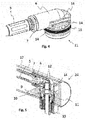
Fig. 1 bis 4 . -
Fig.1 zeigt eine Armatur 16 mit einem Auslauf 17, der eine L-Form mit einer Biegung 8 aufweist. Eine Außenoberfläche 21 des Auslaufs 17 weist keine Sichtnähte auf. Der Auslauf 17 weist zwischen einer Einlassseite 23 und einer Auslassseite 24 einen Hauptströmungsweg 18 und einen Zusatzströmungsweg 3 auf. Der Zusatzströmungsweg 3 ist in einem innerhalb des Auslaufs 17 angeordneten Schlauch 5 realisiert. Der Hauptströmungsweg 18 ist in einem Zwischenraum 19 zwischen dem Schlauch 5 und dem Auslauf 17 gebildet. Über einen Einlaufnippel 1 kann ein erstes Fluid in den Hauptströmungsweg 18 einströmen. Der Schlauch 5 ist an einem Anschluss 4 an ein Anschlussrohr 2 angeschlossen. Durch das Anschlussrohr 2 kann ein zweites Fluid in den Schlauch 5 einströmen. Weiterhin eingezeichnet ist eine schiefe Ebene 9 an der Auslassseite 24 des Auslaufs 17. An der Auslassseite 24 können sowohl das erste Fluid, als auch das zweite Fluid aus dem Auslauf 17 ausströmen. Zum Umlenken der Strömung des zweiten Fluids ist an der Auslassseite 24 ein Winkelstück 6 vorgesehen. -
Fig. 2 ist eine Vergrößerung derFig. 1 , in der die Einlassseite 23 des Auslaufs 17 gezeigt ist. Besonders gut zu erkennen sind hier der Einlassnippel 1, das Anschlussrohr 2, der Anschluss 4 und der an diesen angebundene Schlauch 5, die den Zusatzströmungsweg 3 bilden. -
Fig. 3 ist eine Vergrößerung derFig. 1 , in der die Auslassseite 24 des Auslaufs 17 gezeigt ist. Hier ist wie inFig. 1 der Schlauch 5 mit dem daran angebunden Winkelstück 6 eingezeichnet. Die Verbindung zwischen dem Schlauch 5 und dem Winkelstück 6 ist über eine Klemme 7 realisiert und drehbar (um eine Achse des Schlauchs 5) ausgeführt. Durch diese drehbare Verbindung und durch die hier ebenfalls eingezeichnete schiefe Ebene 9 kann das Winkelstück 6 bei dessen Montage nur durch Einführen des Schlauchs 5 mit daran bereits montiertem Winkelstück 6 und ohne weiteres Zutun eines Monteurs in die Montageposition des Winkelstücks 6 gebracht werden. Dies kann insbesondere durch eine abgeschrägte Kante 20 des Winkelstücks 6 erleichtert werden. Weiterhin ist zu erkennen, wie das Winkelstück 6 durch Verschrauben mit einer Lochscheibe 11 in einer Auslassöffnung 10 gehalten wird. Dazu dient ein Gewinde 22. Über Dichtungen 12, 13 kann sichergestellt werden, dass der Hauptströmungsweg 18 und der Zusatzströmungsweg 3 voneinander getrennt sind. Die erste Dichtung 12 dichtet dabei zwischen dem Winkelstück 6 und der Lochscheibe 11 ab, während die zweite Dichtung 13 zwischen der Lochscheibe 11 und dem Auslauf 17 abdichtet. Mit der Lochscheibe 11 ist weiterhin ein Mousseur 15 verschraubt. - In
Fig. 4 ist das Winkelstück 6 aus den vorherigen Figuren wiedergegeben. Daran angebunden ist über die Klemme 7 der Schlauch 5. Zu erkennen ist in dieser Darstellung, wie durch Öffnungen 14 das erste Fluid durch die Lochscheibe 11 hindurch strömen kann, so dass das erste Fluid aus der (hier nicht gezeigten) Auslassöffnung 10 austreten kann. Die zweite Dichtung 13 kann dabei eine Trennung zwischen dem Hauptströmungsweg 18 und dem Zusatzströmungsweg 3 sicherstellen (ebenfalls hier nicht eingezeichnet). -
Fig. 5 ist eine weitere Darstellung der Auslassseite 24 des Auslaufs 17 aus den vorherigen Figuren. Es wird daher auf die Beschreibungen dieser Figuren verwiesen. -
- 1 Einlaufnippel
- 2 Anschlussrohr
- 3 Zusatzströmungsweg
- 4 Anschluss
- 5 Schlauch
- 6 Winkelstück
- 7 Klemme
- 8 Biegung
- 9 schiefe Ebene
- 10 Auslassöffnung
- 11 Lochscheibe
- 12 Erste Dichtung
- 13 Zweite Dichtung
- 14 Öffnungen
- 15 Mousseur
- 16 Armatur
- 17 Auslauf
- 18 Hauptströmungsweg
- 19 Zwischenraum
- 20 abgeschrägte Kante
- 21 Außenoberfläche
- 22 Gewinde
- 23 Einlassseite
- 24 Auslassseite
Claims (10)
- Armatur (16) zur Bereitstellung mindestens eines ersten Fluids und eines zweiten Fluids aufweisend zumindest einen Auslauf (17) mit mindestens einem Hauptströmungsweg (18) für ein erstes Fluid und mindestens einem davon getrennten Zusatzströmungsweg (3) für ein zweites Fluid, wobei der Zusatzströmungsweg (3) zumindest teilweise in einem innerhalb des Auslaufs (17) angeordneten Schlauch (5) gebildet ist, wobei der Hauptströmungsweg (18) zumindest teilweise in einem Zwischenraum (19) zwischen dem Schlauch (5) und dem Auslauf (17) gebildet ist, wobei der Auslauf eine L-Form aufweist, und wobei das zweite Fluid aus einer Auslauföffnung (10) aus dem Auslauf (17) im rechten Winkel zu dem Auslauf (17) ausströmen kann.
- Armatur (16) nach Anspruch 1, wobei der Schlauch (5) an der Auslauföffnung (10) an ein Winkelstück (6) angebunden ist.
- Armatur (16) nach Anspruch 2, wobei das Winkelstück (6) mit einer Lochscheibe (11) in dem Auslauf (17) gehalten wird, wobei die Lochscheibe (11) in die Auslassöffnung (10) des Auslaufs (17) eingesetzt ist.
- Armatur (16) nach einem der Ansprüche 2 oder 3, wobei der Schlauch (5) mit dem Winkelstück (6) drehbar verbunden ist.
- Armatur (16) nach einem der Ansprüche 2 bis 4, wobei der Auslauf (17) an der Auslauföffnung (10) eine schiefe Ebene (9) aufweist, die dazu eingerichtet ist, das Winkelstück (6) bei dessen Montage in eine vorgesehene Montageposition zu bringen.
- Armatur (16) nach Anspruch 5, wobei das Winkelstück (6) eine abgeschrägte Kante (20) aufweist, die mit der schiefen Ebene (9) des Auslaufs (17) korrespondiert, wenn sich das Winkelstück (6) in dessen Montageposition befindet.
- Armatur (16) nach einem der vorherigen Ansprüche, wobei eine Außenoberfläche (21) des Auslaufs (17) frei von Sichtnähten ist.
- Verfahren zur Herstellung einer Armatur (16) gemäß einem der vorherigen Ansprüche umfassend zumindest die folgenden Verfahrensschritte:a) Bereitstellen des zumindest eines Auslaufs (17),b) Einführen des Schlauchs (5) in den Auslauf (17), undc) Befestigen des Schlauchs (5) in dem Auslauf (17).
- Verfahren nach Anspruch 8, wobei an dem Schlauch (5) ein Winkelstück (6) vorgesehen ist, das in Schritt c) durch Einsetzen einer Lochscheibe (11) in eine Auslauföffnung (10) des Auslaufs (17) befestigt wird.
- Verfahren nach Anspruch 9, wobei bei dem Einführen des Schlauchs (5) in den Auslauf (17) gemäß Schritt b) eine schiefe Ebene (9) innerhalb des Auslaufs (17) dazu genutzt wird, das Winkelstück (6) in eine vorgesehene Montageposition zu bringen.
Applications Claiming Priority (1)
| Application Number | Priority Date | Filing Date | Title |
|---|---|---|---|
| DE102016010527.5A DE102016010527A1 (de) | 2016-09-01 | 2016-09-01 | Armatur zur Bereitstellung eines Fluids und eines zweiten Fluids |
Publications (2)
| Publication Number | Publication Date |
|---|---|
| EP3290600A1 true EP3290600A1 (de) | 2018-03-07 |
| EP3290600B1 EP3290600B1 (de) | 2019-12-18 |
Family
ID=59581755
Family Applications (1)
| Application Number | Title | Priority Date | Filing Date |
|---|---|---|---|
| EP17185522.4A Active EP3290600B1 (de) | 2016-09-01 | 2017-08-09 | Armatur zur bereitstellung eines ersten fluids und eines zweiten fluids und verfahren zur herstellung deren |
Country Status (3)
| Country | Link |
|---|---|
| EP (1) | EP3290600B1 (de) |
| DE (1) | DE102016010527A1 (de) |
| ES (1) | ES2773176T3 (de) |
Cited By (1)
| Publication number | Priority date | Publication date | Assignee | Title |
|---|---|---|---|---|
| DE102022130727A1 (de) * | 2022-11-21 | 2024-05-23 | Franz Joseph Schütte GmbH | Sanitärarmatur |
Families Citing this family (1)
| Publication number | Priority date | Publication date | Assignee | Title |
|---|---|---|---|---|
| DE202019101013U1 (de) | 2019-02-21 | 2020-05-25 | Wwb Sweden Ab | Auslaufarmatur |
Citations (3)
| Publication number | Priority date | Publication date | Assignee | Title |
|---|---|---|---|---|
| GB2211089A (en) * | 1987-10-22 | 1989-06-28 | Raf Rubinetterie | Mixer tap with liquid soap dispenser |
| DE69110630T2 (de) * | 1990-12-05 | 1995-12-14 | Telma Guzzini S.R.L., Montelupone, Macerata | Ausgabevorrichtungen mit Mehrwegehahn. |
| US20050189023A1 (en) * | 2004-02-27 | 2005-09-01 | Yu-You Hsien | Dual use stand type faucet used in kitchen |
Family Cites Families (9)
| Publication number | Priority date | Publication date | Assignee | Title |
|---|---|---|---|---|
| CH657403A5 (de) | 1981-08-21 | 1986-08-29 | Karrer Weber & Cie Ag | Auslaufvorrichtung an einer sanitaerarmatur fuer kalt- und warmwasser. |
| DE20209799U1 (de) | 2002-06-24 | 2003-11-13 | Bolderheij Fok Cornelis | Multifunktionsarmatur |
| ITMI20051252A1 (it) | 2005-07-01 | 2007-01-02 | Fabrizio Nobili | Gruppo per l'erogazione differenziabile di acqua trattata e di acqua di rete |
| US20070235091A1 (en) | 2006-04-06 | 2007-10-11 | Yoav Granot | Water tap assembly having a pull-out water-discharge head |
| GB0707326D0 (en) | 2007-04-16 | 2007-05-23 | Avilion Ltd | Diverter valve |
| DE102008006255B4 (de) | 2008-01-25 | 2013-09-19 | Grohe Ag | Vorrichtung zur Abgabe von Wasser |
| DE202012104023U1 (de) | 2012-10-19 | 2014-02-10 | Miscea Gmbh | Multifunktionsarmatur |
| DE202013002188U1 (de) | 2013-03-08 | 2014-06-11 | Neoperl Gmbh | Sanitäres Einbauteil, Innenschlauchanordnung für eine Sanitärarmatur und Sanitärarmatur |
| DE102014109822B4 (de) | 2014-07-14 | 2025-06-12 | Blanco Gmbh + Co Kg | Armatur |
-
2016
- 2016-09-01 DE DE102016010527.5A patent/DE102016010527A1/de not_active Withdrawn
-
2017
- 2017-08-09 ES ES17185522T patent/ES2773176T3/es active Active
- 2017-08-09 EP EP17185522.4A patent/EP3290600B1/de active Active
Patent Citations (3)
| Publication number | Priority date | Publication date | Assignee | Title |
|---|---|---|---|---|
| GB2211089A (en) * | 1987-10-22 | 1989-06-28 | Raf Rubinetterie | Mixer tap with liquid soap dispenser |
| DE69110630T2 (de) * | 1990-12-05 | 1995-12-14 | Telma Guzzini S.R.L., Montelupone, Macerata | Ausgabevorrichtungen mit Mehrwegehahn. |
| US20050189023A1 (en) * | 2004-02-27 | 2005-09-01 | Yu-You Hsien | Dual use stand type faucet used in kitchen |
Cited By (1)
| Publication number | Priority date | Publication date | Assignee | Title |
|---|---|---|---|---|
| DE102022130727A1 (de) * | 2022-11-21 | 2024-05-23 | Franz Joseph Schütte GmbH | Sanitärarmatur |
Also Published As
| Publication number | Publication date |
|---|---|
| EP3290600B1 (de) | 2019-12-18 |
| ES2773176T3 (es) | 2020-07-09 |
| DE102016010527A1 (de) | 2018-03-01 |
Similar Documents
| Publication | Publication Date | Title |
|---|---|---|
| DE102017101566B3 (de) | Schlauchanschlussanordnung, Verwendung einer Schlauchanschlussanordnung und Sanitärarmatur | |
| DE202017100423U1 (de) | Schlauchanschlussanordnung, Verwendung einer Schlauchanschlussanordnung und Sanitärarmatur | |
| DE202020104394U1 (de) | Sanitärschnittstelle, Sanitärarmatur, Baukasten zur Herstellung einer Sanitärschnittstelle und Verwendung einer Sanitärschnittstelle | |
| EP3290600B1 (de) | Armatur zur bereitstellung eines ersten fluids und eines zweiten fluids und verfahren zur herstellung deren | |
| EP3690155B1 (de) | Armaturenanordnung | |
| DE102007000644B4 (de) | Heizkernanschlussrohr und Fluidtransportsystem | |
| AT396605B (de) | Unterputzanschlussstück für sanitärarmaturen | |
| WO2014154716A1 (de) | Rohranschlussadapter und sanitärarmatur | |
| DE102015201631A1 (de) | Motorölfiltervorrichtung, Motorschmiersystem und Fahrzeug | |
| DE102014203600A1 (de) | Schweißbrenner | |
| DE60006546T2 (de) | Anschluss für einen wasserzähler | |
| DE102010031896B4 (de) | Hahnverlängerungsfitting zum Anschluss an einen Wandanschlussfitting und Wandanschlussfitting | |
| WO2020169763A1 (de) | Modulares ventilkörpersystem | |
| DE102019119302A1 (de) | Ablaufstutzen zum getrennten Auslassen von Flüssigkeiten unterschiedlicher Dichte | |
| AT411553B (de) | Anschlussarmatur für einen plattenheizkörper | |
| DE3233591C1 (de) | Absperrbare Armatur für Wasserzähler mit Einrohranschluß | |
| DE112015001885T5 (de) | Ventil zum Reinigen eines Versorgungsrohrs | |
| DE102006043801B4 (de) | Bauteil zum Kreuzen von mit einem Medium durchströmbaren Rohrleitungen | |
| DE187168C (de) | ||
| EP2060855A1 (de) | Anschlussstück für ein schlauchförmiges Innenzirkulationsrohr, Wasserzirkulationsleitung mit einem solchen Abschlussstück und Verfahren zum Montieren einer solchen Wasserzirkulationsleitung | |
| EP3425247A1 (de) | Ventil zur mischung zweier gasströme | |
| EP2146773B1 (de) | Verfahren zur Herstellung einer Rohr- und Schlauchverbindung | |
| DE937669C (de) | Anschlussarmatur fuer Mengenzaehler, insbesondere Gaszaehler | |
| DE329688C (de) | Hahn mit Hilfsverschluss | |
| DE202015101764U1 (de) | Expansionsventil |
Legal Events
| Date | Code | Title | Description |
|---|---|---|---|
| PUAI | Public reference made under article 153(3) epc to a published international application that has entered the european phase |
Free format text: ORIGINAL CODE: 0009012 |
|
| STAA | Information on the status of an ep patent application or granted ep patent |
Free format text: STATUS: THE APPLICATION HAS BEEN PUBLISHED |
|
| AK | Designated contracting states |
Kind code of ref document: A1 Designated state(s): AL AT BE BG CH CY CZ DE DK EE ES FI FR GB GR HR HU IE IS IT LI LT LU LV MC MK MT NL NO PL PT RO RS SE SI SK SM TR |
|
| AX | Request for extension of the european patent |
Extension state: BA ME |
|
| STAA | Information on the status of an ep patent application or granted ep patent |
Free format text: STATUS: REQUEST FOR EXAMINATION WAS MADE |
|
| 17P | Request for examination filed |
Effective date: 20180906 |
|
| RBV | Designated contracting states (corrected) |
Designated state(s): AL AT BE BG CH CY CZ DE DK EE ES FI FR GB GR HR HU IE IS IT LI LT LU LV MC MK MT NL NO PL PT RO RS SE SI SK SM TR |
|
| GRAP | Despatch of communication of intention to grant a patent |
Free format text: ORIGINAL CODE: EPIDOSNIGR1 |
|
| STAA | Information on the status of an ep patent application or granted ep patent |
Free format text: STATUS: GRANT OF PATENT IS INTENDED |
|
| INTG | Intention to grant announced |
Effective date: 20191011 |
|
| GRAS | Grant fee paid |
Free format text: ORIGINAL CODE: EPIDOSNIGR3 |
|
| GRAA | (expected) grant |
Free format text: ORIGINAL CODE: 0009210 |
|
| STAA | Information on the status of an ep patent application or granted ep patent |
Free format text: STATUS: THE PATENT HAS BEEN GRANTED |
|
| AK | Designated contracting states |
Kind code of ref document: B1 Designated state(s): AL AT BE BG CH CY CZ DE DK EE ES FI FR GB GR HR HU IE IS IT LI LT LU LV MC MK MT NL NO PL PT RO RS SE SI SK SM TR |
|
| REG | Reference to a national code |
Ref country code: CH Ref legal event code: EP |
|
| REG | Reference to a national code |
Ref country code: DE Ref legal event code: R096 Ref document number: 502017003164 Country of ref document: DE |
|
| REG | Reference to a national code |
Ref country code: IE Ref legal event code: FG4D Free format text: LANGUAGE OF EP DOCUMENT: GERMAN |
|
| REG | Reference to a national code |
Ref country code: AT Ref legal event code: REF Ref document number: 1214733 Country of ref document: AT Kind code of ref document: T Effective date: 20200115 |
|
| REG | Reference to a national code |
Ref country code: NL Ref legal event code: FP |
|
| PG25 | Lapsed in a contracting state [announced via postgrant information from national office to epo] |
Ref country code: NO Free format text: LAPSE BECAUSE OF FAILURE TO SUBMIT A TRANSLATION OF THE DESCRIPTION OR TO PAY THE FEE WITHIN THE PRESCRIBED TIME-LIMIT Effective date: 20200318 Ref country code: GR Free format text: LAPSE BECAUSE OF FAILURE TO SUBMIT A TRANSLATION OF THE DESCRIPTION OR TO PAY THE FEE WITHIN THE PRESCRIBED TIME-LIMIT Effective date: 20200319 Ref country code: SE Free format text: LAPSE BECAUSE OF FAILURE TO SUBMIT A TRANSLATION OF THE DESCRIPTION OR TO PAY THE FEE WITHIN THE PRESCRIBED TIME-LIMIT Effective date: 20191218 Ref country code: LV Free format text: LAPSE BECAUSE OF FAILURE TO SUBMIT A TRANSLATION OF THE DESCRIPTION OR TO PAY THE FEE WITHIN THE PRESCRIBED TIME-LIMIT Effective date: 20191218 Ref country code: LT Free format text: LAPSE BECAUSE OF FAILURE TO SUBMIT A TRANSLATION OF THE DESCRIPTION OR TO PAY THE FEE WITHIN THE PRESCRIBED TIME-LIMIT Effective date: 20191218 Ref country code: FI Free format text: LAPSE BECAUSE OF FAILURE TO SUBMIT A TRANSLATION OF THE DESCRIPTION OR TO PAY THE FEE WITHIN THE PRESCRIBED TIME-LIMIT Effective date: 20191218 Ref country code: BG Free format text: LAPSE BECAUSE OF FAILURE TO SUBMIT A TRANSLATION OF THE DESCRIPTION OR TO PAY THE FEE WITHIN THE PRESCRIBED TIME-LIMIT Effective date: 20200318 |
|
| REG | Reference to a national code |
Ref country code: LT Ref legal event code: MG4D |
|
| PG25 | Lapsed in a contracting state [announced via postgrant information from national office to epo] |
Ref country code: RS Free format text: LAPSE BECAUSE OF FAILURE TO SUBMIT A TRANSLATION OF THE DESCRIPTION OR TO PAY THE FEE WITHIN THE PRESCRIBED TIME-LIMIT Effective date: 20191218 Ref country code: HR Free format text: LAPSE BECAUSE OF FAILURE TO SUBMIT A TRANSLATION OF THE DESCRIPTION OR TO PAY THE FEE WITHIN THE PRESCRIBED TIME-LIMIT Effective date: 20191218 |
|
| PG25 | Lapsed in a contracting state [announced via postgrant information from national office to epo] |
Ref country code: AL Free format text: LAPSE BECAUSE OF FAILURE TO SUBMIT A TRANSLATION OF THE DESCRIPTION OR TO PAY THE FEE WITHIN THE PRESCRIBED TIME-LIMIT Effective date: 20191218 |
|
| REG | Reference to a national code |
Ref country code: ES Ref legal event code: FG2A Ref document number: 2773176 Country of ref document: ES Kind code of ref document: T3 Effective date: 20200709 |
|
| PG25 | Lapsed in a contracting state [announced via postgrant information from national office to epo] |
Ref country code: EE Free format text: LAPSE BECAUSE OF FAILURE TO SUBMIT A TRANSLATION OF THE DESCRIPTION OR TO PAY THE FEE WITHIN THE PRESCRIBED TIME-LIMIT Effective date: 20191218 Ref country code: PT Free format text: LAPSE BECAUSE OF FAILURE TO SUBMIT A TRANSLATION OF THE DESCRIPTION OR TO PAY THE FEE WITHIN THE PRESCRIBED TIME-LIMIT Effective date: 20200513 Ref country code: CZ Free format text: LAPSE BECAUSE OF FAILURE TO SUBMIT A TRANSLATION OF THE DESCRIPTION OR TO PAY THE FEE WITHIN THE PRESCRIBED TIME-LIMIT Effective date: 20191218 Ref country code: RO Free format text: LAPSE BECAUSE OF FAILURE TO SUBMIT A TRANSLATION OF THE DESCRIPTION OR TO PAY THE FEE WITHIN THE PRESCRIBED TIME-LIMIT Effective date: 20191218 |
|
| PG25 | Lapsed in a contracting state [announced via postgrant information from national office to epo] |
Ref country code: SM Free format text: LAPSE BECAUSE OF FAILURE TO SUBMIT A TRANSLATION OF THE DESCRIPTION OR TO PAY THE FEE WITHIN THE PRESCRIBED TIME-LIMIT Effective date: 20191218 Ref country code: IS Free format text: LAPSE BECAUSE OF FAILURE TO SUBMIT A TRANSLATION OF THE DESCRIPTION OR TO PAY THE FEE WITHIN THE PRESCRIBED TIME-LIMIT Effective date: 20200418 Ref country code: SK Free format text: LAPSE BECAUSE OF FAILURE TO SUBMIT A TRANSLATION OF THE DESCRIPTION OR TO PAY THE FEE WITHIN THE PRESCRIBED TIME-LIMIT Effective date: 20191218 |
|
| REG | Reference to a national code |
Ref country code: DE Ref legal event code: R097 Ref document number: 502017003164 Country of ref document: DE |
|
| PLBE | No opposition filed within time limit |
Free format text: ORIGINAL CODE: 0009261 |
|
| STAA | Information on the status of an ep patent application or granted ep patent |
Free format text: STATUS: NO OPPOSITION FILED WITHIN TIME LIMIT |
|
| PG25 | Lapsed in a contracting state [announced via postgrant information from national office to epo] |
Ref country code: DK Free format text: LAPSE BECAUSE OF FAILURE TO SUBMIT A TRANSLATION OF THE DESCRIPTION OR TO PAY THE FEE WITHIN THE PRESCRIBED TIME-LIMIT Effective date: 20191218 |
|
| 26N | No opposition filed |
Effective date: 20200921 |
|
| PG25 | Lapsed in a contracting state [announced via postgrant information from national office to epo] |
Ref country code: SI Free format text: LAPSE BECAUSE OF FAILURE TO SUBMIT A TRANSLATION OF THE DESCRIPTION OR TO PAY THE FEE WITHIN THE PRESCRIBED TIME-LIMIT Effective date: 20191218 |
|
| PG25 | Lapsed in a contracting state [announced via postgrant information from national office to epo] |
Ref country code: PL Free format text: LAPSE BECAUSE OF FAILURE TO SUBMIT A TRANSLATION OF THE DESCRIPTION OR TO PAY THE FEE WITHIN THE PRESCRIBED TIME-LIMIT Effective date: 20191218 |
|
| PG25 | Lapsed in a contracting state [announced via postgrant information from national office to epo] |
Ref country code: MC Free format text: LAPSE BECAUSE OF FAILURE TO SUBMIT A TRANSLATION OF THE DESCRIPTION OR TO PAY THE FEE WITHIN THE PRESCRIBED TIME-LIMIT Effective date: 20191218 |
|
| PG25 | Lapsed in a contracting state [announced via postgrant information from national office to epo] |
Ref country code: LU Free format text: LAPSE BECAUSE OF NON-PAYMENT OF DUE FEES Effective date: 20200809 |
|
| REG | Reference to a national code |
Ref country code: BE Ref legal event code: MM Effective date: 20200831 |
|
| PG25 | Lapsed in a contracting state [announced via postgrant information from national office to epo] |
Ref country code: IE Free format text: LAPSE BECAUSE OF NON-PAYMENT OF DUE FEES Effective date: 20200809 Ref country code: BE Free format text: LAPSE BECAUSE OF NON-PAYMENT OF DUE FEES Effective date: 20200831 |
|
| PG25 | Lapsed in a contracting state [announced via postgrant information from national office to epo] |
Ref country code: TR Free format text: LAPSE BECAUSE OF FAILURE TO SUBMIT A TRANSLATION OF THE DESCRIPTION OR TO PAY THE FEE WITHIN THE PRESCRIBED TIME-LIMIT Effective date: 20191218 Ref country code: MT Free format text: LAPSE BECAUSE OF FAILURE TO SUBMIT A TRANSLATION OF THE DESCRIPTION OR TO PAY THE FEE WITHIN THE PRESCRIBED TIME-LIMIT Effective date: 20191218 Ref country code: CY Free format text: LAPSE BECAUSE OF FAILURE TO SUBMIT A TRANSLATION OF THE DESCRIPTION OR TO PAY THE FEE WITHIN THE PRESCRIBED TIME-LIMIT Effective date: 20191218 |
|
| PG25 | Lapsed in a contracting state [announced via postgrant information from national office to epo] |
Ref country code: MK Free format text: LAPSE BECAUSE OF FAILURE TO SUBMIT A TRANSLATION OF THE DESCRIPTION OR TO PAY THE FEE WITHIN THE PRESCRIBED TIME-LIMIT Effective date: 20191218 |
|
| P01 | Opt-out of the competence of the unified patent court (upc) registered |
Effective date: 20230526 |
|
| REG | Reference to a national code |
Ref country code: AT Ref legal event code: MM01 Ref document number: 1214733 Country of ref document: AT Kind code of ref document: T Effective date: 20220809 |
|
| PG25 | Lapsed in a contracting state [announced via postgrant information from national office to epo] |
Ref country code: AT Free format text: LAPSE BECAUSE OF NON-PAYMENT OF DUE FEES Effective date: 20220809 |
|
| PGFP | Annual fee paid to national office [announced via postgrant information from national office to epo] |
Ref country code: GB Payment date: 20230822 Year of fee payment: 7 Ref country code: CH Payment date: 20230902 Year of fee payment: 7 |
|
| PGFP | Annual fee paid to national office [announced via postgrant information from national office to epo] |
Ref country code: ES Payment date: 20231027 Year of fee payment: 7 |
|
| REG | Reference to a national code |
Ref country code: CH Ref legal event code: PL |
|
| GBPC | Gb: european patent ceased through non-payment of renewal fee |
Effective date: 20240809 |
|
| PG25 | Lapsed in a contracting state [announced via postgrant information from national office to epo] |
Ref country code: CH Free format text: LAPSE BECAUSE OF NON-PAYMENT OF DUE FEES Effective date: 20240831 |
|
| PG25 | Lapsed in a contracting state [announced via postgrant information from national office to epo] |
Ref country code: GB Free format text: LAPSE BECAUSE OF NON-PAYMENT OF DUE FEES Effective date: 20240809 |
|
| PGFP | Annual fee paid to national office [announced via postgrant information from national office to epo] |
Ref country code: NL Payment date: 20250804 Year of fee payment: 9 |
|
| REG | Reference to a national code |
Ref country code: ES Ref legal event code: FD2A Effective date: 20250926 |
|
| PG25 | Lapsed in a contracting state [announced via postgrant information from national office to epo] |
Ref country code: ES Free format text: LAPSE BECAUSE OF NON-PAYMENT OF DUE FEES Effective date: 20240810 |
|
| PGFP | Annual fee paid to national office [announced via postgrant information from national office to epo] |
Ref country code: DE Payment date: 20250806 Year of fee payment: 9 |
|
| PGFP | Annual fee paid to national office [announced via postgrant information from national office to epo] |
Ref country code: IT Payment date: 20250818 Year of fee payment: 9 |
|
| PGFP | Annual fee paid to national office [announced via postgrant information from national office to epo] |
Ref country code: FR Payment date: 20250801 Year of fee payment: 9 |