EP3290568B1 - Lave-linge avec un distributeur de detergent - Google Patents
Lave-linge avec un distributeur de detergent Download PDFInfo
- Publication number
- EP3290568B1 EP3290568B1 EP16187291.6A EP16187291A EP3290568B1 EP 3290568 B1 EP3290568 B1 EP 3290568B1 EP 16187291 A EP16187291 A EP 16187291A EP 3290568 B1 EP3290568 B1 EP 3290568B1
- Authority
- EP
- European Patent Office
- Prior art keywords
- cover element
- aperture
- drawer
- compartment
- machine
- Prior art date
- Legal status (The legal status is an assumption and is not a legal conclusion. Google has not performed a legal analysis and makes no representation as to the accuracy of the status listed.)
- Revoked
Links
- 238000010412 laundry washing Methods 0.000 title claims description 41
- 239000003599 detergent Substances 0.000 title description 39
- 239000003795 chemical substances by application Substances 0.000 claims description 103
- XLYOFNOQVPJJNP-UHFFFAOYSA-N water Substances O XLYOFNOQVPJJNP-UHFFFAOYSA-N 0.000 claims description 69
- 238000005406 washing Methods 0.000 claims description 43
- 230000004888 barrier function Effects 0.000 claims description 6
- 230000001681 protective effect Effects 0.000 claims description 6
- 239000007788 liquid Substances 0.000 description 40
- 239000000843 powder Substances 0.000 description 14
- 239000000654 additive Substances 0.000 description 5
- 230000000694 effects Effects 0.000 description 5
- 238000011068 loading method Methods 0.000 description 5
- 238000001035 drying Methods 0.000 description 4
- 238000009825 accumulation Methods 0.000 description 3
- 239000007844 bleaching agent Substances 0.000 description 3
- 239000004744 fabric Substances 0.000 description 3
- 239000002979 fabric softener Substances 0.000 description 3
- 238000000034 method Methods 0.000 description 3
- 241000894006 Bacteria Species 0.000 description 2
- ZAMOUSCENKQFHK-UHFFFAOYSA-N Chlorine atom Chemical compound [Cl] ZAMOUSCENKQFHK-UHFFFAOYSA-N 0.000 description 2
- 230000009471 action Effects 0.000 description 2
- 239000000460 chlorine Substances 0.000 description 2
- 229910052801 chlorine Inorganic materials 0.000 description 2
- 239000003623 enhancer Substances 0.000 description 2
- 238000011049 filling Methods 0.000 description 2
- 230000035755 proliferation Effects 0.000 description 2
- 238000011012 sanitization Methods 0.000 description 2
- 238000004078 waterproofing Methods 0.000 description 2
- 239000006096 absorbing agent Substances 0.000 description 1
- 238000011010 flushing procedure Methods 0.000 description 1
- 239000003292 glue Substances 0.000 description 1
- 238000001746 injection moulding Methods 0.000 description 1
- 238000004519 manufacturing process Methods 0.000 description 1
- 239000000463 material Substances 0.000 description 1
- 238000002156 mixing Methods 0.000 description 1
- 230000004048 modification Effects 0.000 description 1
- 238000012986 modification Methods 0.000 description 1
- 239000004033 plastic Substances 0.000 description 1
- 238000009428 plumbing Methods 0.000 description 1
- 230000009467 reduction Effects 0.000 description 1
- 230000035943 smell Effects 0.000 description 1
- 238000009987 spinning Methods 0.000 description 1
- 210000002105 tongue Anatomy 0.000 description 1
- 238000003466 welding Methods 0.000 description 1
Images


Classifications
-
- D—TEXTILES; PAPER
- D06—TREATMENT OF TEXTILES OR THE LIKE; LAUNDERING; FLEXIBLE MATERIALS NOT OTHERWISE PROVIDED FOR
- D06F—LAUNDERING, DRYING, IRONING, PRESSING OR FOLDING TEXTILE ARTICLES
- D06F39/00—Details of washing machines not specific to a single type of machines covered by groups D06F9/00 - D06F27/00
- D06F39/02—Devices for adding soap or other washing agents
-
- D—TEXTILES; PAPER
- D06—TREATMENT OF TEXTILES OR THE LIKE; LAUNDERING; FLEXIBLE MATERIALS NOT OTHERWISE PROVIDED FOR
- D06F—LAUNDERING, DRYING, IRONING, PRESSING OR FOLDING TEXTILE ARTICLES
- D06F21/00—Washing machines with receptacles, e.g. perforated, having a rotary movement, e.g. oscillatory movement
- D06F21/02—Washing machines with receptacles, e.g. perforated, having a rotary movement, e.g. oscillatory movement about a horizontal axis
- D06F21/04—Washing machines with receptacles, e.g. perforated, having a rotary movement, e.g. oscillatory movement about a horizontal axis within an enclosing receptacle
-
- D—TEXTILES; PAPER
- D06—TREATMENT OF TEXTILES OR THE LIKE; LAUNDERING; FLEXIBLE MATERIALS NOT OTHERWISE PROVIDED FOR
- D06F—LAUNDERING, DRYING, IRONING, PRESSING OR FOLDING TEXTILE ARTICLES
- D06F39/00—Details of washing machines not specific to a single type of machines covered by groups D06F9/00 - D06F27/00
- D06F39/02—Devices for adding soap or other washing agents
- D06F39/028—Arrangements for selectively supplying water to detergent compartments
Definitions
- the present invention concerns the field of laundry washing techniques.
- the present invention refers to a treating agents dispenser in a laundry washing machine.
- laundry washing machines both "simple” laundry washing machines (i.e. laundry washing machines which can only wash and rinse laundry) and laundry washing-drying machines (i.e. laundry washing machines which can also dry laundry), is widespread.
- laundry washing machine will refer to both simple laundry washing machine and laundry washing-drying machine.
- Laundry washing machines generally comprise an external casing, or cabinet, provided with a washing tub which contains a rotatable perforated drum where the laundry is placed.
- a loading/unloading door ensures access to the drum.
- Laundry washing machines typically comprise a treating agents dispenser for the introduction of water and treating agents (i.e. detergent, softener, rinse conditioner, etc.) into the tub.
- treating agents i.e. detergent, softener, rinse conditioner, etc.
- Known treating agents dispensers comprise a drawer having one or more open topped compartments adapted to be filled with at least one treating agent and one or more respective channels for conveying water to the compartments.
- Treating agents dispenser also comprises a housing on which the drawer can slide from a normal closed position to an opening position.
- the housing is typically mounted at an opening provided on the upper part of the front side of the cabinet.
- the opening allows entrance and exit of the drawer so that it can be positioned by the user in said positions.
- the housing of the known type preferably has a box-like structure comprising upright side walls which are connected below by a bottom side wall.
- the treating agents dispenser then comprises a water distributor which preferably connects above the upright side walls of the housing.
- the water distributor is advantageously placed above the compartments and opportunely shaped to define said channels which are provided with apertures allowing water coming from an external water source to fall down in the underlying compartments.
- the bottom side wall of the housing communicates with a supply pipe connected to the tub for guiding and supplying the water, which passes through the compartments and which mixes with the treating agent, into the tub.
- Compartments are opportunely shaped to allow the treating agent and water flowing therethrough to reach the bottom side of the housing and then, from there, to the tub through the supply pipe.
- compartments comprise an outlet aperture through which water and treating agent flow. The mixed liquid then flows towards the bottom side of the housing.
- compartments comprise a siphon. Water coming from the channel flushed into the compartment triggers the siphon and treating agent is drawn through the siphon. Treating agent and water then fall down into the housing.
- compartments are shaped so that water and treating agent overflow from the compartment and fall down into the housing.
- Document EP 2703545A2 discloses a washing machine equipped with a detergent supply device including a housing, a detergent case to store a detergent, the detergent case being movably coupled to the housing, a water supply frame coupled to an upper portion of the housing to guide water to the detergent case, and a cover frame to sealingly cover an upper portion of the water supply frame.
- a first drawback posed by the treating agents dispensers of the known art lies in that the treating agent which is inserted into the respective compartment, in particular when a powder treating agent is used, is not totally flushed by water falling down from the apertures of the water distributor channels and residues of the treating agent are left in the compartment. Residues of treating agent may accumulate and may form a sticky, gelatinous mass, which will ultimately adhere to the side walls of the compartment.
- treating agents dispensers of the known art Another drawback posed by the treating agents dispensers of the known art is that the accumulation of treating agent may favour the proliferation of bacteria, which may then worsen the hygienic conditions and may cause bad smells.
- washing performance may be different for each washing program depending on the percentage of product left on the compartment. Therefore, the washing performance may vary from time to time and cannot be properly controlled.
- the object of the present invention is therefore to overcome the drawbacks posed by the known technique.
- a laundry washing machine having a treating agents dispenser comprising a drawer having one or more open-top compartments for receiving at least one agent for treating laundry wherein a cover element is associated to the upper side of the drawer, preferably movably connected to the upper side of the drawer, it is possible to reduce or prevent residues of treating agent in the treating agents dispensers compared to known techniques.
- the present invention relates, therefore, to a laundry washing machine connectable to an external water source comprising a cabinet supporting a washing tub enclosing a rotatable washing drum suited to receive laundry and a treating agents dispenser connectable to said external water source and fluidly connected to said washing tub, said treating agents dispenser comprising:
- the cover element comprises an upper side and an opposite underside, wherein the upper side of the cover element faces the water distributor and the underside side of the cover element faces the upper side of the drawer.
- a first aperture of said at least one aperture of the cover element is positioned above a first compartment of said one or more open-top compartments and a second aperture of said at least one aperture of the cover element is positioned above a second compartment of said one or more open-top compartments.
- two apertures of said at least one aperture of the cover element are positioned above a first compartment of said one or more open-top compartments.
- the size of said at least one aperture is smaller than the size of the underlying compartment.
- the boundary line of the at least one aperture is smaller than the boundary line of the underlying compartment.
- At least a portion of the boundary line of said at least one aperture follows the boundary line of the underlying compartment.
- said at least one aperture comprises a rim extending downwardly from the boundary line towards the underlying compartment.
- At least a portion of the rim is received in a recess of the underlying compartment.
- the cover element comprises at least one level indicator for said at least one treating agent.
- said rim comprises said level indicator.
- the drawer comprises a border rim which at least partially externally delimits the compartments and the cover element peripherally borders said border rim of the drawer.
- the size of said cover element is substantially equal to the size of said drawer or the length of the cover element is substantially equal to the length of the drawer or the width of the cover element is substantially equal to the width of the drawer.
- the cover element has a length so that it is partially inserted in the supporting structure when the drawer is in its maximum opened position.
- the cover element is removably connected to the upper side of the drawer.
- the treating agents dispenser comprises a release device realesably connecting the cover element to the drawer.
- the release device realesably connects the cover element to an upper side of the drawer
- a first one of said at least one aperture is realized in a first surface of an upper side of the cover element and a second one of said at least one aperture is realized in a second surface of the upper side of the cover element, wherein the first surface is at a different level with respect to the second surface.
- a first one of said at least one aperture is realized in a first surface of the upper side of the cover element and a second one of said at least one aperture is realized in a second surface of the upper side of the cover element, wherein the first surface and the second surface are separated by a protective barrier.
- At least one of said one or more compartments comprises and outlet apt to fluidly connecting said at least one of said one or more compartments to an underside of the drawer.
- said outlet comprises a siphon.
- the underside of said cover element comprises a cap siphon.
- the cap siphon is integrally made with the cover element.
- the present invention has proved to be particularly advantageous when applied to laundry washing machines, as described below. It should in any case be underlined that the present invention is not limited to laundry washing machines. On the contrary, the present invention can be conveniently applied to laundry washing-drying machines (i.e. laundry washing machines which can also dry laundry).
- laundry washing machine will refer to both simple laundry washing machine and laundry washing-drying machine.
- a laundry washing machine 1 equipped with a treating agents dispenser 20 according to a preferred embodiment of the invention is described with reference to Figures 1 to 16 .
- the laundry washing machine 1 comprises an external casing or cabinet 2 in which a washing tub, not shown, is provided that contains a perforated washing drum, not shown, where the laundry to be treated can be loaded.
- the cabinet 2 comprises a vertical front side wall 2a, a vertical rear side wall 2b, two vertical lateral side walls 2c, 2d and an upper side wall 2e.
- the cabinet 2 is provided with a loading/unloading door 8 which allows access to the drum.
- the tub is preferably suspended in a floating manner inside the cabinet 2, advantageously by means of a number of coil springs and shock-absorbers.
- the drum is advantageously rotated by an electric motor (not shown) which preferably transmits the rotating motion to the shaft of the drum, advantageously by means of a belt/pulley system (not shown).
- the motor can be directly associated with the shaft of the drum.
- the drum is advantageously provided with holes which allow the liquid flowing therethrough. Said holes are typically and preferably homogeneously distributed on the cylindrical side wall of the drum.
- Laundry washing machine 1 advantageously comprises a control unit (not shown), connected to the various parts of the laundry washing machine 1 in order to ensure its operation.
- Laundry washing machine 1 preferably comprises an interface unit 16, connected to the control unit, accessible to the user and by means of which the user may select and set the washing parameters, like for example a desired washing program. Usually, other parameters can optionally be inserted by the user, for example the washing temperature, the spinning speed, etc..
- the interface unit 16 preferably comprises a display 16a which displays machine working conditions.
- the unit interface 16 then preferably comprises one or more selector devices which allow to select the appropriate washing program and/or to set other parameters.
- the selector device may comprise a rotary knob 16b which advantageously allows to select the appropriate washing program.
- the selector devices may then preferably comprise push buttons.
- the laundry washing machine 1 advantageously comprises said treating agents dispenser 20 to supply treating agents into the tub during a washing cycle.
- Treating agents may comprise, for example, detergents, rinse additives, fabric softeners or fabric conditioners, waterproofing agents, fabric enhancers, rinse sanitization additives, chlorine-based additives, etc..
- the treating agents dispenser 20 comprises a supporting structure 21, connected to the cabinet 2, internally to the latter, preferably by suitable fixing means, comprising, for example, screws or rivets, not illustrated, or also glue, or welding.
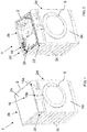
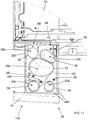
- the supporting structure 21 comprises a housing, more preferably a box-shaped housing 21, as illustrated in Figure 6 .
- the housing 21 is advantageously substantially parallelepiped and it is connected to the frontal side wall 2a of the cabinet 2, opportunely in an upper region of the latter, positioned above the tub.
- the housing 21 preferably comprises a bottom side wall 21a and lateral vertical side walls 21b, 21c, as visible in Figure 6 .
- An outlet port 21d is preferably defined at the rear portion of the bottom side wall 21a.
- the outlet port 21d is adapted to allow the flowing of a liquid into a supply pipe (not shown) fluidly connecting the treating agents dispenser 20 to the washing tub.
- the housing 21 is suited to receive a drawer 22, preferably a slidable drawer 22, which can be extracted from the housing 21, such as to protrude from the cabinet 2 in an opened position, as illustrated for example in Figures 3 and 4 , or can be fully inserted into the housing 21 in a closed operational position, as illustrated in Figures 1 and 2 .
- the drawer 22 preferably comprises a front panel 15 associated to a frontal part of the drawer 22 and preferably has a handle by means of which the drawer 22 can be moved from the closed position and an opened position and, vice-versa, can be moved from the opened position to the closed position.
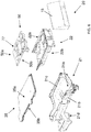
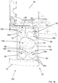
- the drawer 22 preferably comprises an upper side 22a and an opposite underside 22b, as illustrated in Figure 7B .
- the drawer 22 is preferably provided with one or more compartments 23a, 23b, 23c, 23d adapted to be filled with treating agents.
- compartments 23a, 23b, 23c, 23d are preferably opened upwardly, i.e. open-top, to allow filling with treating agents from above.
- Each compartment 23a, 23b, 23c, 23d preferably defines a respective top boundary line 63a, 63b, 63c, 63d.
- the number of compartments may be different, according to the desired type and number of treating agents which are used in the particular model of laundry washing machine.
- the first compartment 23a is preferably adapted for receiving a powder detergent and/or a unit dose package, which is preferably used during a main wash phase of the selected washing cycle.
- the unit dose package comprises a pre-measured amount of treating agent incorporated into a water-soluble pouch, wherein the treating agent includes detergent.
- the treating agent includes detergent.
- the second compartment 23b is preferably adapted for receiving a quantity of a powder or liquid detergent which is preferably used during a pre-wash phase of the selected washing cycle;
- the third compartment 23c is preferably adapted for receiving a liquid detergent which is preferably used during a main wash phase of the selected washing cycle;
- the fourth compartment 23d is preferably adapted for receiving a liquid softener.
- treating agents such as fabric conditioners, waterproofing agents, fabric enhancers, rinse sanitization additives, chlorine-based additives, etc.
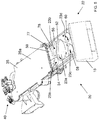
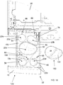
- the treating agents dispenser 20 further comprises a water distributor 35, associated to the housing 21 and placed above the drawer 22.
- the water distributor 35 preferably comprises an upper side 35a and an opposite underside 35b.
- the water distributor 35 is configured in such a way to allow the flowing of water to one or more of said compartments 23a, 23b, 23c, 23d when the drawer is placed in its closed operational position.
- the water distributor 35 preferably comprises one or more channels, not shown, adapted for selectively conveying water to one or more of said compartments 23a, 23b, 23c, 23d of the drawer 22 when the latter is placed in its closed operational position.
- the channels are provided with outlets (not shown) arranged on the underside 35b of the distributor 35 and facing the underlying compartments 23a, 23b, 23c, 23d. Outlets allow the passage of the water from the water distributor 35 to the underlying compartments 23a, 23b, 23c, 23d.
- the water distributor 35 is apt to be connected to an external water source, which could comprise, for example, the plumbing of the building in which the laundry washing machine 1 is installed.
- the external water source is preferably a source for the adduction of cold water.
- the water distributor 35 is preferably connected to the external water source by means of valves 40.
- the first compartment 23a is preferably provided with an aperture 26 defined at the rear thereof, as illustrated in Figure 7B .
- the aperture 26 is adapted to allow the flowing of a liquid therethrough and then to the bottom side 21a of the housing and the outlet port 21d to convey liquid to the supply pipe towards the tub.
- the second compartment 23b is preferably provided with an aperture 27, preferably a horizontal slot, defined at the rear thereof.
- the slot 27 is adapted to allow the flowing of a liquid therethrough and then to the bottom side 21a of the housing 21 and the outlet port 21d to convey liquid to the supply pipe towards the tub.
- the other compartments 23c and 23d of the drawer 22 are preferably provided with respective siphon tubes 24c and 24d.
- the first siphon tube 24c connects the third compartment 23c to the underside 22b of the drawer 22 and the second siphon tube 24d connects the fourth compartment 23d to the underside 22b of the drawer 22.
- Apertures 26, 27 and siphon tubes 24c, 24d define outlets apt to fluidly connecting a respective compartment 23a, 23b, 23c and 23d to the bottom side 21a of the housing 21 and the outlet port 21d.
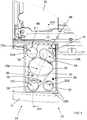
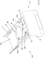
- the treating agents dispenser 20 preferably comprises a cover element 50 which is arranged between the drawer 22 and the water distributor 35.
- the cover element 50 preferably comprises an upper side 50a and an opposite underside 50b, as visible in Figure 6 .
- the upper side 50a of the cover element 50 faces the underside 35b of the water distributor 35 and the underside 50b of the cover element 50 faces the upper side 22a of the drawer 22.
- the drawer 22 comprises a border rim 22d which substantially externally delimits the compartments 23a, 23b, 23c and 23d.
- the border rim 22d preferably extends along front and lateral sides of drawer 22 while it is omitted on the rear side of the drawer 22.
- the border rim may also extend along the rear side of the drawer so as to realize a closed border.
- the cover element 50 peripherally borders the border rim 22d.
- the size of the cover element 50 is substantially equal to the size of the drawer 22.
- the width of the cover element 50 is substantially equal to the width of the drawer 22.
- the length of the cover element 50 is substantially equal to the length of the drawer 22.
- the cover element 50 has a length so that it is partially inserted in the housing 21 when the drawer 22 is in its maximum opened position.
- the length of the cover element 50 is sufficient to cover the drawer 22 when the drawer 22 is in its maximum opened position, as illustrated for example in Figure 4 .
- the rear part of the cover element 50 is advantageously partially inserted in the housing 21 and hides the underlying rear part of the drawer 22.
- the cover element 50 preferably comprises apertures 52, 54, 56, 58, 60 positioned above the compartments 23a, 23b, 23c and 23d.
- the number of apertures may be different, according to the desired type and number of treating agents which are used in the particular model of laundry washing machine.
- the cover element 50 according to the invention is apt to be positioned above the drawer 22 and slides therewith.
- the first and second apertures 52, 54 are positioned above the first compartment 23a, the third aperture 56 is positioned above the second compartment 23b, the fourth aperture 58 is positioned above the third compartment 23c and the fifth aperture 60 is positioned above the fourth compartment 23d.
- the first aperture 52 is preferably used to introduce powder detergent in the first compartment 23a.
- the second aperture 54 is preferably used to introduce a pod in the first compartment 23a.
- the user may fill the first compartment 23a through the first aperture 52 with powder detergent and/or may insert a pod in the first compartment 23a through the second aperture 54. Accordingly, during the main wash phase of the selected washing cycle, the powder detergent and/or the pod will be conveyed to the washing tub by means of water coming from the distributor 35 into the first compartment 23a passing through the first 52 and/or the second 54 aperture.
- the two apertures 52, 54 above the first compartment 23a advantageously define respective correct positions where the powder detergent or the pod is placed by the user inside the first compartment 23a.
- first aperture 52 preferably defines positioning of the powder detergent centrally in the first compartment 23a and the second aperture 54 advantageously defines positioning of the pod rearward in the first compartment 23a.
- Said positions defined by the first aperture 52 and/or the second aperture 54 preferably correspond to the best positions for the powder detergent or the pod along the direction of the water falling into the compartments from outlets of the channels on the underside 35b of the distributor 35.
- Correct positioning of the powder detergent or of the pod in the first compartment 23a assure that all, or almost all, the treating agent (detergent) is drawn through the aperture 26 into the washing tub by the water falling down from the distributor 35.
- no products accumulate at side walls of the first compartment 23a. This guarantees good hygienic conditions inside the first compartment 23a, in particular when the laundry washing machine 1 in not used for a long time between two successive washing cycles.
- the third aperture 56 is preferably used to introduce powder or liquid detergent which is preferably used during a pre-wash phase of the selected washing cycle.
- the user may fill the second compartment 23b through the third aperture 56.
- the fourth aperture 58 is preferably used to introduce liquid detergent which is preferably used during a main wash phase of the selected washing cycle.
- the user may fill the third compartment 23c through the fourth aperture 58.
- the fifth aperture 60 is preferably used to introduce liquid softener which is preferably used during a phase of the selected washing cycle.
- the user may fill the fourth compartment 23d through the fifth aperture 60.
- the apertures 56, 58, 60 above the second, third and fourth compartments 23b, 23c, 23d advantageously define respective best positions for the water falling into the compartments from outlets of the channels on the underside 35b of the distributor 35.
- Water falling down from the distributor 35 determines the best mixing action with the agent into the respective compartment.
- the first aperture 52 is opportunely shaped so as to define a boundary line 52a.
- second, third, fourth and fifth aperture 54, 56, 58, 60 are opportunely shaped so as to define a boundary line 54a, 56a, 58a, 60a.
- the boundary line 52a of the first aperture 52 is preferably smaller than the boundary line 63a of first compartment 23a, that is to say that the size of the first aperture 52 is preferably smaller than the size of first compartment 23a.
- the boundary line 54a of the second aperture 54 is smaller than the boundary line 63a of first compartment 23a, that is to say that the size of the second aperture 54 is smaller than the size of first compartment 23a.
- the boundary lines 56a, 58a, 60a of the third, fourth and fifth apertures 56, 58, 60 are smaller than the boundary line 63b, 63c and 63d of the second, third and fourth compartment 23b, 23c, 23d, that is to say that the size of the third, fourth and fifth apertures 56, 58, 60 is smaller than the size of the respective underlying compartment 23b, 23c, 23d,
- the boundary line 52a, 54a, 56a, 58a, 60a of the respective aperture 52, 54, 56, 58, 60 follows, when possible, the boundary line 63a, 63b, 63c, 63d. of the underlying compartment 23a, 23b, 23c, 23d.
- the treating agent when water is flushed from the distributor 35 into the compartment 23a, 23b, 23c, 23d through the aperture 52, 54, 56, 58, 60 the treating agent does not accumulate on the underside 50b of the cover element 50. This again guarantees good hygienic conditions.
- the power detergent when water is flushed from the distributor 35 into the first compartment 23a through the first aperture 52, the power detergent does not accumulate on the underside 50b of the cover element 50.
- the first aperture 52 comprises a rim 52b extending downwardly from the boundary line 52a. More preferably, the rim 52b extends all around the first aperture 52.
- second, third, fourth and fifth apertures 54, 56, 58, 60 each comprises a rim 54b, 56b, 58b, 60b extending downwardly from the respective boundary line 54a, 56a, 58a, 60a. More preferably, the rim 54b, 56b, 58b, 60b extends all around the aperture 54, 56, 58, 60.
- the rim 52b, 56b, 58b is preferably received in a corresponding recess 57a, 57b, 57c of the underlying compartment 23a, 23b, 23c (as depicted in Figure 16 in particular with reference to compartments 23a, 23b, 23c). More preferably, the recess 57a, 57b, 57c is defined at the upper part of lateral side walls of the compartment 23a, 23b, 23c.
- the adjoining surfaces of the cover element 50 and the compartment 23a, 23b, 23c are flush, as indicated with "S" in Figure 16 , and treating agent does not accumulated between them. This further guarantees good hygienic conditions.
- the rim is used as level indicator for indicating the level of the treating agent introduced in the underlying compartment.
- the level indicator indicates the maximum level of treating agent that should be introduced in the underlying compartment.
- the level indicator may indicate the level of treating agent introduced in the underlying compartment, for example a minimum and/or a medium level.
- the level indicator corresponds to the lower edge of the rim, as it happens for the lower edge 52c of the rim 52b of the first aperture 52a.
- the level indicator comprises a line realized in the rim of the aperture, as it happens for the rim 58b, 60b of the fourth and fifth apertures 58, 60 where a line 58c, 60c indicates the maximum level of treating agent that should be introduced in the underlying compartment 23c, 23d.
- the cover element 50 is movably associated to the upper side 22a of the drawer 22.
- the cover element 50 is removably associated to the upper side 22a of the drawer 22.
- a release device allows the cover element 50 to be realesably connected to the upper side 22a of the drawer 22.
- the release device preferably comprises elastic tongues 81a, 81b at lateral sides of the cover element 50 which are suitable to abut against side walls portions 82a, 82b of the drawer 22.
- the cover element 50 may be easily removed from the drawer 22 and then easily cleaned by the user, for example by flushing with water or by rubbing with a cloth.
- the underside 50b of the cover element 50 preferably comprises a first siphon cap 90 and a second siphon cap 94.
- the first siphon cap 90 is positioned over the siphon tube 24c of the third compartment 23c when the cover element 50 is arranged over the drawer 35.
- the second siphon cap 94 is positioned over the siphon tube 24d of the fourth compartment 23d when the cover element 50 is arranged over the drawer 35.
- the third compartment 23c and the fourth compartment 23d are used to hold and dispense liquid agents (a liquid detergent and a liquid softener, respectively).
- the third compartment 23c is preferably adapted for receiving a liquid detergent which is preferably used during a main wash phase of the selected washing cycle bleach; the fourth compartment 23d is preferably adapted for receiving a liquid softener.
- a user pours said liquid agents into compartments 23c and 23d through apertures 58, 60.
- siphoning effect As water is added to the third compartment 23c and the liquid level rises above the top of siphon tube 23c, a siphoning effect occurs. This siphon effect then draws liquid from the third compartment 23c and releases that liquid to the bottom side 21a of the housing 21 and the outlet port 21d to convey liquid to the supply pipe towards the tub.
- the first siphon cap 90 is preferably further provided with two lateral inflow tubes 91a, 91b, as depicted in Figure 14 .
- the tubes 91a, 91b extend substantially parallel to the siphon cap 90 and have a substantially equal length.
- the open ends 92a, 92b of inflow tubes 91a, 91b are angled on one side, so as to direct the inflow of water towards the base of the siphon tube/cap assembly. This arrangement is used to increase the velocity of the water output from open ends 92a, 92b.
- inflow tubes 91a, 91b allows for treating agent (detergent or softener) to be diluted more effectively.
- the inflow tubes 91a, 91b can be used to prevent/remove agent buildup at the base of the siphon tub/cap assembly. This helps ensure reliable siphon action with repeated use over time.
- the first siphon cap 90 and/or the second siphon cap 94 and/or the inflow tubes 91a, 91b are preferably integrally made with the cover element 50, more preferably by injection moulding of a plastic material.
- the upper side 50a of the cover element 50 is preferably substantially flat and the apertures are preferably realized on the same horizontal surface.
- the apertures may be realized in surfaces arranged at different levels.
- one aperture may be realized in a substantially flat surface arranged at a higher level with respect to the adjacent surfaces, where other apertures are realized.
- the fifth aperture 60 is preferably realized in a flat surface 53a which is at a higher level with respect to the adjacent surface 53b where the first 52 and fourth 58 apertures are realized.
- the levels difference between said surfaces 53a, 53b defines a small protective barrier 55 which prevents the overflow of water from adjacent surfaces.
- This feature is particularly advantageous since it avoids the siphon taking hold prior to the desired dispensing time if water accidentally flow inside the fifth aperture 60. This may happen, for example, when the drawer 22 is extracted from the housing 21 after the initial filling of treating agents in the compartments.
- Overflow of water in the fifth aperture 60 may cause a siphoning effect and softener delivery in advance with respect to the expected time for the softening phase, which is usually one of the latest phase of the washing cycle.
- the protective barrier is obtained with surfaces realized at different levels, in different embodiments the protective barrier may be differently realized, for example through a protruding rib from the upper side flat surface of the cover element.
- the upper side 50a of the cover element 50 is slightly inclined, for example 2,5° as shown in Figure 10 , with respect to the horizontal plane when the treating agents dispenser is mounted in an operational position.
- the upper side 50a of the cover element 50 is provided with a ramp sloping down towards the rear side of the drawer 22 and of the housing 21. In case water falls on the upper side 50a of the cover element 50 it may flow towards the rear side of the drawer 22 and in particular towards the outlet port 21d of the housing 21 and, from there, into the supply pipe up to the tub.
- the upper side 50a of the cover element 50 then preferably comprises one or more symbols and/or texts 88 positioned close to the compartments 23a, 23b, 23c, 23d to indicate the correct treating agent that has to be inserted in the compartments 23a, 23b, 23c, 23d.
- the cover element 50 then preferably comprises a recess 77 which allows a button 78, preferably a push button, to be easily reached by the user.
- the button 78 is advantageously actuated by the user in order to completely remove the drawer 22 from the housing 21.
- a device comprising a button to completely remove the drawer from the housing is well known in the art and therefore it will not be described in detail.
- the treating agents dispenser 120 differs from the treating agents dispenser 20 previously described with reference to Figures 1 to 16 in that the cover element 150 is characterized by a different symbol 188 positioned close to the third compartment 23c to indicate the correct treating agent that has to be inserted in the third compartment 23c.
- the first compartment 23a is still preferably adapted for receiving a powder detergent and/or a unit dose package, which is preferably used during a main wash phase of the selected washing cycle;
- the second compartment 23b is still preferably adapted for receiving a quantity of a powder or liquid detergent which is preferably used during a pre-wash phase of the selected washing cycle;
- the third compartment 23c is preferably adapted for receiving bleach;
- the fourth compartment 23d is still preferably adapted for receiving a liquid softener.
- the third compartment is preferably adapted for receiving a liquid softener and the fourth compartment is preferably adapted for receiving bleach.
- the drawer 22 underlying the cover element 150 is preferably the same above described with reference to Figures 1 to 16 .
- This embodiment does not provide for a compartment for receiving a liquid detergent usable during a main wash phase of the selected washing cycle.
- the treating agents dispenser 120 and, in particular, the first aperture 52 associated to the first compartment 23a is suitable to receive an auxiliary stand-alone liquid detergent container 160, as illustrated in Figures 18 and 19 .
- the liquid detergent container 160 is capable to store a given amount of liquid detergent product, and is properly dimensioned for being inserted in easy-removable manner into the first aperture 52.
- Liquid detergent container 160 preferably comprises a standalone basin 161 which is dimensioned for being inserted in easy-removable manner into the first aperture 52, and is provided with a syphon assembly (not shown) which is housed into basin 161 for draining out of basin 161 the liquid detergent stored in the latter when a given amount of water is channeled into the first compartment 23a through the water distributor 35, preferably in the main washing phase of the washing cycle.
- the treating agents dispenser 120 may therefore be used either for receiving a powder detergent or a liquid detergent, in the latter case by using an auxiliary stand-alone liquid detergent container 160, as illustrated in Figure 19 .
- the treating agents dispenser 220 differs from the treating agents dispenser 120 previously described with reference to Figures 17 to 19 in that the cover element 250 does not provide for the third aperture 56.
- the washing cycle does not comprise a pre-wash phase.
- the drawer 22 underlying the cover element 250 may be the same above described with reference to previous embodiments.
- the second compartment of the drawer may be omitted.
- the treating agents dispenser 320 differs from the treating agents dispenser 20 previously described with reference to Figures 17 to 19 in that the cover element 350 does not provide for the second aperture 54.
- the washing cycle does not comprise a main wash phase which uses a pod.
- the drawer 22 underlying the cover element 350 may be preferably the same above described with reference to previous embodiments.
- the treating agents dispenser 420 differs from the treating agents dispenser 120 previously described with reference to Figures 17 to 19 in that the cover element 450 does not provide for the second 54 and the third apertures 56.
- the washing cycle does not comprise a main wash phase which uses a pod and does not comprise a pre-wash phase.
- the drawer 22 underlying the cover element 450 may be the same above described with reference to previous embodiments.
- the second compartment of the drawer may be omitted.
- the treating agents dispenser 520 differs from the treating agents dispenser 20 previously described with reference to Figures 1 to 16 in that the fifth aperture 60 of the cover element 550 is preferably realized in a flat surface 553a which is at a higher level with respect to the adjacent surface 553b where the first 52, second 54, third 56 and fourth 58 apertures are realized.
- the levels difference between said surfaces 553a, 553b defines a small protective barrier 555 which prevents the overflow of water from adjacent surfaces.
- the different embodiments of the treating agents dispensers may preferably easily obtained by only substituting the cover element.
- the different embodiments of the treating agents dispensers may be manufactured utilizing the same components, except from the cover element. Manufacturing costs are therefore reduced.
- the drawer comprises four compartments, it has to be underlined that in different embodiments the number of compartments may be different, even just one.
- the shape of the compartments may be any shape suitable to receive a treating agent therewith.
- the present invention allows all the set objects to be achieved.
- it makes it possible to realize a laundry washing machine that makes it possible to reduce or prevent residues of treating agent in the treating agents dispensers.
- laundry washing machines illustrated in the enclosed figures are of the front-loading type; however it is clear that the system according to the invention can be applied as well to a top-loading laundry washing machine, substantially without any modification.
Landscapes
- Engineering & Computer Science (AREA)
- Textile Engineering (AREA)
- Detail Structures Of Washing Machines And Dryers (AREA)
Claims (15)
- Lave-linge (1) pouvant être raccordé à une source d'eau externe comprenant une enceinte (2) supportant une cuve de lavage enfermant un tambour de lavage rotatif conçu pour recevoir le linge et un distributeur d'agents de traitement (20 ; 120 ; 220 ; 320 ; 420 ; 520) pouvant être raccordé à ladite source d'eau externe et en liaison fluidique avec ladite cuve de lavage, ledit distributeur d'agents de traitement (20 ; 120 ; 220 ; 320 ; 420 ; 520) comprenant :un tiroir (22) ayant un côté supérieur (22a) comprenant un ou plusieurs compartiments (23a, 23b, 23c, 23d) à partie supérieure ouverte pour recevoir au moins un agent pour traiter le linge ;une structure de support (21) sur laquelle ledit tiroir (22) peut coulisser ;un distributeur d'eau (35) disposé au-dessus dudit tiroir (22) et comprenant au moins un canal pour acheminer l'eau de ladite source d'eau externe vers au moins un desdits un ou plusieurs compartiments (23a, 23b, 23c, 23d) dudit tiroir (22) ;caractérisé en ce queun élément couvercle (50 ; 150 ; 250 ; 350 ; 450 ; 550) est disposé entre ledit tiroir (22) et ledit distributeur d'eau (35) et ledit élément couvercle (50 ; 150 ; 250 ; 350 ; 450 ; 550) comprend au moins une ouverture (52, 54, 56, 58, 60) positionnée au-dessus d'un desdits un ou plusieurs compartiments (23a, 23b, 23c, 23d) à partie supérieure ouverte.
- Lave-linge (1) selon la revendication 1, une première ouverture (52, 54, 56, 58, 60) de ladite au moins une ouverture (52, 54, 56, 58, 60) dudit élément couvercle (50 ; 150 ; 250 ; 350 ; 450 ; 550) étant positionnée au-dessus d'un premier compartiment desdits un ou plusieurs compartiments (23a, 23b, 23c, 23d) à partie supérieure ouverte et une seconde ouverture (52, 54, 56, 58, 60) de ladite au moins une ouverture (52, 54, 56, 58, 60) dudit élément couvercle (50 ; 150 ; 250 ; 350 ; 450 ; 550) étant positionnée au-dessus d'un second compartiment desdits un ou plusieurs compartiments (23a, 23b, 23c, 23d) à partie supérieure ouverte.
- Lave-linge (1) selon la revendication 1, deux ouvertures (52, 54) de ladite au moins une ouverture (52, 54, 56, 58, 60) dudit élément couvercle (50 ; 150 ; 250 ; 550) étant positionnées au-dessus d'un premier compartiment (23a) desdits un ou plusieurs compartiments (23a, 23b, 23c, 23d) à partie supérieure ouverte.
- Lave-linge (1) selon l'une quelconque des revendications précédentes, la taille de ladite au moins une ouverture (52, 54, 56, 58, 60) étant inférieure à la taille du compartiment (23a, 23b, 23c, 23d) sous-jacent.
- Lave-linge (1) selon l'une quelconque des revendications précédentes, au moins une partie de la ligne limite (52a, 54a, 56a, 58a, 60a) de ladite au moins une ouverture (52, 54, 56, 58, 60) suivant la ligne limite (63a, 63b, 63c, 63d) du compartiment (23a, 23b, 23c, 23d) sous-jacent.
- Lave-linge (1) selon l'une quelconque des revendications précédentes, ladite au moins une ouverture (52, 54, 56, 58, 60) comprenant un bord (52b, 54b, 56b, 58b, 60b) s'étendant vers le bas depuis ladite ligne limite (52a, 54a, 56a, 58a, 60a) vers le compartiment (23a, 23b, 23c, 23d) sous-jacent.
- Lave-linge (1) selon les revendications 6 et 5, au moins une partie dudit bord (52b, 56b, 58b) étant reçue dans un évidement (57a, 57b, 57c) dudit compartiment (23a, 23b, 23c) sous-jacent.
- Lave-linge (1) selon l'une quelconque des revendications précédentes, ledit élément couvercle (50 ; 150 ; 250 ; 350 ; 450 ; 550) comprenant au moins un indicateur de niveau pour ledit au moins un agent de traitement.
- Lave-linge (1) selon l'une quelconque des revendications précédentes, ledit tiroir (22) comprenant un bord de bordure (22d) qui délimite au moins partiellement extérieurement lesdits compartiments (23a, 23b, 23c, 23d) et ledit élément couvercle (50 ; 150 ; 250 ; 350 ; 450 ; 550) bordant périphériquement ledit bord de bordure (22d).
- Lave-linge (1) selon l'une quelconque des revendications précédentes, ledit élément couvercle (50 ; 150 ; 250 ; 350 ; 450 ; 550) ayant une longueur telle qu'il est partiellement inséré dans ladite structure de support (21) lorsque le tiroir (22) est dans sa position ouverte maximale.
- Lave-linge (1) selon l'une quelconque des revendications précédentes, ledit élément couvercle (50 ; 150 ; 250 ; 350 ; 450 ; 550) étant relié amovible audit côté supérieur (22a) dudit tiroir (22).
- Lave-linge (1) selon l'une quelconque des revendications précédentes, une première de ladite au moins une ouverture (52, 54, 56, 58, 60) étant réalisée dans une première surface (53a ; 553a) d'un côté supérieur (50a) dudit élément couvercle (50 ; 150 ; 250 ; 350 ; 450 ; 550) et une seconde de ladite au moins une ouverture (52, 54, 56, 58, 60) étant réalisée dans une seconde surface (53b ; 553b) dudit côté supérieur (50a) dudit élément couvercle (50 ; 150 ; 250 ; 350 ; 450 ; 550), ladite première surface (53a ; 553a) étant à un niveau différent par rapport à ladite seconde surface (53b ; 553b).
- Lave-linge (1) selon l'une quelconque des revendications précédentes, une première de ladite au moins une ouverture (52, 54, 56, 58, 60) étant réalisée dans une première surface (53a ; 553a) d'un côté supérieur (50a) dudit élément couvercle (50 ; 150 ; 250 ; 350 ; 450 ; 550) et une seconde de ladite au moins une ouverture (52, 54, 56, 58, 60) étant réalisée dans une seconde surface (53b ; 553b) dudit côté supérieur (50a) dudit élément couvercle (50 ; 150 ; 250 ; 350 ; 450 ; 550), ladite première surface (53a ; 553a) et ladite seconde surface (53b ; 553b) étant séparées par une barrière de protection (55 ; 555).
- Lave-linge(1) selon l'une quelconque des revendications précédentes, au moins un desdits un ou plusieurs compartiments (23a, 23b, 23c, 23d) comprenant une sortie permettant de relier fluidiquement ledit au moins un desdits un ou plusieurs compartiments (23a, 23b, 23c, 23d) à un côté inférieur (22b) dudit tiroir (22).
- Lave-linge (1) selon l'une quelconque des revendications précédentes, un côté inférieur (50b) dudit élément couvercle (50 ; 150 ; 250 ; 350 ; 450 ; 550) comprenant un siphon de couvercle (90, 94).
Priority Applications (10)
| Application Number | Priority Date | Filing Date | Title |
|---|---|---|---|
| PL21167800.8T PL3882392T3 (pl) | 2016-09-05 | 2016-09-05 | Sposób stosowania pralki do rzeczy pranych i pralka do rzeczy pranych |
| EP21167800.8A EP3882392B1 (fr) | 2016-09-05 | 2016-09-05 | Procédé d'utilisation d'une machine à laver et machine à laver |
| EP19155280.1A EP3511465B1 (fr) | 2016-09-05 | 2016-09-05 | Machine à laver le linge équipée d'un distributeur d'agents de traitement |
| EP16187291.6A EP3290568B1 (fr) | 2016-09-05 | 2016-09-05 | Lave-linge avec un distributeur de detergent |
| PL16187291T PL3290568T3 (pl) | 2016-09-05 | 2016-09-05 | Pralka do materiałów pranych z dozownikiem detergentu |
| PL19155280T PL3511465T3 (pl) | 2016-09-05 | 2016-09-05 | Pralka wyposażona w dozownik środków do obróbki |
| US16/329,831 US11255038B2 (en) | 2016-09-05 | 2017-08-23 | Laundry washing machine equipped with a treating agents dispenser |
| CN201780052899.3A CN109689961B (zh) | 2016-09-05 | 2017-08-23 | 配备有处理试剂分配器的洗衣机 |
| PCT/EP2017/071182 WO2018041682A1 (fr) | 2016-09-05 | 2017-08-23 | Machine à laver le linge munie d'un distributeur d'agents de traitement |
| BR112019002048-9A BR112019002048B1 (pt) | 2016-09-05 | 2017-08-23 | Máquina de lavar roupas equipada com um dispensador de agentes de tratamento |
Applications Claiming Priority (1)
| Application Number | Priority Date | Filing Date | Title |
|---|---|---|---|
| EP16187291.6A EP3290568B1 (fr) | 2016-09-05 | 2016-09-05 | Lave-linge avec un distributeur de detergent |
Related Child Applications (3)
| Application Number | Title | Priority Date | Filing Date |
|---|---|---|---|
| EP19155280.1A Division-Into EP3511465B1 (fr) | 2016-09-05 | 2016-09-05 | Machine à laver le linge équipée d'un distributeur d'agents de traitement |
| EP19155280.1A Division EP3511465B1 (fr) | 2016-09-05 | 2016-09-05 | Machine à laver le linge équipée d'un distributeur d'agents de traitement |
| EP21167800.8A Division EP3882392B1 (fr) | 2016-09-05 | 2016-09-05 | Procédé d'utilisation d'une machine à laver et machine à laver |
Publications (2)
| Publication Number | Publication Date |
|---|---|
| EP3290568A1 EP3290568A1 (fr) | 2018-03-07 |
| EP3290568B1 true EP3290568B1 (fr) | 2019-03-20 |
Family
ID=56855387
Family Applications (3)
| Application Number | Title | Priority Date | Filing Date |
|---|---|---|---|
| EP19155280.1A Active EP3511465B1 (fr) | 2016-09-05 | 2016-09-05 | Machine à laver le linge équipée d'un distributeur d'agents de traitement |
| EP16187291.6A Revoked EP3290568B1 (fr) | 2016-09-05 | 2016-09-05 | Lave-linge avec un distributeur de detergent |
| EP21167800.8A Active EP3882392B1 (fr) | 2016-09-05 | 2016-09-05 | Procédé d'utilisation d'une machine à laver et machine à laver |
Family Applications Before (1)
| Application Number | Title | Priority Date | Filing Date |
|---|---|---|---|
| EP19155280.1A Active EP3511465B1 (fr) | 2016-09-05 | 2016-09-05 | Machine à laver le linge équipée d'un distributeur d'agents de traitement |
Family Applications After (1)
| Application Number | Title | Priority Date | Filing Date |
|---|---|---|---|
| EP21167800.8A Active EP3882392B1 (fr) | 2016-09-05 | 2016-09-05 | Procédé d'utilisation d'une machine à laver et machine à laver |
Country Status (5)
| Country | Link |
|---|---|
| US (1) | US11255038B2 (fr) |
| EP (3) | EP3511465B1 (fr) |
| CN (1) | CN109689961B (fr) |
| PL (3) | PL3290568T3 (fr) |
| WO (1) | WO2018041682A1 (fr) |
Cited By (1)
| Publication number | Priority date | Publication date | Assignee | Title |
|---|---|---|---|---|
| EP3882392A1 (fr) | 2016-09-05 | 2021-09-22 | Electrolux Appliances Aktiebolag | Procédé d'utilisation d'une machine à laver et machine à laver |
Families Citing this family (5)
| Publication number | Priority date | Publication date | Assignee | Title |
|---|---|---|---|---|
| US10988889B2 (en) | 2018-09-24 | 2021-04-27 | Haier Us Appliance Solutions, Inc. | Additive dispenser for dissolving an additive pod within a washing appliance |
| JP7142211B2 (ja) * | 2019-04-09 | 2022-09-27 | パナソニックIpマネジメント株式会社 | 洗濯機 |
| US11280041B2 (en) | 2020-01-23 | 2022-03-22 | Haier Us Appliance Solutions, Inc. | Additive dispenser for varying the types of additives within a washing machine appliance |
| US11447908B2 (en) * | 2020-02-13 | 2022-09-20 | Haier Us Appliance Solutions, Inc. | Additive dispenser for varying the types of additives within a washing machine appliance |
| US11920280B2 (en) | 2022-03-04 | 2024-03-05 | Haier Us Appliance Solutions, Inc. | Washing machine appliance and scent-infusing assembly |
Citations (62)
| Publication number | Priority date | Publication date | Assignee | Title |
|---|---|---|---|---|
| GB306073A (en) | 1928-02-15 | 1929-06-06 | Jur Bruno Hilliger | Improvements relating to washing machines |
| GB865208A (en) | 1956-04-18 | 1961-04-12 | Marchon Products Ltd | Improvements in or relating to detergent dispensers |
| GB1264739A (fr) | 1969-07-09 | 1972-02-23 | ||
| DE2143980A1 (de) | 1971-09-02 | 1973-03-08 | Walther Horst Dipl Ing | 8vorrichtung zur zerstoerung von schaum, insbesondere waschmittelschaum |
| GB1402366A (en) | 1973-02-23 | 1975-08-06 | Wilkins & Mitchell Ltd | Clothes washing machine |
| EP0327043B1 (fr) | 1988-02-02 | 1992-11-19 | MERLONI ELETTRODOMESTICI S.p.A. | Bac distributeur de détergent pour machines à laver |
| KR920010992B1 (ko) | 1990-05-04 | 1992-12-26 | 삼성전자 주식회사 | 세탁기의 세제거품 제거장치 및 그 방법 |
| US5375438A (en) | 1992-11-11 | 1994-12-27 | Zanussi Elettrodomestici S.P.A. | Water inlet arrangement for washing machines |
| GB2297561A (en) | 1995-02-03 | 1996-08-07 | Bosch Siemens Hausgeraete | Water feed equipment for an apliance operable with water |
| JPH10156337A (ja) | 1996-11-28 | 1998-06-16 | Nikken Corp | 屎尿処理装置の消泡機構 |
| JPH10272303A (ja) | 1997-04-01 | 1998-10-13 | Yoshikawa Enbi Kogyosho:Kk | 消泡機および消泡機を用いたごみ・泡除去装置 |
| DE20211363U1 (de) | 2002-05-25 | 2002-09-26 | Whirlpool Corp., Benton Harbor, Mich. | Waschmittel-Einspülschale für eine Waschmaschine |
| WO2003078357A1 (fr) | 2002-03-19 | 2003-09-25 | Electrolux Home Products Corporation N.V. | Distributeur d'aide au lavage et lave-linge comprenant ledit distributeur |
| EP1561853A1 (fr) | 2004-02-06 | 2005-08-10 | Lg Electronics Inc. | Structure pour empêcher l'écoulement de fluide dans une machine à laver |
| EP1607509A1 (fr) | 2004-06-15 | 2005-12-21 | Samsung Electronics Co., Ltd. | Machine à laver avec distributeur de détergent |
| EP1607510A1 (fr) | 2004-06-15 | 2005-12-21 | Samsung Electronics Co., Ltd. | Lave-linge avec un distributeur de détergent |
| JP2006006676A (ja) | 2004-06-28 | 2006-01-12 | Hitachi Home & Life Solutions Inc | 洗濯乾燥機 |
| CN2830466Y (zh) | 2005-05-26 | 2006-10-25 | 海尔集团公司 | 洗衣机用洗涤剂盒 |
| CN1869317A (zh) | 2005-05-25 | 2006-11-29 | 海尔集团公司 | 洗衣机用洗涤剂盒 |
| EP1760187A1 (fr) | 2005-08-30 | 2007-03-07 | Samsung Electronics Co., Ltd. | Bac pour détergents pour une machine à laver |
| EP1764437A1 (fr) | 2005-09-16 | 2007-03-21 | Whirlpool Corporation | Distributeur de détergent pour une machine à laver le linge |
| WO2007071583A2 (fr) | 2005-12-19 | 2007-06-28 | Arcelik Anonim Sirketi | Machine à laver |
| CN101168913A (zh) | 2006-10-23 | 2008-04-30 | 南京乐金熊猫电器有限公司 | 洗衣机的洗涤剂箱 |
| CN101177894A (zh) | 2006-11-08 | 2008-05-14 | 南京乐金熊猫电器有限公司 | 洗涤装置的洗涤剂供给机构 |
| CN101177896A (zh) | 2006-11-08 | 2008-05-14 | 南京乐金熊猫电器有限公司 | 一种洗涤装置的洗涤剂供给机构 |
| US20090053119A1 (en) | 2007-08-20 | 2009-02-26 | Whirlpool Corporation | Agent dispenser |
| CN101457462A (zh) | 2008-12-26 | 2009-06-17 | 南京乐金熊猫电器有限公司 | 液体洗涤剂及纤维柔顺剂盒组件以及洗涤剂分配器 |
| JP2009261753A (ja) | 2008-04-28 | 2009-11-12 | Panasonic Corp | 洗濯機 |
| US20100095712A1 (en) | 2008-10-17 | 2010-04-22 | Bo Yeon Kim | Fluid detergent and fabric softner box assembly for laundry machine and detergent dispenser having the same |
| KR20100055206A (ko) | 2008-11-17 | 2010-05-26 | 엘지전자 주식회사 | 세탁물 처리기기 |
| KR20100055207A (ko) | 2008-11-17 | 2010-05-26 | 엘지전자 주식회사 | 세탁물 처리기기 |
| KR20100055214A (ko) | 2008-11-17 | 2010-05-26 | 엘지전자 주식회사 | 세탁기 |
| US20100300157A1 (en) | 2007-05-11 | 2010-12-02 | BSH Bosch und Siemens Hausgeräte GmbH | Automatically controlled washing machine |
| US20110067456A1 (en) | 2009-09-21 | 2011-03-24 | Alliance Laundry Systems Llc | Washer extractor with improved chemical dispenser |
| DE102009029446A1 (de) | 2009-09-14 | 2011-03-24 | BSH Bosch und Siemens Hausgeräte GmbH | Wasserführendes Haushaltsgerät |
| WO2011047451A1 (fr) | 2009-10-21 | 2011-04-28 | Whirpool S.A. | Distributeur de détergent pour lave-linge |
| EP2325376A1 (fr) | 2009-11-24 | 2011-05-25 | Samsung Electronics Co., Ltd. | Appareil de fourniture de détergent et machine à laver dotée de celui-ci |
| WO2011080088A2 (fr) | 2009-12-30 | 2011-07-07 | Arcelik Anonim Sirketi | Machine à laver comportant une boîte de produit de lavage |
| EP2372011A1 (fr) | 2010-03-31 | 2011-10-05 | Electrolux Home Products Corporation N.V. | Ensemble de tiroirs |
| EP2374927A2 (fr) | 2008-11-17 | 2011-10-12 | LG Electronics Inc. | Lave-linge |
| CN102230269A (zh) | 2011-06-16 | 2011-11-02 | 杭州神林电子有限公司 | 上投式液体洗涤剂投放装置 |
| WO2012025332A2 (fr) | 2010-08-26 | 2012-03-01 | Unilever Plc | Dispositif de distribution |
| WO2012084479A2 (fr) | 2010-12-24 | 2012-06-28 | Arcelik Anonim Sirketi | Machine à laver qui comprend un distributeur de produit chimique de lavage |
| WO2012085827A2 (fr) | 2010-12-21 | 2012-06-28 | Indesit Company S.P.A. | Appareil ménager électrique |
| WO2012084495A2 (fr) | 2010-12-24 | 2012-06-28 | Arcelik Anonim Sirketi | Machine à laver qui comprend un distributeur |
| US20120174632A1 (en) | 2011-01-12 | 2012-07-12 | Korea University Research And Business Foundation | Detergent case and washing machine having the same |
| CN102605588A (zh) | 2011-09-26 | 2012-07-25 | 南京乐金熊猫电器有限公司 | 洗涤剂分配器及设置有洗涤剂分配器的衣物处理装置 |
| EP2503049A1 (fr) | 2011-03-25 | 2012-09-26 | Miele & Cie. KG | Dispositif de rinçage pour un lave-linge doté d'un tiroir agencé dans un compartiment d'introduction |
| CN102776751A (zh) | 2011-05-10 | 2012-11-14 | 海尔集团公司 | 洗衣机洗涤剂添加装置及使用该装置的洗衣机和洗衣方法 |
| WO2013032224A2 (fr) | 2011-09-02 | 2013-03-07 | Lg Electronics Inc. | Lave-linge |
| EP2460925B1 (fr) | 2010-12-01 | 2014-01-22 | Primus CE, s.r.o. | dispositif doseur |
| EP2703545A2 (fr) | 2012-08-27 | 2014-03-05 | Samsung Electronics Co., Ltd. | Machine à laver ayant un dispositif d'alimentation en détergent |
| US20140190216A1 (en) | 2013-01-07 | 2014-07-10 | General Electric Company | Pedestal in dispenser cups of a washing machine |
| CN104358076A (zh) | 2014-11-17 | 2015-02-18 | 广东格兰仕集团有限公司 | 洗衣机的洗衣液盒组件 |
| WO2015065301A1 (fr) | 2013-11-01 | 2015-05-07 | Arcelik Anonim Sirketi | Machine à laver comprenant un distributeur d'agent de nettoyage |
| WO2015096407A1 (fr) | 2013-12-27 | 2015-07-02 | 海尔集团公司 | Base de panneau de commande de machine à laver à fonction d'ajout automatique de détergent |
| EP2048275B1 (fr) | 2007-10-10 | 2015-08-05 | Electrolux Home Products Corporation N.V. | Distributeur de produits détergents et similaires de lave-linge |
| EP2604743B1 (fr) | 2011-12-14 | 2015-08-12 | Electrolux Home Products Corporation N.V. | Machine à laver le linge |
| US20150247276A1 (en) | 2014-01-29 | 2015-09-03 | Samsung Electronics Co., Ltd. | Washing machine and washing water supply device |
| US20160047077A1 (en) | 2014-08-12 | 2016-02-18 | General Electric Company | Nozzle formed in a dispensing apparatus |
| CN105568631A (zh) | 2014-10-15 | 2016-05-11 | 苏州三星电子有限公司 | 洗衣机及其柔顺剂盒 |
| WO2016084284A1 (fr) | 2014-11-26 | 2016-06-02 | パナソニックIpマネジメント株式会社 | Machine à laver |
Family Cites Families (22)
| Publication number | Priority date | Publication date | Assignee | Title |
|---|---|---|---|---|
| DD159789A1 (de) | 1981-06-22 | 1983-04-06 | Diethold Just | Automatische dosiereinrichtung fuer bleichmittel in waschmaschinen |
| DE3614621A1 (de) | 1986-04-30 | 1987-11-05 | Puttfarcken Ulf | Reinigungsmittel-dosiervorrichtung fuer geschirrspueler |
| US20020088502A1 (en) | 2000-10-04 | 2002-07-11 | Van Rompuy Tanya Cecile Corneel | Smart dosing device |
| US7086110B2 (en) | 2002-02-13 | 2006-08-08 | The Procter & Gamble Company | Selective dispensing of laundry additives during automatic machine laundering of fabric |
| KR101082561B1 (ko) | 2004-04-14 | 2011-11-10 | 엘지전자 주식회사 | 세탁기의 세제 공급장치 |
| KR101203554B1 (ko) * | 2005-06-29 | 2012-11-21 | 엘지전자 주식회사 | 세정장치의 세제공급기구 |
| CN1868317A (zh) | 2006-06-20 | 2006-11-29 | 武全宝 | 一种方便面的生产方法 |
| CN101177899A (zh) | 2006-11-08 | 2008-05-14 | 南京乐金熊猫电器有限公司 | 洗涤装置的洗涤剂供给机构 |
| DE102007028173A1 (de) | 2007-06-20 | 2008-12-24 | BSH Bosch und Siemens Hausgeräte GmbH | Automatisch gesteuerte Waschmaschine |
| US9085844B2 (en) * | 2007-11-13 | 2015-07-21 | Electrolux Home Products, Inc. | Sequenced water delivery in an additive dispenser |
| DE102008026052A1 (de) | 2008-05-30 | 2009-12-03 | Lothar Ernst Wilhelm Weber | Waschmittel u. a. |
| US8348361B2 (en) * | 2008-06-30 | 2013-01-08 | Electrolux Home Products, Inc. | Additive dispenser drawer assembly |
| EP2241669B1 (fr) * | 2009-04-09 | 2014-06-18 | Electrolux Home Products Corporation N.V. | Machine à laver avec un circuit d'entrée de liquide de nettoyage/rinçage amélioré |
| PL2365120T3 (pl) | 2010-03-09 | 2012-07-31 | Miele & Cie | Pralka ze zbiornikiem przepływowym i wyjmowalnym pojemnikiem |
| ES2530072T3 (es) | 2011-11-22 | 2015-02-26 | Miele & Cie. Kg | Máquina lavadora con un dispositivo dispensador y un receptáculo insertable |
| ITRN20110087A1 (it) | 2011-12-22 | 2013-06-23 | Indesit Co Spa | Elettrodomestico. |
| KR101940245B1 (ko) | 2012-11-20 | 2019-01-18 | 엘지전자 주식회사 | 세탁물 처리기기 |
| MX358638B (es) * | 2013-05-31 | 2018-08-29 | Mabe Sa De Cv | Despachador automatico de aditivos cloro y jabon. |
| DE102013106107A1 (de) | 2013-06-12 | 2014-12-18 | Miele & Cie. Kg | Waschmaschine mit einem Waschmitteleinspülkasten |
| CN203795188U (zh) | 2014-02-11 | 2014-08-27 | 惠而浦(中国)投资有限公司 | 一种洗衣机用自动投放洗涤剂系统 |
| EP3037582A1 (fr) | 2014-12-23 | 2016-06-29 | Indesit Company S.p.A. | Accessoire applicable à un appareil électroménager pour laver du linge et appareil électroménager comprenant l'accessoire |
| PL3290568T3 (pl) | 2016-09-05 | 2019-09-30 | Electrolux Appliances Aktiebolag | Pralka do materiałów pranych z dozownikiem detergentu |
-
2016
- 2016-09-05 PL PL16187291T patent/PL3290568T3/pl unknown
- 2016-09-05 PL PL21167800.8T patent/PL3882392T3/pl unknown
- 2016-09-05 EP EP19155280.1A patent/EP3511465B1/fr active Active
- 2016-09-05 EP EP16187291.6A patent/EP3290568B1/fr not_active Revoked
- 2016-09-05 PL PL19155280T patent/PL3511465T3/pl unknown
- 2016-09-05 EP EP21167800.8A patent/EP3882392B1/fr active Active
-
2017
- 2017-08-23 CN CN201780052899.3A patent/CN109689961B/zh active Active
- 2017-08-23 US US16/329,831 patent/US11255038B2/en active Active
- 2017-08-23 WO PCT/EP2017/071182 patent/WO2018041682A1/fr not_active Ceased
Patent Citations (64)
| Publication number | Priority date | Publication date | Assignee | Title |
|---|---|---|---|---|
| GB306073A (en) | 1928-02-15 | 1929-06-06 | Jur Bruno Hilliger | Improvements relating to washing machines |
| GB865208A (en) | 1956-04-18 | 1961-04-12 | Marchon Products Ltd | Improvements in or relating to detergent dispensers |
| GB1264739A (fr) | 1969-07-09 | 1972-02-23 | ||
| DE2143980A1 (de) | 1971-09-02 | 1973-03-08 | Walther Horst Dipl Ing | 8vorrichtung zur zerstoerung von schaum, insbesondere waschmittelschaum |
| GB1402366A (en) | 1973-02-23 | 1975-08-06 | Wilkins & Mitchell Ltd | Clothes washing machine |
| EP0327043B1 (fr) | 1988-02-02 | 1992-11-19 | MERLONI ELETTRODOMESTICI S.p.A. | Bac distributeur de détergent pour machines à laver |
| KR920010992B1 (ko) | 1990-05-04 | 1992-12-26 | 삼성전자 주식회사 | 세탁기의 세제거품 제거장치 및 그 방법 |
| US5375438A (en) | 1992-11-11 | 1994-12-27 | Zanussi Elettrodomestici S.P.A. | Water inlet arrangement for washing machines |
| GB2297561A (en) | 1995-02-03 | 1996-08-07 | Bosch Siemens Hausgeraete | Water feed equipment for an apliance operable with water |
| JPH10156337A (ja) | 1996-11-28 | 1998-06-16 | Nikken Corp | 屎尿処理装置の消泡機構 |
| JPH10272303A (ja) | 1997-04-01 | 1998-10-13 | Yoshikawa Enbi Kogyosho:Kk | 消泡機および消泡機を用いたごみ・泡除去装置 |
| WO2003078357A1 (fr) | 2002-03-19 | 2003-09-25 | Electrolux Home Products Corporation N.V. | Distributeur d'aide au lavage et lave-linge comprenant ledit distributeur |
| DE20211363U1 (de) | 2002-05-25 | 2002-09-26 | Whirlpool Corp., Benton Harbor, Mich. | Waschmittel-Einspülschale für eine Waschmaschine |
| EP1561853A1 (fr) | 2004-02-06 | 2005-08-10 | Lg Electronics Inc. | Structure pour empêcher l'écoulement de fluide dans une machine à laver |
| EP1607509A1 (fr) | 2004-06-15 | 2005-12-21 | Samsung Electronics Co., Ltd. | Machine à laver avec distributeur de détergent |
| EP1607510A1 (fr) | 2004-06-15 | 2005-12-21 | Samsung Electronics Co., Ltd. | Lave-linge avec un distributeur de détergent |
| JP2006006676A (ja) | 2004-06-28 | 2006-01-12 | Hitachi Home & Life Solutions Inc | 洗濯乾燥機 |
| CN1869317A (zh) | 2005-05-25 | 2006-11-29 | 海尔集团公司 | 洗衣机用洗涤剂盒 |
| CN2830466Y (zh) | 2005-05-26 | 2006-10-25 | 海尔集团公司 | 洗衣机用洗涤剂盒 |
| EP1760187A1 (fr) | 2005-08-30 | 2007-03-07 | Samsung Electronics Co., Ltd. | Bac pour détergents pour une machine à laver |
| EP1764437A1 (fr) | 2005-09-16 | 2007-03-21 | Whirlpool Corporation | Distributeur de détergent pour une machine à laver le linge |
| WO2007071583A2 (fr) | 2005-12-19 | 2007-06-28 | Arcelik Anonim Sirketi | Machine à laver |
| CN101168913A (zh) | 2006-10-23 | 2008-04-30 | 南京乐金熊猫电器有限公司 | 洗衣机的洗涤剂箱 |
| CN101177894A (zh) | 2006-11-08 | 2008-05-14 | 南京乐金熊猫电器有限公司 | 洗涤装置的洗涤剂供给机构 |
| CN101177896A (zh) | 2006-11-08 | 2008-05-14 | 南京乐金熊猫电器有限公司 | 一种洗涤装置的洗涤剂供给机构 |
| US20100300157A1 (en) | 2007-05-11 | 2010-12-02 | BSH Bosch und Siemens Hausgeräte GmbH | Automatically controlled washing machine |
| US20090053119A1 (en) | 2007-08-20 | 2009-02-26 | Whirlpool Corporation | Agent dispenser |
| EP2048275B1 (fr) | 2007-10-10 | 2015-08-05 | Electrolux Home Products Corporation N.V. | Distributeur de produits détergents et similaires de lave-linge |
| JP2009261753A (ja) | 2008-04-28 | 2009-11-12 | Panasonic Corp | 洗濯機 |
| US20100095712A1 (en) | 2008-10-17 | 2010-04-22 | Bo Yeon Kim | Fluid detergent and fabric softner box assembly for laundry machine and detergent dispenser having the same |
| KR20100055214A (ko) | 2008-11-17 | 2010-05-26 | 엘지전자 주식회사 | 세탁기 |
| KR20100055207A (ko) | 2008-11-17 | 2010-05-26 | 엘지전자 주식회사 | 세탁물 처리기기 |
| KR20100055206A (ko) | 2008-11-17 | 2010-05-26 | 엘지전자 주식회사 | 세탁물 처리기기 |
| EP2374927A2 (fr) | 2008-11-17 | 2011-10-12 | LG Electronics Inc. | Lave-linge |
| CN101457462A (zh) | 2008-12-26 | 2009-06-17 | 南京乐金熊猫电器有限公司 | 液体洗涤剂及纤维柔顺剂盒组件以及洗涤剂分配器 |
| DE102009029446A1 (de) | 2009-09-14 | 2011-03-24 | BSH Bosch und Siemens Hausgeräte GmbH | Wasserführendes Haushaltsgerät |
| US20110067456A1 (en) | 2009-09-21 | 2011-03-24 | Alliance Laundry Systems Llc | Washer extractor with improved chemical dispenser |
| WO2011047451A1 (fr) | 2009-10-21 | 2011-04-28 | Whirpool S.A. | Distributeur de détergent pour lave-linge |
| EP2325376A1 (fr) | 2009-11-24 | 2011-05-25 | Samsung Electronics Co., Ltd. | Appareil de fourniture de détergent et machine à laver dotée de celui-ci |
| WO2011080088A2 (fr) | 2009-12-30 | 2011-07-07 | Arcelik Anonim Sirketi | Machine à laver comportant une boîte de produit de lavage |
| EP2372011A1 (fr) | 2010-03-31 | 2011-10-05 | Electrolux Home Products Corporation N.V. | Ensemble de tiroirs |
| WO2012025332A2 (fr) | 2010-08-26 | 2012-03-01 | Unilever Plc | Dispositif de distribution |
| EP2460925B1 (fr) | 2010-12-01 | 2014-01-22 | Primus CE, s.r.o. | dispositif doseur |
| WO2012085827A2 (fr) | 2010-12-21 | 2012-06-28 | Indesit Company S.P.A. | Appareil ménager électrique |
| WO2012085843A2 (fr) | 2010-12-21 | 2012-06-28 | Indesit Company S.P.A. | Appareil ménager électrique doté d'un panneau rotatif |
| WO2012084479A2 (fr) | 2010-12-24 | 2012-06-28 | Arcelik Anonim Sirketi | Machine à laver qui comprend un distributeur de produit chimique de lavage |
| WO2012084495A2 (fr) | 2010-12-24 | 2012-06-28 | Arcelik Anonim Sirketi | Machine à laver qui comprend un distributeur |
| US20120174632A1 (en) | 2011-01-12 | 2012-07-12 | Korea University Research And Business Foundation | Detergent case and washing machine having the same |
| EP2503049A1 (fr) | 2011-03-25 | 2012-09-26 | Miele & Cie. KG | Dispositif de rinçage pour un lave-linge doté d'un tiroir agencé dans un compartiment d'introduction |
| CN102776751A (zh) | 2011-05-10 | 2012-11-14 | 海尔集团公司 | 洗衣机洗涤剂添加装置及使用该装置的洗衣机和洗衣方法 |
| CN102230269A (zh) | 2011-06-16 | 2011-11-02 | 杭州神林电子有限公司 | 上投式液体洗涤剂投放装置 |
| US20140190220A1 (en) | 2011-09-02 | 2014-07-10 | Lg Electronics Inc. | Washing machine |
| WO2013032224A2 (fr) | 2011-09-02 | 2013-03-07 | Lg Electronics Inc. | Lave-linge |
| CN102605588A (zh) | 2011-09-26 | 2012-07-25 | 南京乐金熊猫电器有限公司 | 洗涤剂分配器及设置有洗涤剂分配器的衣物处理装置 |
| EP2604743B1 (fr) | 2011-12-14 | 2015-08-12 | Electrolux Home Products Corporation N.V. | Machine à laver le linge |
| EP2703545A2 (fr) | 2012-08-27 | 2014-03-05 | Samsung Electronics Co., Ltd. | Machine à laver ayant un dispositif d'alimentation en détergent |
| US20140190216A1 (en) | 2013-01-07 | 2014-07-10 | General Electric Company | Pedestal in dispenser cups of a washing machine |
| WO2015065301A1 (fr) | 2013-11-01 | 2015-05-07 | Arcelik Anonim Sirketi | Machine à laver comprenant un distributeur d'agent de nettoyage |
| WO2015096407A1 (fr) | 2013-12-27 | 2015-07-02 | 海尔集团公司 | Base de panneau de commande de machine à laver à fonction d'ajout automatique de détergent |
| US20150247276A1 (en) | 2014-01-29 | 2015-09-03 | Samsung Electronics Co., Ltd. | Washing machine and washing water supply device |
| US20160047077A1 (en) | 2014-08-12 | 2016-02-18 | General Electric Company | Nozzle formed in a dispensing apparatus |
| CN105568631A (zh) | 2014-10-15 | 2016-05-11 | 苏州三星电子有限公司 | 洗衣机及其柔顺剂盒 |
| CN104358076A (zh) | 2014-11-17 | 2015-02-18 | 广东格兰仕集团有限公司 | 洗衣机的洗衣液盒组件 |
| WO2016084284A1 (fr) | 2014-11-26 | 2016-06-02 | パナソニックIpマネジメント株式会社 | Machine à laver |
Non-Patent Citations (3)
| Title |
|---|
| HOTPOINT ARISTON: "Lavasciuga ARMXL 129", USER MANUAL, January 2008 (2008-01-01), pages 1 - 12, XP055660038 |
| INDESIT: "Lavabiancheria PWE 8108 W", USER MANUAL, February 2009 (2009-02-01), pages 1 - 12, XP055660035 |
| INDESIT: "Lavasciuga IWDC 6105", USER MANUAL, November 2008 (2008-11-01), pages 1 - 12, XP055660043 |
Cited By (1)
| Publication number | Priority date | Publication date | Assignee | Title |
|---|---|---|---|---|
| EP3882392A1 (fr) | 2016-09-05 | 2021-09-22 | Electrolux Appliances Aktiebolag | Procédé d'utilisation d'une machine à laver et machine à laver |
Also Published As
| Publication number | Publication date |
|---|---|
| WO2018041682A1 (fr) | 2018-03-08 |
| EP3882392B1 (fr) | 2024-08-21 |
| EP3511465B1 (fr) | 2021-11-10 |
| US20190226138A1 (en) | 2019-07-25 |
| EP3290568A1 (fr) | 2018-03-07 |
| BR112019002048A2 (pt) | 2019-05-07 |
| US11255038B2 (en) | 2022-02-22 |
| EP3882392A1 (fr) | 2021-09-22 |
| CN109689961B (zh) | 2021-08-31 |
| CN109689961A (zh) | 2019-04-26 |
| EP3511465A1 (fr) | 2019-07-17 |
| PL3882392T3 (pl) | 2025-01-07 |
| PL3290568T3 (pl) | 2019-09-30 |
| PL3511465T3 (pl) | 2022-04-04 |
Similar Documents
| Publication | Publication Date | Title |
|---|---|---|
| EP3290568B1 (fr) | Lave-linge avec un distributeur de detergent | |
| US10422073B2 (en) | Laundry washing machine equipped with a treating agents dispenser having water supplying apparatus | |
| US9644308B2 (en) | Nozzle formed in a dispensing apparatus | |
| US10132023B2 (en) | Household cleaning appliance with a dispensing system operable between a single use dispensing system and a bulk dispensing system | |
| US9027370B2 (en) | Fluid additive dispenser | |
| US20050229652A1 (en) | Apparatus for supplying detergent in washer | |
| US10138587B2 (en) | Household cleaning appliance with a dispensing system operable between a single use dispensing system and a bulk dispensing system | |
| US20120125055A1 (en) | Detergent supply device and washing machine having the same | |
| EP3786336B1 (fr) | Dispositif d'alimentation en détergent | |
| US9127391B2 (en) | Device for dispensing an additive in an appliance | |
| EP2133456B1 (fr) | Machine à laver et/ou sécher avec distributeur de détergent multifonction, et procédé de fonctionnement relatif | |
| US20170298562A1 (en) | Washing Machine Appliance with a Fluid Additive Receptacle | |
| EP3044359B1 (fr) | Distributeur de produit de nettoyage comportant une structure supérieure | |
| KR101474433B1 (ko) | 세탁기의 세제 공급 장치 | |
| US20130186151A1 (en) | Appliance with features for preventing additive drying | |
| EP3272930B1 (fr) | Machine à laver le linge équipée d'un distributeur d'agents de traitement | |
| BR112019002048B1 (pt) | Máquina de lavar roupas equipada com um dispensador de agentes de tratamento | |
| EP2239362B1 (fr) | Procédé de production d'un tiroir pour la charge de produits de nettoyage et/ou de rinçage, particulièrement pour une machine à laver | |
| JP7627633B2 (ja) | 軟水化装置を備えたドラム式洗濯機 | |
| CN115398058B (zh) | 带有多个延时分配杯的洗衣机流体添加剂分配器 | |
| KR20070066596A (ko) | 세탁기의 세제공급기구 | |
| WO2002090639A1 (fr) | Machine a laver a distributeur ameliore d'agent de lavage | |
| WO2013037023A1 (fr) | Distributeur d'agent de nettoyage pour un lave-linge | |
| KR20140011192A (ko) | 세탁물 처리기기의 세제공급장치 | |
| CN112585314A (zh) | 具有改进的抽屉的衣物器具 |
Legal Events
| Date | Code | Title | Description |
|---|---|---|---|
| PUAI | Public reference made under article 153(3) epc to a published international application that has entered the european phase |
Free format text: ORIGINAL CODE: 0009012 |
|
| STAA | Information on the status of an ep patent application or granted ep patent |
Free format text: STATUS: THE APPLICATION HAS BEEN PUBLISHED |
|
| AK | Designated contracting states |
Kind code of ref document: A1 Designated state(s): AL AT BE BG CH CY CZ DE DK EE ES FI FR GB GR HR HU IE IS IT LI LT LU LV MC MK MT NL NO PL PT RO RS SE SI SK SM TR |
|
| AX | Request for extension of the european patent |
Extension state: BA ME |
|
| STAA | Information on the status of an ep patent application or granted ep patent |
Free format text: STATUS: REQUEST FOR EXAMINATION WAS MADE |
|
| 17P | Request for examination filed |
Effective date: 20180907 |
|
| RBV | Designated contracting states (corrected) |
Designated state(s): AL AT BE BG CH CY CZ DE DK EE ES FI FR GB GR HR HU IE IS IT LI LT LU LV MC MK MT NL NO PL PT RO RS SE SI SK SM TR |
|
| GRAP | Despatch of communication of intention to grant a patent |
Free format text: ORIGINAL CODE: EPIDOSNIGR1 |
|
| STAA | Information on the status of an ep patent application or granted ep patent |
Free format text: STATUS: GRANT OF PATENT IS INTENDED |
|
| INTG | Intention to grant announced |
Effective date: 20181119 |
|
| GRAS | Grant fee paid |
Free format text: ORIGINAL CODE: EPIDOSNIGR3 |
|
| GRAA | (expected) grant |
Free format text: ORIGINAL CODE: 0009210 |
|
| STAA | Information on the status of an ep patent application or granted ep patent |
Free format text: STATUS: THE PATENT HAS BEEN GRANTED |
|
| AK | Designated contracting states |
Kind code of ref document: B1 Designated state(s): AL AT BE BG CH CY CZ DE DK EE ES FI FR GB GR HR HU IE IS IT LI LT LU LV MC MK MT NL NO PL PT RO RS SE SI SK SM TR |
|
| REG | Reference to a national code |
Ref country code: GB Ref legal event code: FG4D |
|
| REG | Reference to a national code |
Ref country code: CH Ref legal event code: EP |
|
| REG | Reference to a national code |
Ref country code: DE Ref legal event code: R096 Ref document number: 602016011220 Country of ref document: DE |
|
| REG | Reference to a national code |
Ref country code: AT Ref legal event code: REF Ref document number: 1110637 Country of ref document: AT Kind code of ref document: T Effective date: 20190415 |
|
| REG | Reference to a national code |
Ref country code: IE Ref legal event code: FG4D |
|
| REG | Reference to a national code |
Ref country code: NL Ref legal event code: MP Effective date: 20190320 |
|
| PG25 | Lapsed in a contracting state [announced via postgrant information from national office to epo] |
Ref country code: FI Free format text: LAPSE BECAUSE OF FAILURE TO SUBMIT A TRANSLATION OF THE DESCRIPTION OR TO PAY THE FEE WITHIN THE PRESCRIBED TIME-LIMIT Effective date: 20190320 Ref country code: NO Free format text: LAPSE BECAUSE OF FAILURE TO SUBMIT A TRANSLATION OF THE DESCRIPTION OR TO PAY THE FEE WITHIN THE PRESCRIBED TIME-LIMIT Effective date: 20190620 Ref country code: LT Free format text: LAPSE BECAUSE OF FAILURE TO SUBMIT A TRANSLATION OF THE DESCRIPTION OR TO PAY THE FEE WITHIN THE PRESCRIBED TIME-LIMIT Effective date: 20190320 Ref country code: SE Free format text: LAPSE BECAUSE OF FAILURE TO SUBMIT A TRANSLATION OF THE DESCRIPTION OR TO PAY THE FEE WITHIN THE PRESCRIBED TIME-LIMIT Effective date: 20190320 |
|
| REG | Reference to a national code |
Ref country code: LT Ref legal event code: MG4D |
|
| PG25 | Lapsed in a contracting state [announced via postgrant information from national office to epo] |
Ref country code: LV Free format text: LAPSE BECAUSE OF FAILURE TO SUBMIT A TRANSLATION OF THE DESCRIPTION OR TO PAY THE FEE WITHIN THE PRESCRIBED TIME-LIMIT Effective date: 20190320 Ref country code: NL Free format text: LAPSE BECAUSE OF FAILURE TO SUBMIT A TRANSLATION OF THE DESCRIPTION OR TO PAY THE FEE WITHIN THE PRESCRIBED TIME-LIMIT Effective date: 20190320 Ref country code: RS Free format text: LAPSE BECAUSE OF FAILURE TO SUBMIT A TRANSLATION OF THE DESCRIPTION OR TO PAY THE FEE WITHIN THE PRESCRIBED TIME-LIMIT Effective date: 20190320 Ref country code: GR Free format text: LAPSE BECAUSE OF FAILURE TO SUBMIT A TRANSLATION OF THE DESCRIPTION OR TO PAY THE FEE WITHIN THE PRESCRIBED TIME-LIMIT Effective date: 20190621 Ref country code: BG Free format text: LAPSE BECAUSE OF FAILURE TO SUBMIT A TRANSLATION OF THE DESCRIPTION OR TO PAY THE FEE WITHIN THE PRESCRIBED TIME-LIMIT Effective date: 20190620 Ref country code: HR Free format text: LAPSE BECAUSE OF FAILURE TO SUBMIT A TRANSLATION OF THE DESCRIPTION OR TO PAY THE FEE WITHIN THE PRESCRIBED TIME-LIMIT Effective date: 20190320 |
|
| REG | Reference to a national code |
Ref country code: AT Ref legal event code: MK05 Ref document number: 1110637 Country of ref document: AT Kind code of ref document: T Effective date: 20190320 |
|
| PG25 | Lapsed in a contracting state [announced via postgrant information from national office to epo] |
Ref country code: ES Free format text: LAPSE BECAUSE OF FAILURE TO SUBMIT A TRANSLATION OF THE DESCRIPTION OR TO PAY THE FEE WITHIN THE PRESCRIBED TIME-LIMIT Effective date: 20190320 Ref country code: PT Free format text: LAPSE BECAUSE OF FAILURE TO SUBMIT A TRANSLATION OF THE DESCRIPTION OR TO PAY THE FEE WITHIN THE PRESCRIBED TIME-LIMIT Effective date: 20190720 Ref country code: AL Free format text: LAPSE BECAUSE OF FAILURE TO SUBMIT A TRANSLATION OF THE DESCRIPTION OR TO PAY THE FEE WITHIN THE PRESCRIBED TIME-LIMIT Effective date: 20190320 Ref country code: SK Free format text: LAPSE BECAUSE OF FAILURE TO SUBMIT A TRANSLATION OF THE DESCRIPTION OR TO PAY THE FEE WITHIN THE PRESCRIBED TIME-LIMIT Effective date: 20190320 Ref country code: EE Free format text: LAPSE BECAUSE OF FAILURE TO SUBMIT A TRANSLATION OF THE DESCRIPTION OR TO PAY THE FEE WITHIN THE PRESCRIBED TIME-LIMIT Effective date: 20190320 Ref country code: CZ Free format text: LAPSE BECAUSE OF FAILURE TO SUBMIT A TRANSLATION OF THE DESCRIPTION OR TO PAY THE FEE WITHIN THE PRESCRIBED TIME-LIMIT Effective date: 20190320 Ref country code: RO Free format text: LAPSE BECAUSE OF FAILURE TO SUBMIT A TRANSLATION OF THE DESCRIPTION OR TO PAY THE FEE WITHIN THE PRESCRIBED TIME-LIMIT Effective date: 20190320 |
|
| PG25 | Lapsed in a contracting state [announced via postgrant information from national office to epo] |
Ref country code: SM Free format text: LAPSE BECAUSE OF FAILURE TO SUBMIT A TRANSLATION OF THE DESCRIPTION OR TO PAY THE FEE WITHIN THE PRESCRIBED TIME-LIMIT Effective date: 20190320 |
|
| REG | Reference to a national code |
Ref country code: DE Ref legal event code: R026 Ref document number: 602016011220 Country of ref document: DE |
|
| PG25 | Lapsed in a contracting state [announced via postgrant information from national office to epo] |
Ref country code: IS Free format text: LAPSE BECAUSE OF FAILURE TO SUBMIT A TRANSLATION OF THE DESCRIPTION OR TO PAY THE FEE WITHIN THE PRESCRIBED TIME-LIMIT Effective date: 20190720 Ref country code: AT Free format text: LAPSE BECAUSE OF FAILURE TO SUBMIT A TRANSLATION OF THE DESCRIPTION OR TO PAY THE FEE WITHIN THE PRESCRIBED TIME-LIMIT Effective date: 20190320 |
|
| PLBI | Opposition filed |
Free format text: ORIGINAL CODE: 0009260 |
|
| PG25 | Lapsed in a contracting state [announced via postgrant information from national office to epo] |
Ref country code: DK Free format text: LAPSE BECAUSE OF FAILURE TO SUBMIT A TRANSLATION OF THE DESCRIPTION OR TO PAY THE FEE WITHIN THE PRESCRIBED TIME-LIMIT Effective date: 20190320 |
|
| 26 | Opposition filed |
Opponent name: WHIRLPOOL EMEA S.P.A. Effective date: 20191220 |
|
| PG25 | Lapsed in a contracting state [announced via postgrant information from national office to epo] |
Ref country code: SI Free format text: LAPSE BECAUSE OF FAILURE TO SUBMIT A TRANSLATION OF THE DESCRIPTION OR TO PAY THE FEE WITHIN THE PRESCRIBED TIME-LIMIT Effective date: 20190320 |
|
| PLAX | Notice of opposition and request to file observation + time limit sent |
Free format text: ORIGINAL CODE: EPIDOSNOBS2 |
|
| PG25 | Lapsed in a contracting state [announced via postgrant information from national office to epo] |
Ref country code: TR Free format text: LAPSE BECAUSE OF FAILURE TO SUBMIT A TRANSLATION OF THE DESCRIPTION OR TO PAY THE FEE WITHIN THE PRESCRIBED TIME-LIMIT Effective date: 20190320 |
|
| PLAB | Opposition data, opponent's data or that of the opponent's representative modified |
Free format text: ORIGINAL CODE: 0009299OPPO |
|
| R26 | Opposition filed (corrected) |
Opponent name: WHIRLPOOL EMEA S.P.A. Effective date: 20191220 |
|
| PG25 | Lapsed in a contracting state [announced via postgrant information from national office to epo] |
Ref country code: MC Free format text: LAPSE BECAUSE OF FAILURE TO SUBMIT A TRANSLATION OF THE DESCRIPTION OR TO PAY THE FEE WITHIN THE PRESCRIBED TIME-LIMIT Effective date: 20190320 |
|
| REG | Reference to a national code |
Ref country code: CH Ref legal event code: PL |
|
| PLBB | Reply of patent proprietor to notice(s) of opposition received |
Free format text: ORIGINAL CODE: EPIDOSNOBS3 |
|
| PG25 | Lapsed in a contracting state [announced via postgrant information from national office to epo] |
Ref country code: CH Free format text: LAPSE BECAUSE OF NON-PAYMENT OF DUE FEES Effective date: 20190930 Ref country code: IE Free format text: LAPSE BECAUSE OF NON-PAYMENT OF DUE FEES Effective date: 20190905 Ref country code: LU Free format text: LAPSE BECAUSE OF NON-PAYMENT OF DUE FEES Effective date: 20190905 Ref country code: LI Free format text: LAPSE BECAUSE OF NON-PAYMENT OF DUE FEES Effective date: 20190930 |
|
| REG | Reference to a national code |
Ref country code: BE Ref legal event code: MM Effective date: 20190930 |
|
| PG25 | Lapsed in a contracting state [announced via postgrant information from national office to epo] |
Ref country code: BE Free format text: LAPSE BECAUSE OF NON-PAYMENT OF DUE FEES Effective date: 20190930 |
|
| PG25 | Lapsed in a contracting state [announced via postgrant information from national office to epo] |
Ref country code: FR Free format text: LAPSE BECAUSE OF NON-PAYMENT OF DUE FEES Effective date: 20190930 |
|
| PLAY | Examination report in opposition despatched + time limit |
Free format text: ORIGINAL CODE: EPIDOSNORE2 |
|
| PLBC | Reply to examination report in opposition received |
Free format text: ORIGINAL CODE: EPIDOSNORE3 |
|
| GBPC | Gb: european patent ceased through non-payment of renewal fee |
Effective date: 20200905 |
|
| PG25 | Lapsed in a contracting state [announced via postgrant information from national office to epo] |
Ref country code: CY Free format text: LAPSE BECAUSE OF FAILURE TO SUBMIT A TRANSLATION OF THE DESCRIPTION OR TO PAY THE FEE WITHIN THE PRESCRIBED TIME-LIMIT Effective date: 20190320 |
|
| PG25 | Lapsed in a contracting state [announced via postgrant information from national office to epo] |
Ref country code: MT Free format text: LAPSE BECAUSE OF FAILURE TO SUBMIT A TRANSLATION OF THE DESCRIPTION OR TO PAY THE FEE WITHIN THE PRESCRIBED TIME-LIMIT Effective date: 20190320 Ref country code: HU Free format text: LAPSE BECAUSE OF FAILURE TO SUBMIT A TRANSLATION OF THE DESCRIPTION OR TO PAY THE FEE WITHIN THE PRESCRIBED TIME-LIMIT; INVALID AB INITIO Effective date: 20160905 |
|
| PG25 | Lapsed in a contracting state [announced via postgrant information from national office to epo] |
Ref country code: GB Free format text: LAPSE BECAUSE OF NON-PAYMENT OF DUE FEES Effective date: 20200905 |
|
| PG25 | Lapsed in a contracting state [announced via postgrant information from national office to epo] |
Ref country code: MK Free format text: LAPSE BECAUSE OF FAILURE TO SUBMIT A TRANSLATION OF THE DESCRIPTION OR TO PAY THE FEE WITHIN THE PRESCRIBED TIME-LIMIT Effective date: 20190320 |
|
| RDAF | Communication despatched that patent is revoked |
Free format text: ORIGINAL CODE: EPIDOSNREV1 |
|
| APBM | Appeal reference recorded |
Free format text: ORIGINAL CODE: EPIDOSNREFNO |
|
| APBP | Date of receipt of notice of appeal recorded |
Free format text: ORIGINAL CODE: EPIDOSNNOA2O |
|
| APAH | Appeal reference modified |
Free format text: ORIGINAL CODE: EPIDOSCREFNO |
|
| PGFP | Annual fee paid to national office [announced via postgrant information from national office to epo] |
Ref country code: DE Payment date: 20220920 Year of fee payment: 7 |
|
| REG | Reference to a national code |
Ref country code: DE Ref legal event code: R103 Ref document number: 602016011220 Country of ref document: DE Ref country code: DE Ref legal event code: R064 Ref document number: 602016011220 Country of ref document: DE |
|
| APBU | Appeal procedure closed |
Free format text: ORIGINAL CODE: EPIDOSNNOA9O |
|
| PGFP | Annual fee paid to national office [announced via postgrant information from national office to epo] |
Ref country code: PL Payment date: 20220829 Year of fee payment: 7 |
|
| RDAG | Patent revoked |
Free format text: ORIGINAL CODE: 0009271 |
|
| STAA | Information on the status of an ep patent application or granted ep patent |
Free format text: STATUS: PATENT REVOKED |
|
| REG | Reference to a national code |
Ref country code: CH Ref legal event code: PL |
|
| REG | Reference to a national code |
Ref country code: FI Ref legal event code: MGE |
|
| 27W | Patent revoked |
Effective date: 20221110 |
|
| PGFP | Annual fee paid to national office [announced via postgrant information from national office to epo] |
Ref country code: IT Payment date: 20220926 Year of fee payment: 7 |
|
| P01 | Opt-out of the competence of the unified patent court (upc) registered |
Effective date: 20230625 |