EP3290492A1 - Haube für den schliesskörper eines verschlusses einer schüttgutschleuse - Google Patents
Haube für den schliesskörper eines verschlusses einer schüttgutschleuse Download PDFInfo
- Publication number
- EP3290492A1 EP3290492A1 EP16400039.0A EP16400039A EP3290492A1 EP 3290492 A1 EP3290492 A1 EP 3290492A1 EP 16400039 A EP16400039 A EP 16400039A EP 3290492 A1 EP3290492 A1 EP 3290492A1
- Authority
- EP
- European Patent Office
- Prior art keywords
- closing body
- hood
- bulk material
- closure
- disc
- Prior art date
- Legal status (The legal status is an assumption and is not a legal conclusion. Google has not performed a legal analysis and makes no representation as to the accuracy of the status listed.)
- Granted
Links
Images

Classifications
-
- C—CHEMISTRY; METALLURGY
- C10—PETROLEUM, GAS OR COKE INDUSTRIES; TECHNICAL GASES CONTAINING CARBON MONOXIDE; FUELS; LUBRICANTS; PEAT
- C10J—PRODUCTION OF PRODUCER GAS, WATER-GAS, SYNTHESIS GAS FROM SOLID CARBONACEOUS MATERIAL, OR MIXTURES CONTAINING THESE GASES; CARBURETTING AIR OR OTHER GASES
- C10J3/00—Production of combustible gases containing carbon monoxide from solid carbonaceous fuels
- C10J3/02—Fixed-bed gasification of lump fuel
- C10J3/20—Apparatus; Plants
- C10J3/30—Fuel charging devices
-
- B—PERFORMING OPERATIONS; TRANSPORTING
- B01—PHYSICAL OR CHEMICAL PROCESSES OR APPARATUS IN GENERAL
- B01J—CHEMICAL OR PHYSICAL PROCESSES, e.g. CATALYSIS OR COLLOID CHEMISTRY; THEIR RELEVANT APPARATUS
- B01J8/00—Chemical or physical processes in general, conducted in the presence of fluids and solid particles; Apparatus for such processes
- B01J8/0015—Feeding of the particles in the reactor; Evacuation of the particles out of the reactor
- B01J8/003—Feeding of the particles in the reactor; Evacuation of the particles out of the reactor in a downward flow
-
- B—PERFORMING OPERATIONS; TRANSPORTING
- B01—PHYSICAL OR CHEMICAL PROCESSES OR APPARATUS IN GENERAL
- B01J—CHEMICAL OR PHYSICAL PROCESSES, e.g. CATALYSIS OR COLLOID CHEMISTRY; THEIR RELEVANT APPARATUS
- B01J8/00—Chemical or physical processes in general, conducted in the presence of fluids and solid particles; Apparatus for such processes
- B01J8/008—Details of the reactor or of the particulate material; Processes to increase or to retard the rate of reaction
-
- B—PERFORMING OPERATIONS; TRANSPORTING
- B01—PHYSICAL OR CHEMICAL PROCESSES OR APPARATUS IN GENERAL
- B01J—CHEMICAL OR PHYSICAL PROCESSES, e.g. CATALYSIS OR COLLOID CHEMISTRY; THEIR RELEVANT APPARATUS
- B01J8/00—Chemical or physical processes in general, conducted in the presence of fluids and solid particles; Apparatus for such processes
- B01J8/02—Chemical or physical processes in general, conducted in the presence of fluids and solid particles; Apparatus for such processes with stationary particles, e.g. in fixed beds
-
- C—CHEMISTRY; METALLURGY
- C21—METALLURGY OF IRON
- C21B—MANUFACTURE OF IRON OR STEEL
- C21B7/00—Blast furnaces
- C21B7/18—Bell-and-hopper arrangements
-
- B—PERFORMING OPERATIONS; TRANSPORTING
- B01—PHYSICAL OR CHEMICAL PROCESSES OR APPARATUS IN GENERAL
- B01J—CHEMICAL OR PHYSICAL PROCESSES, e.g. CATALYSIS OR COLLOID CHEMISTRY; THEIR RELEVANT APPARATUS
- B01J2208/00—Processes carried out in the presence of solid particles; Reactors therefor
- B01J2208/00743—Feeding or discharging of solids
- B01J2208/00752—Feeding
-
- B—PERFORMING OPERATIONS; TRANSPORTING
- B01—PHYSICAL OR CHEMICAL PROCESSES OR APPARATUS IN GENERAL
- B01J—CHEMICAL OR PHYSICAL PROCESSES, e.g. CATALYSIS OR COLLOID CHEMISTRY; THEIR RELEVANT APPARATUS
- B01J2208/00—Processes carried out in the presence of solid particles; Reactors therefor
- B01J2208/00743—Feeding or discharging of solids
- B01J2208/00769—Details of feeding or discharging
-
- C—CHEMISTRY; METALLURGY
- C10—PETROLEUM, GAS OR COKE INDUSTRIES; TECHNICAL GASES CONTAINING CARBON MONOXIDE; FUELS; LUBRICANTS; PEAT
- C10J—PRODUCTION OF PRODUCER GAS, WATER-GAS, SYNTHESIS GAS FROM SOLID CARBONACEOUS MATERIAL, OR MIXTURES CONTAINING THESE GASES; CARBURETTING AIR OR OTHER GASES
- C10J2200/00—Details of gasification apparatus
- C10J2200/09—Mechanical details of gasifiers not otherwise provided for, e.g. sealing means
-
- C—CHEMISTRY; METALLURGY
- C10—PETROLEUM, GAS OR COKE INDUSTRIES; TECHNICAL GASES CONTAINING CARBON MONOXIDE; FUELS; LUBRICANTS; PEAT
- C10J—PRODUCTION OF PRODUCER GAS, WATER-GAS, SYNTHESIS GAS FROM SOLID CARBONACEOUS MATERIAL, OR MIXTURES CONTAINING THESE GASES; CARBURETTING AIR OR OTHER GASES
- C10J2200/00—Details of gasification apparatus
- C10J2200/15—Details of feeding means
- C10J2200/156—Sluices, e.g. mechanical sluices for preventing escape of gas through the feed inlet
-
- F—MECHANICAL ENGINEERING; LIGHTING; HEATING; WEAPONS; BLASTING
- F23—COMBUSTION APPARATUS; COMBUSTION PROCESSES
- F23K—FEEDING FUEL TO COMBUSTION APPARATUS
- F23K2900/00—Special features of, or arrangements for fuel supplies
- F23K2900/03001—Airlock sections in solid fuel supply lines
-
- F—MECHANICAL ENGINEERING; LIGHTING; HEATING; WEAPONS; BLASTING
- F27—FURNACES; KILNS; OVENS; RETORTS
- F27D—DETAILS OR ACCESSORIES OF FURNACES, KILNS, OVENS OR RETORTS, IN SO FAR AS THEY ARE OF KINDS OCCURRING IN MORE THAN ONE KIND OF FURNACE
- F27D3/00—Charging; Discharging; Manipulation of charge
- F27D3/0025—Charging or loading melting furnaces with material in the solid state
- F27D3/0032—Charging or loading melting furnaces with material in the solid state using an air-lock
Definitions
- the invention relates to closures of bulk solids locks.
- disturbances of the closing process and damage to the closure due to bulk material caught between the closure seat and the closing body are to be avoided.
- excessive wear of the sealing surfaces are to be avoided.
- Closures for bulk solids locks often comprise a seat with a circular opening edge and a disk-shaped closing body with a chamfered closing surface, wherein the opening edge and the base of the closing body are arranged horizontally. Furthermore, they comprise a mechanism which holds the closing body and can move in the vertical direction, wherein the closing body is connected via a rod, chain or a rope with the mechanism. By means of this mechanism, the closing body can close the opening of the bulk material lock. He is pressed with its chamfered closing surface against the opening edge.
- the shape of the closing body In the first case, this has the shape of a disc, the upper edge, chamfered to form an oblique closing surface.
- the closing body is conical. This shape ensures that the fuel lumps falling over the closing body when the lock is filled do not find any support on the upper side of the closing body. This prevents the deposition of fuel lumps on the closing body, which could fall down when shutting the closure due to vibrations and could fall between the seat edge and the closing surface of the closing body.
- the design of the closing body as a cone is structurally complex and cost-intensive.
- the object of the invention is to propose a device with which a closure with a disc-shaped closing body can be changed so that the disadvantages described are avoided.
- the object is achieved by a device according to claim 1.
- Hood for covering the top of a disc-shaped closing body of a closure of a bulk material lock against deposits of bulk material, wherein the hood is conical and wherein the base of the hood has the same size as the top of the closing body.
- a hood By covering the flat top of the disk-shaped closing body with a hood according to the invention, the deposition of fuel lumps on the closing body is prevented.
- the hood covers the flat areas of the top of the closing body and the existing on the top of the closing body fasteners, rod or chain, with which the closing body is held and moved from.
- Existing bulk material locks can be retrofitted in a simple manner with the hood according to the invention, so that leakage problems that arise due to undesirable deposits of bulk material on the flat surface of the disk-shaped closing body can be reduced.
- the hood can be made of thin-walled material, since it is intended to derive only the falling bulk material, but does not absorb any mechanical forces that result from the pressing of the closing body in the seat of the closure. The latter are absorbed solely by the closing body.
- a preferred embodiment of the invention is characterized in that it is composed of an upper conical, frusto-conical or hemispherical part and a lower cylindrical or frusto-conical part.
- the shape of the hood can be adapted to the respective space conditions without surfaces or edges are formed on the hood surface, which could lead to deposits.
- a further preferred embodiment of the invention is characterized in that the hood is designed so that the angle formed between its conical surface and the flat surface of the closing body is greater than or equal to the angle of repose of the given in the bulk material lock bulk material. In this way it is achieved that the inclination of the conical, or the hood outer surface is large enough so that slugs of slipping off of it.
- the bulk material angle must be determined experimentally for the respective bulk material according to standard methods known to the person skilled in the art.
- the invention comprises a closure for a bulk material lock, comprising a seat with a circular opening edge and a disc-shaped closing body with chamfered closing surface, wherein the top of the closing body is covered with a hood according to the invention.
- the invention also relates to a bulk material lock for a fixed bed pressure gasification reactor, which is equipped with a closure according to the invention.
- the invention also relates to a method for retrofitting a closure of a bulk material lock, equipped with a disc-shaped closing body with a flat surface, which is characterized in that the disk-shaped closing body is provided with a flat surface with a hood according to the invention.
- existing bulk material locks can be retrofitted, so that leakage problems caused by unwanted deposits of Bulk material on the flat surface of the disc-shaped closing body arise, can be reduced.
- Fig. 1 shows a disc-shaped closing body 1 with its chamfered closing surface 2 and its flat top 3.
- the closing body 1 is connected to a rod 4, by means of which it is held and moved in the vertical direction.
- the hood 5 covers the flat top 3 of the closing body 1 completely, so that there can form no bulk material deposits.
- the lateral surface 6 of the hood 5 forms with the flat top 3 of the closing body 1 the angle. 7
- Fig. 2 shows a closing body according to Fig. 1 but equipped with a hood consisting of an upper conical part 6 and a lower cylindrical part 8.
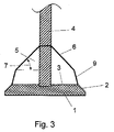
- Fig. 3 shows a closing body according to Fig. 1 But equipped with a hood, which consists of a conical upper part 6 and lower part 9 with different inclination angle of the respective lateral surface to the base.
- the invention protects the closure of bulk solids locks against damage by jammed bulk material. This increases the life of the closure and reduces the frequency of repair stoppages. Thus, the invention increases the economics of the associated reactor and production process. The invention is therefore advantageously industrially applicable.
Landscapes
- Chemical & Material Sciences (AREA)
- Organic Chemistry (AREA)
- Engineering & Computer Science (AREA)
- Chemical Kinetics & Catalysis (AREA)
- Combustion & Propulsion (AREA)
- Oil, Petroleum & Natural Gas (AREA)
- Manufacturing & Machinery (AREA)
- Materials Engineering (AREA)
- Metallurgy (AREA)
- Auxiliary Methods And Devices For Loading And Unloading (AREA)
- Pressure Vessels And Lids Thereof (AREA)
- Devices And Processes Conducted In The Presence Of Fluids And Solid Particles (AREA)
Description
- Die Erfindung betrifft Verschlüsse von Schüttgutschleusen. Durch die Erfindung sollen Störungen des Schließvorganges und Beschädigungen des Verschlusses durch zwischen Verschlusssitz und Schließkörper geratenes Schüttgut vermieden werden. Insbesondere soll mit der Erfindung einem übermäßigen Verschleiß der Dichtungsflächen entgegengewirkt werden.
- Verschlüsse für Schüttgutschleusen umfassen häufig einen Sitz mit kreisförmigem Öffnungsrand und einen scheibenförmigen Schließkörper mit angefaster Schließfläche, wobei der Öffnungsrand und die Grundfläche des Schließkörpers horizontal angeordnet sind. Weiterhin umfassen sie eine Mechanik, die den Schließkörper hält und in vertikaler Richtung bewegen kann, wobei der Schließkörper über eine Stange, Kette oder ein Seil mit der Mechanik verbunden ist. Mittels dieser Mechanik kann der Schließkörper die Öffnung der Schüttgutschleuse verschließen. Dabei wird er mit seiner angefasten Schließfläche gegen den Öffnungsrand gedrückt.
- Schüttgutschleusen mit derartigen Verschlüssen werden häufig zur Beschickung von Festbettdruckvergasungsreaktoren verwendet, in denen ein fester, kohlenstoffhaltiger Brennstoff, wie Kohle oder Koks, unter Verwendung von Sauerstoff und Dampf, zu einem hauptsächlich aus Kohlenmonoxid und Wasserstoff bestehenden Synthesegas vergast wird. Für weitere Verfahrensdetails wird auf das einschlägige Schrifttum verwiesen, vgl. Ullmanns Encyclopedia of Industrial Chemistry, Sixth Edition, Vol. 15, Seite 367 ff.
- Ein Beispiel für einen, dem Gebiet der Erfindung entsprechendem Verschluss, wird in der Anmeldeschrift
US 2014/0191151 A1 gezeigt. - Für die gleiche Anwendung, d. h. zum Schließen von Schüttgutschleusen, wird aber auch eine andere Art von Verschlüssen eingesetzt, für die ein Beispiel in der Offenlegungsschrift
DE 40 41 445 A1 gezeigt ist. - Ein wesentlicher Unterschied zwischen diesen beiden Ausführungsarten besteht in der Form des Schließkörpers. Im ersten Fall hat dieser die Form einer Scheibe, deren obere Kante, zur Bildung einer schrägen Schließfläche, angefast ist.
- Bei der zweiten Ausführungsart ist der Schließkörper kegelförmig. Diese Form gewährleistet, dass die beim Befüllen der Schleuse über den Schließkörper hinweg fallenden Brennstoffklumpen auf der Oberseite des Schließkörpers keinen Halt finden. So wird verhindert, dass sich auf dem Schließkörper Brennstoffklumpen ablagern, die beim Schließen des Verschlusses durch Erschütterungen herabfallen und zwischen die Sitzkante und die Schließfläche des Schließkörpers geraten könnten. Die Ausführung des Schließkörpers als Kegel ist allerdings konstruktiv aufwendiger und kostenintensiver.
- Dagegen ist die Bildung von Brennstoffablagerungen bei einem scheibenförmigen Schließkörper nicht auszuschließen, da dessen Oberseite flach ist. Es besteht daher bei dieser Art des Schließkörpers die Gefahr, dass beim Schließvorgang Brennstoffklumpen zwischen den Verschlusssitz und die Schließfläche geraten und dass es dabei zu Beschädigungen kommt, die ein gasdichtes Abschließen verhindern und so zu Reparaturstillständen der Vergasungsanlage führen,
- Aufgabe der Erfindung ist es eine Vorrichtung vorzuschlagen, mit der ein Verschluss mit einem scheibenförmigen Schließkörper so verändert werden kann, dass die beschriebenen Nachteile vermieden werden.
- Die Aufgabe wird durch eine Vorrichtung gemäß Anspruch 1 gelöst.
- Haube zur Abdeckung der Oberseite eines scheibenförmigen Schließkörpers eines Verschlusses einer Schüttgutschleuse gegen Ablagerungen von Schüttgut, wobei die Haube kegelförmig ist und wobei die Grundfläche der Haube die gleiche Größe hat, wie die Oberseite des Schließkörpers.
- Durch die Abdeckung der flachen Oberseite des scheibenförmigen Schließkörpers mit einer erfindungsgemäßen Haube wird die Ablagerung von Brennstoffklumpen auf dem Schließkörper verhindert. Die Haube deckt die flachen Stellen der Oberseite des Schließkörpers und die auf der Oberseite des Schließkörpers vorhandene Befestigungselemente, Stange oder Kette, mit denen der Schließkörper gehalten und bewegt wird, ab. Es können bereits bestehende Schüttgutschleusen in einfacher Weise mit der erfindungsgemäßen Haube nachgerüstet werden, so dass Dichtigkeitsprobleme, die durch unerwünschte Ablagerungen von Schüttgut auf der flachen Oberfläche des scheibenförmigen Schließkörpers entstehen, reduziert werden.
- Vorteilhaft ist es, dass die Haube aus dünnwandigem Material gefertigt werden kann, da sie lediglich das herabfallende Schüttgut ableiten soll, aber keine mechanischen Kräfte aufnimmt, die sich durch das Einpressen des Schließkörpers in den Sitz des Verschlusses ergeben. Letztere werden allein von dem Schließkörper aufgenommen.
- Eine bevorzugte Ausgestaltung der Erfindung ist dadurch gekennzeichnet, dass sie aus einem oberen kegelförmigen, kegelstumpfförmigen oder halbkugelförmigen Teil und einem unteren zylindrischen oder kegelstumpfförmigen Teil zusammengesetzt ist. Auf diese Weise kann die Form der Haube den jeweiligen Platzverhältnissen angepasst werden, ohne dass Flächen oder Kanten auf der Haubenoberfläche gebildet werden, auf denen es zu Ablagerungen kommen könnte.
- Eine weitere bevorzugte Ausgestaltung der Erfindung ist dadurch gekennzeichnet, dass die Haube so gestaltet ist, dass der zwischen ihrer Kegelmantelfläche und der flachen Oberfläche des Schließkörpers gebildete Winkel größer oder gleich dem Schüttwinkel des in die Schüttgutschleuse gegebenen Schüttguts ist. Auf diese Weise wird erreicht, dass die Neigung der Kegel-, bzw. der Haubenmantelfläche groß genug ist, damit Schüttgutklumpen von ihr abrutschen. Der Schüttgutwinkel muss für das jeweilige Schüttgut gemäß dem Fachmann bekannten Standardmethoden experimentell ermittelt werden.
- Weiterhin umfasst die Erfindung einen Verschluss für eine Schüttgutschleuse, umfassend einen Sitz mit kreisförmigem Öffnungsrand und einen scheibenförmigen Schließkörper mit angefaster Schließfläche, wobei die Oberseite des Schließkörpers mit einer erfindungsgemäßen Haube abgedeckt ist.
- Ferner betrifft die Erfindung auch eine Schüttgutschleuse für einen Festbettdruckvergasungsreaktor, der mit einem erfindungsgemäßen Verschluss ausgestattet ist.
- Schließlich betrifft die Erfindung auch ein Verfahren zur Nachrüstung eines Verschlusses einer Schüttgutschleuse, ausgestattet mit einem scheibenförmigen Schließkörper mit flacher Oberfläche, das dadurch gekennzeichnet ist, dass der scheibenförmige Schließkörper mit flacher Oberfläche mit einer erfindungsgemäßen Haube versehen wird. Auf diese Weise können bereits bestehende Schüttgutschleusen nachgerüstet werden, so dass Dichtigkeitsprobleme, die durch unerwünschte Ablagerungen von Schüttgut auf der flachen Oberfläche des scheibenförmigen Schließkörpers entstehen, reduziert werden.
- Weiterbildungen, Vorteile und Anwendungsmöglichkeiten der Erfindung ergeben sich auch aus der nachfolgenden Beschreibung von nicht beschränkenden Ausführungsbeispielen und den Zeichnungen. Dabei bilden alle beschriebenen und/oder bildlich dargestellten Merkmale für sich oder in beliebiger Kombination die Erfindung, unabhängig von ihrer Zusammenfassung in den Ansprüchen oder deren Rückbeziehung.
- Anhand der Zeichnungen soll die Erfindung im Folgenden erläutert werden. Es zeigen:
- Fig. 1
- einen Längsschnitt eines erfindungsgemäßen Schließkörpers mit kegelförmiger Haube,
- Fig. 2
- einen Längsschnitt eines erfindungsgemäßen Schließkörpers mit einer Haube, die aus einem kegelförmigen oberen und einem zylindrischen unteren Teil besteht,
- Fig. 3
- einen Längsschnitt eines erfindungsgemäßen Schließkörpers mit einer Haube, die aus einem kegelförmigen oberen und unteren Teil mit unterschiedlichem Neigungswinkel der Mantelfläche zur Grundfläche besteht.
-
Fig. 1 zeigt einen scheibenförmigen Schließkörper 1 mit seiner angefasten Schließfläche 2 und seiner flachen Oberseite 3. Der Schließkörper 1 ist mit einer Stange 4 verbunden, mittels der er gehalten und in vertikaler Richtung bewegt wird. Die Haube 5 deckt die flache Oberseite 3 des Schließkörpers 1 vollständig ab, sodass sich dort keine Schüttgutablagerungen bilden können. Die Mantelfläche 6 der Haube 5 bildet mit der flachen Oberseite 3 des Schließkörpers 1 den Winkel 7. -
Fig. 2 zeigt einen Schließkörper gemäßFig. 1 , aber ausgestattet mit einer Haube, die aus einem oberen kegelförmigen Teil 6 und einem unteren zylindrischen Teil 8 besteht. -
Fig. 3 zeigt einen Schließkörper gemäßFig. 1 , aber ausgestattet mit einer Haube, die aus einem kegelförmigen oberen Teil 6 und unteren Teil 9 mit unterschiedlichem Neigungswinkel der jeweiligen Mantelfläche zur Grundfläche besteht. - Die Erfindung schützt den Verschluss von Schüttgutschleusen gegen Beschädigungen durch eingeklemmtes Schüttgut. Dadurch wird die Standzeit des Verschlusses erhöht und die Häufigkeit von Reparaturstillständen verringert. Somit erhöht die Erfindung die Wirtschaftlichkeit des mit ihr verbundene Reaktors und Produktionsverfahrens. Die Erfindung ist daher vorteilhaft gewerblich anwendbar.
-
- 1
- Schließkörper
- 2
- Angefaste Schließfläche
- 3
- Flache Oberseite des Schließkörpers
- 4
- Stange
- 5
- Haube
- 6
- Mantelfläche
- 7
- Winkel
- 8
- Zylindrischer Teil der Haube
- 9
- Unterer, kegelförmiger Teil der Haube
Claims (6)
- Haube zur Abdeckung der Oberseite eines scheibenförmigen Schließkörpers eines Verschlusses einer Schüttgutschleuse gegen Ablagerungen von Schüttgut, wobei die Haube kegelförmig ist und wobei die Grundfläche der Haube die gleiche Größe hat, wie die Oberseite des Schließkörpers.
- Haube gemäß Anspruch 1, dadurch gekennzeichnet, dass sie aus einem oberen kegelförmigen Teil und einem unteren zylindrischen oder kegelstumpfförmigen Teil zusammengesetzt ist.
- Haube gemäß Anspruch 1 oder 2, dadurch gekennzeichnet, dass sie so gestaltet ist, dass der zwischen ihrer Kegelmantelfläche und der flachen Oberfläche des Schließkörpers gebildete Winkel größer oder gleich dem Schüttwinkel des in die Schüttgutschleuse gegebenen Schüttguts ist.
- Verschluss für eine Schüttgutschleuse umfassend einen Sitz mit kreisförmigem Öffnungsrand und einen scheibenförmigen Schließkörper mit angefaster Schließfläche, dadurch gekennzeichnet, dass die Oberseite des Schließkörpers mit einer Haube gemäß den Ansprüchen 1 bis 3 abgedeckt ist.
- Schüttgutschleuse für einen Festbettdruckvergasungsreaktor, umfassend einen Verschluss nach Anspruch 4.
- Verfahren zur Nachrüstung eines Verschlusses einer Schüttgutschleuse, ausgestattet mit einem scheibenförmigen Schließkörper mit flacher Oberfläche, dadurch gekennzeichnet, dass der scheibenförmige Schließkörper mit flacher Oberfläche mit einer Haube gemäß Anspruch 1 bis 3 versehen wird.
Priority Applications (4)
| Application Number | Priority Date | Filing Date | Title |
|---|---|---|---|
| EP16400039.0A EP3290492B1 (de) | 2016-09-06 | 2016-09-06 | Verfahren zur nachrüstung eines verschlusses einer schüttgutschleuse |
| PCT/EP2017/025236 WO2018046137A1 (en) | 2016-09-06 | 2017-08-21 | Hood for the closing body of a closure of a bulk material lock |
| CN201710789549.7A CN107794092A (zh) | 2016-09-06 | 2017-09-05 | 用于散装材料锁的闭合件的封闭体的罩 |
| CN201721127473.3U CN207596798U (zh) | 2016-09-06 | 2017-09-05 | 散装材料锁、用于散装材料锁的闭合件以及用于散装材料锁的闭合件的封闭体的罩 |
Applications Claiming Priority (1)
| Application Number | Priority Date | Filing Date | Title |
|---|---|---|---|
| EP16400039.0A EP3290492B1 (de) | 2016-09-06 | 2016-09-06 | Verfahren zur nachrüstung eines verschlusses einer schüttgutschleuse |
Publications (2)
| Publication Number | Publication Date |
|---|---|
| EP3290492A1 true EP3290492A1 (de) | 2018-03-07 |
| EP3290492B1 EP3290492B1 (de) | 2021-11-10 |
Family
ID=57068025
Family Applications (1)
| Application Number | Title | Priority Date | Filing Date |
|---|---|---|---|
| EP16400039.0A Active EP3290492B1 (de) | 2016-09-06 | 2016-09-06 | Verfahren zur nachrüstung eines verschlusses einer schüttgutschleuse |
Country Status (3)
| Country | Link |
|---|---|
| EP (1) | EP3290492B1 (de) |
| CN (2) | CN107794092A (de) |
| WO (1) | WO2018046137A1 (de) |
Families Citing this family (1)
| Publication number | Priority date | Publication date | Assignee | Title |
|---|---|---|---|---|
| EP3290492B1 (de) * | 2016-09-06 | 2021-11-10 | L'air Liquide, Société Anonyme Pour L'Étude Et L'exploitation Des Procédés Georges Claude | Verfahren zur nachrüstung eines verschlusses einer schüttgutschleuse |
Citations (6)
| Publication number | Priority date | Publication date | Assignee | Title |
|---|---|---|---|---|
| LU45849A1 (de) * | 1964-04-10 | 1964-06-10 | ||
| DE1948440A1 (de) * | 1969-09-25 | 1971-04-15 | Hoesch Ag | Schleuse zum Einbringen von Schuettguetern in gasdicht abgeschlossene Raeume,insbesondere von Legierungselementen in Stahlentgasungsgefaesse |
| DE3838725A1 (de) * | 1987-11-26 | 1989-06-08 | British Steel Plc | Koksofen-beschickungsvorrichtung |
| DE4041445A1 (de) | 1990-12-21 | 1992-07-02 | Schwarze Pumpe Energiewerke Ag | Sicherheitseinrichtung im bekohlungsverschlusssystem von druckgasgeneratoren |
| US20140191151A1 (en) | 2011-07-26 | 2014-07-10 | Sasol Technology (Proprietary) Limited | Solids-handling equipment |
| CN104648855A (zh) * | 2014-11-06 | 2015-05-27 | 扬州伟江机械有限公司 | 密封装料阀 |
Family Cites Families (7)
| Publication number | Priority date | Publication date | Assignee | Title |
|---|---|---|---|---|
| DE95855C (de) * | ||||
| GB1140816A (en) * | 1967-06-09 | 1969-01-22 | Vnii Pk I Metall Maschino | A charging arrangement for a blast furnace |
| DE3718428C1 (en) * | 1987-06-02 | 1988-12-15 | Brabender Technologie Kg | Transport container for bulk material, having an emptying funnel and a conical or plate-shaped shut-off element |
| CN2716672Y (zh) * | 2004-08-14 | 2005-08-10 | 邓运芳 | 鼓风炉顶加料装置底钟 |
| CN201901833U (zh) * | 2010-12-22 | 2011-07-20 | 湘潭公路机械制造有限公司 | 沥青骨料加热的煤气发生装置的气动双钟罩加煤机 |
| DE102014115915A1 (de) * | 2014-10-31 | 2016-05-04 | L'Air Liquide, Société Anonyme pour l'Etude et l'Exploitation des Procédés Georges Claude | Dichtungssystem für einen Behälterverschluss |
| EP3290492B1 (de) * | 2016-09-06 | 2021-11-10 | L'air Liquide, Société Anonyme Pour L'Étude Et L'exploitation Des Procédés Georges Claude | Verfahren zur nachrüstung eines verschlusses einer schüttgutschleuse |
-
2016
- 2016-09-06 EP EP16400039.0A patent/EP3290492B1/de active Active
-
2017
- 2017-08-21 WO PCT/EP2017/025236 patent/WO2018046137A1/en not_active Ceased
- 2017-09-05 CN CN201710789549.7A patent/CN107794092A/zh active Pending
- 2017-09-05 CN CN201721127473.3U patent/CN207596798U/zh active Active
Patent Citations (6)
| Publication number | Priority date | Publication date | Assignee | Title |
|---|---|---|---|---|
| LU45849A1 (de) * | 1964-04-10 | 1964-06-10 | ||
| DE1948440A1 (de) * | 1969-09-25 | 1971-04-15 | Hoesch Ag | Schleuse zum Einbringen von Schuettguetern in gasdicht abgeschlossene Raeume,insbesondere von Legierungselementen in Stahlentgasungsgefaesse |
| DE3838725A1 (de) * | 1987-11-26 | 1989-06-08 | British Steel Plc | Koksofen-beschickungsvorrichtung |
| DE4041445A1 (de) | 1990-12-21 | 1992-07-02 | Schwarze Pumpe Energiewerke Ag | Sicherheitseinrichtung im bekohlungsverschlusssystem von druckgasgeneratoren |
| US20140191151A1 (en) | 2011-07-26 | 2014-07-10 | Sasol Technology (Proprietary) Limited | Solids-handling equipment |
| CN104648855A (zh) * | 2014-11-06 | 2015-05-27 | 扬州伟江机械有限公司 | 密封装料阀 |
Non-Patent Citations (2)
| Title |
|---|
| "Ullmanns Encyclopedia of Industrial Chemistry", vol. 15, pages: 367 FF |
| ANONYMOUS: "Custom Metal Spun Hopper Cone Funnels | SS304 & SS316 | TMS", TMS PRODUCT CATALOGUE, 8 May 2016 (2016-05-08), pages 1 - 3, XP055321639, Retrieved from the Internet <URL:https://www.toledometalspinning.com/products/product-catalog/seamless-hopper-cone-funnels> [retrieved on 20161122] * |
Also Published As
| Publication number | Publication date |
|---|---|
| WO2018046137A1 (en) | 2018-03-15 |
| EP3290492B1 (de) | 2021-11-10 |
| CN207596798U (zh) | 2018-07-10 |
| CN107794092A (zh) | 2018-03-13 |
Similar Documents
| Publication | Publication Date | Title |
|---|---|---|
| AT394053B (de) | Gas-ueberleiteinrichtung fuer einen koksofen | |
| EP2420708B1 (de) | Schaltventil | |
| DE2022907A1 (de) | Schraube | |
| DE2308474A1 (de) | Dosierungsanlage fuer schachtoefen, insbesondere hochoefen | |
| DE2825202A1 (de) | Verschliessvorrichtung | |
| EP3582231B1 (de) | Behälter zur aufnahme von radioaktiven abfallstoffen und behälteraggregat | |
| DE3702892A1 (de) | Verfahren und einrichtung zur behandlung von koernigen feststoffen in einer wirbelschicht | |
| EP3290492B1 (de) | Verfahren zur nachrüstung eines verschlusses einer schüttgutschleuse | |
| DD204855A5 (de) | Einrichtung zum verschliessen einer beschickungsoeffnung fuer druckfeste behaelter | |
| DE3335860A1 (de) | Vorrichtung und arbeitsverfahren zum ausschleusen von materialien aus druckbehaeltern | |
| DE202011102526U1 (de) | Reaktorbehälter | |
| DE102011055516B4 (de) | Bauteil mit einer zylindrischen Innenoberfläche | |
| DE202017103179U1 (de) | Oberteil eines Straßenablaufs | |
| DE1945132C3 (de) | Aufhängevorrichtung für Verteilerglocken von Schachtofen, insbesondere von Hochöfen | |
| DE681741C (de) | Fuellochverschluss | |
| DE2657636B2 (de) | Verschlußvorrichtung für öffnungen eines chargenweise mit rieselfähigem Schüttgut, zähfließenden Aufschwemmungen, Schlämmen o.dgl. beschick- und entleerbaren Behälters | |
| DE3246058A1 (de) | Ventil mit rueckdichtung | |
| DE9106951U1 (de) | Verschlußanordnung für Behälter | |
| DE10030661C2 (de) | Vorrichtung zum Verschließen des Steigrohres eines Verkokungsofens | |
| DE3121587C2 (de) | "Fülleinrichtung für Koksofenkammern" | |
| DE2451757C3 (de) | ||
| DE956960C (de) | Verschlussglocke zum Beschicken von Schachtoefen mit Rohstoffen | |
| DE102015108205A1 (de) | Verschluss | |
| DE20117708U1 (de) | Sicherheitsverschluß insbesondere für Fermentierbehälter für die C02-Produktion für Aquarien oder Ähnliches | |
| DE102010017616A1 (de) | Brückenelement, Brückenlegegerät und Verfahren zur Verriegelung eines Brückenelements |
Legal Events
| Date | Code | Title | Description |
|---|---|---|---|
| PUAI | Public reference made under article 153(3) epc to a published international application that has entered the european phase |
Free format text: ORIGINAL CODE: 0009012 |
|
| STAA | Information on the status of an ep patent application or granted ep patent |
Free format text: STATUS: THE APPLICATION HAS BEEN PUBLISHED |
|
| AK | Designated contracting states |
Kind code of ref document: A1 Designated state(s): AL AT BE BG CH CY CZ DE DK EE ES FI FR GB GR HR HU IE IS IT LI LT LU LV MC MK MT NL NO PL PT RO RS SE SI SK SM TR |
|
| AX | Request for extension of the european patent |
Extension state: BA ME |
|
| STAA | Information on the status of an ep patent application or granted ep patent |
Free format text: STATUS: REQUEST FOR EXAMINATION WAS MADE |
|
| 17P | Request for examination filed |
Effective date: 20180828 |
|
| RBV | Designated contracting states (corrected) |
Designated state(s): AL AT BE BG CH CY CZ DE DK EE ES FI FR GB GR HR HU IE IS IT LI LT LU LV MC MK MT NL NO PL PT RO RS SE SI SK SM TR |
|
| STAA | Information on the status of an ep patent application or granted ep patent |
Free format text: STATUS: EXAMINATION IS IN PROGRESS |
|
| 17Q | First examination report despatched |
Effective date: 20200211 |
|
| GRAP | Despatch of communication of intention to grant a patent |
Free format text: ORIGINAL CODE: EPIDOSNIGR1 |
|
| STAA | Information on the status of an ep patent application or granted ep patent |
Free format text: STATUS: GRANT OF PATENT IS INTENDED |
|
| INTG | Intention to grant announced |
Effective date: 20210824 |
|
| GRAS | Grant fee paid |
Free format text: ORIGINAL CODE: EPIDOSNIGR3 |
|
| GRAA | (expected) grant |
Free format text: ORIGINAL CODE: 0009210 |
|
| STAA | Information on the status of an ep patent application or granted ep patent |
Free format text: STATUS: THE PATENT HAS BEEN GRANTED |
|
| AK | Designated contracting states |
Kind code of ref document: B1 Designated state(s): AL AT BE BG CH CY CZ DE DK EE ES FI FR GB GR HR HU IE IS IT LI LT LU LV MC MK MT NL NO PL PT RO RS SE SI SK SM TR |
|
| REG | Reference to a national code |
Ref country code: GB Ref legal event code: FG4D Free format text: NOT ENGLISH |
|
| REG | Reference to a national code |
Ref country code: AT Ref legal event code: REF Ref document number: 1446095 Country of ref document: AT Kind code of ref document: T Effective date: 20211115 Ref country code: CH Ref legal event code: EP |
|
| REG | Reference to a national code |
Ref country code: DE Ref legal event code: R096 Ref document number: 502016014117 Country of ref document: DE |
|
| REG | Reference to a national code |
Ref country code: IE Ref legal event code: FG4D Free format text: LANGUAGE OF EP DOCUMENT: GERMAN |
|
| REG | Reference to a national code |
Ref country code: LT Ref legal event code: MG9D |
|
| REG | Reference to a national code |
Ref country code: NL Ref legal event code: MP Effective date: 20211110 |
|
| PG25 | Lapsed in a contracting state [announced via postgrant information from national office to epo] |
Ref country code: RS Free format text: LAPSE BECAUSE OF FAILURE TO SUBMIT A TRANSLATION OF THE DESCRIPTION OR TO PAY THE FEE WITHIN THE PRESCRIBED TIME-LIMIT Effective date: 20211110 Ref country code: LT Free format text: LAPSE BECAUSE OF FAILURE TO SUBMIT A TRANSLATION OF THE DESCRIPTION OR TO PAY THE FEE WITHIN THE PRESCRIBED TIME-LIMIT Effective date: 20211110 Ref country code: FI Free format text: LAPSE BECAUSE OF FAILURE TO SUBMIT A TRANSLATION OF THE DESCRIPTION OR TO PAY THE FEE WITHIN THE PRESCRIBED TIME-LIMIT Effective date: 20211110 Ref country code: BG Free format text: LAPSE BECAUSE OF FAILURE TO SUBMIT A TRANSLATION OF THE DESCRIPTION OR TO PAY THE FEE WITHIN THE PRESCRIBED TIME-LIMIT Effective date: 20220210 |
|
| PG25 | Lapsed in a contracting state [announced via postgrant information from national office to epo] |
Ref country code: IS Free format text: LAPSE BECAUSE OF FAILURE TO SUBMIT A TRANSLATION OF THE DESCRIPTION OR TO PAY THE FEE WITHIN THE PRESCRIBED TIME-LIMIT Effective date: 20220310 Ref country code: SE Free format text: LAPSE BECAUSE OF FAILURE TO SUBMIT A TRANSLATION OF THE DESCRIPTION OR TO PAY THE FEE WITHIN THE PRESCRIBED TIME-LIMIT Effective date: 20211110 Ref country code: PT Free format text: LAPSE BECAUSE OF FAILURE TO SUBMIT A TRANSLATION OF THE DESCRIPTION OR TO PAY THE FEE WITHIN THE PRESCRIBED TIME-LIMIT Effective date: 20220310 Ref country code: PL Free format text: LAPSE BECAUSE OF FAILURE TO SUBMIT A TRANSLATION OF THE DESCRIPTION OR TO PAY THE FEE WITHIN THE PRESCRIBED TIME-LIMIT Effective date: 20211110 Ref country code: NO Free format text: LAPSE BECAUSE OF FAILURE TO SUBMIT A TRANSLATION OF THE DESCRIPTION OR TO PAY THE FEE WITHIN THE PRESCRIBED TIME-LIMIT Effective date: 20220210 Ref country code: NL Free format text: LAPSE BECAUSE OF FAILURE TO SUBMIT A TRANSLATION OF THE DESCRIPTION OR TO PAY THE FEE WITHIN THE PRESCRIBED TIME-LIMIT Effective date: 20211110 Ref country code: LV Free format text: LAPSE BECAUSE OF FAILURE TO SUBMIT A TRANSLATION OF THE DESCRIPTION OR TO PAY THE FEE WITHIN THE PRESCRIBED TIME-LIMIT Effective date: 20211110 Ref country code: HR Free format text: LAPSE BECAUSE OF FAILURE TO SUBMIT A TRANSLATION OF THE DESCRIPTION OR TO PAY THE FEE WITHIN THE PRESCRIBED TIME-LIMIT Effective date: 20211110 Ref country code: GR Free format text: LAPSE BECAUSE OF FAILURE TO SUBMIT A TRANSLATION OF THE DESCRIPTION OR TO PAY THE FEE WITHIN THE PRESCRIBED TIME-LIMIT Effective date: 20220211 Ref country code: ES Free format text: LAPSE BECAUSE OF FAILURE TO SUBMIT A TRANSLATION OF THE DESCRIPTION OR TO PAY THE FEE WITHIN THE PRESCRIBED TIME-LIMIT Effective date: 20211110 |
|
| PG25 | Lapsed in a contracting state [announced via postgrant information from national office to epo] |
Ref country code: SM Free format text: LAPSE BECAUSE OF FAILURE TO SUBMIT A TRANSLATION OF THE DESCRIPTION OR TO PAY THE FEE WITHIN THE PRESCRIBED TIME-LIMIT Effective date: 20211110 Ref country code: SK Free format text: LAPSE BECAUSE OF FAILURE TO SUBMIT A TRANSLATION OF THE DESCRIPTION OR TO PAY THE FEE WITHIN THE PRESCRIBED TIME-LIMIT Effective date: 20211110 Ref country code: RO Free format text: LAPSE BECAUSE OF FAILURE TO SUBMIT A TRANSLATION OF THE DESCRIPTION OR TO PAY THE FEE WITHIN THE PRESCRIBED TIME-LIMIT Effective date: 20211110 Ref country code: EE Free format text: LAPSE BECAUSE OF FAILURE TO SUBMIT A TRANSLATION OF THE DESCRIPTION OR TO PAY THE FEE WITHIN THE PRESCRIBED TIME-LIMIT Effective date: 20211110 Ref country code: DK Free format text: LAPSE BECAUSE OF FAILURE TO SUBMIT A TRANSLATION OF THE DESCRIPTION OR TO PAY THE FEE WITHIN THE PRESCRIBED TIME-LIMIT Effective date: 20211110 Ref country code: CZ Free format text: LAPSE BECAUSE OF FAILURE TO SUBMIT A TRANSLATION OF THE DESCRIPTION OR TO PAY THE FEE WITHIN THE PRESCRIBED TIME-LIMIT Effective date: 20211110 |
|
| REG | Reference to a national code |
Ref country code: DE Ref legal event code: R097 Ref document number: 502016014117 Country of ref document: DE |
|
| PLBE | No opposition filed within time limit |
Free format text: ORIGINAL CODE: 0009261 |
|
| STAA | Information on the status of an ep patent application or granted ep patent |
Free format text: STATUS: NO OPPOSITION FILED WITHIN TIME LIMIT |
|
| 26N | No opposition filed |
Effective date: 20220811 |
|
| PG25 | Lapsed in a contracting state [announced via postgrant information from national office to epo] |
Ref country code: AL Free format text: LAPSE BECAUSE OF FAILURE TO SUBMIT A TRANSLATION OF THE DESCRIPTION OR TO PAY THE FEE WITHIN THE PRESCRIBED TIME-LIMIT Effective date: 20211110 |
|
| PG25 | Lapsed in a contracting state [announced via postgrant information from national office to epo] |
Ref country code: SI Free format text: LAPSE BECAUSE OF FAILURE TO SUBMIT A TRANSLATION OF THE DESCRIPTION OR TO PAY THE FEE WITHIN THE PRESCRIBED TIME-LIMIT Effective date: 20211110 |
|
| PG25 | Lapsed in a contracting state [announced via postgrant information from national office to epo] |
Ref country code: MC Free format text: LAPSE BECAUSE OF FAILURE TO SUBMIT A TRANSLATION OF THE DESCRIPTION OR TO PAY THE FEE WITHIN THE PRESCRIBED TIME-LIMIT Effective date: 20211110 |
|
| REG | Reference to a national code |
Ref country code: CH Ref legal event code: PL |
|
| GBPC | Gb: european patent ceased through non-payment of renewal fee |
Effective date: 20220906 |
|
| REG | Reference to a national code |
Ref country code: BE Ref legal event code: MM Effective date: 20220930 |
|
| PG25 | Lapsed in a contracting state [announced via postgrant information from national office to epo] |
Ref country code: IT Free format text: LAPSE BECAUSE OF FAILURE TO SUBMIT A TRANSLATION OF THE DESCRIPTION OR TO PAY THE FEE WITHIN THE PRESCRIBED TIME-LIMIT Effective date: 20211110 |
|
| PG25 | Lapsed in a contracting state [announced via postgrant information from national office to epo] |
Ref country code: LU Free format text: LAPSE BECAUSE OF NON-PAYMENT OF DUE FEES Effective date: 20220906 |
|
| PG25 | Lapsed in a contracting state [announced via postgrant information from national office to epo] |
Ref country code: LI Free format text: LAPSE BECAUSE OF NON-PAYMENT OF DUE FEES Effective date: 20220930 Ref country code: IE Free format text: LAPSE BECAUSE OF NON-PAYMENT OF DUE FEES Effective date: 20220906 Ref country code: FR Free format text: LAPSE BECAUSE OF NON-PAYMENT OF DUE FEES Effective date: 20220930 Ref country code: CH Free format text: LAPSE BECAUSE OF NON-PAYMENT OF DUE FEES Effective date: 20220930 |
|
| PG25 | Lapsed in a contracting state [announced via postgrant information from national office to epo] |
Ref country code: BE Free format text: LAPSE BECAUSE OF NON-PAYMENT OF DUE FEES Effective date: 20220930 |
|
| PG25 | Lapsed in a contracting state [announced via postgrant information from national office to epo] |
Ref country code: GB Free format text: LAPSE BECAUSE OF NON-PAYMENT OF DUE FEES Effective date: 20220906 |
|
| REG | Reference to a national code |
Ref country code: AT Ref legal event code: MM01 Ref document number: 1446095 Country of ref document: AT Kind code of ref document: T Effective date: 20220906 |
|
| PG25 | Lapsed in a contracting state [announced via postgrant information from national office to epo] |
Ref country code: AT Free format text: LAPSE BECAUSE OF NON-PAYMENT OF DUE FEES Effective date: 20220906 |
|
| PG25 | Lapsed in a contracting state [announced via postgrant information from national office to epo] |
Ref country code: HU Free format text: LAPSE BECAUSE OF FAILURE TO SUBMIT A TRANSLATION OF THE DESCRIPTION OR TO PAY THE FEE WITHIN THE PRESCRIBED TIME-LIMIT; INVALID AB INITIO Effective date: 20160906 |
|
| PG25 | Lapsed in a contracting state [announced via postgrant information from national office to epo] |
Ref country code: CY Free format text: LAPSE BECAUSE OF FAILURE TO SUBMIT A TRANSLATION OF THE DESCRIPTION OR TO PAY THE FEE WITHIN THE PRESCRIBED TIME-LIMIT Effective date: 20211110 |
|
| PG25 | Lapsed in a contracting state [announced via postgrant information from national office to epo] |
Ref country code: MK Free format text: LAPSE BECAUSE OF FAILURE TO SUBMIT A TRANSLATION OF THE DESCRIPTION OR TO PAY THE FEE WITHIN THE PRESCRIBED TIME-LIMIT Effective date: 20211110 |
|
| PG25 | Lapsed in a contracting state [announced via postgrant information from national office to epo] |
Ref country code: TR Free format text: LAPSE BECAUSE OF FAILURE TO SUBMIT A TRANSLATION OF THE DESCRIPTION OR TO PAY THE FEE WITHIN THE PRESCRIBED TIME-LIMIT Effective date: 20211110 |
|
| PG25 | Lapsed in a contracting state [announced via postgrant information from national office to epo] |
Ref country code: MT Free format text: LAPSE BECAUSE OF FAILURE TO SUBMIT A TRANSLATION OF THE DESCRIPTION OR TO PAY THE FEE WITHIN THE PRESCRIBED TIME-LIMIT Effective date: 20211110 |
|
| REG | Reference to a national code |
Ref country code: DE Ref legal event code: R081 Ref document number: 502016014117 Country of ref document: DE Owner name: NALWA SPECIAL STEEL (RAIGARH) LTD., IN Free format text: FORMER OWNER: LAIR LIQUIDE, SOCIETE ANONYME POUR L'ETUDE ET L'EXPLOITATION DES PROCEDES GEORGES CLAUDE, PARIS, FR |
|
| PGFP | Annual fee paid to national office [announced via postgrant information from national office to epo] |
Ref country code: DE Payment date: 20250926 Year of fee payment: 10 |