EP3290388A1 - Vehicle with a low gravity center and aerial work platform - Google Patents
Vehicle with a low gravity center and aerial work platform Download PDFInfo
- Publication number
- EP3290388A1 EP3290388A1 EP17188620.3A EP17188620A EP3290388A1 EP 3290388 A1 EP3290388 A1 EP 3290388A1 EP 17188620 A EP17188620 A EP 17188620A EP 3290388 A1 EP3290388 A1 EP 3290388A1
- Authority
- EP
- European Patent Office
- Prior art keywords
- vehicle
- telescopic
- box
- arm
- gravity center
- Prior art date
- Legal status (The legal status is an assumption and is not a legal conclusion. Google has not performed a legal analysis and makes no representation as to the accuracy of the status listed.)
- Withdrawn
Links
Images


Classifications
-
- B—PERFORMING OPERATIONS; TRANSPORTING
- B66—HOISTING; LIFTING; HAULING
- B66F—HOISTING, LIFTING, HAULING OR PUSHING, NOT OTHERWISE PROVIDED FOR, e.g. DEVICES WHICH APPLY A LIFTING OR PUSHING FORCE DIRECTLY TO THE SURFACE OF A LOAD
- B66F17/00—Safety devices, e.g. for limiting or indicating lifting force
- B66F17/006—Safety devices, e.g. for limiting or indicating lifting force for working platforms
-
- B—PERFORMING OPERATIONS; TRANSPORTING
- B66—HOISTING; LIFTING; HAULING
- B66F—HOISTING, LIFTING, HAULING OR PUSHING, NOT OTHERWISE PROVIDED FOR, e.g. DEVICES WHICH APPLY A LIFTING OR PUSHING FORCE DIRECTLY TO THE SURFACE OF A LOAD
- B66F11/00—Lifting devices specially adapted for particular uses not otherwise provided for
- B66F11/04—Lifting devices specially adapted for particular uses not otherwise provided for for movable platforms or cabins, e.g. on vehicles, permitting workmen to place themselves in any desired position for carrying out required operations
-
- A—HUMAN NECESSITIES
- A62—LIFE-SAVING; FIRE-FIGHTING
- A62B—DEVICES, APPARATUS OR METHODS FOR LIFE-SAVING
- A62B35/00—Safety belts or body harnesses; Similar equipment for limiting displacement of the human body, especially in case of sudden changes of motion
- A62B35/0043—Lifelines, lanyards, and anchors therefore
- A62B35/0075—Details of ropes or similar equipment, e.g. between the secured person and the lifeline or anchor
-
- B—PERFORMING OPERATIONS; TRANSPORTING
- B60—VEHICLES IN GENERAL
- B60K—ARRANGEMENT OR MOUNTING OF PROPULSION UNITS OR OF TRANSMISSIONS IN VEHICLES; ARRANGEMENT OR MOUNTING OF PLURAL DIVERSE PRIME-MOVERS IN VEHICLES; AUXILIARY DRIVES FOR VEHICLES; INSTRUMENTATION OR DASHBOARDS FOR VEHICLES; ARRANGEMENTS IN CONNECTION WITH COOLING, AIR INTAKE, GAS EXHAUST OR FUEL SUPPLY OF PROPULSION UNITS IN VEHICLES
- B60K15/00—Arrangement in connection with fuel supply of combustion engines or other fuel consuming energy converters, e.g. fuel cells; Mounting or construction of fuel tanks
- B60K15/03—Fuel tanks
-
- B—PERFORMING OPERATIONS; TRANSPORTING
- B60—VEHICLES IN GENERAL
- B60K—ARRANGEMENT OR MOUNTING OF PROPULSION UNITS OR OF TRANSMISSIONS IN VEHICLES; ARRANGEMENT OR MOUNTING OF PLURAL DIVERSE PRIME-MOVERS IN VEHICLES; AUXILIARY DRIVES FOR VEHICLES; INSTRUMENTATION OR DASHBOARDS FOR VEHICLES; ARRANGEMENTS IN CONNECTION WITH COOLING, AIR INTAKE, GAS EXHAUST OR FUEL SUPPLY OF PROPULSION UNITS IN VEHICLES
- B60K17/00—Arrangement or mounting of transmissions in vehicles
- B60K17/04—Arrangement or mounting of transmissions in vehicles characterised by arrangement, location, or kind of gearing
- B60K17/06—Arrangement or mounting of transmissions in vehicles characterised by arrangement, location, or kind of gearing of change-speed gearing
-
- B—PERFORMING OPERATIONS; TRANSPORTING
- B60—VEHICLES IN GENERAL
- B60K—ARRANGEMENT OR MOUNTING OF PROPULSION UNITS OR OF TRANSMISSIONS IN VEHICLES; ARRANGEMENT OR MOUNTING OF PLURAL DIVERSE PRIME-MOVERS IN VEHICLES; AUXILIARY DRIVES FOR VEHICLES; INSTRUMENTATION OR DASHBOARDS FOR VEHICLES; ARRANGEMENTS IN CONNECTION WITH COOLING, AIR INTAKE, GAS EXHAUST OR FUEL SUPPLY OF PROPULSION UNITS IN VEHICLES
- B60K5/00—Arrangement or mounting of internal-combustion or jet-propulsion units
- B60K5/12—Arrangement of engine supports
-
- B—PERFORMING OPERATIONS; TRANSPORTING
- B66—HOISTING; LIFTING; HAULING
- B66C—CRANES; LOAD-ENGAGING ELEMENTS OR DEVICES FOR CRANES, CAPSTANS, WINCHES, OR TACKLES
- B66C23/00—Cranes comprising essentially a beam, boom, or triangular structure acting as a cantilever and mounted for translatory of swinging movements in vertical or horizontal planes or a combination of such movements, e.g. jib-cranes, derricks, tower cranes
- B66C23/62—Constructional features or details
- B66C23/64—Jibs
- B66C23/70—Jibs constructed of sections adapted to be assembled to form jibs or various lengths
- B66C23/701—Jibs constructed of sections adapted to be assembled to form jibs or various lengths telescopic
- B66C23/705—Jibs constructed of sections adapted to be assembled to form jibs or various lengths telescopic telescoped by hydraulic jacks
-
- B—PERFORMING OPERATIONS; TRANSPORTING
- B66—HOISTING; LIFTING; HAULING
- B66F—HOISTING, LIFTING, HAULING OR PUSHING, NOT OTHERWISE PROVIDED FOR, e.g. DEVICES WHICH APPLY A LIFTING OR PUSHING FORCE DIRECTLY TO THE SURFACE OF A LOAD
- B66F11/00—Lifting devices specially adapted for particular uses not otherwise provided for
- B66F11/04—Lifting devices specially adapted for particular uses not otherwise provided for for movable platforms or cabins, e.g. on vehicles, permitting workmen to place themselves in any desired position for carrying out required operations
- B66F11/044—Working platforms suspended from booms
- B66F11/046—Working platforms suspended from booms of the telescoping type
-
- B—PERFORMING OPERATIONS; TRANSPORTING
- B66—HOISTING; LIFTING; HAULING
- B66F—HOISTING, LIFTING, HAULING OR PUSHING, NOT OTHERWISE PROVIDED FOR, e.g. DEVICES WHICH APPLY A LIFTING OR PUSHING FORCE DIRECTLY TO THE SURFACE OF A LOAD
- B66F7/00—Lifting frames, e.g. for lifting vehicles; Platform lifts
- B66F7/02—Lifting frames, e.g. for lifting vehicles; Platform lifts with platforms suspended from ropes, cables, or chains or screws and movable along pillars
- B66F7/04—Lifting frames, e.g. for lifting vehicles; Platform lifts with platforms suspended from ropes, cables, or chains or screws and movable along pillars hydraulically or pneumatically operated
-
- B—PERFORMING OPERATIONS; TRANSPORTING
- B66—HOISTING; LIFTING; HAULING
- B66F—HOISTING, LIFTING, HAULING OR PUSHING, NOT OTHERWISE PROVIDED FOR, e.g. DEVICES WHICH APPLY A LIFTING OR PUSHING FORCE DIRECTLY TO THE SURFACE OF A LOAD
- B66F7/00—Lifting frames, e.g. for lifting vehicles; Platform lifts
- B66F7/22—Lifting frames, e.g. for lifting vehicles; Platform lifts with tiltable platforms
-
- B—PERFORMING OPERATIONS; TRANSPORTING
- B66—HOISTING; LIFTING; HAULING
- B66F—HOISTING, LIFTING, HAULING OR PUSHING, NOT OTHERWISE PROVIDED FOR, e.g. DEVICES WHICH APPLY A LIFTING OR PUSHING FORCE DIRECTLY TO THE SURFACE OF A LOAD
- B66F9/00—Devices for lifting or lowering bulky or heavy goods for loading or unloading purposes
- B66F9/06—Devices for lifting or lowering bulky or heavy goods for loading or unloading purposes movable, with their loads, on wheels or the like, e.g. fork-lift trucks
- B66F9/075—Constructional features or details
- B66F9/07513—Details concerning the chassis
-
- B—PERFORMING OPERATIONS; TRANSPORTING
- B66—HOISTING; LIFTING; HAULING
- B66F—HOISTING, LIFTING, HAULING OR PUSHING, NOT OTHERWISE PROVIDED FOR, e.g. DEVICES WHICH APPLY A LIFTING OR PUSHING FORCE DIRECTLY TO THE SURFACE OF A LOAD
- B66F13/00—Common constructional features or accessories
-
- B—PERFORMING OPERATIONS; TRANSPORTING
- B66—HOISTING; LIFTING; HAULING
- B66F—HOISTING, LIFTING, HAULING OR PUSHING, NOT OTHERWISE PROVIDED FOR, e.g. DEVICES WHICH APPLY A LIFTING OR PUSHING FORCE DIRECTLY TO THE SURFACE OF A LOAD
- B66F7/00—Lifting frames, e.g. for lifting vehicles; Platform lifts
- B66F7/28—Constructional details, e.g. end stops, pivoting supporting members, sliding runners adjustable to load dimensions
Definitions
- the present invention relates to field of engineering mechanics and more particularly, relates to an engineering work vehicle, and most particularly, relates to a vehicle with a low gravity center and aerial work platform.
- Aerial work platform is an advanced aerial working mechanical device, and is capable of significantly improving efficiency, safety, and comfort of operators at height, and is also capable of reducing labor. Accordingly, it is widely employed in developed countries. This aerial work platform is also extensively used in China in many fields such as urban street lamp maintenance, tree trimming or the like. With rapid development of Chinese economy, aerial work platform is increasingly required in many situations such as engineering construction, industry installation, equipment repair, workshop maintenance, ship manufacture, electric power, municipal construction, airport, communications, city park, and transportation.
- an engine, fuel tank and hydraulic tank are all laterally mounted on a turret.
- a relatively high gravity center is resulted for the vehicle. This restricts off-road ability and grade-ability of the aerial work platform. In addition, this also restricts horizontal reach of the aerial work platform. In other words, the horizontal reach of an operation platform is limited.
- the aerial work platform often runs in a complicated environment and accordingly, it is required to make some improvement upon structure and/or installation manner of relevant components of the vehicle. Therefore, there is need for providing an aerial work platform to overcome drawbacks of above prior art aerial work platform.
- An object of the present invention is to address above problems and provide a vehicle with a low gravity center and aerial work platform.
- power system, fuel tank and hydraulic tank are mounted at a side of a vehicle frame of a vehicle to lower gravity center of the vehicle and entire aerial work platform, enhance off-road capability and grade-ability of the aerial work platform, and increase horizontal reach of the aerial work platform, thereby enlarging working range of the aerial work platform.
- the present invention proposes a vehicle with a low gravity center for an aerial work platform.
- the vehicle includes a vehicle frame, a power system, a fuel tank, and a hydraulic tank all of which are mounted at a side of the frame.
- the power system, fuel tank, and hydraulic tank are all disposed at a side of the vehicle frame along a length direction.
- first box and a second box are installed on two sides of the frame along the length direction of the frame respectively.
- the power system is contained in the first box, whereas the fuel tank and hydraulic tank are contained in the second box.
- the power system includes an engine located in the first box and secured onto the vehicle frame through a bracket.
- a damping device is disposed at a location where the engine and bracket are connected together.
- the fuel tank, hydraulic tank, and second box are integrally formed.
- control box is disposed on the second box and is foldable into and out of the second box.
- the power system further includes a cooling component, a fuel delivery component, and an intake-exhaust component.
- the present invention further provides an aerial work platform including a vehicle with lower gravity center as mentioned above, a telescopic transmission component pivotablly mounted on the vehicle, and an operation platform disposed on a distal end of the telescopic transmission component.
- a turret is disposed on the vehicle frame of the vehicle.
- One end, away from the operation platform, of the telescopic transmission component, is pivotablly connected with the turret through a supporting arm.
- the operation platform is connected with the telescopic transmission component via a telescopic connection component.
- a supporting member is disposed between the supporting arm and telescopic transmission component, and similarly, another supporting member is placed between the telescopic transmission component and telescopic connection component.
- the gravity center of the aerial work platform is able to be lowered by 0.4m-0.6m, thus strongly improving off-road performance and grade-ability of the entire platform. Accordingly, the aerial work platform is able to run under various complex environments. In addition, the horizontal reach of the aerial work platform is also increased, and work range of the same is also extended.
- the power system is disposed in the first box, while the fuel tank and hydraulic tank is disposed in the second box.
- the first and second boxes are able to protect relevant components therein effectively, avoiding collision of these components with external objects and thereby avoiding damages to the same. This also decreases dust and aging of the components and therefore, further reduces cost of maintenance and repair, and extends life of the components.
- a damping device is provided between the engine and bracket, damage to the engine due to vehicle shake during running of the aerial work platform is effectively prevented, thus further reducing cost of maintenance and repair, and extending life of the components.
- the fuel tank, hydraulic tank, and second box are integrally formed, manufacture and installation is convenient, the entire construction is simple and compact, and appearance is good.
- the inventive aerial work platform has better off-road performance and grade-ability, can work in complicated environment, and owns a longer horizontal reach and larger working range. Moreover, maintenance and repair cost is decreased, lifetime is extended, integrity is higher and appearance looks better.
- FIGS 1-16 show a typical embodiment of an aerial work platform of the present invention.
- the aerial work platform incudes a vehicle 1, a telescopic transmission component 2 pivotablly installed on the vehicle 1, and an operation platform 3 connected to a distal end of the telescopic transmission component 2 via a telescopic connection component 5.
- the vehicle 1 includes a vehicle frame 102, a driving system, a fuel tank 121, and a hydraulic tank 122.
- the driving system includes a power system, a transmission mechanism, a control system, a driving mechanism, and a wheel assembly.
- the power system, fuel tank 121 and hydraulic tank 122 are all installed at a side of the frame 102 along a length direction of the frame 102.
- a turret 101 is provided on an upper end of the frame 102 of the vehicle 1.
- One end, away from the operation platform 3, of the telescopic transmission component 2, is pivotablly connected with the turret 101 through a supporting arm 4.
- the operation platform 3 is coupled with the telescopic transmission component 2 by means of a telescopic connection component 5.
- a supporting member (for example a cylinder with kinds of functions) is disposed between the supporting arm 4 and telescopic transmission component 2, and similarly, another supporting member is placed between the telescopic transmission component 2 and telescopic connection component 5.
- FIG. 1-5 Fixed to two lateral sides of the vehicle frame 102 respectively along its length direction are a first box 11 and a second box 12.
- the power system is contained in the first box 11, whereas the fuel tank 121 and hydraulic tank 122 are located in the second box 12.
- the power system includes an engine 112, a cooling component, a fuel delivery component, and an intake-exhaust component.
- the engine 112 is positioned in the first box 11 and is mounted onto the frame 102 by a bracket 114.
- a damping device (not shown) is disposed at a location where the engine 112 and bracket 114 are connected together.
- the fuel tank 121, hydraulic tank 122, and second box 12 are integrally formed.
- a control box 123 is disposed on the second box 12 and is foldable into and out of the second box 12.
- the control box 123 is electrically connected with the control system.
- a turning opening is defined at a side of the second box 12 for turning the control box 123 into and out of the second box 12.
- An upper edge (See orientation of the control box in figure 3 of control box 123) is hinged to an upper edge of the turning opening.
- the height of the control box 123 relative to the ground is such designed that, when the control box 123 is rotated out of the second box 12 through the turning opening, an operator standing on the ground will be able to comfortably get access to the control box 123.
- relevant control devices may be provided on the operation platform 3 and be coupled with the control system electrically.
- the gravity center of the aerial work platform is able to be lowered by 0.4m-0.6m, thus strongly improving off-road performance and grade-ability of the entire platform. Accordingly, the aerial work platform is able to run under various complex environments. In addition, the horizontal reach of the aerial work platform is also increased, and work range of the same is also extended.
- the telescopic connection component 5 includes an outer arm 51, an inner arm 52 slidably disposed inside the outer arm 51 and capable of being moved out from one end of the outer arm 51, and a forearm telescopic cylinder 53 disposed between the outer arm 51 and inner arm 52.
- the forearm telescopic cylinder 53 includes a cylinder body (not shown) and a piston rod (not shown) slidably disposed into the cylinder body.
- the cylinder body is secured onto an outer wall of the outer arm 51, and an extension end of the piston rod is secured onto an outer wall of the inner arm 52.
- a first levelling cylinder 55 is disposed between the telescopic transmission component 2 and telescopic connection component 5.
- a forearm head 54 is hinged to one end, which is connected to the telescopic transmission component 2, of the telescopic connection component 5.
- One end of the first levelling cylinder 55 is hinged to the telescopic transmission component 2, while the other end thereof is hinged to the forearm head 54.
- the telescopic connection component 5 further includes a forearm luffing cylinder 57 one end of which is hinged to the forearm head 54, while the other end thereof is hinged to the outer wall of the outer arm 51.
- the forearm head 54, outer arm 51 and telescopic transmission component 2 are hinged together by a pin 512.
- the first levelling cylinder 55, forearm head 54, forearm luffing cylinder 57 and outer arm 51 constitute a four-bar linkage.
- the first levelling cylinder 55 may operate electrically or hydraulically.
- an angle sensor (not shown) matched with the first levelling cylinder 55 is installed on the pin 512 which hinges the forearm head 54, outer arm 51 and telescopic transmission component 2 together.
- a hydraulic levelling device matched with the first levelling cylinder 55 is disposed on the telescopic transmission component 2.
- the first levelling cylinder 55 works in electrical levelling manner.
- the forearm head 54 may be leveled by pushing and pulling motion of the first levelling cylinder 55 upon the head 54.
- an angle sensor installed on the forearm head 54 sets an angle of the head 54 as zero.
- angle signal of the forearm head 54 will be sent to a corresponding controller through the angle sensor.
- the controller After receiving the signal, the controller will generate a corresponding command to cause telescopic motion of the first levelling cylinder 55, thereby realizing levelling of the forearm head 54.
- the forearm head 54 is controlled to be oriented at its predefined zero angle.
- up and down luffing of the telescopic connection component 5 may also be realized by telescopic movement of the forearm luffing cylinder 57.
- a third levelling cylinder 58 is disposed between the telescopic connection component 5 and operation platform 3.
- One end of the third levelling cylinder 58 is hinged to the inner arm 52, whereas the other end thereof is hinged to a rotary cylinder 33 secured onto the operation platform 3.
- a second levelling cylinder 56 is positioned between the forearm head 54 and telescopic connection component 5.
- One end of the second levelling cylinder 56 is hinged to the forearm head 54, while the other end thereof is hinged to the outer wall of the outer arm 51.
- a cavity of the second levelling cylinder 56 communicates with a cavity of the third levelling cylinder 58 by means of an oil tube.
- the second levelling cylinder 56 and third levelling cylinder 58 avoids tilting of the operation platform 3 during luffing of the telescopic connection component 5. In other words, the operation platform 3 is always maintained at a horizontal location during luffing of the telescopic connection component 5. Accordingly, the second levelling cylinder 56 and third levelling cylinder 58 have a second level of levelling function (the first levelling cylinder 55 and associated device realize a first level of levelling function). As the cavity of the second levelling cylinder 56 communicates with that of the third levelling cylinder 58 by an oil tube, levelling may be achieved by adjusting telescopic motion of the second and third levelling cylinders 56 and 58. The detailed levelling processing is described below.
- a telescopic rod of the forearm luffing cylinder 57 comes out and at the same time, a telescopic rod of the second levelling cylinder 56 also comes out.
- hydraulic medium inside a rod chamber of the second levelling cylinder 56 flows under pressure into a rod chamber of the third levelling cylinder 58.
- a telescopic rod of the third levelling cylinder 58 retracts, and hydraulic medium contained inside the non-rod chamber of the third levelling cylinder 58 flows into a non-rod chamber of the second levelling cylinder 56 through an oil tube so as to realize levelling by balancing pressure inside relevant chambers of the second and third levelling cylinders 56 and 58.
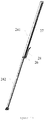
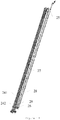
- the telescopic transmission component 2 includes a base arm 21, a second arm 22, a third arm, a telescopic cylinder 24, a rope-expanding chain 27, and a rope-retracting chain 28.
- the second arm 22 is inserted into the base arm 21 and is able to move out of the base arm 21 (See an upper portion of figure 11 ).
- the third arm 23 is inserted into the second arm 22 and is capable of coming out of an extension end of the same (See an upper portion of figure 11 ).
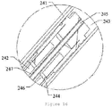
- the telescopic cylinder 24 includes a cylinder barrel 241 secured onto the second arm 22 and a telescopic rod 242 inserted into the barrel 241.
- the telescopic rod 242 has a hollow arrangement 247 communicating with a cavity of the cylinder barrel 241.
- An oil guiding tube 245 is provided into the hollow arrangement 247 of the telescopic rod 242, and the extension end of the telescopic rod 242 is secured onto the base arm 21 (See a lower portion of figure 13 ) .
- an end surface of the extension end of the telescopic rod 242 is fixed to the base arm 21 through a mounting plate 8.
- connection portion is provided on the cylinder barrel 241 at a location adjacent to the extension end of the telescopic rod 242 for securing the barrel 241 to the second arm 22.
- the connection portion may in the form of an axle hole. That is, the cylinder barrel 241 may be mounted on the second arm 22 by inserting a pin into said axle hole.
- the connection portion of the barrel 241 may also be designed to locate at other positions of the barrel 241, for example at a middle position.
- a first sprocket wheel 25 is provided on the telescopic cylinder 24, a second sprocket wheel 26 is provided on the second arm 22, and the second sprocket wheel 26 is closer to the extension end of the cylinder barrel 241 than does the first sprocket wheel 25.
- One end of the rope-expanding chain 27 is attached onto the base arm 21, while the other end thereof runs around the first sprocket wheel 25 and then is attached onto the third arm 23. In other words, the two ends of the rope-expanding chain 27 are both located below the first sprocket wheel 25 (See orientation of figures).
- One end of the rope-retracting chain 28 is attached onto the third arm 23, while the other end thereof runs around the second sprocket wheel 26 and then is attached onto the base arm 21.
- the two ends of the rope-retracting chain 28 are both located above the second sprocket wheel 26(See orientation of figures).
- the first sprocket wheel 25 is located on a cylinder head, which cylinder head is located at one end away from an extension end, of the telescopic cylinder 24.
- the second sprocket wheel 26 is located on the second arm 22 at a location adjacent to the extension end of the telescopic rod 242.
- the first and second sprocket wheels 25 and 26 are capable of being positioned above and below the cylinder barrel 241(See orientation of figures). This ensures stable movement of the cylinder barrel 241 and accordingly, it also ensures stable rotation and telescopic motion of relevant components.
- the first and second sprocket wheels 25 and 26 may also be positioned at other suitable locations.
- the first sprocket wheel 25 may be located at a middle area of the cylinder barrel 241
- the second sprocket wheel 26 may be placed on the second arm 22 at a location close to a middle portion of the cylinder barrel 241.
- an inner cavity of the cylinder barrel 241 of the telescopic cylinder 24 is separated to form a rod chamber 244 and a non-rod chamber 243.
- partial space of the inner cavity of the barrel 241 overlaps the telescopic rod 242 and thus forms the rod chamber 244.
- Partial space of the inner cavity of the barrel 241 doesn't overlap the rod 242 and locates at a upper right side (See figure 16 ) of a distal end of the telescopic rod, and accordingly, forms the non-rod chamber 243.
- the hollow arrangement 247 of the telescopic rod 242 communicates with the rod chamber 244 via a connection path 246.
- the hollow arrangement 247 of the rod 242 together with the oil guiding tube 245 inside the arrangement 247 is communicated with an external oil tube.
- one end of the rope-retracting chain 28 is attached onto the third arm 23 by means of a chain connection member 29, similarly, one end of the rope-expanding chain 27 is also attached onto the third arm 23 by means of the chain connection member 29, and the two ends are located at two sides of the chain connection member 29.
- motions of the rope-expanding chain 27, rope-retracting chain 28 and third arm 23 are coordinated among each other.
- the rope-expanding chain 27 and rope-retracting chain 28 may be connected to the third arm 23 with different connective members.
- a chain detection device is provided on the rope-expanding chain 27 for real time detecting status of related chain. When a chain is broken or exceeds a predefined loose value, the chain detection device will generate alert signals to guarantee safety of the telescopic transmission component 2, and further guarantee safety of operators and other staff.
- the chain detection device may be disposed on the rope-expanding chain 27 at one end thereof where the chain 27 is connected to the base arm 21.
- all of the base arm 21, second arm 22 and third arm 23 are of hollow arrangement. It is noted that these arms are by no means limited to this hollow arrangement, and in fact they may be of other constructions.
- these hollow arrangements of the base arm 21, second arm 22 and third arm 23 form a telescopic cavity into which the telescopic cylinder 24, first sprocket wheel 25, second sprocket wheel 26, rope-expanding chain 27 and rope-retracting chain 28 are received, thus leading to a compact structure for the telescopic transmission component 2, and further reducing wear and aging of the components, thereby extending lifetime.
- This also reduces repair and maintenance frequency and makes it more convenient to repair and maintain the same, thus decreasing related costs.
- these components are not exposed outside and accordingly, risk of operators being injured due to unintentional collision with the components is also reduced.
- the cylinder barrel 241 will move upwardly together with the second arm 22 such that the second arm 22 will move out of the base arm 21.
- the third arm 23 is pulled to move out of an upper end of the second arm 22.
- the second arm 22 and third arm 23 will continue to move toward the upper end until desired travel distance or maximum predefined distance is reached.
- the first sprocket wheel functions as a movable pulley, and in this situation, displacement of the third arm 23 relative to the base arm 21 is two times as long as a travel distance of the cylinder barrel 241 (the distance of the second arm 22 with respect to the base arm 21). In this case, telescopic distance is certainly extended.
- the barrel 241 When oil enters the rod chamber 244 of the cylinder barrel 241 through the hollow arrangement 247 of the telescopic rod 242, the barrel 241 will drive the second arm 22 to move together downwardly such that the second arm 22 will retract from the upper end of the base arm 21.
- the third arm 23 will retract into the second arm 22 when driven by the rope-retracting chain 28 and second sprocket wheel 26.
- the second arm 22 and third arm 23 With continuous oil injection into the telescopic rod 242, the second arm 22 and third arm 23 will continuously retract towards a low end until a desired retracting location or complete retracting location is reached.
- the second sprocket wheel 26 works as a movable pulley such that the displacement of the third arm 23 relative to the base arm 21 is two times as long as the travel distance of the cylinder barrel 241 (that is, the distance of the second arm 22 relative to the base arm 21).
- the third arm 23 is hinged to the operation platform 3 by said telescopic connection component 5.
- the third arm 23 is hinged to the outer arm 51 of the telescopic connection component 5, and the inner arm 52 of the component 5 is connected with the operation platform 3.
- the telescopic connection component 5 helps the operation platform 3 move further along a horizontal direction.
- the base arm 21 is hinged to the vehicle 1 by the supporting arm 4 which is movably connected with relevant component of the vehicle 1.
- a luffing cylinder 6 is disposed between the base arm 21 and supporting arm 4.
- the second and third arms 22, 23 are controlled to extend of the telescopic transmission component 2.
- the operation platform 3 coupled with the telescopic transmission component 2 will also be extended when driven by the third arm 23.
- relevant cylinder 6, supporting arm 4 and telescopic connection component 5 are also controlled to adjust angle or location of relevant arms until the operation platform 3 moves to a predefined working location or a maximum extension distance is reached.
- the second and third arms 22, 23 of the telescopic transmission component 2 are controlled to retract.
- the operation platform 3 coupled with the telescopic transmission component 2 will also be retracted when driven by the third arm 23.
- relevant cylinder 6, supporting arm 4 and telescopic connection component 5 are also controlled to adjust angle or location of relevant arms until the operation platform 3 moves to a predefined working location or returns to its original location without extension.
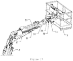
- figure 17 illustrates another example of an aerial work platform of the invention.
- This example is different from the above example in that: a luffing cylinder 57 in place of relevant first level of levelling components of the above example and serving as a supporting member is disposed between the telescopic transmission component 2 and telescopic connection component 5; and the third levelling cylinder 58 works in an electrical levelling manner other than hydraulic levelling manner as described in above example, that is, an angle sensor 59 cooperating with the third levelling cylinder 58 is provided on the rotary cylinder 33.
- up and down luffing action of the telescopic connection component 5 is realized by telescopic motion of the luffing cylinder 57 located between the telescopic transmission component 2 and telescopic connection component 5.
- Levelling of the operation platform is conducted by telescopic motion of the third levelling cylinder 58, thus ensuring all time horizontal orientation of the platform.
- an angle sensor 59 installed on the rotary cylinder 33 sets a location of the operation platform 3 as zero.
- this angle sensor 59 will transmits electrical signals to a corresponding controller which when receives the signals, will send control command to cause telescopic motion of the third levelling cylinder 58, hence realizing levelling of the operation platform. in other words, it is maintained that the operation platform is always in its zero location.
- the inventive aerial work platform has better off-road performance and grade-ability, can work in complicated environment, and owns a longer horizontal reach and larger working range (it is extended by at least 1.2 meters than a prior art aerial work platform). Moreover, maintenance and repair cost is decreased, lifetime is extended, integrity is higher and appearance looks better.
Applications Claiming Priority (1)
| Application Number | Priority Date | Filing Date | Title |
|---|---|---|---|
| CN201610778675.8A CN106430018B (zh) | 2016-08-31 | 2016-08-31 | 具有低重心的车体及高空作业平台 |
Publications (1)
| Publication Number | Publication Date |
|---|---|
| EP3290388A1 true EP3290388A1 (en) | 2018-03-07 |
Family
ID=58091024
Family Applications (1)
| Application Number | Title | Priority Date | Filing Date |
|---|---|---|---|
| EP17188620.3A Withdrawn EP3290388A1 (en) | 2016-08-31 | 2017-08-30 | Vehicle with a low gravity center and aerial work platform |
Country Status (8)
| Country | Link |
|---|---|
| US (1) | US10315902B2 (ja) |
| EP (1) | EP3290388A1 (ja) |
| JP (1) | JP6495975B2 (ja) |
| KR (1) | KR20180025168A (ja) |
| CN (1) | CN106430018B (ja) |
| AU (1) | AU2017204042B2 (ja) |
| CA (1) | CA2976477C (ja) |
| SG (1) | SG10201705739UA (ja) |
Cited By (1)
| Publication number | Priority date | Publication date | Assignee | Title |
|---|---|---|---|---|
| WO2020056069A1 (en) * | 2018-09-12 | 2020-03-19 | Jlg Industries, Inc. | Below grade access platform |
Families Citing this family (3)
| Publication number | Priority date | Publication date | Assignee | Title |
|---|---|---|---|---|
| US10611618B2 (en) * | 2015-03-27 | 2020-04-07 | Chang Zhou Current Supply Company Of Jiangsu Electric Power Company | Amplitude limiting system of insulated aerial work platform |
| US20210219489A1 (en) * | 2018-06-19 | 2021-07-22 | Kubota Corporation | Work Machine |
| CN109368513A (zh) * | 2018-12-14 | 2019-02-22 | 山河智能装备股份有限公司 | 隧道模板转运车 |
Citations (5)
| Publication number | Priority date | Publication date | Assignee | Title |
|---|---|---|---|---|
| US3856108A (en) * | 1973-05-25 | 1974-12-24 | Fulton Industries | Three wheel aerial platform apparatus |
| US3998288A (en) * | 1974-05-07 | 1976-12-21 | Shikoku Kenki Kabushiki Kaisha | Wheeled vehicle for conveying loads |
| JP2006225055A (ja) * | 2005-02-15 | 2006-08-31 | Seirei Ind Co Ltd | 高所作業車 |
| CN201473280U (zh) * | 2009-09-23 | 2010-05-19 | 湖南山河智能机械股份有限公司 | 回转式伸缩臂叉装车 |
| US20150284219A1 (en) * | 2014-04-07 | 2015-10-08 | Miller Industries Towing Equipment Inc. | Vehicle wrecker with improved controls |
Family Cites Families (22)
| Publication number | Priority date | Publication date | Assignee | Title |
|---|---|---|---|---|
| DE3334059A1 (de) * | 1983-09-21 | 1985-04-18 | Peter 5000 Köln Zeuner | Vorrichtung zur reinigung und pflege von flugzeugen |
| US4775029A (en) * | 1987-10-08 | 1988-10-04 | Jlg Industries, Inc. | Collapsible tower boom lift |
| JPH0650480Y2 (ja) * | 1989-06-30 | 1994-12-21 | 株式会社アイチコーポレーション | リフト作業車の遠隔操作装置 |
| US5021917A (en) * | 1990-01-29 | 1991-06-04 | Kidde Industries, Inc. | Control panel power enabling and disabling system for aerial work platforms |
| JPH0742077B2 (ja) * | 1990-02-09 | 1995-05-10 | 極東開発工業株式会社 | 高所作業車の作業範囲規制装置 |
| DE9302376U1 (ja) * | 1993-02-18 | 1993-06-24 | Ec Engineering + Consulting Spezialmaschinen Gmbh, 7900 Ulm, De | |
| JPH09104598A (ja) * | 1995-10-06 | 1997-04-22 | Nippon Yusoki Co Ltd | 荷役車両の荷役操作装置 |
| US5743149A (en) * | 1996-02-26 | 1998-04-28 | Skyjack Equipment Inc. | Articulated telescopic boom having slide-through knuckle |
| JP2000095499A (ja) * | 1998-09-24 | 2000-04-04 | Aichi Corp | 電気駆動作業装置におけるバッテリ容量算出システム |
| JP2000247598A (ja) * | 1999-02-26 | 2000-09-12 | Komatsu Forklift Co Ltd | フォークリフトトラックにおける作業機用操作レバーの取付け構造 |
| JP2000344134A (ja) * | 1999-06-09 | 2000-12-12 | Komatsu Ltd | ホイール式多目的作業車 |
| CN1915783A (zh) * | 2001-09-28 | 2007-02-21 | 神钢建设机械株式会社 | 自走式作业机械 |
| JP2005262978A (ja) * | 2004-03-17 | 2005-09-29 | Hitachi Constr Mach Co Ltd | 作業機械およびその製造方法 |
| JP2006225054A (ja) * | 2005-02-15 | 2006-08-31 | Seirei Ind Co Ltd | 高所作業車 |
| CN201193191Y (zh) * | 2008-03-13 | 2009-02-11 | 广东力士通机械股份有限公司 | 轮胎起重机 |
| IT1400017B1 (it) * | 2010-04-20 | 2013-05-09 | Cte S P A | Piattaforma aerea di lavoro telescopica |
| CN202729731U (zh) * | 2012-05-30 | 2013-02-13 | 美通(南通)重工有限公司 | 剪叉车底盘电控装置 |
| US9139409B2 (en) * | 2013-03-12 | 2015-09-22 | Oshkosh Corporation | Weighted boom assembly |
| CN203728454U (zh) * | 2014-01-22 | 2014-07-23 | 宝鸡南车时代工程机械有限公司 | 用于铁路施工的起重轨道车 |
| CN204356033U (zh) * | 2014-04-16 | 2015-05-27 | 河南江河起重机有限公司 | 一种高空作业平台底盘 |
| CN204529249U (zh) * | 2015-04-03 | 2015-08-05 | 上海智远弘业机器人有限公司 | 一种低高度全向移动升降平台车 |
| CN206634990U (zh) * | 2016-08-31 | 2017-11-14 | 浙江鼎力机械股份有限公司 | 具有低重心的车体及高空作业平台 |
-
2016
- 2016-08-31 CN CN201610778675.8A patent/CN106430018B/zh active Active
-
2017
- 2017-06-15 AU AU2017204042A patent/AU2017204042B2/en active Active
- 2017-07-12 JP JP2017135841A patent/JP6495975B2/ja active Active
- 2017-07-12 US US15/647,591 patent/US10315902B2/en active Active
- 2017-07-12 SG SG10201705739UA patent/SG10201705739UA/en unknown
- 2017-07-17 KR KR1020170090335A patent/KR20180025168A/ko not_active Application Discontinuation
- 2017-08-15 CA CA2976477A patent/CA2976477C/en active Active
- 2017-08-30 EP EP17188620.3A patent/EP3290388A1/en not_active Withdrawn
Patent Citations (5)
| Publication number | Priority date | Publication date | Assignee | Title |
|---|---|---|---|---|
| US3856108A (en) * | 1973-05-25 | 1974-12-24 | Fulton Industries | Three wheel aerial platform apparatus |
| US3998288A (en) * | 1974-05-07 | 1976-12-21 | Shikoku Kenki Kabushiki Kaisha | Wheeled vehicle for conveying loads |
| JP2006225055A (ja) * | 2005-02-15 | 2006-08-31 | Seirei Ind Co Ltd | 高所作業車 |
| CN201473280U (zh) * | 2009-09-23 | 2010-05-19 | 湖南山河智能机械股份有限公司 | 回转式伸缩臂叉装车 |
| US20150284219A1 (en) * | 2014-04-07 | 2015-10-08 | Miller Industries Towing Equipment Inc. | Vehicle wrecker with improved controls |
Cited By (1)
| Publication number | Priority date | Publication date | Assignee | Title |
|---|---|---|---|---|
| WO2020056069A1 (en) * | 2018-09-12 | 2020-03-19 | Jlg Industries, Inc. | Below grade access platform |
Also Published As
| Publication number | Publication date |
|---|---|
| CA2976477A1 (en) | 2018-02-28 |
| CA2976477C (en) | 2020-01-14 |
| JP2018034782A (ja) | 2018-03-08 |
| US20180057332A1 (en) | 2018-03-01 |
| JP6495975B2 (ja) | 2019-04-03 |
| AU2017204042B2 (en) | 2018-11-29 |
| KR20180025168A (ko) | 2018-03-08 |
| SG10201705739UA (en) | 2018-03-28 |
| CN106430018B (zh) | 2021-04-16 |
| NZ732662A (en) | 2018-06-29 |
| US10315902B2 (en) | 2019-06-11 |
| AU2017204042A1 (en) | 2018-03-15 |
| CN106430018A (zh) | 2017-02-22 |
Similar Documents
| Publication | Publication Date | Title |
|---|---|---|
| CA2976506C (en) | Telescopic connection component and aerial work platform | |
| CA2976477C (en) | Vehicle with a low gravity center and aerial work platform | |
| CA2976509C (en) | Vehicle with a rotary control box and aerial work platform | |
| CA2976494C (en) | Aerial work platform with protection device of electronic sensing type | |
| NZ732662B (en) | Vehicle with a low gravity centre and aerial work platform | |
| CN106629522B (zh) | 高空作业平台及高空作业平台运动轨迹控制方法 | |
| NZ733244B (en) | Telescopic connection component and aerial work platform | |
| CN112938855B (zh) | 一种带有平台角度可调式的底盘交叉提升式高空作业车 | |
| NZ733251B (en) | Vehicle with a rotary control box and aerial work platform | |
| NZ732668B (en) | Aerial work platform with protection device of electronic sensing type | |
| CN111362207A (zh) | 一种高空作业车用可实现高精度定位的作业装置 | |
| CN218620219U (zh) | 支腿结构、移动底盘及高空作业机器人 | |
| CN117681979A (zh) | 一种横担辅助高空作业施工车 | |
| CN116119582A (zh) | 剪叉式高空作业平台 | |
| CN203900859U (zh) | 发动机托盘及发动机分装线 | |
| CN116081536A (zh) | 曲臂结构、臂架结构和登高平台消防车 | |
| JP2011149158A (ja) | 自走式作業機械 |
Legal Events
| Date | Code | Title | Description |
|---|---|---|---|
| PUAI | Public reference made under article 153(3) epc to a published international application that has entered the european phase |
Free format text: ORIGINAL CODE: 0009012 |
|
| STAA | Information on the status of an ep patent application or granted ep patent |
Free format text: STATUS: THE APPLICATION HAS BEEN PUBLISHED |
|
| AK | Designated contracting states |
Kind code of ref document: A1 Designated state(s): AL AT BE BG CH CY CZ DE DK EE ES FI FR GB GR HR HU IE IS IT LI LT LU LV MC MK MT NL NO PL PT RO RS SE SI SK SM TR |
|
| AX | Request for extension of the european patent |
Extension state: BA ME |
|
| STAA | Information on the status of an ep patent application or granted ep patent |
Free format text: STATUS: REQUEST FOR EXAMINATION WAS MADE |
|
| 17P | Request for examination filed |
Effective date: 20180702 |
|
| RBV | Designated contracting states (corrected) |
Designated state(s): AL AT BE BG CH CY CZ DE DK EE ES FI FR GB GR HR HU IE IS IT LI LT LU LV MC MK MT NL NO PL PT RO RS SE SI SK SM TR |
|
| STAA | Information on the status of an ep patent application or granted ep patent |
Free format text: STATUS: EXAMINATION IS IN PROGRESS |
|
| 17Q | First examination report despatched |
Effective date: 20220208 |
|
| STAA | Information on the status of an ep patent application or granted ep patent |
Free format text: STATUS: THE APPLICATION IS DEEMED TO BE WITHDRAWN |
|
| 18D | Application deemed to be withdrawn |
Effective date: 20230301 |