EP3289859A1 - Stalldungschieber - Google Patents
Stalldungschieber Download PDFInfo
- Publication number
- EP3289859A1 EP3289859A1 EP17196466.1A EP17196466A EP3289859A1 EP 3289859 A1 EP3289859 A1 EP 3289859A1 EP 17196466 A EP17196466 A EP 17196466A EP 3289859 A1 EP3289859 A1 EP 3289859A1
- Authority
- EP
- European Patent Office
- Prior art keywords
- manure
- scraper
- floor
- stable
- fall
- Prior art date
- Legal status (The legal status is an assumption and is not a legal conclusion. Google has not performed a legal analysis and makes no representation as to the accuracy of the status listed.)
- Withdrawn
Links
- 210000003608 fece Anatomy 0.000 title claims abstract description 210
- 239000010871 livestock manure Substances 0.000 title claims abstract description 205
- 210000002700 urine Anatomy 0.000 claims description 28
- 239000007787 solid Substances 0.000 claims description 26
- 238000003860 storage Methods 0.000 claims description 24
- 238000005096 rolling process Methods 0.000 claims description 6
- 239000007788 liquid Substances 0.000 description 21
- 244000144972 livestock Species 0.000 description 15
- QGZKDVFQNNGYKY-UHFFFAOYSA-N Ammonia Chemical compound N QGZKDVFQNNGYKY-UHFFFAOYSA-N 0.000 description 10
- 238000007789 sealing Methods 0.000 description 9
- 238000010276 construction Methods 0.000 description 7
- 229910021529 ammonia Inorganic materials 0.000 description 5
- 244000309466 calf Species 0.000 description 4
- 238000006073 displacement reaction Methods 0.000 description 4
- 230000033001 locomotion Effects 0.000 description 4
- 239000000463 material Substances 0.000 description 4
- 238000000926 separation method Methods 0.000 description 3
- 241000283690 Bos taurus Species 0.000 description 2
- 238000009825 accumulation Methods 0.000 description 2
- 238000000855 fermentation Methods 0.000 description 2
- 230000004151 fermentation Effects 0.000 description 2
- 230000006872 improvement Effects 0.000 description 2
- 238000009434 installation Methods 0.000 description 2
- 230000000087 stabilizing effect Effects 0.000 description 2
- 235000019738 Limestone Nutrition 0.000 description 1
- 241000282887 Suidae Species 0.000 description 1
- 230000009471 action Effects 0.000 description 1
- 230000009286 beneficial effect Effects 0.000 description 1
- 230000008901 benefit Effects 0.000 description 1
- 239000000440 bentonite Substances 0.000 description 1
- 229910000278 bentonite Inorganic materials 0.000 description 1
- SVPXDRXYRYOSEX-UHFFFAOYSA-N bentoquatam Chemical compound O.O=[Si]=O.O=[Al]O[Al]=O SVPXDRXYRYOSEX-UHFFFAOYSA-N 0.000 description 1
- 239000004568 cement Substances 0.000 description 1
- 238000004140 cleaning Methods 0.000 description 1
- 230000001419 dependent effect Effects 0.000 description 1
- 230000000694 effects Effects 0.000 description 1
- 238000005265 energy consumption Methods 0.000 description 1
- 238000001704 evaporation Methods 0.000 description 1
- 230000008020 evaporation Effects 0.000 description 1
- 239000000945 filler Substances 0.000 description 1
- 235000013312 flour Nutrition 0.000 description 1
- 239000010881 fly ash Substances 0.000 description 1
- 210000003918 fraction a Anatomy 0.000 description 1
- 230000036541 health Effects 0.000 description 1
- 238000011065 in-situ storage Methods 0.000 description 1
- 239000006028 limestone Substances 0.000 description 1
- 239000011344 liquid material Substances 0.000 description 1
- 238000004519 manufacturing process Methods 0.000 description 1
- 238000000034 method Methods 0.000 description 1
- 239000000203 mixture Substances 0.000 description 1
- 239000004570 mortar (masonry) Substances 0.000 description 1
- 238000000465 moulding Methods 0.000 description 1
- 230000007935 neutral effect Effects 0.000 description 1
- 239000004014 plasticizer Substances 0.000 description 1
- 230000009467 reduction Effects 0.000 description 1
Images


Classifications
-
- A—HUMAN NECESSITIES
- A01—AGRICULTURE; FORESTRY; ANIMAL HUSBANDRY; HUNTING; TRAPPING; FISHING
- A01K—ANIMAL HUSBANDRY; AVICULTURE; APICULTURE; PISCICULTURE; FISHING; REARING OR BREEDING ANIMALS, NOT OTHERWISE PROVIDED FOR; NEW BREEDS OF ANIMALS
- A01K1/00—Housing animals; Equipment therefor
- A01K1/01—Removal of dung or urine, e.g. from stables
- A01K1/0128—Removal of dung or urine, e.g. from stables by means of scrapers or the like moving continuously
-
- A—HUMAN NECESSITIES
- A01—AGRICULTURE; FORESTRY; ANIMAL HUSBANDRY; HUNTING; TRAPPING; FISHING
- A01K—ANIMAL HUSBANDRY; AVICULTURE; APICULTURE; PISCICULTURE; FISHING; REARING OR BREEDING ANIMALS, NOT OTHERWISE PROVIDED FOR; NEW BREEDS OF ANIMALS
- A01K1/00—Housing animals; Equipment therefor
- A01K1/01—Removal of dung or urine, e.g. from stables
- A01K1/0132—Removal of dung or urine, e.g. from stables by means of scrapers or the like moving to-and-fro or step-by-step
Definitions
- the invention relates to a manure scraper for shoving the manure over floor parts towards a passage and into a manure storage.
- the manure scraper is used in a stable, particularly a livestock stable for instance for calves, but also other livestock traditionally housed on grids such as cattle and pigs.
- a stable particularly including a manure cellar below the walk-on floor of a livestock stable is generally known.
- grids are provided over such manure cellars so that manure and urine can freely drain into the manure cellar.
- Such a grid is for instance known from NL2004490 and NL2004491 .
- EP2494864 developed a stable with manure storage based upon concrete floor panels mounted under an angle to allow liquid manure fractions, in particular urine, to be separated from solid fractions.
- EP1401262 according to its abstract discloses a mucking-out system. It comprises a mucking-out slide comprising a central element on which drive forces act in a back and forth movement, and at least one slide arm which is articulated in such a way that it can pivot freely on the central element between a folded-in position and a folded-out position, for the one-sided removal of the dung, liquid manure etc. situated on the corridor. Said arm folds out automatically during the transport movement, and folds in automatically during the non-transport, return movement.
- the corridor of a pen comprises grooves, and the direction of displacement (X, -X) of the mucking-out slide is oriented parallel to the grooves of the corridor.
- a rake-type element extending in the longitudinal direction of the slide is arranged in a displaceable manner on the slide arm, and means are provided for displacing the rake-type element between a first position in which the prongs of the rake-type element are inserted into the grooves, and a second position in which the prongs are not inserted into the grooves.
- FR2128341 discloses a manure scraper that has foldable arms. Manure may collect at the V-shaped centre.
- US2009293911 discloses an apparatus which comprises a front-mounted collection means for a vacuum tank for the collection of liquid or semi-liquid materials.
- the collection means comprises a substantially V-shaped housing with a scraper at the bottom thereof, a height adjustable suction inlet at the apex thereof, and a pair of laterally adjustable pivoting wings for varying its width to correspond to that of an alley or gutter.
- a plurality of rotary feeders are mounted to the housing adjacent the scraper to prevent accumulation of the materials on the scraper. The feeders do not contact either the surface upon which the scraper is operated, nor the scraper itself, but serve to mix thick consistency materials with thinner consistency materials and also to dislodge any accumulation that does occur.
- the invention provides a manure scraper according to claim 1.
- the current invention intends to separate dung or manure fractions in (solid) faeces and (liquid) urine at an early stage.
- the means for at least disturbing manure from displacing longitudinally along the scraper surface of the scraper bar comprise a series of dividers extending from the scraper surface of the scraper bar for at least disturbing manure from displacing longitudinally along the scraper surface of the scraper bar.
- manure When separating manure fractions, this may be beneficial. It was found that in working conditions, in particular when using the manure scraper on slanted floors, that manure will run along the scraper bar. Thus, manure heaps up on one side, and may even end up at undesired places, in particular when it is desired to separate thin fractions of manure with mainly urine from thick fractions comprising mainly faeces.
- the relatively simple feature of the means prevent or at least hinders manure from displacing along the bar surface in longitudinal direction.
- the dividers are provided at every 50-200 cm along the scraper bar.
- the dividers extend 10-50 cm from the scraper surface of the scraper bar.
- the scraper bar has a lower end for engaging a floor
- the dividers comprise lower ends ending substantially at or up to the end or the lower end of the scraper bar.
- the manure scraper comprises a frame holding the scraper bar.
- the invention further relates to the use of the manure scraper on slanted floors.
- the manure scraper in suitable for a stable comprising a manure storage, a walk-on floor provided with passages for manure and urine, a bottom floor, provided below the walk-on floor, said bottom floor comprising a (top) surface at a fall.
- the manure scraper runs on or over the surface of the bottom floor.
- the bottom floor comprises a discharge channel at a lower part of said fall.
- the discharge channel discharges into a reservoir for a thin fraction, mainly urine, of the manure.
- the reservoir is separated from the manure storage.
- the bottom floor comprises a passage for a solid fraction of the manure and its collection in the manure storage.
- the passage may comprise a slit which may run substantially parallel to the scraper bar.
- the manure scraper is provided for shoving substantially the solid fraction of the manure, in particular the surface of the bottom floor, over floor parts towards the passage and into the manure storage.
- the manure scraper in suitable for a stable comprising a manure storage, a walk-on floor provided with passages for manure and urine, and below the walk-on floor a bottom floor comprising a series of concrete floor parts and with a top surface at a fall, and a concrete discharge channel having side walls and a discharge channel bottom at a fall, wherein the series of floor parts with an edge connect to side walls of the discharge channel so that on either side of the discharge channel floor parts at a fall slope down to the discharge channel, wherein the fall of the discharge channel is transverse to the fall of the floor parts.
- the discharge channel ends in a reservoir for a thin fraction of the manure that has been separated from the manure storage. In that way for instance urine can easily be separated.
- the bottom floor comprises a passage for the solid fraction of the manure and its collection in the manure storage.
- the stable is thus provided with a manure scraper for shoving the manure over the floor parts towards the passage and into the manure storage. In that way mucking out can be automated.
- the manure scraper runs on the top surface of the bottom floor. In an embodiment, the longitudinal direction of the scraper bar extends in the fall or slanted direction of the bottom floor.
- the manure storage comprises a manure cellar. In that way storage hardly takes up space.
- the manure cellar can be connected to a bio fermentation installation.
- the manure cellar is a bio fermentation installation.
- the walk-on floor is provided at least partially over the manure cellar.
- the floor parts are liquid proof and preferably to a high degree, most preferably almost fully vapour proof, the livestock that stands above it is no longer troubled by the manure.
- the floor parts at least partially form a ceiling for the manure cellar. In that way the manure cellar is easy to realise.
- At least one of the floor parts or a space between two floor parts provides a passage for the solid fraction of the manure and its collection in the manure cellar.
- the liquid proof bottom floor formed by the floor parts has such a passage, for instance at a head end.
- the invention regards a stable comprising a manure cellar, a walk-on floor provided with passages for manure and urine over the manure cellar, and below the walk-on floor a series of concrete floor parts and with a top surface at a fall, and which at least partially form a ceiling for the manure cellar, and a concrete discharge channel with side walls and a discharge channel bottom at a fall, wherein the series of floor parts with an edge connect to side walls of the discharge channel so that on either side of the discharge channel floor parts at a fall slope down to the discharge channel and the fall of the discharge channel is transverse to the fall of the floor parts, wherein the discharge channel ends in a reservoir for a thin fraction of the manure, wherein at a longitudinal side, transverse to the discharge channel, at least one of the floor parts or a space between two floor parts provide a passage for the solid fraction of the manure and its collection in the manure cellar, and wherein the stable is provided with a manure scraper for shoving the manure over the floor parts towards the passage and
- One effect of this invention may among other things be a reduction of the ammonia emission.
- the invention may reduce the energy consumption the ultimate goal being energy neutral building.
- the lifespan of this invention may also be longer than that of the current systems.
- the system can be produced and processed in accordance with health and safety regulations.
- the floor parts comprise a first and second series of floor parts of prefab self-sealing concrete with, when in use, a substantially level lower side and a top surface at a fall with respect to the lower side.
- the fall of the floor parts is 1-5 degrees. In one embodiment the fall is particularly 1-3 degrees. In one embodiment specifically 1.5-2.5 degrees.
- the discharge channel is made of prefab self-sealing concrete having side walls, a lower side and a discharge channel bottom at a fall with respect to the lower side.
- the fall of the channel bottom is 0.3-1.0%. In one embodiment the fall is particularly 0.4-0.6%.
- the stable comprises a reservoir for liquid manure, often mainly the urine, and a manure storage for the (more) solid fraction. These two have been separated.
- interior space for the livestock, and the reservoir and the manure storage are hermetically closed off from the interior space.
- the stable has a stable wall bounding the interior space, and the reservoir and the manure storage are outside of the stable wall. In that way the livestock is even less troubled by the manure.
- the invention further relates to a stable comprising a first and second series of floor parts of prefab self-sealing concrete with, when in use, a substantially level lower side and a top surface at a fall with respect to the lower side, and a discharge channel of prefab self-sealing concrete with side walls and a discharge channel bottom at a fall, wherein the series of floor parts with an edge connect to side walls of the discharge channel so that on either side of the discharge channel floor parts at a fall slope down to the discharge channel and the fall of the discharge channel is transverse to the fall of the floor parts.
- the fall of the floor parts is 1-5 degrees. In a further embodiment the fall is 1-3 degrees. The fall specifically is 1.5-2.5 degrees. In that way it turned out that the liquid fraction of the manure could be properly separated from the solid fraction.
- the fall of the channel bottom is 0.3-1.0%. In particular the fall is 0.4-0.6%.
- the liquid fraction still appeared to be sufficiently quick to drain away to a separate storage and separated from the solid fraction.
- the manure cellar for the liquid fraction is separated from the manure cellar for the solid fraction.
- the liquid fraction can also be stored from the discharge channel into a closed-off reservoir or a closed-off tank in liquid connection with the discharge channel. In that way evaporation is prevented as much as possible.
- At least two concrete channel parts connecting to the head end form a continuous channel at a fall.
- the channel parts have a length of at least 10 metres.
- the channel parts have a connecting, continuous lower side. In that way at least two separate channel parts of 5 metres each can be provided, each having a channel bottom at a fall. By providing the level bottom with a different bottom thickness, said channel parts can connect wherein the channel bottom has a continuous channel bottom at a fall, and a level continuous lower side.
- the floor parts are 7-20 meters long by 1-5 meters wide. In that way they can be supplied by road.
- the discharge channel parts are 9-20 metres long. In that way they can be supplied by means of relatively standard road transport.
- the discharge channel has an inner width of 8-20 cm. It turned out that this provides a discharge capacity that is sufficient yet quick enough.
- the discharge channel ends in a reservoir for a thin fraction of the manure.
- the bottom floor particularly at least one of the floor parts, or a space between two consecutive floor parts, at a longitudinal side provides a passage for the solid fraction of the manure and its collection in a manure cellar.
- a closable passage can be provided for the solid manure. In that way a passage can be provided at a head end of the bottom floor.
- the floor parts are arranged between a stand-on floor and the bottom of the manure cellar. In a further embodiment the floor parts form a ceiling of the manure cellar.
- the invention further relates to a floor part, particularly a floor part intended and suitable for the manure cellar according to this description, comprising a concrete slab having a length of at least 9 metres, a width of at least 1 metre, a substantially level lower side, an opposite upper side at a fall of 1-4 degrees with respect to the lower side, and wherein at least the upper side is provided with a layer of B65 concrete.
- the invention furthermore relates to a discharge channel, particularly a discharge channel intended and suitable for a manure cellar according to this description, comprising at least two concrete channel parts connecting to the head end and forming a continuous channel at a fall and having a length of at least 10 metres, and wherein the channel parts have a connected, continuous lower side.
- the channel thereof has a fall of between 0.2 and 2%. In one embodiment the channel thereof has a fall of between 0.4 and 1%.
- the invention further relates to a stable comprising a manure cellar, a walk-on floor provided with passages for manure and urine over the manure cellar, and below the walk-on floor a series of concrete floor parts and with a top surface at a fall and which at least partially form a ceiling for the manure cellar, and a concrete discharge channel having side walls and a discharge channel bottom at a fall, wherein the series of floor parts with an edge connect to side walls of the discharge channel so that on either side of the discharge channel floor parts at a fall slope down to the discharge channel and the fall of the discharge channel is transverse to the fall of the floor parts, wherein the discharge channel ends in a reservoir for a thin fraction of the manure, wherein at a longitudinal side, transverse to the discharge channel, at least one of the floor parts or a space between two floor parts provides a passage for the solid fraction of the manure and its collection in the manure cellar, and wherein the manure cellar is provided with a manure scraper for shoving the manure over the floor parts towards the
- the invention further relates to a stable comprising:
- the passage is at a longitudinal side of the liquid proof construction floor. In one embodiment the passage is transverse to the discharge channel.
- This stable has to be poured on location, in situ.
- the advantage of the easy separation of the thin and thick fraction, or the urine and the more (solid) manure remains.
- the invention further relates to a manure scraper comprising a scraper bar extending in a longitudinal direction and comprising a scraper surface, said scraper bar comprising means for at least disturbing manure from displacing longitudinally along the scraper surface of the scraper bar.
- a manure scraper comprising a scraper bar extending in a longitudinal direction and comprising a scraper surface, said scraper bar comprising means for at least disturbing manure from displacing longitudinally along the scraper surface of the scraper bar.
- the manure scraper provides an improvement.
- the invention furthermore relates to a device or a method provided with one or more of the characterising measures described in the attached description and/or shown in the attached drawings.
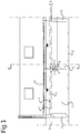
- Figure 1 shows a cross-section of a part of a manure cellar 1 provided with floor parts 2 and a discharge channel 3 consisting of discharge channel parts 6 in cross-section.
- Said cross-section is along the longitudinal direction of the floor slabs 2 which on either side connect to a discharge channel 3.
- the lower side 4 of the floor slabs 2 is essentially level.
- At the one end the thickness is greater than on the side connecting to the discharge channel 3. In that way the upper side 5 of the floor slabs 2 is at a fall towards the discharge channel 3.
- the top surface is at an angle ⁇ to the lower surface of the floor slabs 2.
- the angle will in actual practice be small in order to prevent that the manure slides along into the channel. In one embodiment said angle will be between 1 and 5 degrees. In the embodiment shown said angle is between 1 and 3 degrees.
- the floor slabs will usually be 7-20 metres long and 1-5 metres wide. At the thickest head end the slabs usually are 10-20 cm thick and at the thinnest head end 8-15 cm thick.
- the discharge channel 3 in this case is a simple channel having walls and a bottom 7. Said bottom is also at a fall, in this embodiment transverse to the fall of the floor slabs 2.
- the bottom 7 of the discharge channel 3 usually is at a fall of 0.3-2%. In this case the bottom 7 of the discharge channel 3 is at a fall of 0.4-0.7%.
- the lower side 8 of the discharge channel 3 usually is level.
- the discharge channel 3 is built up with discharge channel parts 6 of for instance 10 metres long. In one embodiment of said parts 6 the lower sides 8 connect in one plane. As a result they are easy to position on a bearing wall 9.
- the manure cellar 1 is for the collection of the thick fraction of the manure, the thin fraction is collected in a separate reservoir 10.
- the manure cellar 1 has a cellar floor 11 and side walls 12 forming a boundary of the manure cellar 1.
- the floor slabs 2 support on the side walls 12.
- the manure cellar is provided below the floor slabs and discharge channel. It will be clear that in an alternative embodiment of the stable the floor slabs 2 can also form the actual stable floor.
- a walk-on grid 13 is provided over the floor slabs 2. Details of a walk-on grid 13 have been described in the Dutch patents mentioned earlier.
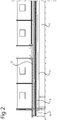
- each consecutive discharge channel part 6 has channel positioned deeper than the previous one, so that when the discharge channel parts 6 with the lower side 8 are positioned in a plane with head ends connected, a continuous discharge channel has been formed which has a bottom 7 connected at a fall.
- FIG 2 shows the side view wherein the discharge channel is shown in dotted lines.
- the bottom of the channel has a width of 7-20 cm.
- the floor slabs 2 at one outer end support on respective edges of the discharge channel 3.
- the edge of the discharge channels may be provided with a slot that is filled with a permanently elastic strip, such as for instance a hydrophilic bentonite strip, for instance Bentorub®.
- the edges can then be provided with some mortar before the floor slabs 2 are arranged.
- the floor slabs 2 can be coupled one to the other at the longitudinal sides by means of a so-called concave-convex connection so that the slabs can be connected to each other virtually seamless.
- the surfaces of the discharge channel 3 and of the floor parts that contact the urine preferably are of B65 or B80 concrete. This concrete is described in Dutch standard VBT 1995, currently NEN 8005 or NEN EN 206-1. In order to make smoothly finished pre-shaped parts the parts are often poured of self-sealing concrete.
- the self-sealing concrete usually comprises cement, a filler such as for instance fly ash or limestone flour. In addition a plasticizer is added. Then there will be question of a so-called third-generation self-sealing concrete. In this floor joist 4 and the supporters 2 such concrete is extremely suitable as due to the smooth and closed surface the urine and manure have relatively little influence.
- a first layer of concrete that has a high resistance against urine can be poured into a mould for forming the surface that will contact the urine. Subsequently the mould can be filled further with for instance the standard self-sealing concrete.
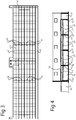
- FIGS 3-6 an overview is shown of the use of the floor parts 2 with discharge channel parts 6.
- the discharge channel 3 ends in a circumferential storage 10 for the urine and the thin liquid fraction.
- FIG 3 an embodiment of the stable is shown with the floor slabs 2 and discharge channel 3.
- a circumferential reservoir 10 for the thin fraction, for instance urine, is arranged.
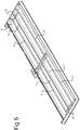
- FIG 5 a view in perspective of the stable of figure 3 is shown.
- the stand-on floor 13 with grids is shown. As described they may for instance be grids as discussed in the Dutch patents mentioned earlier. More to the left only the supporting beams of the grids are still visible.
- the floor slabs 2 with discharge channels are positioned not far below the stand-on floor.
- the supporting beams of the stand-on floor have also been left out.
- manure scrapers 30 are visible. Said manure scrapers shove the solid fraction of the manure in the longitudinal direction of the stable towards an opening (31) between the floor slabs 2 so that the solid manure fraction drops into the manure cellar 1.
- the opening (31) can be realised in different ways. A simple possibility is to leave a space between the floor parts so that the manure is able to drop between the floor parts and into the manure cellar.
- the floor parts may be provided with an opening or slit that may or may not be closable, through which the (more) solid manure can drop into the manure cellar.
- the open surface of the sum of the openings (31) is as small as possible so as to close off the manure from the outside world as quickly as possible.
- the opening (31) may for instance be arranged at every other set of floor parts. It may also be possible for instance to provide an opening or passage (31) at the outer ends of the stable. Said opening (31) as well may if so desired be closable.
- the manure pusher or manure scraper (30) may move reciprocally more often.
- the manure scraper (30) scrapes in one going direction over the floor slabs, and the manure scraper (30) is lifted from the floor slabs in the returning motion. In that way all manure is moved in one direction only.
- the manure scraper will be further discussed in figures 7-9 .
- the manure cellar can partially be seen on the outer left-hand side of figure 5 .
- An overall view can be seen in figure 6 .
- Clear are the circumferential reservoir 10 for the thin fraction of the manure and the manure cellar 1 for the thick manure fraction.
- a set of mixers is often provided in the manure cellar, as schematically shown in the top middle of figure 3 .
- FIG 7 a perspective view of a manure scraper 30 is show, from the direction in which the manure scraper 30 pushes a solid fraction of manure to the left.
- FIG 8 a perspective view of the manure scraper 30 of figure 7 is shown from the opposite direction.
- figure 9 a detail as indicated in figure 7 is enlarged.
- Manure scrapers 30 as such are known in many configurations.
- the manure scraper 30 of figure 7 comprises a frame 32 supporting a scraper bar 33.
- Scraper bar 33 is provided in such a way that it slides over a floor when the manure scraper 30 is moved in direction T. It comprises a lower end 35 that can shift over surface 5 of floor 2. It may comprise a rubber strip that shifts over the floor. In this action, the mostly solid fraction of the manure is pushed along, against the scraper surface 37.
- the manure bar extends in a longitudinal direction L, and is moved in transvers direction T, normal to the scraper bar 33.
- Scraper bar 33 comprises means for hindering, in particular preventing, displacement of manure in longitudinal direction along the manure bar 33.
- Scraper bar 33 comprises a series of dividers 34 that extend from the manure bar.
- the dividers extend in transvers direction of the manure bar, in normal direction.
- the dividers 34 extend from the scraper surface 37.
- the dividers 34 are here simple short bars or beams. These dividers 34 here comprise lower ends 36 that extend to the level of the lower ends 35 of the manure bar 33. In this way, when the manure bar 33 moves the manure, in particular over a slanted floor as described above, the manure will be prevented as much as possible from displacing in longitudinal direction along the manure bar 33.
- the dividers may have all sorts of shapes.
- the beams shown in the figures are a simple means for preventing displacement of manure in longitudinal direction along the manure bar 33.
- the scraper bar 34 comprising a series of dividers 34 is a bar that has a zigzag shape when viewed normal to a plane defined by the transverse direction and longitudinal direction (i.e., from above).
- the scraper bar 34 can have parts that are bent away from the longitudinal direction and back again, so as to provide parts of the scraper bar 33 that provide the dividers 34.
- part of the scraper bar 33 have a triangular wave shape (when viewed from above), these parts providing the dividers 34. Between the triangular wave parts, the scraper bar 33 can have straight parts.
- the bar may even have a wave shape when viewed from above.
- the dividers 34 are provisional on or of the scraper bar 33 that hinder manure from flowing or displacing.
- the manure scraper 30 comprises a scraper bar actuator (not shown).
- a scraper bar actuator (not shown).
- Other way of increasing the space between a floor and the lower end of the manure bar 33 are also possible, for instance lifting or raising the bar 33.
- the manure scraper 30 may comprise various similar scraper bars 33.
- a common frame may hold multiple scraper bars 33. These bars 33 of the common frame may be coupled to a displacement means.
- the scraper bar 33 is held by scraper frame 32.
- This scraper frame 32 here comprises guiding means, here wheels for rolling over the floor surface and wheels for rolling along guiding surfaces of a stable.
Landscapes
- Life Sciences & Earth Sciences (AREA)
- Environmental Sciences (AREA)
- Zoology (AREA)
- Animal Husbandry (AREA)
- Biodiversity & Conservation Biology (AREA)
- Treatment Of Sludge (AREA)
- Housing For Livestock And Birds (AREA)
Applications Claiming Priority (2)
| Application Number | Priority Date | Filing Date | Title |
|---|---|---|---|
| NL2013022A NL2013022B1 (en) | 2014-06-18 | 2014-06-18 | Manure scraper. |
| EP15167641.8A EP2957169B1 (de) | 2014-06-18 | 2015-05-13 | Stalldungschieber |
Related Parent Applications (1)
| Application Number | Title | Priority Date | Filing Date |
|---|---|---|---|
| EP15167641.8A Division EP2957169B1 (de) | 2014-06-18 | 2015-05-13 | Stalldungschieber |
Publications (1)
| Publication Number | Publication Date |
|---|---|
| EP3289859A1 true EP3289859A1 (de) | 2018-03-07 |
Family
ID=51656010
Family Applications (2)
| Application Number | Title | Priority Date | Filing Date |
|---|---|---|---|
| EP15167641.8A Active EP2957169B1 (de) | 2014-06-18 | 2015-05-13 | Stalldungschieber |
| EP17196466.1A Withdrawn EP3289859A1 (de) | 2014-06-18 | 2015-05-13 | Stalldungschieber |
Family Applications Before (1)
| Application Number | Title | Priority Date | Filing Date |
|---|---|---|---|
| EP15167641.8A Active EP2957169B1 (de) | 2014-06-18 | 2015-05-13 | Stalldungschieber |
Country Status (2)
| Country | Link |
|---|---|
| EP (2) | EP2957169B1 (de) |
| NL (1) | NL2013022B1 (de) |
Cited By (2)
| Publication number | Priority date | Publication date | Assignee | Title |
|---|---|---|---|---|
| WO2021022930A1 (zh) * | 2019-08-02 | 2021-02-11 | 山东新希望六和集团有限公司 | 一种带有清理机构的圈舍 |
| EP4173478A1 (de) | 2021-07-12 | 2023-05-03 | Insolute B.V. | Stall, der ein abfallbeseitigungssystem umfasst |
Families Citing this family (6)
| Publication number | Priority date | Publication date | Assignee | Title |
|---|---|---|---|---|
| CN105961209A (zh) * | 2016-08-04 | 2016-09-28 | 福建光华百斯特生态农牧发展有限公司 | 多层楼房式家畜粪尿自动清理收集系统及其收集方法 |
| CN107087546A (zh) * | 2017-03-29 | 2017-08-25 | 绍兴乐丰笼具设备有限公司 | 一种粪便处理装置 |
| CN107549024B (zh) * | 2017-10-23 | 2020-08-21 | 贵州省潘念种养殖有限公司 | 安全清洁节能牛舍粪便的方法 |
| CN110741971B (zh) * | 2019-12-09 | 2024-08-20 | 江苏省农业科学院 | 一种可调式v形双道刮粪小车 |
| CN112616715A (zh) * | 2020-12-18 | 2021-04-09 | 奉节县银青生态农业有限公司 | 一种鸡舍刮粪装置 |
| CN116267642B (zh) * | 2023-05-15 | 2023-07-21 | 晋中嘉诚种养专业合作社 | 一种畜牧养殖栏舍清洁系统 |
Citations (7)
| Publication number | Priority date | Publication date | Assignee | Title |
|---|---|---|---|---|
| EP0993769A1 (de) * | 1998-10-13 | 2000-04-19 | Sermap S.A. | Rakeleinrichtung auf einem bogenförmigen Pfad zur Abfallentsorgung |
| DE10124775C1 (de) * | 2001-05-21 | 2002-07-11 | Hermannus S F Reuver | Ausmistsystem, Ausmistschieber sowie dazugehöriges Arbeitsverfahren |
| EP2494864A1 (de) * | 2011-03-04 | 2012-09-05 | G. van Beek & Zn. Kalverstalinrichting B.V. | Stall mit Güllegrube |
| CN202819231U (zh) * | 2012-10-23 | 2013-03-27 | 新余市增鑫牧业科技有限责任公司 | 畜牧业用自动刮粪器 |
| CN202857476U (zh) * | 2012-10-25 | 2013-04-10 | 妙吉实业有限公司 | 猪舍粪尿分离装置的传动结构 |
| CN203152198U (zh) * | 2013-03-14 | 2013-08-28 | 茌平忠发畜禽设备有限公司 | 一种刮粪板 |
| CN203575290U (zh) * | 2013-11-13 | 2014-05-07 | 衢州市天元农牧科技有限公司 | 牲畜栏舍刮粪机 |
Family Cites Families (6)
| Publication number | Priority date | Publication date | Assignee | Title |
|---|---|---|---|---|
| FR2128341B1 (de) * | 1971-03-05 | 1976-01-16 | Albert Be | |
| NL9200871A (nl) | 1992-05-18 | 1993-12-16 | Paques Agri Systems B V | Stalvloersysteem. |
| NL1015290C1 (nl) | 2000-05-24 | 2001-11-27 | Boer Stalinrichtingen | Mestschuif, mestschuifsysteem en stal, voorzien van systeem. |
| US8336163B2 (en) * | 2005-04-22 | 2012-12-25 | Nuhn Industries Limited | Collection means for a mobile vacuum apparatus for the collection of liquid or semi-liquid materials |
| NL2004490C2 (nl) | 2010-03-31 | 2011-10-04 | G Van Beek & Zn Kalverstalinrichting B V | Vloerbalk voor een stalvloer en een stalvloer voorzien van een dergelijke vloerbalk. |
| NL2004491C2 (nl) | 2010-03-31 | 2011-10-04 | G Van Beek & Zn Betonindustrie B V | Vloerbalk voor een stalvloer en een stalvloer voorzien van een dergelijke vloerbalk. |
-
2014
- 2014-06-18 NL NL2013022A patent/NL2013022B1/en active
-
2015
- 2015-05-13 EP EP15167641.8A patent/EP2957169B1/de active Active
- 2015-05-13 EP EP17196466.1A patent/EP3289859A1/de not_active Withdrawn
Patent Citations (7)
| Publication number | Priority date | Publication date | Assignee | Title |
|---|---|---|---|---|
| EP0993769A1 (de) * | 1998-10-13 | 2000-04-19 | Sermap S.A. | Rakeleinrichtung auf einem bogenförmigen Pfad zur Abfallentsorgung |
| DE10124775C1 (de) * | 2001-05-21 | 2002-07-11 | Hermannus S F Reuver | Ausmistsystem, Ausmistschieber sowie dazugehöriges Arbeitsverfahren |
| EP2494864A1 (de) * | 2011-03-04 | 2012-09-05 | G. van Beek & Zn. Kalverstalinrichting B.V. | Stall mit Güllegrube |
| CN202819231U (zh) * | 2012-10-23 | 2013-03-27 | 新余市增鑫牧业科技有限责任公司 | 畜牧业用自动刮粪器 |
| CN202857476U (zh) * | 2012-10-25 | 2013-04-10 | 妙吉实业有限公司 | 猪舍粪尿分离装置的传动结构 |
| CN203152198U (zh) * | 2013-03-14 | 2013-08-28 | 茌平忠发畜禽设备有限公司 | 一种刮粪板 |
| CN203575290U (zh) * | 2013-11-13 | 2014-05-07 | 衢州市天元农牧科技有限公司 | 牲畜栏舍刮粪机 |
Cited By (2)
| Publication number | Priority date | Publication date | Assignee | Title |
|---|---|---|---|---|
| WO2021022930A1 (zh) * | 2019-08-02 | 2021-02-11 | 山东新希望六和集团有限公司 | 一种带有清理机构的圈舍 |
| EP4173478A1 (de) | 2021-07-12 | 2023-05-03 | Insolute B.V. | Stall, der ein abfallbeseitigungssystem umfasst |
Also Published As
| Publication number | Publication date |
|---|---|
| EP2957169B1 (de) | 2017-11-08 |
| EP2957169A1 (de) | 2015-12-23 |
| NL2013022B1 (en) | 2016-07-05 |
Similar Documents
| Publication | Publication Date | Title |
|---|---|---|
| EP2957169B1 (de) | Stalldungschieber | |
| EP2494864A1 (de) | Stall mit Güllegrube | |
| CN102657100A (zh) | 一种刮板式地板清粪系统及其施工方法 | |
| US7810454B2 (en) | Animal breeding plant | |
| DE102010009107A1 (de) | Verfahren zur Entfernung von Kot und Harn in Tierställen | |
| EP1673972B1 (de) | Betonfertigteilesystem für einen Stallboden, ein diesen Stallboden umfassender Stall und Verfahren zu seiner Herstellung | |
| CZ2003981A3 (cs) | Zařízení pro volné boxové ustájení s drážkovanou chodbou, příslušná prefabrikovaná betonová deska a způsob chovu zvířat | |
| EP1291325A2 (de) | Rinnenabschnitt zur Herstellung einer Rinne zur Aufnahme von Oberflächenwasser | |
| EP2236023A1 (de) | Bodenelement | |
| DE202011003507U1 (de) | Fußbodenbalken für einen Stallfußboden und mit einemderartigen Fußbodenbalken versehener Stallfußboden | |
| CN211746053U (zh) | 一种用于畜牧养殖的饲养舍 | |
| RU2386245C1 (ru) | Навозосборник | |
| DE69414638T2 (de) | Stallböden zum Gebrauch über einer Dunggrube und/oder eine Dungrinne; Bodenplatte für Stallböden; und Stall mit einem solchen Boden | |
| DE859081C (de) | Stall mit Jaucheablauf und Luftzirkulation | |
| CN117396067A (zh) | 用于动物饲养建筑物的模块化底板组件,相应的底板和建筑物,以及建立采用模块化底板组件的建筑物的方法 | |
| EP1673971B1 (de) | Betonplatten mit Struktur für einen Stallboden und ein diese Platten umfassender Stall | |
| CN110604064B (zh) | 一种依坡而建的新型多功能楼式羊舍 | |
| BE1028596B1 (nl) | Emissiearm stalvloerpaneel | |
| CN206043097U (zh) | 一种新型养殖装置 | |
| CN212344894U (zh) | 凸出式料道牛栏 | |
| CN210067277U (zh) | 一种排水型预制雨篷梁 | |
| DE19913215C2 (de) | Kuhstall | |
| CN210621387U (zh) | 一种中空状跑道预制片材 | |
| DE20011172U1 (de) | Stallgebäude für die Nutztierhaltung | |
| JP2023006598A (ja) | 牛舎における乳牛の糞尿の除去作業車の、糞尿の掻き集め作業補助用アタッチメント |
Legal Events
| Date | Code | Title | Description |
|---|---|---|---|
| PUAI | Public reference made under article 153(3) epc to a published international application that has entered the european phase |
Free format text: ORIGINAL CODE: 0009012 |
|
| STAA | Information on the status of an ep patent application or granted ep patent |
Free format text: STATUS: THE APPLICATION HAS BEEN PUBLISHED |
|
| AC | Divisional application: reference to earlier application |
Ref document number: 2957169 Country of ref document: EP Kind code of ref document: P |
|
| AK | Designated contracting states |
Kind code of ref document: A1 Designated state(s): AL AT BE BG CH CY CZ DE DK EE ES FI FR GB GR HR HU IE IS IT LI LT LU LV MC MK MT NL NO PL PT RO RS SE SI SK SM TR |
|
| STAA | Information on the status of an ep patent application or granted ep patent |
Free format text: STATUS: REQUEST FOR EXAMINATION WAS MADE |
|
| 17P | Request for examination filed |
Effective date: 20180907 |
|
| RBV | Designated contracting states (corrected) |
Designated state(s): AL AT BE BG CH CY CZ DE DK EE ES FI FR GB GR HR HU IE IS IT LI LT LU LV MC MK MT NL NO PL PT RO RS SE SI SK SM TR |
|
| STAA | Information on the status of an ep patent application or granted ep patent |
Free format text: STATUS: EXAMINATION IS IN PROGRESS |
|
| 17Q | First examination report despatched |
Effective date: 20190411 |
|
| STAA | Information on the status of an ep patent application or granted ep patent |
Free format text: STATUS: THE APPLICATION IS DEEMED TO BE WITHDRAWN |
|
| 18D | Application deemed to be withdrawn |
Effective date: 20190723 |