EP3284877A1 - Belüftete fassade - Google Patents
Belüftete fassade Download PDFInfo
- Publication number
- EP3284877A1 EP3284877A1 EP16726614.7A EP16726614A EP3284877A1 EP 3284877 A1 EP3284877 A1 EP 3284877A1 EP 16726614 A EP16726614 A EP 16726614A EP 3284877 A1 EP3284877 A1 EP 3284877A1
- Authority
- EP
- European Patent Office
- Prior art keywords
- shape
- side branch
- cladding
- battens
- anchoring elements
- Prior art date
- Legal status (The legal status is an assumption and is not a legal conclusion. Google has not performed a legal analysis and makes no representation as to the accuracy of the status listed.)
- Granted
Links
- 238000005253 cladding Methods 0.000 claims abstract description 58
- 238000004873 anchoring Methods 0.000 claims abstract description 38
- 239000002184 metal Substances 0.000 claims abstract description 10
- 230000015572 biosynthetic process Effects 0.000 claims description 10
- 238000005755 formation reaction Methods 0.000 claims description 10
- 241000743339 Agrostis Species 0.000 claims description 7
- 230000000694 effects Effects 0.000 description 6
- 239000010454 slate Substances 0.000 description 5
- 239000004568 cement Substances 0.000 description 3
- 239000000835 fiber Substances 0.000 description 3
- 239000004033 plastic Substances 0.000 description 3
- 239000010438 granite Substances 0.000 description 2
- 238000009423 ventilation Methods 0.000 description 2
- 239000000919 ceramic Substances 0.000 description 1
- 239000002131 composite material Substances 0.000 description 1
- 238000010276 construction Methods 0.000 description 1
- 239000003365 glass fiber Substances 0.000 description 1
- 238000009434 installation Methods 0.000 description 1
- 239000000463 material Substances 0.000 description 1
- 230000002035 prolonged effect Effects 0.000 description 1
- 239000011347 resin Substances 0.000 description 1
- 229920005989 resin Polymers 0.000 description 1
- 239000004575 stone Substances 0.000 description 1
- 230000000007 visual effect Effects 0.000 description 1
- 239000002023 wood Substances 0.000 description 1
Images


Classifications
-
- E—FIXED CONSTRUCTIONS
- E04—BUILDING
- E04F—FINISHING WORK ON BUILDINGS, e.g. STAIRS, FLOORS
- E04F13/00—Coverings or linings, e.g. for walls or ceilings
- E04F13/07—Coverings or linings, e.g. for walls or ceilings composed of covering or lining elements; Sub-structures therefor; Fastening means therefor
- E04F13/08—Coverings or linings, e.g. for walls or ceilings composed of covering or lining elements; Sub-structures therefor; Fastening means therefor composed of a plurality of similar covering or lining elements
- E04F13/0801—Separate fastening elements
- E04F13/0803—Separate fastening elements with load-supporting elongated furring elements between wall and covering elements
- E04F13/0805—Separate fastening elements with load-supporting elongated furring elements between wall and covering elements with additional fastening elements between furring elements and the wall
-
- E—FIXED CONSTRUCTIONS
- E04—BUILDING
- E04F—FINISHING WORK ON BUILDINGS, e.g. STAIRS, FLOORS
- E04F13/00—Coverings or linings, e.g. for walls or ceilings
- E04F13/07—Coverings or linings, e.g. for walls or ceilings composed of covering or lining elements; Sub-structures therefor; Fastening means therefor
- E04F13/08—Coverings or linings, e.g. for walls or ceilings composed of covering or lining elements; Sub-structures therefor; Fastening means therefor composed of a plurality of similar covering or lining elements
- E04F13/0801—Separate fastening elements
- E04F13/0803—Separate fastening elements with load-supporting elongated furring elements between wall and covering elements
- E04F13/081—Separate fastening elements with load-supporting elongated furring elements between wall and covering elements with additional fastening elements between furring elements and covering elements
- E04F13/0812—Separate fastening elements with load-supporting elongated furring elements between wall and covering elements with additional fastening elements between furring elements and covering elements fixed by means of spring action
-
- E—FIXED CONSTRUCTIONS
- E04—BUILDING
- E04F—FINISHING WORK ON BUILDINGS, e.g. STAIRS, FLOORS
- E04F13/00—Coverings or linings, e.g. for walls or ceilings
- E04F13/07—Coverings or linings, e.g. for walls or ceilings composed of covering or lining elements; Sub-structures therefor; Fastening means therefor
- E04F13/08—Coverings or linings, e.g. for walls or ceilings composed of covering or lining elements; Sub-structures therefor; Fastening means therefor composed of a plurality of similar covering or lining elements
- E04F13/0801—Separate fastening elements
- E04F13/0803—Separate fastening elements with load-supporting elongated furring elements between wall and covering elements
- E04F13/081—Separate fastening elements with load-supporting elongated furring elements between wall and covering elements with additional fastening elements between furring elements and covering elements
- E04F13/0821—Separate fastening elements with load-supporting elongated furring elements between wall and covering elements with additional fastening elements between furring elements and covering elements the additional fastening elements located in-between two adjacent covering elements
- E04F13/0825—Separate fastening elements with load-supporting elongated furring elements between wall and covering elements with additional fastening elements between furring elements and covering elements the additional fastening elements located in-between two adjacent covering elements engaging side holes preformed into the covering elements
-
- E—FIXED CONSTRUCTIONS
- E04—BUILDING
- E04F—FINISHING WORK ON BUILDINGS, e.g. STAIRS, FLOORS
- E04F13/00—Coverings or linings, e.g. for walls or ceilings
- E04F13/07—Coverings or linings, e.g. for walls or ceilings composed of covering or lining elements; Sub-structures therefor; Fastening means therefor
- E04F13/08—Coverings or linings, e.g. for walls or ceilings composed of covering or lining elements; Sub-structures therefor; Fastening means therefor composed of a plurality of similar covering or lining elements
- E04F13/0801—Separate fastening elements
- E04F13/0803—Separate fastening elements with load-supporting elongated furring elements between wall and covering elements
- E04F13/081—Separate fastening elements with load-supporting elongated furring elements between wall and covering elements with additional fastening elements between furring elements and covering elements
- E04F13/0821—Separate fastening elements with load-supporting elongated furring elements between wall and covering elements with additional fastening elements between furring elements and covering elements the additional fastening elements located in-between two adjacent covering elements
- E04F13/0826—Separate fastening elements with load-supporting elongated furring elements between wall and covering elements with additional fastening elements between furring elements and covering elements the additional fastening elements located in-between two adjacent covering elements engaging side grooves running along the whole length of the covering elements
-
- E—FIXED CONSTRUCTIONS
- E04—BUILDING
- E04F—FINISHING WORK ON BUILDINGS, e.g. STAIRS, FLOORS
- E04F13/00—Coverings or linings, e.g. for walls or ceilings
- E04F13/07—Coverings or linings, e.g. for walls or ceilings composed of covering or lining elements; Sub-structures therefor; Fastening means therefor
- E04F13/08—Coverings or linings, e.g. for walls or ceilings composed of covering or lining elements; Sub-structures therefor; Fastening means therefor composed of a plurality of similar covering or lining elements
- E04F13/0801—Separate fastening elements
- E04F13/0803—Separate fastening elements with load-supporting elongated furring elements between wall and covering elements
- E04F13/081—Separate fastening elements with load-supporting elongated furring elements between wall and covering elements with additional fastening elements between furring elements and covering elements
- E04F13/083—Hooking means on the back side of the covering elements
-
- E—FIXED CONSTRUCTIONS
- E04—BUILDING
- E04F—FINISHING WORK ON BUILDINGS, e.g. STAIRS, FLOORS
- E04F13/00—Coverings or linings, e.g. for walls or ceilings
- E04F13/07—Coverings or linings, e.g. for walls or ceilings composed of covering or lining elements; Sub-structures therefor; Fastening means therefor
- E04F13/08—Coverings or linings, e.g. for walls or ceilings composed of covering or lining elements; Sub-structures therefor; Fastening means therefor composed of a plurality of similar covering or lining elements
- E04F13/0801—Separate fastening elements
- E04F13/0832—Separate fastening elements without load-supporting elongated furring elements between wall and covering elements
-
- E—FIXED CONSTRUCTIONS
- E04—BUILDING
- E04F—FINISHING WORK ON BUILDINGS, e.g. STAIRS, FLOORS
- E04F13/00—Coverings or linings, e.g. for walls or ceilings
- E04F13/07—Coverings or linings, e.g. for walls or ceilings composed of covering or lining elements; Sub-structures therefor; Fastening means therefor
- E04F13/08—Coverings or linings, e.g. for walls or ceilings composed of covering or lining elements; Sub-structures therefor; Fastening means therefor composed of a plurality of similar covering or lining elements
- E04F13/0864—Coverings or linings, e.g. for walls or ceilings composed of covering or lining elements; Sub-structures therefor; Fastening means therefor composed of a plurality of similar covering or lining elements composed of superposed elements which overlap each other and of which the flat outer surface includes an acute angle with the surface to cover
-
- E—FIXED CONSTRUCTIONS
- E04—BUILDING
- E04F—FINISHING WORK ON BUILDINGS, e.g. STAIRS, FLOORS
- E04F13/00—Coverings or linings, e.g. for walls or ceilings
- E04F13/07—Coverings or linings, e.g. for walls or ceilings composed of covering or lining elements; Sub-structures therefor; Fastening means therefor
- E04F13/08—Coverings or linings, e.g. for walls or ceilings composed of covering or lining elements; Sub-structures therefor; Fastening means therefor composed of a plurality of similar covering or lining elements
- E04F13/14—Coverings or linings, e.g. for walls or ceilings composed of covering or lining elements; Sub-structures therefor; Fastening means therefor composed of a plurality of similar covering or lining elements stone or stone-like materials, e.g. ceramics concrete; of glass or with an outer layer of stone or stone-like materials or glass
- E04F13/142—Coverings or linings, e.g. for walls or ceilings composed of covering or lining elements; Sub-structures therefor; Fastening means therefor composed of a plurality of similar covering or lining elements stone or stone-like materials, e.g. ceramics concrete; of glass or with an outer layer of stone or stone-like materials or glass with an outer layer of ceramics or clays
Definitions
- the present invention relates to a ventilated façade, made up of cladding parts, for example, slate, natural stone, ceramic or metal plates, plastic, composite panels, cement fiber, etc., that are assembled on horizontal battens fixed on vertical battens anchored to the wall to be cladded or directly on said wall.
- the assembly of the cladding parts on the battens is carried out by means of hook anchoring elements hanging from said battens.
- Ventilated façades are those having an air chamber between the cladding and the wall of the façade. This air chamber creates the so-called “chimney effect”, providing continuous ventilation due to temperature differences between the outside air and the chamber air.
- façades are known in which the cladding is made up of, for example, slate parts, that are assembled by means of anchoring elements, made of sheet metal or wire, on horizontal battens, generally made of wood, fixed to the wall of the façade.
- patent documents CH 659679 and EP0167032 can be mentioned, in which the assembly of the cladding parts is carried out by means of anchoring parts comprising a straight section that finishes at its ends in bents heading in opposite directions, in the form of hooks of different width.
- anchoring parts comprising a straight section that finishes at its ends in bents heading in opposite directions, in the form of hooks of different width.
- the anchoring part hangs from the battens, and the upper edge of a panel belonging to a lower row of panels is introduced between the batten and the straight section of the anchoring part, while the lower edge of a panel belonging to an upper row of panels is supported on the hook with a smaller width.
- the external branch of the hook with a larger width can be prolonged sideways in a loop which is housed in the batten and which serves as upward support means of the hook on said batten.
- the present invention relates to a ventilated façade made up of a covering which is formed by cladding parts of any type (slate, granite, plastic, sheet metal, cement fiber, etc.), which are assembled on metallic battens by means of anchoring elements made of wire or sheet metal.
- the façade covering allows achieving a durable finish with a good visual appearance, in comparison with claddings with wooden or pre-fabricated panels.
- Metallic battens offer improved performance and resistance against humidity and possible fires with respect to wooden battens.
- the anchoring elements made of wire, metallic rod or sheet metal, are formed such that they have greater capacity to absorb or adjust to possible differences in the thicknesses of the slate parts, which allows achieving a practically flat visible surface.
- the ventilated façade of the invention is of the previously indicated type, formed by cladding parts that are assembled on horizontal battens by means of anchoring elements made of wire or sheet metal hanging from the battens through openings which said battens have.
- the anchoring elements are U-shaped and hang in an inverted position from the horizontal battens, with a rear side branch introduced through the openings of the battens, and a front side branch running downwards along the front of the batten.
- the aforementioned front side branch finishes in an upward bent, forming an outer hook on which there will be supported the lower edge of a cladding part, belonging to an upper row of cladding parts.
- the rear side branch introduced through the openings of the battens, has an inner projection establishing with the front branch of the U shape a narrowing having a width smaller than the thickness of the cladding parts. The upper edge of a cladding part belonging to a lower row of cladding parts is introduced through this narrowing.
- the aforementioned inner projection of the rear branch of the U shape can be obtained by means of transverse formations made on said rear side branch. Furthermore, the inner projection can consist of a spring which is fixed on the inner surface of the rear side branch of the U shape.
- the horizontal battens on which the cladding parts with an angular profile are fixed they are made up of three sections, a central section and two end sections perpendicular to the central section and heading in opposite directions. Along the outer surface of one of the end sections these battens have a flap which is parallel to the central section of the batten.
- the openings are located on the aforementioned flap, through which openings the rear branch of the U shape forming the anchoring elements is introduced. Furthermore this flap finishes in a longitudinal support assuring the positioning of the anchoring elements on the batten.
- the transverse formations of the rear side branch of the anchoring elements can consist of an end bent heading towards the inside of the U shape and which will define a narrowing in the mouth of said U shape, which will be elastically supported on the upper edge of a cladding part introduced between said bent and the front side branch of the U shape.
- the transverse formations of the rear side branch of the U shape can consist of intermediate bents, also heading towards the inside of the U shape, which bents forming inside the U shape an inner step which will be elastically supported against the upper edge of a cladding part introduced between the mentioned intermediate bent and the front side branch of the U shape.
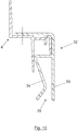
- Figure 1 shows in a partial vertical section view a ventilated façade formed by a covering (1), which is assembled on the wall (2) of the façade.
- the covering (1) is made up of parts (3-3') that are assembled in horizontal alignments on horizontal battens (4) which are fixed to vertical battens (4') anchored to the wall (2) of the façade, or directly on said wall.
- the assembly of the cladding parts is carried out by means of anchoring elements (5) which hang from the battens (4).
- the cladding parts (3-3') can be of any type, for example, of slate, granite, plastic, metal, cement fiber, etc.
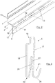
- the battens (4), Figure 2 are of metallic type and have an angular profile made up of three consecutive sections, a central section (6) and two end sections (7 and 8) perpendicular to the central section (6) and heading in opposite directions.
- a flap (10) projects parallel and close to the section (6), the section of which ends in a longitudinal support (11) for the anchoring elements (5), in the shape of an inverted channel with walls of different height.
- the base (12) of this channel is approximately coplanar with the central section (6) of the batten (4).
- the flap (10) has, along its length, openings (13) that will be used for hanging the anchoring elements (5).
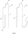
- the anchoring elements (5'), Figures 3 to 7 have a U shape with considerably parallel branches (17 and 18). These anchoring elements hang in an inverted position from the horizontal battens (4), Figure 1 , with the side branch (18), called the rear side branch, being introduced through the openings (13), while the side branch (17), called the front side branch, running along the front of the batten.
- the central branch (19) of the U shape has an intermediate bent, establishing sections of different depths which can be coupled on the flap (10) and support (11) of the horizontal batten.
- the front side branch (17) finishes in an upward outer bent (20), forming a hook (21) on which there is supported the lower edge of a cladding part (3), belonging to an upper row of cladding parts.
- the rear side branch (18) has formations which can be defined by end bents in the shape of a hook (22), Figures 3 and 4 , heading towards the inside of said U shape, or in the shape of an inner tab (23), Figure 6 .
- the mentioned formations can also be defined by intermediate bents (24-25), Figures 5 and 7 .
- the mentioned formations establish a narrowing in the inside of the U shape which will be elastically supported against the upper portion of a cladding part (3') belonging to a lower row of cladding parts partially introduced in the U shape, as shown in Figure 1 .
- the hook (22), the tab (23) and the bents (24 and 25) establish a narrowing inside the U shape providing a spring effect compressing the cladding part (3') against the front side branch (17) of the U shape.
- the cladding parts (3') will be pushed against the parts (3), which allows absorbing possible differences in thicknesses between cladding parts, thereby achieving in each row of cladding parts a virtually flat outer surface.
- the end branch (26) of the hook (22) can be provided with a cladding (27) made of an elastically compressible material or with a deformation (27'), Figure 4 , to increase the aforementioned spring effect and provide improved support to the cladding parts (3').
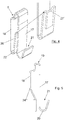
- the anchoring element of Figures 3 and 4 can be sub-divided in two independent parts (28 and 29), Figure 8 , both in U shape, which can be hung from different openings (13) of the horizontal battens (4), through their rear side branch (18).
- the part (29) will be used for supporting the lower edge of cladding parts (3), through its hook (21), while the part (28) will provide, through the hook (22), the spring effect pushing the parts (3') of a lower row against the parts (3) of an upper row.
- the battens (4) are thus fixed in a horizontal position on vertical battens (4') anchored to the wall (2), or directly on said wall.
- the anchoring elements (5) are assembled by introducing the branch (18) and the hook (22) through the openings (13) of the batten (4).
- the cladding part (3) of an upper row of parts is supported on the hook (21), through the lower edge of said parts (3).
- the anchoring element is supported on the end section (8) of the battens (4) through the branch (18).
- the central branch (19) of the anchoring part has a shape which allows achieving safe seating on the batten (4).
- the inner narrowing of the U shape can also be achieved by means of arranging a spring (30) fixed to the inner surface of the rear branch (18) of the U shape, Figure 8 .
- the upper edge of a cladding part (3') belonging to a lower row of cladding parts is introduced between this spring (30) and the front branch (17) of the U shape.
- the cladding parts can incorporate a glass fiber mesh, fixed by means of resin, for example.
- Intermediate support profiles (31), Figure 1 can also be installed between the cladding parts (3-3') and the vertical battens (4').
- auxiliary parts (32) with the profile shown in Figure 10 , fixed by means of screwing them onto the batten (4), can be used.
- the cladding parts are introduced between the tabs (33 and 34), forming an inverted clamp (35), and may or may not be fixed with screws through the tab (33), depending on the particular installation conditions of the cladding parts in each case.
- Figure 11 shows, for the same purpose, an auxiliary part (36) in an inverted U shape, which is assembled on the horizontal battens in the same way as that described in reference to Figure 1 , and between the branches (37 and 38) of which, forming an inverted clamp (35), there is introduced the upper edge of cladding parts (3-3') which can be fixed by means of screws (39).
Landscapes
- Engineering & Computer Science (AREA)
- Architecture (AREA)
- Civil Engineering (AREA)
- Structural Engineering (AREA)
- Chemical & Material Sciences (AREA)
- Ceramic Engineering (AREA)
- Dispersion Chemistry (AREA)
- Finishing Walls (AREA)
Applications Claiming Priority (2)
| Application Number | Priority Date | Filing Date | Title |
|---|---|---|---|
| ES201530505A ES2586736B1 (es) | 2015-04-15 | 2015-04-15 | Fachada ventilada |
| PCT/ES2016/070240 WO2016166395A1 (es) | 2015-04-15 | 2016-04-08 | Fachada ventilada |
Publications (2)
| Publication Number | Publication Date |
|---|---|
| EP3284877A1 true EP3284877A1 (de) | 2018-02-21 |
| EP3284877B1 EP3284877B1 (de) | 2018-11-14 |
Family
ID=56097148
Family Applications (1)
| Application Number | Title | Priority Date | Filing Date |
|---|---|---|---|
| EP16726614.7A Active EP3284877B1 (de) | 2015-04-15 | 2016-04-08 | Hinterlüftete fassade |
Country Status (6)
| Country | Link |
|---|---|
| US (1) | US9869097B2 (de) |
| EP (1) | EP3284877B1 (de) |
| CA (1) | CA2979613C (de) |
| DK (1) | DK3284877T3 (de) |
| ES (2) | ES2586736B1 (de) |
| WO (1) | WO2016166395A1 (de) |
Families Citing this family (7)
| Publication number | Priority date | Publication date | Assignee | Title |
|---|---|---|---|---|
| US10316524B2 (en) * | 2015-05-21 | 2019-06-11 | Komproment Holding Af 2007 Aps | Rail system |
| US10151117B2 (en) * | 2016-12-21 | 2018-12-11 | Peter Kuelker | Hanger for precast cladding panels, and precast panel incorporating same |
| US20180274245A1 (en) * | 2017-03-27 | 2018-09-27 | KPA Studios Inc | Cassette framing system |
| GB2565266B (en) | 2017-06-20 | 2021-08-25 | Ash & Lacy Holdings Ltd | Mounting rail |
| EP3710648A4 (de) * | 2017-11-17 | 2021-05-05 | Rockwool International A/S | Aufhängungssystem |
| NO346069B1 (en) * | 2020-08-14 | 2022-01-31 | Spilka Ind As | A wall panel mounting system comprising a wall panel mounting device, such a device and a method for mounting such a wall panel |
| CN113738048A (zh) * | 2021-09-27 | 2021-12-03 | 洛阳九朝文物复制品有限公司 | 一种干挂钩及干挂施工工艺 |
Family Cites Families (19)
| Publication number | Priority date | Publication date | Assignee | Title |
|---|---|---|---|---|
| US2511083A (en) * | 1946-08-30 | 1950-06-13 | Byron Nugent | Assembly of roofing and siding units |
| FR2433087A1 (fr) * | 1978-08-07 | 1980-03-07 | Safama | Dispositif pour fixer sur une structure murale, et a distance de celle-ci, un revetement constitue d'une pluralite de panneaux |
| DE3329812A1 (de) * | 1983-08-18 | 1985-02-28 | Profil-Vertrieb Gmbh, 7560 Gaggenau | Fassadenbekleidung |
| DE3424375C2 (de) | 1984-07-03 | 1997-01-16 | Bwm Duebel & Montagetech | Aufhängevorrichtung für Wandplatten mit einer an einer Wand befestigbaren Querleiste und daran eingehängten, die Wandplatten tragenden Haken |
| CH659679A5 (en) | 1986-04-09 | 1987-02-13 | August Braendli | Retaining device for facade claddings or internal claddings of walls and internal claddings or external claddings of ceilings |
| FR2607171B1 (fr) * | 1986-11-24 | 1991-08-30 | Smac Acieroid | Lisse pour revetement de facade et revetement de facade utilisant de telles lisses |
| FR2614340B1 (fr) * | 1987-04-23 | 1989-07-28 | Smac Acieroid | Dispositif de fixation des plaques d'un revetement de facade |
| NL192623C (nl) * | 1987-05-05 | 1997-11-04 | Randstede Bouwconsult B V | Gevelbekleding en bevestigingselementen en gevelplaat daarvoor. |
| DE4141668C2 (de) * | 1991-12-17 | 1996-08-01 | Annawerk Gmbh | Außenfassade aus Fassadenplatten mit doppelwandigem Aufbau |
| DE19718716C2 (de) * | 1997-05-02 | 2002-08-01 | Max Gerhaher | Vorgehängte Fassadenkonstruktion |
| DE19720016C2 (de) * | 1997-05-13 | 1999-04-01 | Gerhaher Max | Vorgehängte Fassadenkonstruktion |
| US7441382B2 (en) * | 2002-10-18 | 2008-10-28 | Certainteed Corporation | Clapboard siding installation clip and method of installing clapboard siding |
| DE102006033045A1 (de) * | 2006-07-14 | 2008-01-17 | Moeding Keramikfassaden Gmbh | Vorgehängte Fassadenkonstruktion |
| DE102009040319A1 (de) * | 2009-09-05 | 2011-03-10 | LängleGlas GmbH | Schuppenhalter für die Schnellmontage von Platten und Glastafeln sowie Verfahren zur Montage eines Schuppenhalters |
| DE202010000520U1 (de) * | 2010-03-31 | 2010-08-05 | Technische Universität Darmstadt | Fassadenverkleidung und Fassadenmodul für eine Fassadenverkleidung einer Außenfassade eines Gebäudes |
| ES2657612T3 (es) * | 2010-05-28 | 2018-03-06 | The Diller Corporation | Sistema de revestimiento de laminados para construcción |
| NZ608287A (en) * | 2010-10-28 | 2014-06-27 | Cladding Systems Int Ltd | Cladding rail, cladding fixing system and method |
| JP5756366B2 (ja) * | 2011-07-28 | 2015-07-29 | ニチハ株式会社 | 胴縁留め付け部材及びそれを用いた施工構造、施工方法 |
| GB2502314A (en) * | 2012-05-24 | 2013-11-27 | Cep Claddings Ltd | Method of prefabricating a cladding assembly |
-
2015
- 2015-04-15 ES ES201530505A patent/ES2586736B1/es active Active
-
2016
- 2016-04-08 WO PCT/ES2016/070240 patent/WO2016166395A1/es active Application Filing
- 2016-04-08 DK DK16726614.7T patent/DK3284877T3/en active
- 2016-04-08 ES ES16726614T patent/ES2710786T3/es active Active
- 2016-04-08 CA CA2979613A patent/CA2979613C/en active Active
- 2016-04-08 EP EP16726614.7A patent/EP3284877B1/de active Active
- 2016-04-08 US US15/519,045 patent/US9869097B2/en active Active
Also Published As
| Publication number | Publication date |
|---|---|
| EP3284877B1 (de) | 2018-11-14 |
| US9869097B2 (en) | 2018-01-16 |
| DK3284877T3 (en) | 2019-03-04 |
| ES2710786T3 (es) | 2019-04-26 |
| ES2586736B1 (es) | 2017-09-07 |
| ES2586736A2 (es) | 2016-10-18 |
| WO2016166395A1 (es) | 2016-10-20 |
| CA2979613A1 (en) | 2016-10-20 |
| ES2586736R1 (es) | 2016-11-10 |
| US20170226747A1 (en) | 2017-08-10 |
| CA2979613C (en) | 2022-01-25 |
Similar Documents
| Publication | Publication Date | Title |
|---|---|---|
| EP3284877B1 (de) | Hinterlüftete fassade | |
| US7984593B2 (en) | Surface facing system | |
| KR20170032837A (ko) | 외장 구조 | |
| US3300926A (en) | Wall paneling system | |
| KR20070009265A (ko) | 브라켓의 걸어맞춤을 이용한 실내벽의 패널 설치구조 | |
| JP5393135B2 (ja) | 軒先構造 | |
| KR101081801B1 (ko) | 강성이 보강된 커튼월 | |
| KR100928436B1 (ko) | 조립식 경량패널 및 조립식 경량패널 설치방법 | |
| US10024054B2 (en) | Facade construction | |
| US3452500A (en) | Wall paneling system | |
| KR200412570Y1 (ko) | 알루미늄 외장판넬 | |
| US20140090326A1 (en) | Aesthetic wall facade systems, devices, and methods | |
| KR20130012422A (ko) | 벽면에 내/외장재로 시공되는 조립식 패널 구조체 및 그 시공방법 | |
| KR100929227B1 (ko) | 마감패널 조립체 | |
| CN209483139U (zh) | 一种超长无立柱卧棂百叶窗结构 | |
| KR100843933B1 (ko) | 루버 | |
| KR101963719B1 (ko) | 환기용 루버 설치구조 | |
| KR101223465B1 (ko) | 조립형 돌출마감재를 이용한 창호프레임 시공방법 | |
| KR102095788B1 (ko) | 외장패널 설치구조 | |
| RU56428U1 (ru) | Фасадная плита "ра-дом" | |
| KR100514381B1 (ko) | 방충망레일 일체형 공틀 | |
| SE408198B (sv) | Fasadbeklednad | |
| KR200320187Y1 (ko) | 방충망레일 일체형 공틀 | |
| JP4000119B2 (ja) | 踊り場支持用増壁パネルの構造 | |
| KR101312373B1 (ko) | 건축물 루버 고정용 조립체 |
Legal Events
| Date | Code | Title | Description |
|---|---|---|---|
| STAA | Information on the status of an ep patent application or granted ep patent |
Free format text: STATUS: THE INTERNATIONAL PUBLICATION HAS BEEN MADE |
|
| PUAI | Public reference made under article 153(3) epc to a published international application that has entered the european phase |
Free format text: ORIGINAL CODE: 0009012 |
|
| STAA | Information on the status of an ep patent application or granted ep patent |
Free format text: STATUS: REQUEST FOR EXAMINATION WAS MADE |
|
| 17P | Request for examination filed |
Effective date: 20170915 |
|
| AK | Designated contracting states |
Kind code of ref document: A1 Designated state(s): AL AT BE BG CH CY CZ DE DK EE ES FI FR GB GR HR HU IE IS IT LI LT LU LV MC MK MT NL NO PL PT RO RS SE SI SK SM TR |
|
| AX | Request for extension of the european patent |
Extension state: BA ME |
|
| GRAP | Despatch of communication of intention to grant a patent |
Free format text: ORIGINAL CODE: EPIDOSNIGR1 |
|
| STAA | Information on the status of an ep patent application or granted ep patent |
Free format text: STATUS: GRANT OF PATENT IS INTENDED |
|
| RIC1 | Information provided on ipc code assigned before grant |
Ipc: E04F 13/14 20060101ALN20180606BHEP Ipc: E04F 13/08 20060101AFI20180606BHEP |
|
| DAV | Request for validation of the european patent (deleted) | ||
| DAX | Request for extension of the european patent (deleted) | ||
| INTG | Intention to grant announced |
Effective date: 20180621 |
|
| GRAS | Grant fee paid |
Free format text: ORIGINAL CODE: EPIDOSNIGR3 |
|
| GRAA | (expected) grant |
Free format text: ORIGINAL CODE: 0009210 |
|
| STAA | Information on the status of an ep patent application or granted ep patent |
Free format text: STATUS: THE PATENT HAS BEEN GRANTED |
|
| AK | Designated contracting states |
Kind code of ref document: B1 Designated state(s): AL AT BE BG CH CY CZ DE DK EE ES FI FR GB GR HR HU IE IS IT LI LT LU LV MC MK MT NL NO PL PT RO RS SE SI SK SM TR |
|
| REG | Reference to a national code |
Ref country code: CH Ref legal event code: EP Ref country code: AT Ref legal event code: REF Ref document number: 1064993 Country of ref document: AT Kind code of ref document: T Effective date: 20181115 |
|
| REG | Reference to a national code |
Ref country code: DE Ref legal event code: R096 Ref document number: 602016007215 Country of ref document: DE |
|
| REG | Reference to a national code |
Ref country code: IE Ref legal event code: FG4D |
|
| REG | Reference to a national code |
Ref country code: DK Ref legal event code: T3 Effective date: 20190225 |
|
| REG | Reference to a national code |
Ref country code: NL Ref legal event code: FP |
|
| REG | Reference to a national code |
Ref country code: LT Ref legal event code: MG4D |
|
| REG | Reference to a national code |
Ref country code: AT Ref legal event code: MK05 Ref document number: 1064993 Country of ref document: AT Kind code of ref document: T Effective date: 20181114 |
|
| REG | Reference to a national code |
Ref country code: ES Ref legal event code: FG2A Ref document number: 2710786 Country of ref document: ES Kind code of ref document: T3 Effective date: 20190426 |
|
| REG | Reference to a national code |
Ref country code: NO Ref legal event code: T2 Effective date: 20181114 |
|
| PG25 | Lapsed in a contracting state [announced via postgrant information from national office to epo] |
Ref country code: LT Free format text: LAPSE BECAUSE OF FAILURE TO SUBMIT A TRANSLATION OF THE DESCRIPTION OR TO PAY THE FEE WITHIN THE PRESCRIBED TIME-LIMIT Effective date: 20181114 Ref country code: AT Free format text: LAPSE BECAUSE OF FAILURE TO SUBMIT A TRANSLATION OF THE DESCRIPTION OR TO PAY THE FEE WITHIN THE PRESCRIBED TIME-LIMIT Effective date: 20181114 Ref country code: HR Free format text: LAPSE BECAUSE OF FAILURE TO SUBMIT A TRANSLATION OF THE DESCRIPTION OR TO PAY THE FEE WITHIN THE PRESCRIBED TIME-LIMIT Effective date: 20181114 Ref country code: BG Free format text: LAPSE BECAUSE OF FAILURE TO SUBMIT A TRANSLATION OF THE DESCRIPTION OR TO PAY THE FEE WITHIN THE PRESCRIBED TIME-LIMIT Effective date: 20190214 Ref country code: LV Free format text: LAPSE BECAUSE OF FAILURE TO SUBMIT A TRANSLATION OF THE DESCRIPTION OR TO PAY THE FEE WITHIN THE PRESCRIBED TIME-LIMIT Effective date: 20181114 Ref country code: FI Free format text: LAPSE BECAUSE OF FAILURE TO SUBMIT A TRANSLATION OF THE DESCRIPTION OR TO PAY THE FEE WITHIN THE PRESCRIBED TIME-LIMIT Effective date: 20181114 Ref country code: IS Free format text: LAPSE BECAUSE OF FAILURE TO SUBMIT A TRANSLATION OF THE DESCRIPTION OR TO PAY THE FEE WITHIN THE PRESCRIBED TIME-LIMIT Effective date: 20190314 |
|
| PG25 | Lapsed in a contracting state [announced via postgrant information from national office to epo] |
Ref country code: GR Free format text: LAPSE BECAUSE OF FAILURE TO SUBMIT A TRANSLATION OF THE DESCRIPTION OR TO PAY THE FEE WITHIN THE PRESCRIBED TIME-LIMIT Effective date: 20190215 Ref country code: PT Free format text: LAPSE BECAUSE OF FAILURE TO SUBMIT A TRANSLATION OF THE DESCRIPTION OR TO PAY THE FEE WITHIN THE PRESCRIBED TIME-LIMIT Effective date: 20190314 Ref country code: RS Free format text: LAPSE BECAUSE OF FAILURE TO SUBMIT A TRANSLATION OF THE DESCRIPTION OR TO PAY THE FEE WITHIN THE PRESCRIBED TIME-LIMIT Effective date: 20181114 Ref country code: AL Free format text: LAPSE BECAUSE OF FAILURE TO SUBMIT A TRANSLATION OF THE DESCRIPTION OR TO PAY THE FEE WITHIN THE PRESCRIBED TIME-LIMIT Effective date: 20181114 Ref country code: SE Free format text: LAPSE BECAUSE OF FAILURE TO SUBMIT A TRANSLATION OF THE DESCRIPTION OR TO PAY THE FEE WITHIN THE PRESCRIBED TIME-LIMIT Effective date: 20181114 |
|
| PG25 | Lapsed in a contracting state [announced via postgrant information from national office to epo] |
Ref country code: PL Free format text: LAPSE BECAUSE OF FAILURE TO SUBMIT A TRANSLATION OF THE DESCRIPTION OR TO PAY THE FEE WITHIN THE PRESCRIBED TIME-LIMIT Effective date: 20181114 Ref country code: CZ Free format text: LAPSE BECAUSE OF FAILURE TO SUBMIT A TRANSLATION OF THE DESCRIPTION OR TO PAY THE FEE WITHIN THE PRESCRIBED TIME-LIMIT Effective date: 20181114 Ref country code: IT Free format text: LAPSE BECAUSE OF FAILURE TO SUBMIT A TRANSLATION OF THE DESCRIPTION OR TO PAY THE FEE WITHIN THE PRESCRIBED TIME-LIMIT Effective date: 20181114 |
|
| REG | Reference to a national code |
Ref country code: DE Ref legal event code: R097 Ref document number: 602016007215 Country of ref document: DE |
|
| PG25 | Lapsed in a contracting state [announced via postgrant information from national office to epo] |
Ref country code: SK Free format text: LAPSE BECAUSE OF FAILURE TO SUBMIT A TRANSLATION OF THE DESCRIPTION OR TO PAY THE FEE WITHIN THE PRESCRIBED TIME-LIMIT Effective date: 20181114 Ref country code: SM Free format text: LAPSE BECAUSE OF FAILURE TO SUBMIT A TRANSLATION OF THE DESCRIPTION OR TO PAY THE FEE WITHIN THE PRESCRIBED TIME-LIMIT Effective date: 20181114 Ref country code: EE Free format text: LAPSE BECAUSE OF FAILURE TO SUBMIT A TRANSLATION OF THE DESCRIPTION OR TO PAY THE FEE WITHIN THE PRESCRIBED TIME-LIMIT Effective date: 20181114 Ref country code: RO Free format text: LAPSE BECAUSE OF FAILURE TO SUBMIT A TRANSLATION OF THE DESCRIPTION OR TO PAY THE FEE WITHIN THE PRESCRIBED TIME-LIMIT Effective date: 20181114 |
|
| PLBE | No opposition filed within time limit |
Free format text: ORIGINAL CODE: 0009261 |
|
| STAA | Information on the status of an ep patent application or granted ep patent |
Free format text: STATUS: NO OPPOSITION FILED WITHIN TIME LIMIT |
|
| 26N | No opposition filed |
Effective date: 20190815 |
|
| PG25 | Lapsed in a contracting state [announced via postgrant information from national office to epo] |
Ref country code: MC Free format text: LAPSE BECAUSE OF FAILURE TO SUBMIT A TRANSLATION OF THE DESCRIPTION OR TO PAY THE FEE WITHIN THE PRESCRIBED TIME-LIMIT Effective date: 20181114 |
|
| PG25 | Lapsed in a contracting state [announced via postgrant information from national office to epo] |
Ref country code: TR Free format text: LAPSE BECAUSE OF FAILURE TO SUBMIT A TRANSLATION OF THE DESCRIPTION OR TO PAY THE FEE WITHIN THE PRESCRIBED TIME-LIMIT Effective date: 20181114 |
|
| PG25 | Lapsed in a contracting state [announced via postgrant information from national office to epo] |
Ref country code: CY Free format text: LAPSE BECAUSE OF FAILURE TO SUBMIT A TRANSLATION OF THE DESCRIPTION OR TO PAY THE FEE WITHIN THE PRESCRIBED TIME-LIMIT Effective date: 20181114 |
|
| PG25 | Lapsed in a contracting state [announced via postgrant information from national office to epo] |
Ref country code: HU Free format text: LAPSE BECAUSE OF FAILURE TO SUBMIT A TRANSLATION OF THE DESCRIPTION OR TO PAY THE FEE WITHIN THE PRESCRIBED TIME-LIMIT; INVALID AB INITIO Effective date: 20160408 Ref country code: MT Free format text: LAPSE BECAUSE OF FAILURE TO SUBMIT A TRANSLATION OF THE DESCRIPTION OR TO PAY THE FEE WITHIN THE PRESCRIBED TIME-LIMIT Effective date: 20181114 |
|
| PG25 | Lapsed in a contracting state [announced via postgrant information from national office to epo] |
Ref country code: SI Free format text: LAPSE BECAUSE OF FAILURE TO SUBMIT A TRANSLATION OF THE DESCRIPTION OR TO PAY THE FEE WITHIN THE PRESCRIBED TIME-LIMIT Effective date: 20181114 |
|
| PG25 | Lapsed in a contracting state [announced via postgrant information from national office to epo] |
Ref country code: MK Free format text: LAPSE BECAUSE OF FAILURE TO SUBMIT A TRANSLATION OF THE DESCRIPTION OR TO PAY THE FEE WITHIN THE PRESCRIBED TIME-LIMIT Effective date: 20181114 |
|
| PGFP | Annual fee paid to national office [announced via postgrant information from national office to epo] |
Ref country code: FR Payment date: 20230328 Year of fee payment: 8 |
|
| PGFP | Annual fee paid to national office [announced via postgrant information from national office to epo] |
Ref country code: BE Payment date: 20230324 Year of fee payment: 8 |
|
| PGFP | Annual fee paid to national office [announced via postgrant information from national office to epo] |
Ref country code: NO Payment date: 20230412 Year of fee payment: 8 Ref country code: ES Payment date: 20230508 Year of fee payment: 8 Ref country code: DK Payment date: 20230414 Year of fee payment: 8 Ref country code: DE Payment date: 20230321 Year of fee payment: 8 Ref country code: CH Payment date: 20230502 Year of fee payment: 8 |
|
| PGFP | Annual fee paid to national office [announced via postgrant information from national office to epo] |
Ref country code: NL Payment date: 20240326 Year of fee payment: 9 Ref country code: IE Payment date: 20240326 Year of fee payment: 9 Ref country code: LU Payment date: 20240327 Year of fee payment: 9 |
|
| PGFP | Annual fee paid to national office [announced via postgrant information from national office to epo] |
Ref country code: GB Payment date: 20240308 Year of fee payment: 9 |