EP3281241B1 - Séparateurs de batterie comprenant des particules inorganiques - Google Patents
Séparateurs de batterie comprenant des particules inorganiques Download PDFInfo
- Publication number
- EP3281241B1 EP3281241B1 EP16777235.9A EP16777235A EP3281241B1 EP 3281241 B1 EP3281241 B1 EP 3281241B1 EP 16777235 A EP16777235 A EP 16777235A EP 3281241 B1 EP3281241 B1 EP 3281241B1
- Authority
- EP
- European Patent Office
- Prior art keywords
- equal
- less
- woven web
- microns
- battery separator
- Prior art date
- Legal status (The legal status is an assumption and is not a legal conclusion. Google has not performed a legal analysis and makes no representation as to the accuracy of the status listed.)
- Active
Links
- 239000010954 inorganic particle Substances 0.000 title claims description 62
- 239000002253 acid Substances 0.000 claims description 133
- 239000000835 fiber Substances 0.000 claims description 133
- VYPSYNLAJGMNEJ-UHFFFAOYSA-N Silicium dioxide Chemical compound O=[Si]=O VYPSYNLAJGMNEJ-UHFFFAOYSA-N 0.000 claims description 70
- 239000003365 glass fiber Substances 0.000 claims description 62
- 239000011148 porous material Substances 0.000 claims description 58
- 238000013517 stratification Methods 0.000 claims description 40
- 239000000377 silicon dioxide Substances 0.000 claims description 27
- 229920002994 synthetic fiber Polymers 0.000 claims description 26
- 239000012209 synthetic fiber Substances 0.000 claims description 26
- 230000014759 maintenance of location Effects 0.000 claims description 15
- 239000002245 particle Substances 0.000 claims description 13
- 238000010521 absorption reaction Methods 0.000 claims description 9
- 230000004580 weight loss Effects 0.000 claims description 4
- 239000010410 layer Substances 0.000 description 64
- 238000000034 method Methods 0.000 description 49
- QAOWNCQODCNURD-UHFFFAOYSA-N Sulfuric acid Chemical compound OS(O)(=O)=O QAOWNCQODCNURD-UHFFFAOYSA-N 0.000 description 39
- 239000003792 electrolyte Substances 0.000 description 39
- 230000008569 process Effects 0.000 description 27
- 239000002002 slurry Substances 0.000 description 26
- 239000000463 material Substances 0.000 description 24
- 239000000203 mixture Substances 0.000 description 13
- 238000012360 testing method Methods 0.000 description 11
- 238000009826 distribution Methods 0.000 description 9
- 230000005484 gravity Effects 0.000 description 9
- 230000015572 biosynthetic process Effects 0.000 description 8
- -1 fumed Chemical compound 0.000 description 8
- 238000002844 melting Methods 0.000 description 7
- 230000008018 melting Effects 0.000 description 7
- XLYOFNOQVPJJNP-UHFFFAOYSA-N water Substances O XLYOFNOQVPJJNP-UHFFFAOYSA-N 0.000 description 6
- 239000011230 binding agent Substances 0.000 description 5
- 239000011162 core material Substances 0.000 description 5
- 239000006185 dispersion Substances 0.000 description 5
- 239000001257 hydrogen Substances 0.000 description 5
- 229910052739 hydrogen Inorganic materials 0.000 description 5
- 238000003475 lamination Methods 0.000 description 5
- 238000004519 manufacturing process Methods 0.000 description 5
- 239000011149 active material Substances 0.000 description 4
- QVGXLLKOCUKJST-UHFFFAOYSA-N atomic oxygen Chemical compound [O] QVGXLLKOCUKJST-UHFFFAOYSA-N 0.000 description 4
- 239000002131 composite material Substances 0.000 description 4
- 239000001301 oxygen Substances 0.000 description 4
- 229910052760 oxygen Inorganic materials 0.000 description 4
- 229920003023 plastic Polymers 0.000 description 4
- 239000004033 plastic Substances 0.000 description 4
- 229920000139 polyethylene terephthalate Polymers 0.000 description 4
- 239000005020 polyethylene terephthalate Substances 0.000 description 4
- UFHFLCQGNIYNRP-UHFFFAOYSA-N Hydrogen Chemical compound [H][H] UFHFLCQGNIYNRP-UHFFFAOYSA-N 0.000 description 3
- 239000004698 Polyethylene Substances 0.000 description 3
- QAOWNCQODCNURD-UHFFFAOYSA-L Sulfate Chemical compound [O-]S([O-])(=O)=O QAOWNCQODCNURD-UHFFFAOYSA-L 0.000 description 3
- 239000000853 adhesive Substances 0.000 description 3
- 230000001070 adhesive effect Effects 0.000 description 3
- 125000002091 cationic group Chemical group 0.000 description 3
- 230000008859 change Effects 0.000 description 3
- 230000006835 compression Effects 0.000 description 3
- 238000007906 compression Methods 0.000 description 3
- 238000010586 diagram Methods 0.000 description 3
- 239000007789 gas Substances 0.000 description 3
- 239000011521 glass Substances 0.000 description 3
- 229920000573 polyethylene Polymers 0.000 description 3
- 230000006798 recombination Effects 0.000 description 3
- 238000005215 recombination Methods 0.000 description 3
- 229920006395 saturated elastomer Polymers 0.000 description 3
- 239000002356 single layer Substances 0.000 description 3
- 239000007787 solid Substances 0.000 description 3
- 239000002904 solvent Substances 0.000 description 3
- 239000000126 substance Substances 0.000 description 3
- OKTJSMMVPCPJKN-UHFFFAOYSA-N Carbon Chemical compound [C] OKTJSMMVPCPJKN-UHFFFAOYSA-N 0.000 description 2
- 229920002907 Guar gum Polymers 0.000 description 2
- DGAQECJNVWCQMB-PUAWFVPOSA-M Ilexoside XXIX Chemical compound C[C@@H]1CC[C@@]2(CC[C@@]3(C(=CC[C@H]4[C@]3(CC[C@@H]5[C@@]4(CC[C@@H](C5(C)C)OS(=O)(=O)[O-])C)C)[C@@H]2[C@]1(C)O)C)C(=O)O[C@H]6[C@@H]([C@H]([C@@H]([C@H](O6)CO)O)O)O.[Na+] DGAQECJNVWCQMB-PUAWFVPOSA-M 0.000 description 2
- 239000004743 Polypropylene Substances 0.000 description 2
- 239000000654 additive Substances 0.000 description 2
- 239000003513 alkali Substances 0.000 description 2
- VSCWAEJMTAWNJL-UHFFFAOYSA-K aluminium trichloride Chemical compound Cl[Al](Cl)Cl VSCWAEJMTAWNJL-UHFFFAOYSA-K 0.000 description 2
- 125000000129 anionic group Chemical group 0.000 description 2
- 239000003125 aqueous solvent Substances 0.000 description 2
- TZCXTZWJZNENPQ-UHFFFAOYSA-L barium sulfate Chemical compound [Ba+2].[O-]S([O-])(=O)=O TZCXTZWJZNENPQ-UHFFFAOYSA-L 0.000 description 2
- 238000003490 calendering Methods 0.000 description 2
- YADSGOSSYOOKMP-UHFFFAOYSA-N dioxolead Chemical compound O=[Pb]=O YADSGOSSYOOKMP-UHFFFAOYSA-N 0.000 description 2
- 238000001035 drying Methods 0.000 description 2
- 230000000694 effects Effects 0.000 description 2
- 239000007772 electrode material Substances 0.000 description 2
- 239000002360 explosive Substances 0.000 description 2
- 239000000665 guar gum Substances 0.000 description 2
- 235000010417 guar gum Nutrition 0.000 description 2
- 229960002154 guar gum Drugs 0.000 description 2
- 150000002431 hydrogen Chemical class 0.000 description 2
- 238000010348 incorporation Methods 0.000 description 2
- 150000002500 ions Chemical class 0.000 description 2
- 229910052751 metal Inorganic materials 0.000 description 2
- 239000002184 metal Substances 0.000 description 2
- 238000002156 mixing Methods 0.000 description 2
- 229920002401 polyacrylamide Polymers 0.000 description 2
- 239000004417 polycarbonate Substances 0.000 description 2
- 229920000515 polycarbonate Polymers 0.000 description 2
- 229920000098 polyolefin Polymers 0.000 description 2
- 229920001155 polypropylene Polymers 0.000 description 2
- 238000012545 processing Methods 0.000 description 2
- 230000001105 regulatory effect Effects 0.000 description 2
- 239000011734 sodium Substances 0.000 description 2
- 229910052708 sodium Inorganic materials 0.000 description 2
- 241000206761 Bacillariophyta Species 0.000 description 1
- OYPRJOBELJOOCE-UHFFFAOYSA-N Calcium Chemical compound [Ca] OYPRJOBELJOOCE-UHFFFAOYSA-N 0.000 description 1
- 229920000049 Carbon (fiber) Polymers 0.000 description 1
- VEXZGXHMUGYJMC-UHFFFAOYSA-M Chloride anion Chemical compound [Cl-] VEXZGXHMUGYJMC-UHFFFAOYSA-M 0.000 description 1
- MYMOFIZGZYHOMD-UHFFFAOYSA-N Dioxygen Chemical compound O=O MYMOFIZGZYHOMD-UHFFFAOYSA-N 0.000 description 1
- 229920000271 Kevlar® Polymers 0.000 description 1
- 239000005909 Kieselgur Substances 0.000 description 1
- 229920001732 Lignosulfonate Polymers 0.000 description 1
- 206010067482 No adverse event Diseases 0.000 description 1
- 229920000784 Nomex Polymers 0.000 description 1
- 239000005662 Paraffin oil Substances 0.000 description 1
- 229910000978 Pb alloy Inorganic materials 0.000 description 1
- 229920003171 Poly (ethylene oxide) Polymers 0.000 description 1
- 239000004642 Polyimide Substances 0.000 description 1
- 239000004721 Polyphenylene oxide Substances 0.000 description 1
- 239000004734 Polyphenylene sulfide Substances 0.000 description 1
- 239000004372 Polyvinyl alcohol Substances 0.000 description 1
- 229920002472 Starch Polymers 0.000 description 1
- RTAQQCXQSZGOHL-UHFFFAOYSA-N Titanium Chemical compound [Ti] RTAQQCXQSZGOHL-UHFFFAOYSA-N 0.000 description 1
- 230000002745 absorbent Effects 0.000 description 1
- 239000002250 absorbent Substances 0.000 description 1
- 230000002378 acidificating effect Effects 0.000 description 1
- 229920006397 acrylic thermoplastic Polymers 0.000 description 1
- 230000002411 adverse Effects 0.000 description 1
- PNEYBMLMFCGWSK-UHFFFAOYSA-N aluminium oxide Inorganic materials [O-2].[O-2].[O-2].[Al+3].[Al+3] PNEYBMLMFCGWSK-UHFFFAOYSA-N 0.000 description 1
- ANBBXQWFNXMHLD-UHFFFAOYSA-N aluminum;sodium;oxygen(2-) Chemical compound [O-2].[O-2].[Na+].[Al+3] ANBBXQWFNXMHLD-UHFFFAOYSA-N 0.000 description 1
- 150000001412 amines Chemical class 0.000 description 1
- 229920003235 aromatic polyamide Polymers 0.000 description 1
- 230000009286 beneficial effect Effects 0.000 description 1
- 238000007664 blowing Methods 0.000 description 1
- 229910052791 calcium Inorganic materials 0.000 description 1
- 239000011575 calcium Substances 0.000 description 1
- BRPQOXSCLDDYGP-UHFFFAOYSA-N calcium oxide Chemical compound [O-2].[Ca+2] BRPQOXSCLDDYGP-UHFFFAOYSA-N 0.000 description 1
- 239000000292 calcium oxide Substances 0.000 description 1
- ODINCKMPIJJUCX-UHFFFAOYSA-N calcium oxide Inorganic materials [Ca]=O ODINCKMPIJJUCX-UHFFFAOYSA-N 0.000 description 1
- 229910052799 carbon Inorganic materials 0.000 description 1
- 239000006229 carbon black Substances 0.000 description 1
- 239000004917 carbon fiber Substances 0.000 description 1
- 239000002134 carbon nanofiber Substances 0.000 description 1
- 239000001913 cellulose Substances 0.000 description 1
- 229920002678 cellulose Polymers 0.000 description 1
- 239000000919 ceramic Substances 0.000 description 1
- 239000004927 clay Substances 0.000 description 1
- 239000008119 colloidal silica Substances 0.000 description 1
- 239000000084 colloidal system Substances 0.000 description 1
- 239000004020 conductor Substances 0.000 description 1
- 230000001276 controlling effect Effects 0.000 description 1
- 229910000365 copper sulfate Inorganic materials 0.000 description 1
- ARUVKPQLZAKDPS-UHFFFAOYSA-L copper(II) sulfate Chemical compound [Cu+2].[O-][S+2]([O-])([O-])[O-] ARUVKPQLZAKDPS-UHFFFAOYSA-L 0.000 description 1
- 230000007797 corrosion Effects 0.000 description 1
- 238000005260 corrosion Methods 0.000 description 1
- 230000001351 cycling effect Effects 0.000 description 1
- 230000007547 defect Effects 0.000 description 1
- 230000002939 deleterious effect Effects 0.000 description 1
- 230000008021 deposition Effects 0.000 description 1
- 238000009792 diffusion process Methods 0.000 description 1
- 239000002001 electrolyte material Substances 0.000 description 1
- 238000001493 electron microscopy Methods 0.000 description 1
- 239000002657 fibrous material Substances 0.000 description 1
- ZZUFCTLCJUWOSV-UHFFFAOYSA-N furosemide Chemical compound C1=C(Cl)C(S(=O)(=O)N)=CC(C(O)=O)=C1NCC1=CC=CO1 ZZUFCTLCJUWOSV-UHFFFAOYSA-N 0.000 description 1
- 229910002804 graphite Inorganic materials 0.000 description 1
- 239000010439 graphite Substances 0.000 description 1
- 229910052738 indium Inorganic materials 0.000 description 1
- 239000004761 kevlar Substances 0.000 description 1
- 238000007561 laser diffraction method Methods 0.000 description 1
- HTUMBQDCCIXGCV-UHFFFAOYSA-N lead oxide Chemical compound [O-2].[Pb+2] HTUMBQDCCIXGCV-UHFFFAOYSA-N 0.000 description 1
- YEXPOXQUZXUXJW-UHFFFAOYSA-N lead(II) oxide Inorganic materials [Pb]=O YEXPOXQUZXUXJW-UHFFFAOYSA-N 0.000 description 1
- 239000007788 liquid Substances 0.000 description 1
- 235000012245 magnesium oxide Nutrition 0.000 description 1
- AXZKOIWUVFPNLO-UHFFFAOYSA-N magnesium;oxygen(2-) Chemical class [O-2].[Mg+2] AXZKOIWUVFPNLO-UHFFFAOYSA-N 0.000 description 1
- VNWKTOKETHGBQD-UHFFFAOYSA-N methane Chemical compound C VNWKTOKETHGBQD-UHFFFAOYSA-N 0.000 description 1
- 230000007935 neutral effect Effects 0.000 description 1
- LGQLOGILCSXPEA-UHFFFAOYSA-L nickel sulfate Chemical compound [Ni+2].[O-]S([O-])(=O)=O LGQLOGILCSXPEA-UHFFFAOYSA-L 0.000 description 1
- 229910000363 nickel(II) sulfate Inorganic materials 0.000 description 1
- 239000004763 nomex Substances 0.000 description 1
- 238000000399 optical microscopy Methods 0.000 description 1
- 229920000620 organic polymer Polymers 0.000 description 1
- 235000013808 oxidized starch Nutrition 0.000 description 1
- 239000012188 paraffin wax Substances 0.000 description 1
- 230000035699 permeability Effects 0.000 description 1
- 229920003229 poly(methyl methacrylate) Polymers 0.000 description 1
- 229920000728 polyester Polymers 0.000 description 1
- 229920001721 polyimide Polymers 0.000 description 1
- 229920000642 polymer Polymers 0.000 description 1
- 229920006380 polyphenylene oxide Polymers 0.000 description 1
- 229920000069 polyphenylene sulfide Polymers 0.000 description 1
- 229920002451 polyvinyl alcohol Polymers 0.000 description 1
- 238000002459 porosimetry Methods 0.000 description 1
- 230000009467 reduction Effects 0.000 description 1
- 238000010992 reflux Methods 0.000 description 1
- 239000012779 reinforcing material Substances 0.000 description 1
- 229910001388 sodium aluminate Inorganic materials 0.000 description 1
- 238000009987 spinning Methods 0.000 description 1
- 235000019698 starch Nutrition 0.000 description 1
- 229920001059 synthetic polymer Polymers 0.000 description 1
- 239000000454 talc Substances 0.000 description 1
- 229910052623 talc Inorganic materials 0.000 description 1
- ISXSCDLOGDJUNJ-UHFFFAOYSA-N tert-butyl prop-2-enoate Chemical compound CC(C)(C)OC(=O)C=C ISXSCDLOGDJUNJ-UHFFFAOYSA-N 0.000 description 1
- 239000004753 textile Substances 0.000 description 1
- 239000010936 titanium Substances 0.000 description 1
- 229910052719 titanium Inorganic materials 0.000 description 1
- 238000013022 venting Methods 0.000 description 1
- 125000000391 vinyl group Chemical group [H]C([*])=C([H])[H] 0.000 description 1
- 239000010457 zeolite Substances 0.000 description 1
Images


Classifications
-
- H—ELECTRICITY
- H01—ELECTRIC ELEMENTS
- H01M—PROCESSES OR MEANS, e.g. BATTERIES, FOR THE DIRECT CONVERSION OF CHEMICAL ENERGY INTO ELECTRICAL ENERGY
- H01M50/00—Constructional details or processes of manufacture of the non-active parts of electrochemical cells other than fuel cells, e.g. hybrid cells
- H01M50/40—Separators; Membranes; Diaphragms; Spacing elements inside cells
- H01M50/409—Separators, membranes or diaphragms characterised by the material
- H01M50/44—Fibrous material
-
- H—ELECTRICITY
- H01—ELECTRIC ELEMENTS
- H01M—PROCESSES OR MEANS, e.g. BATTERIES, FOR THE DIRECT CONVERSION OF CHEMICAL ENERGY INTO ELECTRICAL ENERGY
- H01M50/00—Constructional details or processes of manufacture of the non-active parts of electrochemical cells other than fuel cells, e.g. hybrid cells
- H01M50/40—Separators; Membranes; Diaphragms; Spacing elements inside cells
- H01M50/409—Separators, membranes or diaphragms characterised by the material
- H01M50/431—Inorganic material
- H01M50/434—Ceramics
- H01M50/437—Glass
-
- H—ELECTRICITY
- H01—ELECTRIC ELEMENTS
- H01M—PROCESSES OR MEANS, e.g. BATTERIES, FOR THE DIRECT CONVERSION OF CHEMICAL ENERGY INTO ELECTRICAL ENERGY
- H01M50/00—Constructional details or processes of manufacture of the non-active parts of electrochemical cells other than fuel cells, e.g. hybrid cells
- H01M50/40—Separators; Membranes; Diaphragms; Spacing elements inside cells
- H01M50/489—Separators, membranes, diaphragms or spacing elements inside the cells, characterised by their physical properties, e.g. swelling degree, hydrophilicity or shut down properties
- H01M50/494—Tensile strength
-
- H—ELECTRICITY
- H01—ELECTRIC ELEMENTS
- H01M—PROCESSES OR MEANS, e.g. BATTERIES, FOR THE DIRECT CONVERSION OF CHEMICAL ENERGY INTO ELECTRICAL ENERGY
- H01M10/00—Secondary cells; Manufacture thereof
- H01M10/06—Lead-acid accumulators
-
- H—ELECTRICITY
- H01—ELECTRIC ELEMENTS
- H01M—PROCESSES OR MEANS, e.g. BATTERIES, FOR THE DIRECT CONVERSION OF CHEMICAL ENERGY INTO ELECTRICAL ENERGY
- H01M50/00—Constructional details or processes of manufacture of the non-active parts of electrochemical cells other than fuel cells, e.g. hybrid cells
- H01M50/40—Separators; Membranes; Diaphragms; Spacing elements inside cells
- H01M50/409—Separators, membranes or diaphragms characterised by the material
- H01M50/411—Organic material
- H01M50/414—Synthetic resins, e.g. thermoplastics or thermosetting resins
- H01M50/417—Polyolefins
-
- H—ELECTRICITY
- H01—ELECTRIC ELEMENTS
- H01M—PROCESSES OR MEANS, e.g. BATTERIES, FOR THE DIRECT CONVERSION OF CHEMICAL ENERGY INTO ELECTRICAL ENERGY
- H01M50/00—Constructional details or processes of manufacture of the non-active parts of electrochemical cells other than fuel cells, e.g. hybrid cells
- H01M50/40—Separators; Membranes; Diaphragms; Spacing elements inside cells
- H01M50/409—Separators, membranes or diaphragms characterised by the material
- H01M50/411—Organic material
- H01M50/414—Synthetic resins, e.g. thermoplastics or thermosetting resins
- H01M50/42—Acrylic resins
-
- Y—GENERAL TAGGING OF NEW TECHNOLOGICAL DEVELOPMENTS; GENERAL TAGGING OF CROSS-SECTIONAL TECHNOLOGIES SPANNING OVER SEVERAL SECTIONS OF THE IPC; TECHNICAL SUBJECTS COVERED BY FORMER USPC CROSS-REFERENCE ART COLLECTIONS [XRACs] AND DIGESTS
- Y02—TECHNOLOGIES OR APPLICATIONS FOR MITIGATION OR ADAPTATION AGAINST CLIMATE CHANGE
- Y02E—REDUCTION OF GREENHOUSE GAS [GHG] EMISSIONS, RELATED TO ENERGY GENERATION, TRANSMISSION OR DISTRIBUTION
- Y02E60/00—Enabling technologies; Technologies with a potential or indirect contribution to GHG emissions mitigation
- Y02E60/10—Energy storage using batteries
Definitions
- the present embodiments relate generally to non-woven webs, and specifically, to non-woven webs that can be used as battery separators for batteries, such as lead acid batteries.
- a battery comprises one or more electrochemical cells including a negative electrode, a positive electrode, an electrolyte, and a battery separator.
- a battery separator is a critical component in many batteries. The battery separator mechanically and electrically isolates the negative and positive electrodes, while also allowing ions in the electrolyte to move between the electrodes.
- Battery separators should be chemically, mechanically, and electrochemically stable under the strongly reactive environments in the battery during operation, should not adversely interact with the electrolyte and/or electrode materials, and have no deleterious effect on the battery's performance (e.g., energy production, cycle life, safety). For example, the battery separator should not degrade, leach harmful components, react in a negative way with the electrode materials, allow short circuits to form between the electrodes, and/or crack or break during battery assembly and/or operation. Batteries separators also play a role in determining the assembly speed of the battery, as well as the performance during service.
- acid electrolyte may be filled into the battery containers and the structure of the separator can impact the speed of the filling and distribution of the electrolyte within the battery (e.g., stratification).
- stratification e.g., stratification
- the present embodiments relate generally to non-woven webs, and specifically, to non-woven webs that can be used as battery separators for batteries, such as lead acid batteries.
- a series of battery separators are provided.
- a battery separator comprises a non-woven web comprising: a plurality of glass fibers having an average diameter of greater than or equal to about 1.5 microns, wherein the glass fibers are present in an amount of greater than or equal to about 50 wt% of the non-woven web; and a plurality of inorganic particles, wherein the non-woven web has a largest pore size of at least about 8 microns and less than or equal to about 25 microns, and wherein the non-woven web has a median pore size of at least about 2.5 microns and less than or equal to about 6 microns.
- a battery separator comprises a non-woven web comprising a plurality of glass fibers having an average diameter of greater than or equal to about 1.5 microns, wherein the glass fibers are present in an amount of greater than or equal to about 50 wt% of the non-woven web; a plurality of inorganic particles; wherein the non-woven web has an acid stratification distance of less than or equal to about 5 cm; and wherein the non-woven web has an acid filling time of less than or equal to about 200 seconds.
- the battery separators described herein may comprise a non-woven web including a plurality of inorganic particles (e.g., silica).
- the non-woven web may include, in some embodiments, a plurality of relatively coarse glass fibers (e.g., having an average diameter of greater than about 1.5 microns), e.g., such that the non-woven web has a particular largest pore size and/or median pore size.
- the combination of inorganic particles with a non-woven web having features described herein may exhibit reduced electrolyte stratification and/or reduced electrolyte filling time. In some embodiments, such improvements may be achieved while having relatively minimal or no adverse effects on another property of the battery separator and/or the overall battery.
- the battery separators described herein may be well suited for a variety of battery types, including lead acid batteries.
- the battery separator primarily functions to electrically and mechanically isolate the negative electrode and positive electrode, while allowing ionic conduction.
- the presence of the battery separator between the electrodes can affect battery performance (e.g., electrical resistance).
- the battery separator generally increases the resistance to ion movement between the electrodes compared to the electrolyte alone and thus increases the electrical resistance of the battery.
- the battery separator can reduce the amount of electrolyte between the electrodes compared to the electrolyte alone for a given volume between the electrodes), due to the volume occupied by the battery separator. This reduction of electrolyte can limit the battery capacity.
- the chemical (e.g., composition, stability, wettability), structural (e.g., porosity, pore size, thickness, permeability), and/or mechanical (e.g., strength, stiffness) properties of the battery separator can affect battery performance (e.g. electrical resistance, capacity).
- the manufacturing process for forming batteries such as lead acid batteries generally includes an acid electrolyte filling step.
- the pore structure of the separator can impact the speed of the acid filling and/or the performance of the resulting battery. It is generally desirable to have a separator capable of allowing quick diffusion of the acid electrolyte into the separator and which permits contact of the electrolyte with the electrodes (e.g., having a separator with relatively large pore sizes). It is also desirable to have fast battery assembly speeds and to avoid defects within the battery (e.g., from hydro shorts caused by uneven distribution of acid within the battery and/or separator).
- a battery separator including a non-woven web described herein may have a relatively fast electrolyte (e.g., acid) filling time and a relatively low electrolyte (e.g., acid) stratification distance (a measure of the distance which an acid electrolyte displaces a low density acid in a separator within 60 minutes, as described in more detail below).
- the relative fast filling time and/or relative low stratification distance may be influenced by, at least in part, the surface area of the inorganic particles (e.g., enabling enhanced absorption of an acid) and/or the pore sizes (e.g., largest pore size, median pore size) of the separator.
- the incorporation of inorganic particles may enable enhanced acid absorption, resulting in a relatively low acid stratification distance, while the pore size (e.g., largest pore size, median pore size) of the battery separator may be tuned to achieve a relatively fast acid filling time.
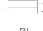
- a battery separator including a non-woven web is shown schematically in FIG. 1 .
- a battery separator 5 may include a non-woven web 6.
- a non-woven web 6 includes a plurality of glass fibers.
- the non-woven web may also include a plurality inorganic particles, such as silica particles.
- the battery separator may be a single layer (e.g., the separator does not include layer 7 FIG. 1 ).
- the battery separator may be formed of a single non-woven web.
- the battery separator may comprise multiple layers.
- the battery separator may include an optional layer 7 (e.g., additional layer), which may be adjacent the non-woven web (e.g., contacting one sides of the non-woven web).
- the multi-layer battery separator may include at least one non-woven web (e.g., at least two non-woven webs, at least three non-woven webs), with at least one non-woven including a plurality of inorganic particles, as described herein.
- one or more optional layers may be a non-woven web.
- optional/additional layers include fibrous webs such as non-woven webs comprising a plurality of glass fibers, which may also include a plurality of inorganic particles in some embodiments, but in other embodiments, may be substantially free of inorganic particles.
- fibrous webs such as non-woven webs comprising a plurality of glass fibers, which may also include a plurality of inorganic particles in some embodiments, but in other embodiments, may be substantially free of inorganic particles.
- Other types of layers are also possible.
- a layer when referred to as being "adjacent" another layer, it can be directly adjacent to the layer, or an intervening layer also may be present.
- a layer that is "directly adjacent" another layer means that no intervening layer is present.
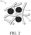
- Non-limiting examples of a non-woven web including inorganic particles is shown in FIGs. 2A-2C .
- examples of inorganic particles are provided below.
- a non-woven web 10 shown in cross-section, may include a plurality of fibers 15 (e.g., glass fibers, glass fibers and synthetic fibers).
- non-woven web 10 may also comprise a plurality of inorganic particles 18 (e.g., sulfuric acid-resistant inorganic particles).
- the non-woven web may comprise inorganic particles.
- inorganic particles in the non-woven web may result in an increase in the surface area of the non-woven web without significantly altering the volume porosity of the non-woven web.
- the resulting non-woven web may have improved wettability to electrolyte and may absorb more electrolyte compared to a similar non-woven web that lacks inorganic particles (all other factors being equal). Consequently, a non-woven web including inorganic particles may have a reduced acid stratification distance compared to a similar non-woven web that lacks inorganic particles (all other factors being equal).
- the inorganic particles may serve to reduce the pore size and/or the variation in pore size of the non-woven web.
- Non-limiting examples of inorganic particles include silica (e.g., fumed, precipitated, colloid), clay, talc, diatoms (e.g., diatomaceous earth), zeolites, and combinations thereof.
- the inorganic particles e.g., silica
- the inorganic particles are ground, fused, and/or agglomerated.
- the inorganic particles are substantially non-porous.
- the inorganic particles may be porous in some instances.
- a suitable inorganic particle may be resistant to sulfuric acid and/or may have a suitable surface area, as described in more detail below. Additionally, the inorganic particles may be chemically inert and thermally stable.
- the weight percentage of inorganic particles in the non-woven web and/or battery separator may be greater than or equal to about 3 wt.%, greater than or equal to about 5 wt.%, greater than or equal to about 7 wt.%, greater than or equal to about 10 wt.%, greater than or equal to about 15 wt.%, greater than or equal to about 20 wt.%, or greater than or equal to about 25 wt.%.
- the weight percentage of inorganic particles in the non-woven web and/or battery separator may be less than or equal to about 30 wt.%, less than or equal to about 25 wt.%, less than or equal to about 20 wt.%, less than or equal to about 15 wt.%, less than or equal to about 10 wt.%, less than or equal to about 7 wt.%, or less than or equal to about 5 wt.%. Combinations of the above-referenced ranges are also possible (e.g., greater than or equal to about 3 wt.% and less than about 30 wt.%, greater than or equal to about 5 wt.% and less than about 15 wt.%). Other ranges are also possible.
- the weight percentage of inorganic particles in the entire non-woven web and/or battery separator is based on the dry solids and can be determined prior to forming the non-woven web.
- the inorganic particles may have a relatively high surface area.
- inorganic particles with a high surface area may resist stratification, or layering of acid, which may occur during charge of the battery.
- the inorganic particles included in a non-woven web and/or separator described herein may be chosen to have a particular range of average surface area.
- the average surface area of the inorganic particles may be, for example, greater than or equal to about 100 m 2 /g, greater than or equal to about 200 m 2 /g, greater than or equal to about 300 m 2 /g, greater than or equal to about 400 m 2 /g, greater than or equal to about 500 m 2 /g, greater than or equal to about 600 m 2 /g, greater than or equal to about 700 m 2 /g, greater than or equal to about 750 m 2 /g, or greater than or equal to about 800 m 2 /g.
- the average surface area of the inorganic particles may be less than or equal to about 850 m 2 /g, less than or equal to about 750 m 2 /g, less than or equal to about 700 m 2 /g, less than or equal to about 600 m 2 /g, less than or equal to about 500 m 2 /g, less than or equal to about 400 m 2 /g, less than or equal to about 300 m 2 /g, or less than or equal to about 200 m 2 /g.
- the average particle size (e.g., average diameter, or average largest cross-sectional dimension) of the inorganic particles included in a non-woven web and/or separator described herein may be, for example, greater than about 0.01 microns, greater than or equal to about 0.05 microns, greater than or equal to about 0.1 microns, greater than or equal to about 0.5 microns, greater than or equal to about 1 micron, greater than or equal to about 2 microns, greater than or equal to about 4 microns, greater than or equal to about 6 microns, greater than or equal to about 8 microns, greater than or equal to about 10 microns, greater than or equal to about 12 microns, greater than or equal to about 14 microns, greater than or equal to about 16 microns, or greater than or equal to about 18 microns.
- the particles may have an average particle size of, for example, less than or equal to about 20 microns, less than or equal to about 18 microns, less than or equal to about 16 microns, less than or equal to about 14 microns, less than or equal to about 12 microns, less than or equal to about 10 microns, less than or equal to about 8 microns, less than or equal to about 6 microns, less than or equal to about 4 microns, less than or equal to about 2 microns, less than or equal to about 1 micron, less than or equal to about 0.5 microns, less than or equal to about 0.1 microns, or less than or equal to about 0.05 microns.
- the inorganic particles included in a nonwoven web and/or battery separator may be resistant to sulfuric acid.
- particles that are resistant to sulfuric acid refer to inorganic particles that have an acid weight loss of less than 20% (e.g., less than 15%, less than 10%, less than 5%) of the total weight of the particles after a three-hour reflux in 1.260 SG sulfuric acid using the BCIS-03A Mar 2010 method 13.
- inorganic particles having a total weight loss of less than 20%, less than 15%, less than 10%, or less than 5% are used in a non-woven web and/or battery separator described herein.
- any suitable process may be used to add the inorganic particles to the non-woven web and/or battery separator.
- the inorganic particles are added with the fibers in the fiber slurry (e.g., forming a wet stock which may be subsequently dried) during formation of the non-woven web.
- a non-woven web may include glass fibers (e.g., microglass fibers, chopped strand glass fibers, or a combination thereof).
- Glass fibers e.g., microglass fibers, chopped strand glass fibers, or a combination thereof.
- Microglass fibers and chopped strand glass fibers are known to those of ordinary skill in the art. One of ordinary skill in the art is able to determine whether a glass fiber is microglass or chopped strand by observation (e.g., optical microscopy, electron microscopy). Microglass fibers may also have chemical differences from chopped strand glass fibers. In some cases, though not required, chopped strand glass fibers may contain a greater content of calcium or sodium than microglass fibers. For example, chopped strand glass fibers may be close to alkali free with high calcium oxide and alumina content.
- Microglass fibers may contain 10-15% alkali (e.g., sodium, magnesium oxides) and have relatively lower melting and processing temperatures.
- alkali e.g., sodium, magnesium oxides
- the terms refer to the technique(s) used to manufacture the glass fibers. Such techniques impart the glass fibers with certain characteristics.
- chopped strand glass fibers are drawn from bushing tips and cut into fibers in a process similar to textile production. Chopped strand glass fibers are produced in a more controlled manner than microglass fibers, and as a result, chopped strand glass fibers will generally have less variation in fiber diameter and length than microglass fibers.
- Microglass fibers are drawn from bushing tips and further subjected to flame blowing or rotary spinning processes. In some cases, fine microglass fibers may be made using a remelting process. In this respect, microglass fibers may be fine or coarse. As used herein, fine microglass fibers are less than or equal to 1 micron in diameter and coarse microglass fibers are greater than or equal to 1 micron in
- the microglass fibers may have small diameters.
- the average diameter of the microglass fibers may be less than or equal to about 10 microns, less than or equal to about 9 microns, less than or equal to about 7 microns, less than or equal to about 5 microns, less than or equal to about 3 microns, or less than or equal to about 1 micron.
- the microglass fibers may have an average fiber diameter of greater than or equal to about 0.1 microns, greater than or equal to about 0.3 microns, greater than or equal to about 1 micron, greater than or equal to about 3 microns, or greater than or equal to about 7 microns.
- microglass fibers are generally log-normal. However, it can be appreciated that microglass fibers may be provided in any other appropriate average diameter distribution (e.g., Gaussian distribution).
- the average length of microglass fibers may be less than or equal to about 10 mm, less than or equal to about 8 mm, less than or equal to about 6 mm, less than or equal to about 5 mm, less than or equal to about 4 mm, less than or equal to about 3 mm, or less than or equal to about 2 mm. In certain embodiments, the average length of microglass fibers may be greater than or equal to about 1 mm, greater than or equal to about 2 mm, greater than or equal to about 4 mm, greater than or equal to about 5 mm, greater than equal to about 6 mm, or greater than or equal to about 8 mm. Combinations of the above referenced ranges are also possible (e.g., microglass fibers having an average length of greater than or equal to about 4 mm and less than about 6 mm). Other ranges are also possible.
- chopped strand glass fibers may have an average fiber diameter that is greater than the diameter of the microglass fibers.
- the average diameter of the chopped strand glass fibers may be greater than or equal to about 5 microns, greater than or equal to about 7 microns, greater than or equal to about 9 microns, greater than or equal to about 11 microns, or greater than or equal to about 20 microns.
- the chopped strand glass fibers may have an average fiber diameter of less than or equal to about 30 microns, less than or equal to about 25 microns, less than or equal to about 15 microns, less than or equal to about 12 microns, or less than or equal to about 10 microns.
- chopped strand diameters tend to follow a normal distribution. Though, it can be appreciated that chopped strand glass fibers may be provided in any appropriate average diameter distribution (e.g., Gaussian distribution).
- chopped strand glass fibers may have a length in the range of between about 3 mm and about 25 mm (e.g., about 6 mm, or about 12 mm). In some embodiments, the average length of chopped strand glass fibers may be less than or equal to about 25 mm, less than or equal to about 20 mm, less than or equal to about 15 mm, less than or equal to about 12 mm, less than or equal to about 10 mm, less than or equal to about 7 mm, or less than or equal to about 5 mm.
- the average length of chopped strand glass fibers may be greater than or equal to about 3 mm, greater than or equal to about 5 mm, greater than or equal to about 10 mm, greater than or equal to about 12 mm, greater than equal to about 15 mm, or greater than or equal to about 20 mm. Combinations of the above referenced ranges are also possible (e.g., chopped strand glass fibers having an average length of greater than or equal to about 3 mm and less than about 25 mm). Other ranges are also possible.
- microglass and/or chopped strand fibers may also have other dimensions.
- the average diameter of the glass fibers (e.g., regardless of whether the glass fibers are microglass, chopped strand, or another type) in the non-woven web may be greater than or equal to about 1.5 microns, greater than or equal to about 2 microns, greater than or equal to about 2.5 microns, greater than or equal to about 3 microns, greater than or equal to about 4.5 microns, greater than or equal to about 5 microns, greater than or equal to about 6 microns, greater than or equal to about 7 microns, or greater than or equal to about 9 microns.
- the average diameter of the glass fibers in the non-woven web may have an average fiber diameter of less than or equal to about 10 microns, less than or equal to about 9 microns, less than or equal to about 7 microns, less than or equal to about 6 microns, less than or equal to about 5 microns, less than or equal to about 4.5 microns, less than or equal to about 3 microns, less than or equal to about 2.5 microns, or less than or equal to about 2 microns.
- Combinations of the above-referenced ranges are also possible (e.g., greater than or equal to about 1.5 microns and less than or equal to about 10 microns, greater than or equal to about 2 microns and less than or equal to about 9 microns, greater than or equal to about 2 microns and less than or equal to about 5 microns, greater than or equal to about 2.5 microns and less than or equal to about 4.5 microns).
- the average length of the glass fibers in the non-woven web may be less than or equal to about 25 mm, less than or equal to about 20 mm, less than or equal to about 15 mm, less than or equal to about 12 mm, less than or equal to about 10 mm, less than or equal to about 8 mm, less than or equal to about 5 mm, less than or equal to about 3 mm, or less than or equal to about 1 mm.
- the average length of the glass fibers in the non-woven web may be greater than or equal to about 0.05 mm, greater than or equal to about 0.1 mm, greater than or equal to about 0.3 mm, greater than or equal to about 0.5 mm, greater than equal to about 1 mm, greater than or equal to about 5 mm, greater than equal to about 10 mm, greater than or equal to about 15 mm, or greater than equal to about 20 mm.
- Combinations of the above referenced ranges are also possible (e.g., greater than or equal to about 1 mm and less than about 25 mm, greater than or equal to about 0.3 mm and less than about 20 mm, greater than or equal to about 0.1 mm and less than about 12 mm, greater than or equal to about 0.2 mm and less than about 6 mm, greater than or equal to about 0.5 mm and less than about 3 mm). Other ranges are also possible.
- a non-woven web may include a suitable percentage of glass fibers (e.g., regardless of whether the glass fibers are microglass, chopped strand, or another type).
- the weight percentage of glass fibers in the non-woven web may be greater than or equal to about 50 wt.%, greater than or equal to about 60 wt.%, greater than or equal to about 70 wt.%, greater than or equal to about 80 wt.%, greater than or equal to about 90 wt.%, or greater than or equal to about 95 wt.%.
- the weight percentage of the glass fibers in the non-woven web may be less than or equal to about 97 wt.%, less than or equal to about 95 wt.%, less than or equal to about 90 wt.%, less than or equal to about 80 wt.%, less than or equal to about 70 wt.%, or less than or equal to about 60 wt.%.
- a non-woven web includes the above-noted ranges of glass fibers with respect to the total weight of fibers in the non-woven web and/or the battery separator.
- the non-woven web comprises between about 0 wt.% and about 30 wt.% chopped strand glass fibers and the remainder comprising microglass fibers.
- the non-woven web comprises greater than or equal to about 0 wt.%, greater than or equal to about 5 wt.%, greater than or equal to about 10 wt.%, greater than or equal to about 15 wt.%, greater than or equal to about 20 wt.%, or greater than or equal to about 25 wt.% chopped strand glass fibers and the remainder comprising microglass fibers.
- the non-woven web comprises less than or equal to about 30 wt.%, less than or equal to about 25 wt.%, less than or equal to about 20 wt.%, less than or equal to about 15 wt.%, less than or equal to about 10 wt.%, or less than or equal to about 5 wt.% chopped strand glass fibers and the remainder comprising microglass fibers. Combinations of the above-referenced ranges are also possible (e.g., greater than about 0 wt.% and less than or equal to about 30 wt.% chopped strand glass fibers, greater than about 5 wt.% and less than or equal to about 10 wt.% chopped strand glass fibers). Other ranges are also possible.
- a non-woven web includes the above-noted ranges of chopped strand glass fibers with respect to the total weight of fibers in the non-woven web and/or the battery separator.
- a non-woven web described herein includes one or more synthetic fibers.
- Synthetic fibers may include any suitable type of synthetic polymer. Examples of suitable synthetic fibers include polyester (e.g., polyethylene terephthalate), polyaramid, polyimide, polyolefin (e.g., polyethylene), polypropylene, Kevlar, nomex, halogenated polymers, acrylics, polyphenylene oxide, polyphenylene sulfide, and combinations thereof.
- the synthetic fibers are organic polymer fibers. Synthetic fibers may also include multi-component fibers (i.e., fibers having multiple compositions such as bi-component fibers).
- the non-woven web may also include combinations of more than one type of composition of synthetic fiber. It should be understood that other compositions of synthetic fiber types may also be used.
- synthetic fibers may be binder fibers, as described in more detail below.
- Non-woven webs including combinations of different types of synthetic fibers are also possible.
- a non-woven web may include a suitable percentage of synthetic fibers.
- the weight percentage of synthetic fibers in the non-woven web may be 0%, greater than or equal to about 1 wt.%, greater than or equal to about 4 wt.%, greater than or equal to about 5 wt.%, greater than or equal to about 10 wt.%, or greater than or equal to about 15 wt.%.
- the weight percentage of the synthetic fibers in the non-woven web may be less than or equal to about 20 wt.%, less than or equal to about 10 wt.%, less than or equal to about 5 wt.%, or less than or equal to about 4 wt.%.
- a non-woven web includes the above-noted ranges of synthetic fibers with respect to the total weight of fibers in the non-woven web and/or the battery separator.
- synthetic fibers may have any suitable dimensions.
- the synthetic fibers may have an average diameter of greater than or equal to about 0.5 micron, greater than or equal to about 1 micron, greater than or equal to about 2 microns, greater than or equal to about 4 microns, greater than or equal to about 6 microns, greater than or equal to about 8 microns, greater than or equal to about 10 microns, greater than or equal to about 12 microns, greater than or equal to about 15 microns, greater than or equal to about 20 microns, greater than or equal to about 30 microns, or greater than or equal to about 40 microns.
- the synthetic fibers may have an average diameter of less than or equal to about 50 microns, less than or equal to about 40 microns, less than or equal to about 30 microns, less than or equal to about 20 microns, less than or equal to about 15 microns, less than or equal to about 12 microns, less than or equal to about 10 microns, than or equal to about 8 microns, less than or equal to about 6 microns, less than equal to about 4 microns, or less than or equal to about 2 microns. Combinations of the above referenced ranges are also possible (e.g., greater than or equal to about 0.5 microns and less than about 50 microns, greater than or equal to about 2 microns and less than about 20 microns). Other ranges are also possible.
- synthetic fibers may have an average length of greater than or equal to about 0.25 mm, greater than or equal to about 0.5 mm, greater than or equal to about 1 mm, greater than or equal to about 3 mm, greater than or equal to about 5 mm, greater than or equal to about 10 mm, greater than or equal to about 25 mm, or greater than or equal to about 50 mm.
- synthetic fibers may have an average length of less than or equal to about 50 mm, less than or equal to about 25 mm, less than or equal to about 20 mm, less than or equal to about 15 mm, less than or equal to about 12 mm, less than or equal to about 10 mm, less than or equal to about 9 mm, less than or equal to about 6 mm, less than or equal to about 4 mm, less than or equal to about 2 mm, or less than or equal to about 1 mm. Combinations of the above-referenced ranges are also possible (e.g., greater than or equal to about 1 mm and less than or equal to about 12 mm, greater than or equal to about 3 mm and less than or equal to about 15 mm). Other values of average fiber length are also possible.
- the synthetic fibers may be binder fibers.
- the binder fibers may be mono-component (i.e., having a single composition) or multi-component (i.e., having multiple compositions such as a bi-component fiber).
- the non-woven web may include a suitable percentage of mono-component fibers and/or multi-component fibers. In some embodiments, all of the synthetic fibers are mono-component fibers. In some embodiments, at least a portion of the synthetic fibers are multi-component fibers. In some embodiments, the non-woven web may comprise a residue from a binder fiber.
- a multi-component fiber is a bi-component fiber which includes a first material and a second material that is different from the first material.
- the different components of a multi-component fiber may exhibit a variety of spatial arrangements.
- multi-component fibers may be arranged in a core-sheath configuration (e.g., a first material may be a sheath material that surrounds a second material which is a core material), a side by side configuration (e.g., a first material may be arranged adjacent to a second material), a segmented pie arrangement (e.g., different materials may be arranged adjacent to one another in a wedged configuration), a tri-lobal arrangement (e.g., a tip of a lobe may have a material different from the lobe) and an arrangement of localized regions of one component in a different component (e.g., "islands in sea").
- a core-sheath configuration e.g., a first material may be a
- a multi-component fiber such as a bi-component fiber, may include a sheath of a first material that surrounds a core comprising a second material.
- the melting point of the first material may be lower than the melting point of the second material. Accordingly, at a suitable step during manufacture of a non-woven web (e.g., drying), the first material comprising the sheath may be melted (e.g., may exhibit a phase change) while the second material comprising the core remains unaltered (e.g., may exhibit no phase change).
- an outer sheath portion of a multi-component fiber may have a melting temperature between about 50 °C and about 200 °C (e.g., 180 °C) and an inner core of the multi-component fiber may have a melting temperature above 200 °C.
- a temperature during drying e.g., at 180 °C
- the outer sheath of the fiber may melt while the core of the fiber does not melt.
- suitable multi-component fibers include polyolefin (e.g., polyethylene / PET, coPET (e.g., melt amorphous, melt crystalline) / PET, PBT / PET, and polyethylene / polypropylene.
- polyolefin e.g., polyethylene / PET, coPET (e.g., melt amorphous, melt crystalline) / PET, PBT / PET, and polyethylene / polypropylene.
- the convention is to list the material having the lower melting temperature (e.g., first material) separated from the material having the higher melting temperature (e.g., second material) with a "/”.
- the binder fiber may include a vinyl compounds (e.g., polyvinyl alcohol).
- the weight percentage of multi-component fibers (e.g., bi-component fibers) in the non-woven web may be 0%, greater than or equal to about 1 wt.%, greater than or equal to about 4 wt.%, greater than or equal to about 5 wt.%, greater than or equal to about 10 wt.%, or greater than or equal to about 15 wt.% In some embodiments, the weight percentage of the multi-component fibers (e.g., bi-component fibers) in the non-woven web may be less than or equal to about 20 wt.%, less than or equal to about 10 wt.%, less than or equal to about 5 wt.%, or less than or equal to about 4 wt.%.
- a non-woven web includes the above-noted ranges of multi-component fibers (e.g., bi-component fibers) with respect to the total weight of fibers in the non-woven web and/or the battery separator.
- multi-component fibers e.g., bi-component fibers
- the non-woven web may include one or more additional types of fibers.
- the one or more additional fibers may include natural fibers (e.g., cellulose), carbon fibers, nanofibers, and/or fibrillated fibers.
- the weight percentage of the one or more additional fibers in the non-woven web may be 0 wt.%, greater than or equal to about 0.5 wt.%, greater than or equal to about 1 wt.%, greater than or equal to about 2 wt.%, greater than or equal to about 5 wt.%, or greater than or equal to about 7 wt.%.
- the weight percentage of the one or more additional fibers in the non-woven web may be less than or equal to about 10 wt.%, less than or equal to about 7 wt.%, less than or equal to about 5 wt.%, less than or equal to about 2 wt.%, less than or equal to about 1 wt.%, or less than or equal to about 0.5 wt.%. Combinations of the above-referenced ranges are also possible (e.g., greater than or equal to about 0.5 wt.% and less than or equal to about 10 wt.%, greater than or equal to about 1 wt.% and less than or equal to about 5 wt.%)
- the non-woven web/separator may include a retention aid.
- the retention aid may aid in retaining the inorganic particles in the non-woven web.
- Various types of retention aids can be used.
- the retention aid may be cationic, anionic, or non-ionic.
- Non-limiting examples of retention aids include colloidal silica, aluminum chloride, sodium aluminate, polyaluminum sulfate, polyaluminum chloride, cationic or anionic-modified polyacrylamides, guar gum (e.g., amine-treated cationic guar gum), starches (e.g., anionic oxidized starches), and non-ionic polymeric materials such as polyacrylamide and polyethylene oxide.
- Other retention aids are also possible.
- the amount of the retention aid present in the non-woven web/separator may be, for example, at least about 0.02 wt%, at least about 0.04 wt%, at least about 0.05 wt%, at least about 0.1 wt%, at least about 0.15 wt%, at least about 0.2 wt%, at least about 0.3 wt%, at least about 0.4 wt%, or at least about 0.5 wt% of the total weight of the non-woven web/separator.
- the amount of retention aid present in the non-woven web/separator may be less than or equal to about 1 wt%, less than or equal to about 0.5 wt%, less than or equal to about 0.4 wt%, less than or equal to about 0.3 wt%, less than or equal to about 0.2 wt%, less than or equal to about 0.15 wt%, less than or equal to about 0.1 wt%, less than or equal to about 0.05 wt%, or less than or equal to about 0.05 wt% of the total weight of the non-woven web/separator. Combinations of the above referenced ranges are also possible (e.g., between about 0.02 wt% and about 0.5 wt%). Other ranges are also possible.
- the weight percentage of retention aid in the non-woven web and/or battery separator is based on the dry solids.
- the retention aid may be added to the fiber web in any suitable manner.
- the retention aid is added to the fiber slurry during formation of the non-woven web.
- one or more of the above-noted ranges of retention aid may be added to a fiber slurry during formation of the non-woven web, and the weight percentages may be based on the solids present in the slurry.
- a non-woven web (e.g., a non-woven web comprising a plurality of glass fibers and a plurality of inorganic particles) described herein has a desirable acid filling time (e.g., the time for filling the battery separator with an acid electrolyte), as described herein.
- the acid filling time is less than or equal to about 200 seconds, less than or equal to about 150 seconds, less than or equal to about 100 seconds, less than or equal to about 75 seconds, or less than or equal to about 50 seconds.
- the acid filling time is greater than or equal to about 30 seconds, greater than or equal to about 50 seconds, greater than or equal to about 75 seconds, greater than or equal to about 100 seconds, or greater than or equal to about 150 seconds. Combinations of the above-referenced ranges are also possible (e.g., greater than or equal to about 30 seconds and less than or equal to about 200 seconds, greater than or equal to about 50 seconds and less than or equal to about 150 seconds). Other ranges are also possible.
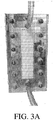
- acid filling time is measured by placing a 6.0 inch (measured in the machine direction (MD)) x 1.9 inch sample non-woven web/separator cut in the machine direction upright between two plates (e.g., polycarbonate plates) and surrounded by a gasket (e.g., so that acid does not go beyond the sides of the non-woven web).
- An exemplary test apparatus is shown in FIG. 3A .
- An inlet to the space between the plates i.e., within the area defined by the gasket and where the sample is present
- the plates are separated by a distance such that the separator sample has an average density of about 200 g/m 2 /mm.
- the plates may be separated by first determining the thickness of the separator required to obtain an average density of about 200 g/m 2 /mm, and placing shims of specific thickness(es) between the plates to maintain that thickness.
- Acid is filled into the inlet such that the acid contacts the top edge of the sample.
- Vacuum 530 mm Hg of pressure
- the acid filling time is determined by the amount of time required for the acid to travel 6 inches vertically through the sample. The timing is stopped at the moment the acid is seen exiting the bottom of the upright sample.
- the test is perfomed at ambient pressure and at a temperature of between about 15-25 degrees Celsius.
- a non-woven web e.g., a non-woven web comprising a plurality of glass fibers and a plurality of inorganic particles
- Acid absorption capacity is measured as the weight of acid in grams absorbed by the non-woven web per weight of non-woven web.
- the acid absorption capacity of the non-woven web is greater than or equal to about 7 g acid /g non-woven web, greater than or equal to about 7.5 g acid /g non-woven web, greater than or equal to about 8 g acid /g non-woven web, greater than or equal to about 8.5 g acid /g non-woven web, greater than or equal to about 9 g acid /g non-woven web, or greater than or equal to about 9.5 g acid /g non-woven web.
- the acid absorption capacity of the non-woven web is less than or equal to about 10 g acid/g non-woven web, less than or equal to about 9.5 g acid/g non-woven web, less than or equal to about 9 g acid/g non-woven web, less than or equal to about 8.5 g acid/g non-woven web, less than or equal to about 8 g acid/g non-woven web, or less than or equal to about 7.5 g acid/g non-woven web.
- acid absorption capacity is measured by preparing a sample of non-woven web, measuring the dry weight of the non-woven web, and submerging the non-woven web into an acid electrolyte (a sulfuric acid solution having a specific gravity of 1.28 g/cm 3 ) (e.g., for about 15 minutes) such that the electrolyte is absorbed.
- acid electrolyte a sulfuric acid solution having a specific gravity of 1.28 g/cm 3
- the sample is removed from the acid electrolyte and excess electrolyte is removed by hanging the sample with tweezers and allowing the excess acid to drip from the sample.
- the non-woven web is weighed after the electrolyte no longer drips from the web for 1 minute.
- the acid absorption capacity is the difference in the wet weight (e.g., the non-woven web and the absorbed acid electrolyte) and the dry weight of the non-woven web, divided by the dry weight of the non-woven web.
- the test is perfomed at ambient pressure and at a temperature of between about 15-25 degrees Celsius.
- a non-woven web (e.g., a non-woven web comprising a plurality of glass fibers and a plurality of inorganic particles) described herein has a particular acid stratification distance.
- the acid stratification distance is a measure of the distance of which the acid electrolyte displaces an sulfuric acid solution having a specific gravity of 1.1 g/cm 3 in a non-woven web within 60 min (e.g., while under compression).
- the acid stratification distance of the non-woven web is greater than or equal to about 0.5 cm, greater than or equal to about 1 cm, greater than or equal to about 2 cm, greater than or equal to about 3 cm, or greater than or equal to about 4 cm.
- the acid stratification distance of the non-woven web is less than or equal to about 5 cm, less than or equal to about 4 cm, less than or equal to about 3 cm, less than or equal to about 2 cm, or less than or equal to about 1 cm. Combinations of the above-referenced ranges are also possible (e.g., greater than or equal to about 0.5 cm and less than or equal to about 5 cm, greater than or equal to about 1 cm and less than or equal to about 3 cm). Other ranges are also possible.
- acid stratification distance is measured by first immersing a 8.5 inches (measured in the MD) x 1.5 inches sample of non-woven web/separator in an sulfuric acid solution having a specific gravity of 1.1 g/cm 3 for about one minute, e.g., until the non-woven web is saturated with the acid. Then the saturated sample is placed upright, vertically-oriented, between two plates (e.g., polycarbonate plates) and surrounded by a gasket (e.g., such that acid does not go beyond the sides of the sample), such that the top surface of the sample is accessible at the top of the plates.
- An exemplary test apparatus is shown in FIG. 3B .
- the plates are separated at a distance such that the separator sample has an average density of about 240 g/m 2 /mm.
- the plates may be separated by first determining the thickness of the separator required to obtain an average density of about 240 g/m 2 /mm, and placing shims of specific thickness(es) between the plates to maintain that thickness.
- a volume of 10-25 mL of an acid electrolyte (sulfuric acid having a specific gravity of about 1.28 g/cm 3 containing a soluble dye) is introduced into the accessible region at the top of the non-woven web between the plates until it just contacts the top edge of the sample.
- the distance the acid electrolyte travels downward after 60 minutes (displacing the initial acid within the non-woven web) is determined (i.e. the acid stratification distance). If there is variation in the distance the acid electrolyte travels (e.g., variation across the width of the sample), the middle point between the highest and lowest distances is used to calcuate the acid stratification distance.
- the test is perfomed at ambient pressure and at a temperature of between about 15-25 degrees Celsius.
- FIG. 4 shows a cross-section of an exemplary battery arrangement.
- FIG. 4 shows a cross-section of a battery arrangement comprising a planar battery separator 70 (e.g., including a non-woven web described herein) positioned between and in direct contact with a negative electrode 75 and a positive electrode 80.
- a planar battery separator 70 e.g., including a non-woven web described herein
- the entire surface area of the negative electrode and the positive electrode are in contact with the planar battery separator.
- the battery separator including a non-woven web comprising a plurality of inorganic may have desirable structural properties.
- the basis weight of one or more layers of the battery separator may range from between about 25 g/m 2 and about 500 g/m 2 .
- the basis weight of one or more layers of the battery separator may be greater than or equal to about 25 g/m 2 , greater than or equal to about 40 g/m 2 , greater than or equal to about 60 g/m 2 , greater than or equal to about 80 g/m 2 , greater than or equal to about 100 g/m 2 , greater than or equal to about 150 g/m 2 , greater than or equal to about 200 g/m 2 , greater than or equal to about 250 g/m 2 , greater than or equal to about 300 g/m 2 , greater than or equal to about 350 g/m 2 or greater than or equal to about 400 g/m 2 .
- the basis weight of one or more layers of the battery separator may be less than or equal to about 500 g/m 2 , less than or equal to about 430 g/m 2 , less than or equal to about 400 g/m 2 , less than or equal to about 350 g/m 2 , less than or equal to about 300 g/m 2 , less than or equal to about 250 g/m 2 , less than or equal to about 200 g/m 2 , less than or equal to about 150 g/m 2 , less than or equal to about 100 g/m 2 , less than or equal to about 75 g/m 2 , or less than or equal to about 50 g/m 2 .
- the basis weight of the non-woven web and/or battery separator is measured according to the BCIS-03A, Sept -09, Method 3.
- the specific surface area of one or more layers of the battery separator may range from between about 1 m 2 /g and about 100 m 2 /g.
- the specific surface area of one or more layers of the battery separator may be greater than or equal to about 1 m 2 /g, greater than or equal to about 2 m 2 /g, greater than or equal to about 5 m 2 /g, greater than or equal to about 10 m 2 /g, greater than or equal to about 20 m 2 /g, greater than or equal to about 50 m 2 /g, or greater than or equal to about 75 m 2 /g.
- the specific surface area of one or more layers of the battery separator may be less than or equal to about 100 m 2 /g, less than or equal to about 75 m 2 /g, less than or equal to about 50 m 2 /g, less than or equal to about 20 m 2 /g, less than or equal to about 10 m 2 /g, less than or equal to about 5 m 2 /g, or less than or equal to about 2 m 2 /g.
- Thickness is determined according to BCIS 03-A Sept-09, Method 10 using 10 kPa pressure.
- the thickness of one or more layers of the battery separator may be between about 0.05 mm and about 5 mm.
- the thickness of the non-woven web and/or battery separator may be greater than or equal to about 0.05 mm, greater than or equal to about 0.1 mm, greater than or equal to about 0.2 mm, greater than or equal to about 0.3 mm, greater than or equal to about 0.5 mm, greater than or equal to about 0.8 mm, greater than or equal to about 1 mm, greater than or equal to about 1.2 mm, greater than or equal to about 1.5 mm, greater than or equal to about 1.8 mm, greater than or equal to about 2 mm, greater than or equal to about 2.5 mm, greater than or equal to about 3 mm, greater than or equal to about 3.5 mm, greater than or equal to about 4 mm, or greater than or equal to about 4.5 mm.
- the thickness of one or more layers of the battery separator may be less than or equal to about 5 mm, less than or equal to about 4.5 mm, less than or equal to about 4 mm, less than or equal to about 3.5 mm, less than or equal to about 3 mm, less than or equal to about 2.5 mm, less than or equal to about 2.0 mm, less than or equal to about 1.8 mm, less than or equal to about 1.5 mm, less than or equal to about 1.2 mm, less than or equal to about 1 mm, less than or equal to about 0.8 mm, less than or equal to about 0.6 mm, less than or equal to about 0.4 mm, or less than or equal to about 0.2 mm. Combinations of the above-referenced ranges are also possible (e.g., greater than about 0.05 mm and less than or equal to about 5 mm, greater than about 0.1 mm and less than or equal to about 4 mm). Other
- the thickness of one or more layers of the battery separator may vary, for example, between about 0.05 mm and about 30 mm.
- the thickness of the non-woven web and/or battery separator may be greater than or equal to about 0.05 mm, greater than or equal to about 0.1 mm, greater than or equal to about 0.5 mm, greater than or equal to about 1 mm, greater than or equal to about 2 mm, greater than or equal to about 3 mm, greater than or equal to about 5 mm, greater than or equal to about 8 mm, greater than or equal to about 10 mm, greater than or equal to about 12 mm, greater than or equal to about 15 mm, greater than or equal to about 20 mm, or greater than or equal to about 25 mm.
- the thickness of one or more layers of the battery separator may be less than or equal to about 30 mm, less than or equal to about 28 mm, less than or equal to about 25 mm, less than or equal to about 20 mm, less than or equal to about 18 mm, less than or equal to about 15 mm, less than or equal to about 12 mm, less than or equal to about 10 mm, less than or equal to about 8 mm, less than or equal to about 6 mm, less than or equal to about 3 mm, less than or equal to about 2 mm, less than or equal to about 1 mm, or less than or equal to about 0.5 mm.
- a non-woven web and/or battery separator described herein may have a density of, for example, between about 100 g/m 2 /mm and about 250 g/m 2 /mm.
- the density of one or more layers of the battery separator may be less than or equal to about less than or equal to 250 g/m/mm, less than or equal to about less than or equal to about 225 g/m 2 /mm, less than or equal to about 200 g/m 2 /mm, less than or equal to about 175 g/m 2 /mm, less than or equal to about 150 g/m 2 /mm, or less than or equal to about 125 g/m 2 /mm.
- the density of one or more layers of the battery separator may be greater than or equal to about 100 g/m 2 /mm, greater than or equal to about 150 g/m 2 /mm, or greater than or equal to about 200 g/m 2 /mm. Combinations of the above-referenced ranges are also possible (e.g., greater than or equal to about 100 g/m 2 /mm and less than or equal to about 250 g/m 2 /mm greater than or equal to about 125 g/m 2 /mm and less than or equal to about 200 g/m 2 /mm). Other ranges are also possible.
- the density of one or more layers of the battery separator is measured by dividing the basis weight determined according to BCIS-03A Sept-09, Method 3 of the non-woven web (and/or battery separator) by the thickness of the non-woven web (and/or battery separator) determined according to BCIS 03-A Sept-09, Method 10 under 10kPa.
- One or more layers of the battery separator may have a suitable largest pore size.
- the largest pore size of the fiber web may influence the acid filling times and/or acid stratification distances.
- the largest pore size of the non-woven web and/or battery separator may be less than or equal to about 25 microns, less than or equal to about 20 microns, less than or equal to about 18 microns, less than or equal to about 16 microns, less than or equal to about 14 microns, less than or equal to about 12 microns, or less than or equal to about 10 microns.
- the largest pore size may be greater than or equal to about 8 microns, greater than or equal to about 10 microns, greater than or equal to about 12 microns, greater than or equal to about 14 microns, or greater than or equal to about 16 microns. Combinations of the above-referenced ranges are also possible (e.g., greater than or equal to about 8 microns and less than or equal to about 18 microns, greater than or equal to about 10 microns and less than or equal to about 16 microns). Other values and ranges of largest pore size are also possible. Largest pore size, as determined herein, is measured using liquid porosimetry according to the standard BCIS-03A, Sept -09, Method 6.
- One or more layers of the battery separator may exhibit a suitable median pore size, e.g., for ionic conduction.
- the median pore size of the non-woven web and/or battery separator may be less than or equal to about 7 microns, less than or equal to about 6.5 microns, less than or equal to about 6 microns, less than or equal to about 5.5 microns, less than or equal to about 5 microns, less than or equal to about 4.5 microns, less than or equal to about 4 microns, less than or equal to about 3.5 microns, or less than or equal to about 3 microns.
- the median pore size may be greater than or equal to about 2.5 microns, greater than or equal to about 3 microns, greater than or equal to about 3.5 microns, greater than or equal to about 4 microns, greater than or equal to about 5 microns, or greater than or equal to about 6 microns. Combinations of the above-referenced ranges are also possible (e.g., greater than or equal to about 2.5 microns and less than or equal to about 4.5 microns, greater than or equal to about 3 microns and less than or equal to about 4 microns). Other values and ranges of median pore size are also possible. Median pore size, as determined herein, is measured according to the standard BCIS-03A, Sept -09, Method 6.
- a battery separator described herein comprising a non-woven web includes a plurality of inorganic particles (e.g., silica) and has a combination of largest pore size and median pore size within specific ranges.
- the battery separator and/or nonwoven web has a largest pore size ranging between about 8 microns and about 18 microns (e.g., a largest pore size ranging between about 10 microns and about 16 microns), and a median pore size ranging between about 2.5 microns and about 4.5 microns (e.g., a median pore size between about 3 microns and about 4 microns), although other ranges, such as those described above, are also possible.
- the battery separator and/or nonwoven web may exhibit a relatively fast acid filling time and/or a relatively low acid stratification distance (e.g., as compared to battery separator and/or a non-woven web having different largest and/or median pore sizes, and/or one that is substantially free of inorganic particles, all other factors being equal).
- the battery separator and/or nonwoven web may have an acid filling time of, for example, less than or equal to about 200 seconds and/or an acid stratification distance of, for example, less than or equal to about 5 cm.
- a non-woven web and/or battery separator described herein may have desirable mechanical strength characteristics.
- one or more layers of the battery separator e.g., the non-woven web and/or the overall battery separator
- the dry tensile strength in the machine direction may be less than or equal to about 20 lbs/in, less than or equal to about 15 lbs/in, less than or equal to about 12 lbs/in, less than or equal to about 10 lbs/in, less than or equal to about 5 lbs/in, less than or equal to about 2 lbs/in, less than or equal to about 1 lb/in, or less than or equal to about 0.5 lbs/in. Combinations of the above-referenced ranges are also possible (e.g., greater than or equal to about 0.5 lbs/in and less than or equal to about 20 lbs/in, greater than or equal to about 1 lb/in and less than or equal to about 15 lbs/in).
- the dry tensile strength in the machine direction may be determined using the standard BCIS 03B Rev Mar 2010 Method 4.
- the puncture strength (or puncture resistance) of a battery separator and/or a non-woven web described herein may be greater than or equal to about 1 N, greater than or equal to about 1.5 N, greater than or equal to about 2 N, greater than or equal to about 3 N, greater than or equal to about 5 N, greater than or equal to about 8 N, greater than or equal to about 10 N, greater than or equal to about 12N, or greater than or equal to about 15 N.
- the puncture strength (or puncture resistance) may be less than or equal to about 20 N, less than or equal to about 18 N, less than or equal to about 15 N, less than or equal to about 12 N, less than or equal to about 10 N, less than or equal to about 8 N, less than or equal to about 5 N, or less than or equal to about 3 N. Combinations of the above-referenced ranges are also possible (e.g., greater than or equal to about 1 N and less than or equal to about 20 N, greater than or equal to about 5 N and less than or equal to about 15 N).
- the puncture strength may be determined using protocol BCIS 03B Rev Mar 2010 Method 9.
- the pressure loss of a battery separator and/or a non-woven web described herein may be less than or equal to about 30%, less than or equal to about 25%, or less than or equal to about 20%. In certain embodiments, the pressure loss of a battery separator and/or a non-woven web described herein may be greater than or equal to about 15%, greater than or equal to about 20%, or greater than or equal to about 25%. Combinations of the above-referenced ranges are also possible (e.g., greater than or equal to about 15% and less than or equal to about 30%, greater than or equal to about 15% and less than or equal to about 25%). Other ranges are also possible.
- the pressure loss may be determined by placing a 10 cm x 10 cm non-woven web/separator sample into a plastic bag (e.g., 12 cm x 12 cm), and applying an in initial pressure of 30 kPa to the (dry) non-woven web/separator sample for 5 minutes (e.g., by placing the plastic bag between computer-operated plates and applying an external force (e.g., of 30 kPa) to the non-woven web/separator sample with the plates).
- the instrument is calibrated to take into account the thickness of the bag.
- About 20 mL of electrolyte (a sulfuric acid solution with a specific gravity of 1.28 g/cm 3 ) is added to the bag while the distance between the plates is maintained.
- the application of 30 kPa pressure to the sample is ceased, and while the distance between the plates is maintained, the pressure exerted by the plates on the sample after one hour is measured (e.g., by a load cell located behind one plate).
- the test is perfomed at ambient pressure and at a temperature of between about 15-25 degrees Celsius.
- the percent loss of pressure i.e. pressure loss
- the percent loss of pressure is calculated to be 100% x (30 - pressure in kPa recorded after 1 hr)/30.
- a non-woven web and/or battery separator described herein may have a tendency of losing thickness under cycles of compression pressure (e.g., compressed between 10 kPa and 50 kPa).
- the percent thickness loss is a general measure of elasticity of the non-woven web and/or battery separator, related to the ability of the non-woven web and/or battery separator to recover to its original thickness (or volume) after an applied pressure is removed. Generally, the lower the percent thickness loss, the more elastic the non-woven web and/or battery separator.
- the performance of the battery may be influenced by the elasticity of the non-woven web/separator, wherein the more elastic the non-woven web and/or battery separator (e.g., the lower the percent thickness loss), the better the performance of the battery comprising the non-woven web/separator.
- the percent thickness loss of a non-woven web and/or battery separator described herein at 10 kPa of pressure is less than or equal to about 30%, less than or equal to about 26.7%, less than or equal to about 23.4%, less than or equal to about 20.1%, less than or equal to about 16.8%, or less than or equal to about 13.5%.
- the percent thickness loss for the non-woven and/or battery separator at 10 kPa of pressure is greater than or equal to about 1%, greater than or equal to about 5%, greater than or equal to about 10%, greater than or equal to about 13.5%, greater than or equal to about 16.8%, greater than or equal to about 20.1%, greater than or equal to about 23.4%, or greater than or equal to about 26.7%
- Combinations of the above-referenced ranges are also possible (e.g., less than or equal to about 30% and greater than or equal to about 10% , less than equal to about 16.8% and greater than or equal to about 10%.). Other ranges are also possible.
- the percent thickness loss for a non-woven web and/or battery separator described herein at 50 kPa of pressure is less than or equal to about 15%, less than or equal to about 10%, less than or equal to about 7.8%, less than or equal to about 6.1%, less than or equal to about 4.5%, or less than or equal to about 2.8%. In some embodiments, the percent thickness loss of the non-woven and/or battery separator at 50 kPa of pressure is greater than or equal to about 1.2%, greater than or equal to about 2.8%, greater than or equal to about 4.5%, greater than or equal to about 6.1%, or greater than or equal to about 10%. Combinations of the above-referenced ranges are also possible (e.g., less than or equal to about 7.8% and greater than or equal to about 1.2%, greater than or equal to about 1.2% and less than or equal to about 6.1%). Other ranges are also possible.
- percent thickness loss of the non-woven web/separator is determined by placing a 10 cm x 10 cm sample non-woven web/separator into a plastic bag (e.g., 12 cm x 12 cm) and adding an acid electrolyte (sulfuric acid with a specific gravity of 1.28 g/cm 3 ) to the bag such that the non-woven web/separator is fully saturated (e.g., 15-30 mL).
- the instrument is calibrated to take into account the thickness of the bag.
- the plastic bag is compressed by a compression tester to about 10 kPa and then cycled between about 10 kPa and about 50 kPa for 20 cycles (wherein each cycle is 180 seconds).
- the percent change in thickness at a particular pressure is calculated by taking the difference of the thickness of the non-woven web/separator at the 20 th cycle at the particular pressure (e.g., 10 kPa or 50 kPa) and the thickness of the non-woven web/separator at the 1 st cycle at that particular pressure (e.g., 10 kPa or 50 kPa), and dividing the difference by the thickness of the non-woven web/separator at the 1 st cycle at the particular pressure (e.g., 10 kPa or 50 kPa), and multiplying by 100%.
- the test is perfomed at ambient pressure and at a temperature of between about 15-25 degrees Celsius.
- a separator described herein may be used in a battery (e.g., lead acid battery).
- the battery may comprise a negative plate, a positive plate, and a battery separator (e.g., including a non-woven web described herein) disposed between the negative and positive plates.
- Positive plates and negative plates can be formed of conventional lead acid battery plate materials.
- plates can include grids that include a conductive material, which can include, but is not limited to, lead, lead alloys, graphite, carbon, carbon foam, titanium, ceramics (such as Ebonex®), laminates and composite materials.
- the grids are typically pasted with active materials.
- the pasted grids are typically converted to positive and negative battery plates by a process called "formation.” Formation involves passing an electric current through an assembly of alternating positive and negative plates with separators between adjacent plates while the assembly is in a suitable electrolyte (e.g., to convert pasted oxide to active materials).
- positive plates may contain lead dioxide as the active material
- negative plates may contain lead as the active material
- Plates can also contain one or more reinforcing materials, such as chopped organic fibers (e.g., having an average length of 0.125 inch or more), chopped glass fibers, metal sulfate(s) (e.g., nickel sulfate, copper sulfate), red lead (e.g., a Pb 3 0 4 -containing material), litharge, paraffin oil, and/or expander(s).
- an expander contains barium sulfate, carbon black and lignin sulfonate as the primary components. The components of the expander(s) can be pre- mixed or not pre-mixed. Expanders are commercially available from, for example, Hammond Lead Products (Hammond, IN) and Atomized Products Group, Inc. (Garland, TX).
- an example of a commercially available expander is the Texex® expander (Atomized Products Group, Inc.).
- the expander(s), metal sulfate(s) and/or paraffin are present in positive plates, but not negative plates.
- positive plates and/or negative plates contain fibrous material or other glass compositions.
- a battery can be assembled using any desired technique.
- a separator may be cut into a sheet and may be placed between two plates, or the separator may be wrapped around the plates (e.g., positive electrode, negative electrode).
- the positive plates, negative plates and separators are then assembled in a case using conventional lead acid battery assembly methods.
- the battery separators may be used, in some embodiments, as a leaf separator, an envelope separator , and/or in a wound configuration.
- the separators are compressed after they are assembled in the case, i.e., the thickness of the separators are reduced after they are placed into the case.
- An electrolyte e.g., sulfuric acid
- the shapes (e.g., planar) of the battery separators described herein are non-limiting and the battery separators described herein may have any suitable shape.
- the electrolyte used with a battery separator described herein is sulfuric acid.
- the specific gravity of the sulfuric acid is between 1.21 g/cm 3 and 1.32 g/cm 3 (e.g., between 1.28 g/cm 3 and 1.31 g/cm 3 ).
- the specific gravity of the sulfuric acid is 1.26 g/cm 3 .
- the specific gravity of the sulfuric acid is about 1.3 g/cm 3 .
- the battery separators may be used in lead acid batteries including valve-regulated batteries (e.g., absorbent glass mat batteries).
- valve-regulated batteries e.g., absorbent glass mat batteries
- the internal environment is controlled by a valve for venting, the valve vents gas (e.g., hydrogen, oxygen) from the battery as pressure builds.
- gas e.g., hydrogen, oxygen
- the valve is a pressure relief valve, only opening when the internal battery pressure reaches a threshold. When the internal pressure in the battery is below this threshold the valve prevents either gas from escaping.
- the generated O 2 can diffuse from the positive electrode to the negative electrode and recombine with the H 2 to form water.
- oxygen and hydrogen The ability of oxygen and hydrogen to recombine in the battery governs several facets of the battery performance and safety. Pure oxygen and hydrogen are explosive gases, and thus recombination is important to avoid an explosive battery. A low level of recombination of oxygen and hydrogen also negatively affects the charge acceptance of the battery.
- the battery separators described herein may facilitate the recombination of oxygen and/or hydrogen, and thus increase the efficiency and performance of the battery.
- two or more layers of a web may be formed separately, and combined by any suitable method such as lamination, collation, or by use of adhesives.
- the two or more layers may be formed using different processes, or the same process.
- each of the layers may be independently formed by a wet laid process, a non-wet laid process, or any other suitable process.
- two or more layers may be formed by the same process. In some instances, the two or more layers may be formed simultaneously.
- layers may be adhered together by any suitable method. For instance, layers may be adhered by an adhesive and/or melt-bonded to one another on either side. Lamination and calendering processes may also be used. In some embodiments, an additional layer may be formed from any type of fiber or blend of fibers via an added headbox or a coater and appropriately adhered to another layer.
- one or more layer in the battery separator may be designed to be discrete from another layer. That is, the components (e.g., fibers) from one layer do not substantially intermingle (e.g., do not intermingle at all) with components (e.g., fibers) from another layer.
- the components (e.g., fibers) from one layer do not substantially intermingle (e.g., do not intermingle at all) with components (e.g., fibers) from another layer.
- fibers from non-woven web 6 do not substantially intermingle with fibers of optional layer 7.
- Discrete layers may be joined by any suitable process including, for example, lamination, thermo-dot bonding, calendering, ultrasonic processes, or by adhesives, as described in more detail below. It should be appreciated, however, that certain embodiments may include one or more layers that are not discrete with respect to one another.
- a battery separator may include any suitable number of layers, e.g., at least 2, at least 3, at least 4, at least 5, at least 6, at least 7 layers. In some embodiments, a battery separator may include up to 10 layers.
- Non-woven webs described herein may be produced using suitable processes, such as a wet laid process.
- a wet laid process involves mixing together fibers of one or more type; for example, glass fibers of one type may be mixed together with glass fibers of another type, and/or with fibers of a different type (e.g., synthetic fibers), to provide a fiber slurry.
- the slurry may be, for example, an aqueous-based slurry.
- fibers are optionally stored separately, or in combination, in various holding tanks prior to being mixed together.
- a first fiber may be mixed and pulped together in one container and a second fiber may be mixed and pulped in a separate container.
- the first fibers and the second fibers may subsequently be combined together into a single fibrous mixture.
- Appropriate fibers may be processed through a pulper before and/or after being mixed together.
- combinations of fibers are processed through a pulper and/or a holding tank prior to being mixed together.
- other components e.g., inorganic particles
- other combinations of fibers types may be used in fiber mixtures, such as the fiber types described herein.
- two or more layers are formed by a wet laid process.
- a first dispersion e.g., a pulp
- a solvent e.g., an aqueous solvent such as water
- a second dispersion e.g., another pulp
- a solvent e.g., an aqueous solvent such as water
- a battery separator may be a single layer of a non-woven web (e.g., formed by a wet laid process) in some embodiments without additional layers attached thereto.
- any suitable method for creating a fiber slurry may be used.
- further additives are added to the slurry to facilitate processing.
- the temperature may also be adjusted to a suitable range, for example, between 33 °F and 100 °F (e.g., between 50 °F and 85 °F). In some cases, the temperature of the slurry is maintained. In some instances, the temperature is not actively adjusted.
- the wet laid process uses similar equipment as in a conventional papermaking process, for example, a hydropulper, a former or a headbox, a dryer, and an optional converter.
- a non-woven web can also be made with a laboratory handsheet mold in some instances.
- the slurry may be prepared in one or more pulpers. After appropriately mixing the slurry in a pulper, the slurry may be pumped into a headbox where the slurry may or may not be combined with other slurries. Other additives may or may not be added. The slurry may also be diluted with additional water such that the final concentration of fiber is in a suitable range, such as for example, between about 0.1% and 0.5% by weight.
- the inorganic particles may be added to the fiber slurry in any suitable amount. Additional components (e.g., one or more retention aids) may also be added to the slurry. The inorganic particles and/or addition components may be added to the fiber slurry at any stage before the fiber slurry enters the headbox.
- the pH of the fiber slurry may be adjusted as desired.
- fibers of the slurry may be dispersed under acidic or neutral conditions.
- the slurry Before the slurry is sent to a headbox, the slurry may optionally be passed through centrifugal cleaners and/or pressure screens for removing unfiberized material.
- the slurry may or may not be passed through additional equipment such as refiners or deflakers to further enhance the dispersion of the fibers.
- deflakers may be useful to smooth out or remove lumps or protrusions that may arise at any point during formation of the fiber slurry.
- Fibers may then be collected on to a screen or wire at an appropriate rate using any suitable equipment, e.g., a fourdrinier, a rotoformer, a cylinder/round former, or an inclined wire fourdrinier.
- the non-woven web may be further processed according to a variety of known techniques.
- additional layers can be formed and/or added to a non-woven web using processes such as lamination, co-pleating, or collation.
- lamination co-pleating
- collation e.g., lamination, co-pleating, or collation
- a non-woven web or a composite article formed by the processes described herein may be suitably tailored not only based on the components of each fiber layer, but also according to the effect of using multiple fiber layers of varying properties in appropriate combination to form non-woven webs having the characteristics described herein.
- the following example illustrates the effect of average fiber diameter and pore size (e.g., largest, median, and smallest) on acid stratification distance and acid filling times of battery separators.
- the separators tested were each a single layer of non-woven web having the fiber diameters and basis weights shown in Table 1.
- the separators did not include inorganic particles (e.g., silica).
- Table 1 Average glass fiber diameter and basis weight of separators A-E Average Fiber Diameter (microns) Basis Weight (gsm) Separator A 2.48 200 Separator B 2.78 200 Separator C 2.09 220 Separator D 1.61 200 Separator E 1.50 200
- the separators were formed in a typical paper-making process by dispersing glass fibers and other components in water to form a wet stock, and transferring it to a head box to form wet separator sheets. The wet sheets were then passed through a series of heated drums to dry off the water, forming the dry separators. All the separators had a basis weight in the range of 200 to 220 gsm.
- FIG. 5 plots the largest, median, and smallest pore sizes of the separators.
- Separators D and E generally had smaller pore sizes due to the finer glass fibers forming the structures. Particularly, the largest pores present in the structures of separators D and E were below 10 microns.
- the remaining separators (A-C) were formed with glass fibers with average diameters larger than 2 microns, and had largest and median pores sizes larger than those of separators D and E. Particularly, the largest pores present in these separators A-C were above 10 microns.
- the acid stratification distance and acid filling times were measured for each of the separators, and are plotted in FIG. 6 .
- the testing apparatuses for measuring acid filling time and acid stratification distance are shown in FIG. 3A and FIG. 3B , respectively.
- the data shows that separators A, B and C, which had largest pore sizes between 12-20 microns, median pore sizes between 4-6.5 microns and an average fiber diameter of greater than or equal to about 2 microns, exhibited faster acid filling times, but had higher acid stratification distances, compared to the separators that had largest and median pore sizes and/or average fiber diameters outside of these ranges (separators D, E).
- a separator can achieve a relatively fast acid filling time by controlling the pore size(s) (e.g., largest pore size and/or median pore size) of the separator, but the separator may have a relatively high acid stratification distance.
- pore size(s) e.g., largest pore size and/or median pore size
- the following example illustrates that the acid stratification distances and the acid filling times of separators comprising varying fiber diameters can be reduced with the incorporation of inorganic particles into the separators.
- FIG. 7 plots the largest, median, and smallest pore sizes of various separators, including Separator B, Separator B with silica particles at two different specific surface areas, Separator C, Separator C with silica particles, Separator D, and Separator E.
- Separators B, C, and D were prepared as described in Example 1. The specific surface areas and average glass fiber diameters of these separators are presented in Table 2.
- the separators incorporating silica particles were prepared in a manner similar as that described in Example 1 except silica particles were added into the glass dispersion during the paper-making process.
- Table 2 Average glass fiber diameter, basis weight, specific surface area, and wt% inorganic particles in separators Average Fiber Diameter (microns) Basis Weight (gsm) Specific Surface Area (m 2 /g) Wt% Inorganic Particles Separator B 2.78 200 1.3 0 Separator B + silica (1) 2.78 200 37.9 10 Separator B + silica (2) 2.78 200 53.2 10 Separator C 2.09 220 1.2 0 Separator C + silica 2.09 220 30.5 10 Separator D 1.61 200 1.8 0 Separator E 1.50 200 1.8 0
- separator B and separator C generally significantly increased the specific surface areas of the separators.
- separators B and C including silica tended to have pore median sizes smaller than those of separators B and C without silica, respectively.
- separator B with silica and separator C with silica had larger pores than separators D and E; particularly, the largest pores present in these silica-filled separators were much larger than those of separators D and E.
- FIG. 8 plots the acid stratification distance and acid filling times for the separators shown in FIG. 7 .
- the testing apparatuses for measuring acid filling time and acid stratification distance are shown in FIG. 3A and FIG. 3B , respectively. It can be seen that the separator B including silica and separator C including silica had significantly reduced acid stratification distances compared to all other separators. In fact, the acid stratification distance for separator B with silica (2) dropped by 3 to 6 times compared to separator B without silica; for separator C with silica, the acid stratification distance dropped by 2 times compared to separator C without silica.
- separators B and C While filling silica into separators B and C significantly reduced the acid stratification distance as noted above, the presence of silica in the separators only slightly increased the acid filling time as compared to separators B and C without silica. Separators B and C with silica had comparable or reduced acid stratification distances and faster acid filling times compared to separators D and E.
- separators including glass fibers having an average fiber diameter of larger than 2 microns and including silica particles had reduced acid stratification distances and relatively low (faster) acid filling times compared to separators without silica particles and/or separators having a lower average fiber size (and/or lower largest and median pore sizes).
Landscapes
- Chemical & Material Sciences (AREA)
- Chemical Kinetics & Catalysis (AREA)
- Electrochemistry (AREA)
- General Chemical & Material Sciences (AREA)
- Engineering & Computer Science (AREA)
- Ceramic Engineering (AREA)
- Inorganic Chemistry (AREA)
- Cell Separators (AREA)
- Manufacturing & Machinery (AREA)
Claims (14)
- Séparateur de batterie, comprenant :
une bande non tissée comprenant :une pluralités de fibres de verre ayant un diamètre moyen supérieur ou égal à 1,5 micron, dans lequel les fibres de verre sont présentes dans une quantité supérieure ou égale à 50 % en poids de la bande non tissée ; etune pluralité de particules inorganiques,dans lequel la bande non tissée a une taille de pore la plus grande d'au moins 8 microns et inférieure à ou égale à 25 microns, etdans lequel la bande non tissée a une taille de pore moyenne d'au moins 2,5 microns et inférieure ou égale à 6 microns. - Séparateur de batterie selon la revendication 1, dans lequel les particules inorganiques sont présentes en une quantité supérieure ou égale à 3 % en poids et inférieure ou égale à 30 % en poids de la bande non tissée.
- Séparateur de batterie selon l'une quelconque des revendications précédentes, dans lequel la pluralité de particules inorganiques :a) comprennent de la silice ; et/oub) comprennent de la silice précipitée ; et/ouc) ont une surface spécifique moyenne supérieure ou égale à 100 m2/g et inférieure ou égale à 850 m2/g ; et/oud) ont une taille de particule moyenne supérieure ou égale à 0,01 micron et inférieure ou égale à 20 microns.
- Séparateur de batterie selon l'une quelconque des revendications précédentes, dans lequel la pluralité de fibres de verre :a) ont un diamètre moyen supérieur ou égale à 2 microns ; et/oub) sont présentes en une quantité supérieure ou égale à 50 % en poids et inférieure ou égale à 97 % en poids de la bande non tissée.
- Séparateur de batterie selon l'une quelconque des revendications précédentes, dans lequel la bande non tissée comprend en outre une pluralité de fibres synthétiques, dans lequel les fibres synthétiques sont présentes dans la bande non tissée en une quantité supérieure ou égale à 0 % en poids et inférieure ou égale à 20 % en poids.
- Séparateur de batterie selon l'une quelconque des revendications précédentes, dans lequel la pluralité de fibres synthétiques comprend des fibres à deux composants.
- Séparateur de batterie selon l'une quelconque des revendications précédentes, dans lequel la bande non tissée présente :a) une distance de stratification d'acide inférieure ou égale à 5 cm ; et/oub) une absorption d'acide d'au moins 7 g d'acide/g de bande non tissée et inférieure ou égale à 10 g d'acide/g de bande non tissée ; et/ouc) un temps de remplissage d'acide inférieur ou égal à 150 secondes.
- Séparateur de batterie selon l'une quelconque des revendications précédentes, dans lequel la bande non tissée présente :a) une épaisseur d'au moins 0,05 mm et inférieure ou égale à 5 mm ; et/oub) une surface spécifique globale d'au moins 1 m2/g et inférieure ou égale à 100 m2/g ; et/ouc) une résistance à la traction dans le sens machine de la bande non tissée supérieure ou égale à 0,2 lbs/in et inférieure ou égale à 20 lbs/in ; et/oud) une résistance à la perforation d'au moins 1 N et inférieure ou égale à 20 N ; et/oue) une rétention de pression d'au moins 15 % et inférieure ou égale à 30 %.
- Séparateur de batterie selon l'une quelconque des revendications précédentes, dans lequel la bande non tissée présente :a) une perte d'épaisseur en pourcentage à 10 kPa inférieure ou égale à 30 % ; et/oub) une perte d'épaisseur en pourcentage à 50 kPa inférieure ou égale à 7,8 %.
- Séparateur de batterie selon l'une quelconque des revendications précédentes, dans lequel la pluralité de particules ont une perte de poids d'acide inférieure à 20 %.
- Séparateur de batterie selon l'une quelconque des revendications précédentes, dans lequel la bande non tissée a une taille de pore la plus grande d'au moins 8 microns et inférieure ou égale à 18 microns.
- Séparateur de batterie selon l'une quelconque des revendications précédentes, dans lequel la bande non tissée a une taille de pore moyenne d'au moins 2,5 microns et inférieure ou égale à 4,5 microns.
- Séparateur de batterie selon l'une quelconque des revendications précédentes, dans lequel la bande non tissée a une densité apparente d'au moins 100 gsm/mm et inférieure ou égale à 250 gsm/mm.
- Batterie au plomb-acide comprenant le séparateur de batterie selon l'une quelconque des revendications précédentes.
Applications Claiming Priority (2)
| Application Number | Priority Date | Filing Date | Title |
|---|---|---|---|
| US14/683,565 US9786885B2 (en) | 2015-04-10 | 2015-04-10 | Battery separators comprising inorganic particles |
| PCT/US2016/026322 WO2016164511A1 (fr) | 2015-04-10 | 2016-04-07 | Séparateurs de batterie comprenant des particules inorganiques |
Publications (3)
| Publication Number | Publication Date |
|---|---|
| EP3281241A1 EP3281241A1 (fr) | 2018-02-14 |
| EP3281241A4 EP3281241A4 (fr) | 2018-11-14 |
| EP3281241B1 true EP3281241B1 (fr) | 2020-07-01 |
Family
ID=57072962
Family Applications (1)
| Application Number | Title | Priority Date | Filing Date |
|---|---|---|---|
| EP16777235.9A Active EP3281241B1 (fr) | 2015-04-10 | 2016-04-07 | Séparateurs de batterie comprenant des particules inorganiques |
Country Status (4)
| Country | Link |
|---|---|
| US (2) | US9786885B2 (fr) |
| EP (1) | EP3281241B1 (fr) |
| CN (2) | CN112768839B (fr) |
| WO (1) | WO2016164511A1 (fr) |
Families Citing this family (15)
| Publication number | Priority date | Publication date | Assignee | Title |
|---|---|---|---|---|
| US10535853B2 (en) | 2010-09-21 | 2020-01-14 | Hollingsworth & Vose Company | Glass compositions with leachable metal oxides and ions |
| US10014501B2 (en) | 2014-03-22 | 2018-07-03 | Hollingsworth & Vose Company | Battery separators having a low apparent density |
| US10411239B2 (en) | 2014-09-11 | 2019-09-10 | H&V Advanced Materials (India) Private Limited | Battery separator with ribs and a method of casting the ribs on the separator |
| US9293748B1 (en) | 2014-09-15 | 2016-03-22 | Hollingsworth & Vose Company | Multi-region battery separators |
| US10177360B2 (en) | 2014-11-21 | 2019-01-08 | Hollingsworth & Vose Company | Battery separators with controlled pore structure |
| EP3259790A4 (fr) | 2015-02-19 | 2019-01-16 | Hollingsworth & Vose Company | Séparateurs de batteries comprenant des additifs chimiques et/ou d'autres constituants |
| US9786885B2 (en) | 2015-04-10 | 2017-10-10 | Hollingsworth & Vose Company | Battery separators comprising inorganic particles |
| US10135051B2 (en) | 2016-12-15 | 2018-11-20 | Hollingsworth & Vose Company | Battery components comprising fibers |
| CN106876641A (zh) * | 2017-03-08 | 2017-06-20 | 青岛大学 | 一种锂电池隔膜及其制备方法和在锂电池中的应用 |
| WO2018175120A1 (fr) * | 2017-03-18 | 2018-09-27 | Daramic, Llc | Couches composites améliorées ou séparateurs destinés à des batteries au plomb-acide |
| US20190181506A1 (en) * | 2017-12-12 | 2019-06-13 | Hollingsworth & Vose Company | Pasting paper for batteries comprising multiple fiber types |
| CN109004154B (zh) * | 2018-07-23 | 2021-06-18 | 广东蒙泰高新纤维股份有限公司 | 一种湿法抄纸工艺制造动力锂离子电池隔膜的方法 |
| CN109301137A (zh) * | 2018-09-03 | 2019-02-01 | 中材科技膜材料(山东)有限公司 | 一种高透气度agm隔膜及其制备方法 |
| TWI686978B (zh) | 2018-12-28 | 2020-03-01 | 財團法人工業技術研究院 | 金屬離子電池 |
| US20220336925A1 (en) * | 2021-04-15 | 2022-10-20 | Hollingsworth & Vose Company | Dual-layer separator for batteries |
Family Cites Families (114)
| Publication number | Priority date | Publication date | Assignee | Title |
|---|---|---|---|---|
| US3930881A (en) | 1974-07-22 | 1976-01-06 | Nl Industries, Inc. | Immobilized battery electrolyte |
| JPS5445755A (en) | 1977-09-19 | 1979-04-11 | Yuasa Battery Co Ltd | Separator for storage battery |
| US4137377A (en) | 1977-10-19 | 1979-01-30 | The Gates Rubber Company | Maintenance-free lead-acid cell |
| KR820001508B1 (ko) | 1978-08-16 | 1982-08-25 | 유아사 유우이찌 | 축전지용 세퍼레이터 |
| US4216281A (en) | 1978-08-21 | 1980-08-05 | W. R. Grace & Co. | Battery separator |
| JPS5661766A (en) | 1979-10-24 | 1981-05-27 | Japan Storage Battery Co Ltd | Pasted lead acid battery |
| US4262068A (en) | 1980-01-23 | 1981-04-14 | Yuasa Battery Company Limited | Sealed lead-acid battery |
| US4391036A (en) | 1981-07-31 | 1983-07-05 | Yuasa Battery Company Limited | Process for producing sealed lead-acid battery |
| US4618401A (en) | 1982-02-02 | 1986-10-21 | Texon, Inc. | Battery separator material |
| US4529677A (en) | 1982-02-02 | 1985-07-16 | Texon Incorporated | Battery separator material |
| ZA832713B (en) | 1982-04-20 | 1984-08-29 | Evans Adlard & Co | Glass fibre paper separator for electrochemical cells |
| US4414295A (en) | 1982-05-06 | 1983-11-08 | Gates Energy Products, Inc. | Battery separator |
| JPS5916263A (ja) | 1982-07-19 | 1984-01-27 | Yuasa Battery Co Ltd | 鉛電池 |
| EP0109282B1 (fr) | 1982-11-16 | 1988-09-21 | Whatman Reeve Angel Plc | Papier et son procédé de fabrication |
| US4648177A (en) | 1983-10-21 | 1987-03-10 | Gates Energy Products, Inc. | Method for producing a sealed lead-acid cell |
| JPS60189861A (ja) | 1984-03-12 | 1985-09-27 | Nippon Muki Kk | シ−ル型鉛蓄電池用セパレ−タ−並にシ−ル型鉛蓄電池 |
| JPS62147652A (ja) | 1985-12-23 | 1987-07-01 | Matsushita Electric Ind Co Ltd | 密閉形鉛蓄電池 |
| JPS63146348A (ja) | 1986-12-08 | 1988-06-18 | Matsushita Electric Ind Co Ltd | 密閉形鉛蓄電池用セパレ−タ |
| JPS63143742A (ja) | 1986-12-08 | 1988-06-16 | Matsushita Electric Ind Co Ltd | 密閉形鉛蓄電池用セパレ−タ |
| US5009971A (en) | 1987-03-13 | 1991-04-23 | Ppg Industries, Inc. | Gas recombinant separator |
| US5035966A (en) | 1988-12-09 | 1991-07-30 | Japan Storage Battery Co., Ltd. | Sealed lead-acid battery |
| JP2782749B2 (ja) | 1988-12-21 | 1998-08-06 | 日本電池株式会社 | 密閉形クラッド式鉛電池 |
| JP2743438B2 (ja) | 1989-02-27 | 1998-04-22 | 湯浅電池株式会社 | 密閉形鉛蓄電池 |
| JP2707728B2 (ja) | 1989-06-05 | 1998-02-04 | 湯浅電池株式会社 | 密閉形鉛蓄電池 |
| US5080951A (en) | 1989-08-03 | 1992-01-14 | Guthrie David W | Nonwoven fabric |
| US5180647A (en) | 1989-09-18 | 1993-01-19 | Evanite Fiber Corporation | Battery separator and method of making same |
| US5128218A (en) | 1990-02-15 | 1992-07-07 | Japan Storage Battery Co., Ltd. | Sealed lead-acid battery |
| US5091275A (en) | 1990-04-25 | 1992-02-25 | Evanite Fiber Corporation | Glass fiber separator and method of making |
| JPH0432158A (ja) | 1990-05-26 | 1992-02-04 | Japan Storage Battery Co Ltd | 密閉式鉛蓄電池 |
| CA2034590A1 (fr) | 1990-07-09 | 1992-01-10 | Mark J. Isaacson | Separateur d'accumulateur a recombinaison |
| JP2576277B2 (ja) | 1990-08-24 | 1997-01-29 | 日本板硝子株式会社 | 密閉形鉛蓄電池用セパレータ及び密閉形鉛蓄電池 |
| US5281498A (en) | 1991-05-23 | 1994-01-25 | Nippon Sheet Glass Co., Ltd. | Sheet-like separator and valve regulated lead acid battery |
| US5227260A (en) | 1991-11-04 | 1993-07-13 | Globe-Union, Inc. | Sealed lead acid battery using modular frame construction |
| US5409787A (en) | 1993-02-17 | 1995-04-25 | Electrosource, Inc. | Battery plate compression cage assembly |
| JP3388265B2 (ja) | 1993-04-05 | 2003-03-17 | 日本電池株式会社 | 鉛蓄電池用セパレータ |
| JP3261837B2 (ja) | 1993-12-20 | 2002-03-04 | 松下電器産業株式会社 | 鉛蓄電池 |
| JPH07201310A (ja) | 1993-12-28 | 1995-08-04 | Nippon Muki Co Ltd | 密閉型鉛蓄電池用セパレータ、その製造法及び密閉型鉛蓄電池 |
| ES2087023B1 (es) | 1994-04-06 | 1997-03-16 | Tudor Acumulador | Bateria de acumuladores electricos. |
| US5645956A (en) | 1995-07-27 | 1997-07-08 | Pall Corporation | Resilient battery separator |
| JPH0992252A (ja) | 1995-09-20 | 1997-04-04 | Nippon Glass Fiber Co Ltd | 密閉式鉛蓄電池用セパレータ |
| ES2154841T3 (es) | 1995-09-20 | 2001-04-16 | Hollingsworth & Vose Co | Separadores de fibra de vidrio para baterias y metodo para fabricacion de dichos separadores. |
| CN1168543A (zh) | 1996-05-29 | 1997-12-24 | 叶顺纪 | 蓄电池用硅玻复合隔板 |
| US6495286B2 (en) | 1996-07-01 | 2002-12-17 | Hollingsworth & Vose Company | Glass fiber separators for lead-acid batteries |
| DE19627615A1 (de) | 1996-07-09 | 1998-01-15 | Hoppecke Zoellner Sohn Accu | Verfahren zur Behandlung von mit Kieselsäureeinlagerungen versehenen elastischen Materialien |
| EP0947011B1 (fr) | 1996-09-20 | 2001-12-12 | Johns Manville International, Inc. | Mat souple, procede de fabrication du mat resilient et batterie comprenant celui-ci |
| JPH10106526A (ja) | 1996-09-26 | 1998-04-24 | G S Kasei Kogyo Kk | 鉛電池用セパレータ及びその製造方法 |
| US6225005B1 (en) | 1996-12-19 | 2001-05-01 | Japan Storage Battery Co., Ltd. | Lead-acid battery and producing method thereof |
| US5962161A (en) | 1997-01-14 | 1999-10-05 | Daramic, Inc. | Recombinant battery separator |
| WO1998052240A1 (fr) | 1997-05-12 | 1998-11-19 | Ppg Industries Ohio, Inc. | Separateur d'accumulateur au plomb |
| US5972500A (en) | 1997-08-28 | 1999-10-26 | Johns Manville International, Inc. | Non-linear multicomponent glass fibers from linear primaries |
| US6821672B2 (en) | 1997-09-02 | 2004-11-23 | Kvg Technologies, Inc. | Mat of glass and other fibers and method for producing it |
| US6071641A (en) | 1997-09-02 | 2000-06-06 | Zguris; George C. | Glass fiber separators and batteries including such separators |
| US6319629B1 (en) | 1997-10-15 | 2001-11-20 | Amer-Sil S.A. | Glass-fibre reinforced absorbent separator |
| DE69934043T2 (de) | 1998-04-10 | 2007-03-15 | Johns Manville International, Inc., Denver | Batterie mit eingekapselten Elektrodenplatten |
| JP2000268796A (ja) | 1999-03-15 | 2000-09-29 | Nippon Sheet Glass Co Ltd | 密閉型鉛蓄電池用セパレータ |
| US6406813B2 (en) | 1999-04-02 | 2002-06-18 | Gnb Technologies, Inc. | Lead-acid separators and cells and batteries using such separators |
| WO2002095846A1 (fr) | 2001-05-23 | 2002-11-28 | Entek International Llc | Separateur d'accumulateur au plomb a proprietes electriques et mecaniques ameliorees |
| US7097939B2 (en) | 2001-07-13 | 2006-08-29 | Hollingsworth & Vose Company | Gel-forming battery separator |
| US6869726B2 (en) | 2001-09-20 | 2005-03-22 | Daramic, Inc. | Reinforced multilayer separator for lead-acid batteries |
| US6852444B2 (en) | 2001-09-20 | 2005-02-08 | Daramic, Inc. | Reinforced multilayer separator for lead-acid batteries |
| US6689509B2 (en) | 2001-09-20 | 2004-02-10 | Daramic, Inc. | Laminated multilayer separator for lead-acid batteries |
| US6703161B2 (en) | 2001-09-20 | 2004-03-09 | Daramic, Inc. | Multilayer separator for lead-acid batteries |
| US20030054234A1 (en) | 2001-09-20 | 2003-03-20 | Jerry Zucker | Multilayer separator for lead-acid batteries |
| JP4052372B2 (ja) | 2001-09-21 | 2008-02-27 | 日本板硝子株式会社 | 密閉型鉛蓄電池用セパレータ及びそれを用いた密閉型鉛蓄電池 |
| WO2003067684A2 (fr) | 2002-02-07 | 2003-08-14 | Kvg Technologies, Inc. | Batterie d'accumulateurs au plomb a electrolyte gelifiee, formee par filtration de separateurs absorbants, ses electrolytes, et ses separateurs absorbants |
| CN100359719C (zh) | 2003-03-31 | 2008-01-02 | 日本板硝子株式会社 | 蓄电池中使用的分隔物以及蓄电池 |
| US8592329B2 (en) | 2003-10-07 | 2013-11-26 | Hollingsworth & Vose Company | Vibrationally compressed glass fiber and/or other material fiber mats and methods for making the same |
| US20050084762A1 (en) | 2003-10-15 | 2005-04-21 | Vaccaro Frank J. | Hybrid gelled-electrolyte valve-regulated lead-acid battery |
| TWI251365B (en) | 2004-04-02 | 2006-03-11 | Matsushita Electric Ind Co Ltd | Lead-acid battery |
| EP1585182B1 (fr) | 2004-04-05 | 2010-06-30 | Exide Technologies, S.A. | Batterie au plomb avec un séparateur en microfibres ayant des caractéristiques d'absorption améliorées |
| KR101128586B1 (ko) | 2004-04-08 | 2012-03-26 | 파나소닉 주식회사 | 납축전지 |
| JP2005310426A (ja) | 2004-04-19 | 2005-11-04 | Matsushita Electric Ind Co Ltd | 鉛蓄電池 |
| US20060068294A1 (en) | 2004-09-29 | 2006-03-30 | C&D Charter Holdings, Inc. | Lead acid battery with gelled electrolyte contained within compressed absorbent separator mat and method of making the same |
| US7481076B2 (en) | 2004-12-07 | 2009-01-27 | Evanite Fiber Corporation | Apparatus for making fibers |
| JP4072697B2 (ja) | 2006-05-02 | 2008-04-09 | セイコーエプソン株式会社 | 半導体装置 |
| CN200962440Y (zh) | 2006-08-02 | 2007-10-17 | 周平 | 新型蓄电池多层复合隔板 |
| US8722231B2 (en) | 2006-11-14 | 2014-05-13 | Mp Assets Corporation | Smart battery separators |
| JP5215008B2 (ja) | 2007-03-29 | 2013-06-19 | 日本板硝子株式会社 | 密閉型鉛蓄電池用セパレータ及び密閉型鉛蓄電池 |
| WO2009023329A2 (fr) | 2007-05-15 | 2009-02-19 | Amtek Research International, Llc | Production de pores in situ dans un séparateur d'accumulateur au plomb-acide |
| US9190648B2 (en) | 2007-06-01 | 2015-11-17 | Daramic Llc | Lead-acid battery separator having enhanced stiffness |
| JP5341911B2 (ja) | 2007-12-11 | 2013-11-13 | ピー エイチ グラットフェルター カンパニー | バッテリーセパレーター構造物 |
| WO2009102946A1 (fr) | 2008-02-14 | 2009-08-20 | Firefly Energy Inc. | Batterie avec séparateur de diffusion d’électrolyte |
| CN201194241Y (zh) | 2008-06-27 | 2009-02-11 | 常州市长海玻纤制品有限公司 | 蓄电池玻璃纤维复合隔板 |
| EP2352187B1 (fr) | 2008-11-11 | 2014-04-30 | Nippon Sheet Glass Company, Limited | Séparateur pour batterie plomb-acide scellée |
| US8404378B2 (en) | 2009-04-30 | 2013-03-26 | Daramic Llc | Battery separator for a storage battery |
| CN201450040U (zh) | 2009-06-23 | 2010-05-05 | 张天任 | 一种蓄电池隔板 |
| WO2011035190A1 (fr) | 2009-09-18 | 2011-03-24 | Nano Terra Inc. | Fibres de polyoléfines utilisées comme séparateurs de batteries et leurs procédés de fabrication et d'utilisation |
| US9935302B2 (en) | 2009-10-20 | 2018-04-03 | Daramic, Llc | Battery separators with cross ribs and related methods |
| US8114197B2 (en) | 2009-12-22 | 2012-02-14 | Hollingsworth & Vose Company | Filter media and articles including dendrimers and/or other components |
| EP3288107B1 (fr) | 2010-05-10 | 2019-02-20 | Hitachi Chemical Company, Ltd. | Accumulateur au plomb |
| JP5432813B2 (ja) * | 2010-05-11 | 2014-03-05 | 日本板硝子株式会社 | 密閉型鉛蓄電池用セパレータ及び密閉型鉛蓄電池 |
| US10535853B2 (en) | 2010-09-21 | 2020-01-14 | Hollingsworth & Vose Company | Glass compositions with leachable metal oxides and ions |
| EP2619365B1 (fr) | 2010-09-21 | 2018-12-19 | Hollingsworth & Vose Company | Compositions et systèmes d'apport dotés d'ions métalliques lixiviables |
| US20120070729A1 (en) | 2010-09-21 | 2012-03-22 | Hollingsworth & Vose Company | Glass compositions with high levels of bismuth oxide |
| US11552370B2 (en) | 2010-09-22 | 2023-01-10 | Daramic, Llc | Lead acid battery separators, batteries and related methods |
| KR101783823B1 (ko) | 2010-09-22 | 2017-10-10 | 다라믹 엘엘씨 | 아이들 스타트 스톱 차량을 위한 개선된 분리막, 배터리, 시스템 및 방법 |
| US20120183862A1 (en) | 2010-10-21 | 2012-07-19 | Eastman Chemical Company | Battery separator |
| US10155186B2 (en) | 2010-12-17 | 2018-12-18 | Hollingsworth & Vose Company | Fine fiber filter media and processes |
| CN102169974B (zh) * | 2011-03-01 | 2013-07-17 | 华南师范大学 | 一种玻纤复合增强型隔板及其制备方法 |
| JP5867747B2 (ja) * | 2011-03-08 | 2016-02-24 | 株式会社Gsユアサ | 液式鉛蓄電池 |
| EP2706606B1 (fr) | 2011-05-02 | 2017-06-07 | GS Yuasa International Ltd. | Accumulateur au plomb-acide régulé par clapet |
| RU2013155484A (ru) | 2011-05-13 | 2015-06-20 | Син-Кобэ Электрик Машинери Ко., Лтд. | Свинцово-кислотная аккумуляторная батарея |
| US9379368B2 (en) | 2011-07-11 | 2016-06-28 | California Institute Of Technology | Electrochemical systems with electronically conductive layers |
| US20140227585A1 (en) | 2011-09-21 | 2014-08-14 | Hollingsworth & Vose Company | Battery components with leachable metal ions and uses thereof |
| US20130071735A1 (en) | 2011-09-21 | 2013-03-21 | Hollingsworth & Vose Company | Battery components with leachable metal ions and uses thereof |
| US20130071734A1 (en) | 2011-09-21 | 2013-03-21 | Hollingsworth & Vose Company | Battery components with leachable metal ions and uses thereof |
| US20130071723A1 (en) | 2011-09-21 | 2013-03-21 | Hollingsworth & Vose Company | Battery components with leachable metal ions and uses thereof |
| US10411236B2 (en) | 2012-04-12 | 2019-09-10 | Johns Manville | Mat made of glass fibers or polyolefin fibers used as a separator in a lead-acid battery |
| US9118063B2 (en) | 2012-07-31 | 2015-08-25 | Johns Manville | Fiber mat for battery plate reinforcement |
| US20140272535A1 (en) | 2013-03-15 | 2014-09-18 | Hollingsworth & Vose Company | Three-region battery separator |
| US10014501B2 (en) | 2014-03-22 | 2018-07-03 | Hollingsworth & Vose Company | Battery separators having a low apparent density |
| US9293748B1 (en) | 2014-09-15 | 2016-03-22 | Hollingsworth & Vose Company | Multi-region battery separators |
| US10177360B2 (en) | 2014-11-21 | 2019-01-08 | Hollingsworth & Vose Company | Battery separators with controlled pore structure |
| US9786885B2 (en) | 2015-04-10 | 2017-10-10 | Hollingsworth & Vose Company | Battery separators comprising inorganic particles |
-
2015
- 2015-04-10 US US14/683,565 patent/US9786885B2/en active Active
-
2016
- 2016-04-07 EP EP16777235.9A patent/EP3281241B1/fr active Active
- 2016-04-07 CN CN202011374326.2A patent/CN112768839B/zh active Active
- 2016-04-07 WO PCT/US2016/026322 patent/WO2016164511A1/fr active Application Filing
- 2016-04-07 CN CN201680021230.3A patent/CN107431173B/zh active Active
-
2017
- 2017-07-12 US US15/647,327 patent/US10644289B2/en active Active
Non-Patent Citations (1)
| Title |
|---|
| None * |
Also Published As
| Publication number | Publication date |
|---|---|
| CN107431173B (zh) | 2020-12-22 |
| CN107431173A (zh) | 2017-12-01 |
| US9786885B2 (en) | 2017-10-10 |
| WO2016164511A1 (fr) | 2016-10-13 |
| EP3281241A4 (fr) | 2018-11-14 |
| US10644289B2 (en) | 2020-05-05 |
| CN112768839B (zh) | 2022-12-16 |
| EP3281241A1 (fr) | 2018-02-14 |
| US20170373293A1 (en) | 2017-12-28 |
| CN112768839A (zh) | 2021-05-07 |
| US20160301053A1 (en) | 2016-10-13 |
Similar Documents
| Publication | Publication Date | Title |
|---|---|---|
| US10644289B2 (en) | Battery separators comprising inorganic particles | |
| US11804634B2 (en) | Battery components comprising fibers | |
| US10014501B2 (en) | Battery separators having a low apparent density | |
| US9614249B2 (en) | Separator for non-aqueous electrolyte secondary battery and non-aqueous electrolyte secondary battery | |
| US10270074B2 (en) | Battery separators comprising chemical additives and/or other components | |
| US10003057B2 (en) | Separator paper for electrochemical cells | |
| US20180145298A1 (en) | Battery separators and related methods | |
| WO2011146271A1 (fr) | Fibres de verre à surface modifiée | |
| US20190181410A1 (en) | Pasting papers and capacitance layers for batteries comprising multiple fiber types and/or particles | |
| CN104518189A (zh) | 非水电解质二次电池用隔板和非水电解质二次电池 | |
| EP0913006A1 (fr) | Separateurs en fibres de verre pour accumulateurs | |
| WO2019118529A1 (fr) | Papier séparateur pour batteries comprenant plusieurs types de fibres | |
| JP2009295483A (ja) | 薄葉材、その製造方法およびそれを用いた電気・電子部品 | |
| JPWO2016121511A1 (ja) | 鉛蓄電池用セパレータ及び鉛蓄電池 |
Legal Events
| Date | Code | Title | Description |
|---|---|---|---|
| STAA | Information on the status of an ep patent application or granted ep patent |
Free format text: STATUS: THE INTERNATIONAL PUBLICATION HAS BEEN MADE |
|
| PUAI | Public reference made under article 153(3) epc to a published international application that has entered the european phase |
Free format text: ORIGINAL CODE: 0009012 |
|
| STAA | Information on the status of an ep patent application or granted ep patent |
Free format text: STATUS: REQUEST FOR EXAMINATION WAS MADE |
|
| 17P | Request for examination filed |
Effective date: 20170918 |
|
| AK | Designated contracting states |
Kind code of ref document: A1 Designated state(s): AL AT BE BG CH CY CZ DE DK EE ES FI FR GB GR HR HU IE IS IT LI LT LU LV MC MK MT NL NO PL PT RO RS SE SI SK SM TR |
|
| AX | Request for extension of the european patent |
Extension state: BA ME |
|
| DAV | Request for validation of the european patent (deleted) | ||
| DAX | Request for extension of the european patent (deleted) | ||
| A4 | Supplementary search report drawn up and despatched |
Effective date: 20181012 |
|
| RIC1 | Information provided on ipc code assigned before grant |
Ipc: H01M 2/16 20060101AFI20181008BHEP Ipc: H01M 2/14 20060101ALI20181008BHEP |
|
| GRAP | Despatch of communication of intention to grant a patent |
Free format text: ORIGINAL CODE: EPIDOSNIGR1 |
|
| STAA | Information on the status of an ep patent application or granted ep patent |
Free format text: STATUS: GRANT OF PATENT IS INTENDED |
|
| INTG | Intention to grant announced |
Effective date: 20200110 |
|
| GRAS | Grant fee paid |
Free format text: ORIGINAL CODE: EPIDOSNIGR3 |
|
| GRAA | (expected) grant |
Free format text: ORIGINAL CODE: 0009210 |
|
| STAA | Information on the status of an ep patent application or granted ep patent |
Free format text: STATUS: THE PATENT HAS BEEN GRANTED |
|
| AK | Designated contracting states |
Kind code of ref document: B1 Designated state(s): AL AT BE BG CH CY CZ DE DK EE ES FI FR GB GR HR HU IE IS IT LI LT LU LV MC MK MT NL NO PL PT RO RS SE SI SK SM TR |
|
| REG | Reference to a national code |
Ref country code: CH Ref legal event code: EP Ref country code: AT Ref legal event code: REF Ref document number: 1286988 Country of ref document: AT Kind code of ref document: T Effective date: 20200715 |
|
| REG | Reference to a national code |
Ref country code: IE Ref legal event code: FG4D |
|
| REG | Reference to a national code |
Ref country code: DE Ref legal event code: R096 Ref document number: 602016039165 Country of ref document: DE |
|
| REG | Reference to a national code |
Ref country code: LT Ref legal event code: MG4D |
|
| REG | Reference to a national code |
Ref country code: DE Ref legal event code: R079 Ref document number: 602016039165 Country of ref document: DE Free format text: PREVIOUS MAIN CLASS: H01M0002160000 Ipc: H01M0050409000 |
|
| PG25 | Lapsed in a contracting state [announced via postgrant information from national office to epo] |
Ref country code: BG Free format text: LAPSE BECAUSE OF FAILURE TO SUBMIT A TRANSLATION OF THE DESCRIPTION OR TO PAY THE FEE WITHIN THE PRESCRIBED TIME-LIMIT Effective date: 20201001 |
|
| REG | Reference to a national code |
Ref country code: NL Ref legal event code: MP Effective date: 20200701 |
|
| REG | Reference to a national code |
Ref country code: AT Ref legal event code: MK05 Ref document number: 1286988 Country of ref document: AT Kind code of ref document: T Effective date: 20200701 |
|
| PG25 | Lapsed in a contracting state [announced via postgrant information from national office to epo] |
Ref country code: GR Free format text: LAPSE BECAUSE OF FAILURE TO SUBMIT A TRANSLATION OF THE DESCRIPTION OR TO PAY THE FEE WITHIN THE PRESCRIBED TIME-LIMIT Effective date: 20201002 Ref country code: ES Free format text: LAPSE BECAUSE OF FAILURE TO SUBMIT A TRANSLATION OF THE DESCRIPTION OR TO PAY THE FEE WITHIN THE PRESCRIBED TIME-LIMIT Effective date: 20200701 Ref country code: SE Free format text: LAPSE BECAUSE OF FAILURE TO SUBMIT A TRANSLATION OF THE DESCRIPTION OR TO PAY THE FEE WITHIN THE PRESCRIBED TIME-LIMIT Effective date: 20200701 Ref country code: PT Free format text: LAPSE BECAUSE OF FAILURE TO SUBMIT A TRANSLATION OF THE DESCRIPTION OR TO PAY THE FEE WITHIN THE PRESCRIBED TIME-LIMIT Effective date: 20201102 Ref country code: CZ Free format text: LAPSE BECAUSE OF FAILURE TO SUBMIT A TRANSLATION OF THE DESCRIPTION OR TO PAY THE FEE WITHIN THE PRESCRIBED TIME-LIMIT Effective date: 20200701 Ref country code: HR Free format text: LAPSE BECAUSE OF FAILURE TO SUBMIT A TRANSLATION OF THE DESCRIPTION OR TO PAY THE FEE WITHIN THE PRESCRIBED TIME-LIMIT Effective date: 20200701 Ref country code: LT Free format text: LAPSE BECAUSE OF FAILURE TO SUBMIT A TRANSLATION OF THE DESCRIPTION OR TO PAY THE FEE WITHIN THE PRESCRIBED TIME-LIMIT Effective date: 20200701 Ref country code: FI Free format text: LAPSE BECAUSE OF FAILURE TO SUBMIT A TRANSLATION OF THE DESCRIPTION OR TO PAY THE FEE WITHIN THE PRESCRIBED TIME-LIMIT Effective date: 20200701 Ref country code: AT Free format text: LAPSE BECAUSE OF FAILURE TO SUBMIT A TRANSLATION OF THE DESCRIPTION OR TO PAY THE FEE WITHIN THE PRESCRIBED TIME-LIMIT Effective date: 20200701 Ref country code: NO Free format text: LAPSE BECAUSE OF FAILURE TO SUBMIT A TRANSLATION OF THE DESCRIPTION OR TO PAY THE FEE WITHIN THE PRESCRIBED TIME-LIMIT Effective date: 20201001 |
|
| PG25 | Lapsed in a contracting state [announced via postgrant information from national office to epo] |
Ref country code: RS Free format text: LAPSE BECAUSE OF FAILURE TO SUBMIT A TRANSLATION OF THE DESCRIPTION OR TO PAY THE FEE WITHIN THE PRESCRIBED TIME-LIMIT Effective date: 20200701 Ref country code: LV Free format text: LAPSE BECAUSE OF FAILURE TO SUBMIT A TRANSLATION OF THE DESCRIPTION OR TO PAY THE FEE WITHIN THE PRESCRIBED TIME-LIMIT Effective date: 20200701 Ref country code: PL Free format text: LAPSE BECAUSE OF FAILURE TO SUBMIT A TRANSLATION OF THE DESCRIPTION OR TO PAY THE FEE WITHIN THE PRESCRIBED TIME-LIMIT Effective date: 20200701 Ref country code: IS Free format text: LAPSE BECAUSE OF FAILURE TO SUBMIT A TRANSLATION OF THE DESCRIPTION OR TO PAY THE FEE WITHIN THE PRESCRIBED TIME-LIMIT Effective date: 20201101 |
|
| PG25 | Lapsed in a contracting state [announced via postgrant information from national office to epo] |
Ref country code: NL Free format text: LAPSE BECAUSE OF FAILURE TO SUBMIT A TRANSLATION OF THE DESCRIPTION OR TO PAY THE FEE WITHIN THE PRESCRIBED TIME-LIMIT Effective date: 20200701 |
|
| REG | Reference to a national code |
Ref country code: DE Ref legal event code: R097 Ref document number: 602016039165 Country of ref document: DE |
|
| PG25 | Lapsed in a contracting state [announced via postgrant information from national office to epo] |
Ref country code: EE Free format text: LAPSE BECAUSE OF FAILURE TO SUBMIT A TRANSLATION OF THE DESCRIPTION OR TO PAY THE FEE WITHIN THE PRESCRIBED TIME-LIMIT Effective date: 20200701 Ref country code: IT Free format text: LAPSE BECAUSE OF FAILURE TO SUBMIT A TRANSLATION OF THE DESCRIPTION OR TO PAY THE FEE WITHIN THE PRESCRIBED TIME-LIMIT Effective date: 20200701 Ref country code: SM Free format text: LAPSE BECAUSE OF FAILURE TO SUBMIT A TRANSLATION OF THE DESCRIPTION OR TO PAY THE FEE WITHIN THE PRESCRIBED TIME-LIMIT Effective date: 20200701 Ref country code: RO Free format text: LAPSE BECAUSE OF FAILURE TO SUBMIT A TRANSLATION OF THE DESCRIPTION OR TO PAY THE FEE WITHIN THE PRESCRIBED TIME-LIMIT Effective date: 20200701 Ref country code: DK Free format text: LAPSE BECAUSE OF FAILURE TO SUBMIT A TRANSLATION OF THE DESCRIPTION OR TO PAY THE FEE WITHIN THE PRESCRIBED TIME-LIMIT Effective date: 20200701 |
|
| PLBE | No opposition filed within time limit |
Free format text: ORIGINAL CODE: 0009261 |
|
| STAA | Information on the status of an ep patent application or granted ep patent |
Free format text: STATUS: NO OPPOSITION FILED WITHIN TIME LIMIT |
|
| PG25 | Lapsed in a contracting state [announced via postgrant information from national office to epo] |
Ref country code: AL Free format text: LAPSE BECAUSE OF FAILURE TO SUBMIT A TRANSLATION OF THE DESCRIPTION OR TO PAY THE FEE WITHIN THE PRESCRIBED TIME-LIMIT Effective date: 20200701 |
|
| 26N | No opposition filed |
Effective date: 20210406 |
|
| PG25 | Lapsed in a contracting state [announced via postgrant information from national office to epo] |
Ref country code: SK Free format text: LAPSE BECAUSE OF FAILURE TO SUBMIT A TRANSLATION OF THE DESCRIPTION OR TO PAY THE FEE WITHIN THE PRESCRIBED TIME-LIMIT Effective date: 20200701 |
|
| PG25 | Lapsed in a contracting state [announced via postgrant information from national office to epo] |
Ref country code: SI Free format text: LAPSE BECAUSE OF FAILURE TO SUBMIT A TRANSLATION OF THE DESCRIPTION OR TO PAY THE FEE WITHIN THE PRESCRIBED TIME-LIMIT Effective date: 20200701 |
|
| PG25 | Lapsed in a contracting state [announced via postgrant information from national office to epo] |
Ref country code: MC Free format text: LAPSE BECAUSE OF FAILURE TO SUBMIT A TRANSLATION OF THE DESCRIPTION OR TO PAY THE FEE WITHIN THE PRESCRIBED TIME-LIMIT Effective date: 20200701 |
|
| PG25 | Lapsed in a contracting state [announced via postgrant information from national office to epo] |
Ref country code: LU Free format text: LAPSE BECAUSE OF NON-PAYMENT OF DUE FEES Effective date: 20210407 |
|
| REG | Reference to a national code |
Ref country code: BE Ref legal event code: MM Effective date: 20210430 |
|
| PG25 | Lapsed in a contracting state [announced via postgrant information from national office to epo] |
Ref country code: LI Free format text: LAPSE BECAUSE OF NON-PAYMENT OF DUE FEES Effective date: 20210430 Ref country code: CH Free format text: LAPSE BECAUSE OF NON-PAYMENT OF DUE FEES Effective date: 20210430 |
|
| PG25 | Lapsed in a contracting state [announced via postgrant information from national office to epo] |
Ref country code: IE Free format text: LAPSE BECAUSE OF NON-PAYMENT OF DUE FEES Effective date: 20210407 |
|
| PG25 | Lapsed in a contracting state [announced via postgrant information from national office to epo] |
Ref country code: IS Free format text: LAPSE BECAUSE OF FAILURE TO SUBMIT A TRANSLATION OF THE DESCRIPTION OR TO PAY THE FEE WITHIN THE PRESCRIBED TIME-LIMIT Effective date: 20201101 |
|
| PG25 | Lapsed in a contracting state [announced via postgrant information from national office to epo] |
Ref country code: BE Free format text: LAPSE BECAUSE OF NON-PAYMENT OF DUE FEES Effective date: 20210430 |
|
| PG25 | Lapsed in a contracting state [announced via postgrant information from national office to epo] |
Ref country code: HU Free format text: LAPSE BECAUSE OF FAILURE TO SUBMIT A TRANSLATION OF THE DESCRIPTION OR TO PAY THE FEE WITHIN THE PRESCRIBED TIME-LIMIT; INVALID AB INITIO Effective date: 20160407 |
|
| P01 | Opt-out of the competence of the unified patent court (upc) registered |
Effective date: 20230523 |
|
| PG25 | Lapsed in a contracting state [announced via postgrant information from national office to epo] |
Ref country code: CY Free format text: LAPSE BECAUSE OF FAILURE TO SUBMIT A TRANSLATION OF THE DESCRIPTION OR TO PAY THE FEE WITHIN THE PRESCRIBED TIME-LIMIT Effective date: 20200701 |
|
| PGFP | Annual fee paid to national office [announced via postgrant information from national office to epo] |
Ref country code: FR Payment date: 20230425 Year of fee payment: 8 Ref country code: DE Payment date: 20230427 Year of fee payment: 8 |
|
| PGFP | Annual fee paid to national office [announced via postgrant information from national office to epo] |
Ref country code: GB Payment date: 20230427 Year of fee payment: 8 |
|
| PG25 | Lapsed in a contracting state [announced via postgrant information from national office to epo] |
Ref country code: MK Free format text: LAPSE BECAUSE OF FAILURE TO SUBMIT A TRANSLATION OF THE DESCRIPTION OR TO PAY THE FEE WITHIN THE PRESCRIBED TIME-LIMIT Effective date: 20200701 |