EP3276757B1 - Stromschienenverbinder und set aus zwei komplementären stromschienenverbindern und metalltrögen mit jeweils darin aufgenommenem stromführungsprofil - Google Patents
Stromschienenverbinder und set aus zwei komplementären stromschienenverbindern und metalltrögen mit jeweils darin aufgenommenem stromführungsprofil Download PDFInfo
- Publication number
- EP3276757B1 EP3276757B1 EP17179053.8A EP17179053A EP3276757B1 EP 3276757 B1 EP3276757 B1 EP 3276757B1 EP 17179053 A EP17179053 A EP 17179053A EP 3276757 B1 EP3276757 B1 EP 3276757B1
- Authority
- EP
- European Patent Office
- Prior art keywords
- plug
- busbar connector
- current
- contacts
- contact
- Prior art date
- Legal status (The legal status is an assumption and is not a legal conclusion. Google has not performed a legal analysis and makes no representation as to the accuracy of the status listed.)
- Active
Links
Images


Classifications
-
- H—ELECTRICITY
- H01—ELECTRIC ELEMENTS
- H01R—ELECTRICALLY-CONDUCTIVE CONNECTIONS; STRUCTURAL ASSOCIATIONS OF A PLURALITY OF MUTUALLY-INSULATED ELECTRICAL CONNECTING ELEMENTS; COUPLING DEVICES; CURRENT COLLECTORS
- H01R25/00—Coupling parts adapted for simultaneous co-operation with two or more identical counterparts, e.g. for distributing energy to two or more circuits
- H01R25/14—Rails or bus-bars constructed so that the counterparts can be connected thereto at any point along their length
- H01R25/145—Details, e.g. end pieces or joints
-
- H—ELECTRICITY
- H01—ELECTRIC ELEMENTS
- H01R—ELECTRICALLY-CONDUCTIVE CONNECTIONS; STRUCTURAL ASSOCIATIONS OF A PLURALITY OF MUTUALLY-INSULATED ELECTRICAL CONNECTING ELEMENTS; COUPLING DEVICES; CURRENT COLLECTORS
- H01R13/00—Details of coupling devices of the kinds covered by groups H01R12/70 or H01R24/00 - H01R33/00
- H01R13/46—Bases; Cases
- H01R13/502—Bases; Cases composed of different pieces
- H01R13/506—Bases; Cases composed of different pieces assembled by snap action of the parts
-
- H—ELECTRICITY
- H01—ELECTRIC ELEMENTS
- H01R—ELECTRICALLY-CONDUCTIVE CONNECTIONS; STRUCTURAL ASSOCIATIONS OF A PLURALITY OF MUTUALLY-INSULATED ELECTRICAL CONNECTING ELEMENTS; COUPLING DEVICES; CURRENT COLLECTORS
- H01R13/00—Details of coupling devices of the kinds covered by groups H01R12/70 or H01R24/00 - H01R33/00
- H01R13/46—Bases; Cases
- H01R13/502—Bases; Cases composed of different pieces
- H01R13/512—Bases; Cases composed of different pieces assembled by screw or screws
-
- H—ELECTRICITY
- H01—ELECTRIC ELEMENTS
- H01R—ELECTRICALLY-CONDUCTIVE CONNECTIONS; STRUCTURAL ASSOCIATIONS OF A PLURALITY OF MUTUALLY-INSULATED ELECTRICAL CONNECTING ELEMENTS; COUPLING DEVICES; CURRENT COLLECTORS
- H01R13/00—Details of coupling devices of the kinds covered by groups H01R12/70 or H01R24/00 - H01R33/00
- H01R13/46—Bases; Cases
- H01R13/514—Bases; Cases composed as a modular blocks or assembly, i.e. composed of co-operating parts provided with contact members or holding contact members between them
-
- H—ELECTRICITY
- H01—ELECTRIC ELEMENTS
- H01R—ELECTRICALLY-CONDUCTIVE CONNECTIONS; STRUCTURAL ASSOCIATIONS OF A PLURALITY OF MUTUALLY-INSULATED ELECTRICAL CONNECTING ELEMENTS; COUPLING DEVICES; CURRENT COLLECTORS
- H01R4/00—Electrically-conductive connections between two or more conductive members in direct contact, i.e. touching one another; Means for effecting or maintaining such contact; Electrically-conductive connections having two or more spaced connecting locations for conductors and using contact members penetrating insulation
- H01R4/58—Electrically-conductive connections between two or more conductive members in direct contact, i.e. touching one another; Means for effecting or maintaining such contact; Electrically-conductive connections having two or more spaced connecting locations for conductors and using contact members penetrating insulation characterised by the form or material of the contacting members
Definitions
- the invention relates to a busbar connector for the electrically conductive connection of lines on webs of a current-carrying profile, the busbar connector having an insulating material housing and a plurality of first and second plug contacts connected to one another in an electrically conductive manner in pairs.
- the invention also relates to a set of a current carrying profile and busbar connector for the electrically conductive connection of lines to webs of the current carrying profile, which has an upper side on which the lines are accessible via between the webs, the busbar connector having an insulating material housing and a plurality of electrically conductive pairs with one another connected first and second plug contacts.
- Such current-carrying profiles are used in particular for lighting systems in buildings in order to lay lines for supplying devices, such as lights or other devices to be supplied with energy and / or data, in a cost-effective and visually appealing manner.
- the installation location of the devices can then be chosen flexibly along the power rail and easily varied.
- the devices can then not simply be contacted in an electrically conductive manner with the lines at a variably definable installation location using a plug connector.
- Such busbar systems also have the advantage that the devices can be carried mechanically on the busbar at the same time.
- the busbar connector is formed from a one-piece insulating material, in which contact elements for the current-carrying lines of the current-carrying profiles and line contact connectors between these contact elements are integrated.
- the power supply to the current-carrying lines of the current-carrying profiles can be carried out by lines integrated in the busbar connector.
- US 6,296,498 B1 discloses a busbar connector, which in turn is pushed axially into the direction of extent of the current-carrying profiles. In this case, conductors located on the side walls of the current-carrying profile are contacted by laterally protruding plug-in contacts of the busbar connector.
- FIG US 2003/021111 A1 a variant is shown in which electrically conductively connected pairs of busbar connectors are plugged onto the top of the current-carrying profiles by means of cables. The electrically conductive connection is then made at a distance from the location of the successive current-carrying profiles.
- the plug-in contacts are adapted to the comb-like structure of the busbar in order to be plugged into it from the upper side and thereby to contact the lines guided in the grooves formed by the webs of the comb-like structure.
- EP 2 091 113 A1 proposed to electrically conductively contact two comb-like current-carrying profiles with the help of a pair of connectors, which in turn are in turn by a ribbon cable or wire conductors are connected to one another in an electrically conductive manner.
- the busbar connectors are slipped onto the current-carrying profiles vertically to the direction in which they extend.
- DE 10 2010 032 383 B4 discloses a busbar connector with two insulating material housing parts which are mounted to be displaceable relative to one another in the direction of longitudinal extent. At the two ends of the insulating housing there are plug contact sections with plug contacts protruding from an underside of the insulating housing. These plug contact sections are plugged onto the top of the current-carrying profile. The plug contacts of the two opposite plug contact areas are connected to one another in an electrically conductive manner via conductor contact connectors, which are received in guide grooves in the insulating material housing. Similarly, the document reveals DE102010055789 A1 a connector with two plug contact sections as a connection between two busbars.
- WO 2013/104 766 A1 shows a busbar connector, the busbar connector having contact feet which electrically conductively connects adjacent conductor tracks to one another by placing the contact feet on the conductor tracks from above.
- the busbar connector can have a plug connection for electrical conductors in order to connect the electrical conductors to one of the conductor tracks in an electrically conductive manner. Based on this, it is therefore the object of the present invention to create an improved set comprising a current-carrying profile and a busbar connector, as well as an improved busbar connector.
- a plug-in contact for a complementary busbar connector is provided which is plugged onto the first busbar connector in the axial direction, ie in the direction of the extension of the current-carrying profiles to be conductively connected.
- the set of busbar connector and complementary busbar connector then has three interfaces, the spaced-apart first plug contact areas providing an interface for vertically plugging onto the power supply profiles and the second plug contact areas providing an interface for axially plugging the busbar connectors.
- variable-length pre-assembled busbar connectors with two spaced-apart plug-in contact areas for plugging onto a current-carrying profile or bus-bar couplings for axial insertion in alignment are provided for current-carrying profiles
- another way is now proposed.
- the principle of vertical attachment to a first plug-in contact area with first plug-in contacts for plug-in contacting of the line of the current-carrying profile is used, the busbar connector being plugged onto the top of the current-carrying profile.
- the long-term contact is thus significantly improved and, in particular, the formation of oxide layers with the associated increase in the contact resistance is counteracted.
- an interface for the axial plug connection with the second plug contact areas is then also provided.
- this has the advantage that an electrically conductive connection of current-carrying profiles to be arranged one behind the other in an alignment can be established directly in the step of stringing together current-carrying profiles.
- This electrically conductive connection is not realized by plug-in contacting the line of the current-carrying profiles in the axial direction, but by a further plug-in connection that extends in the direction of extension of the current-carrying profiles, i.e. acts in the axial direction.
- the second plug-in contacts can provide a reliable, long-term stable contact on the busbar connector itself. The contact conditions are therefore exclusively specified by the busbar connector and are not dependent on the conditions of the current-carrying profile.
- the second plug contacts of the second plug contact area can be designed as blade contacts and / or fork contacts. So the second plug contacts of the first busbar connector can be designed as blade contacts and the plug contacts of a complementary busbar connector as fork contacts.
- a combination is also conceivable such that a connector for several second plug-in contacts has a variation of knife and fork contacts and the complementary connector, which is intended to be plugged onto the connector, has a complementary variation of fork and knife contacts adapted accordingly.
- a hermaphroditic plug-in contact with knife and / or fork contacts is also conceivable.
- the plug connection of two busbar connectors with the help of knife and fork contacts enables a reliable plug contact, even for high currents, which is long-term stable and can be implemented easily and reliably.
- the knife and fork contacts are also very compact.
- the first plug-in contacts for plugging onto the current-carrying profiles and making contact with lines arranged on webs of the current-carrying profiles can each have at least one spring tongue. This enables electrically conductive contact to be made between the busbar connector and lines by utilizing the spring forces of the spring tongues. Whereas with fork tongues two fork tines exert mutually facing forces on the blade contact between them, with spring tongues a contact force is only exerted on the line to be contacted from one side.
- the spring tongues can have at least one laterally protruding contact edge. This has the advantage that the spring tongues claw into the lines of the current-carrying profile with which contact is to be made. A relative movement of the plug contacts to the lines along the direction of extension of the lines can thus be prevented in a simple manner.
- first plug-in contact area can be formed which are provided for insertion into the space between adjacent webs of the current-carrying profile and each carry the first plug-in contacts, with each side of the web a plug contact can be arranged.
- These webs thus serve to accommodate the first plug contacts and to guide the busbar connector with its first plug contact area into the space between the webs of the current carrying profile to be contacted when the busbar connector is plugged onto the top of the current carrying profile.
- the webs ensure electrical insulation of adjacent plug contacts.
- the second plug contacts can then be mounted in the insulating material housing so as to be movable in the plugging direction.
- This has the advantage that relative movements of the current carrying profiles arranged one behind the other in alignment are compensated for at the interface between the busbar connector and the complementary busbar connector plugged onto it in the second plug contact area.
- the plug-in contact of the second plug-in contacts of the busbar connector and of the complementary busbar connector plugged onto it is not impaired by such an axial movement.
- the length compensation then takes place in each case in the connection of the movably mounted second plug-in contacts with the associated first plug-in contacts of the same busbar connector.
- the entire pair of contacts consisting of the first and second plug contacts connected to one another in an electrically conductive manner, and the intermediate busbar piece, can be movably received in the insulating material housing. This ensures that each of the plug-in contacts of a contact pair can move independently of one another when individual lines in the current-carrying profile expand differently from one another.
- the pairs of first and second plug contacts can be connected to one another via a busbar piece or a flexible line.
- the busbar piece can be a flexible, e.g. Have meandering section in order to provide a length tolerance compensation.
- the busbar piece can, however, also be in several parts and have a coupling to compensate for movements in the axial direction while ensuring good contact.
- the pairs of first and second plug contacts can be formed in one piece with a busbar piece connecting the plug contacts. You can then can simply be inserted into the insulating housing as a part formed from sheet metal, for example. This enables simple assembly and a reliable construction of the busbar connector.
- the insulating material housing can have fastening elements or fastening contours for fixing to the current-carrying profile or a metal trough carrying or receiving the current-carrying profile. This further prevents the risk of the contacts present on the first plug contact area moving relative to the lines of the current-carrying profile.
- the busbar connector is connected in a fixed manner to the associated current-carrying profile onto which the busbar connector is attached.
- the fixation takes place with the metal trough that holds the current-carrying profile.
- the busbar connector has a protective cap to cover the second plug-in contact area.
- This provides transport protection that can be removed when installing the light strips.
- This protective cap can have a contour designed to automatically detach the protective cap from the second plug-in contact area when the complementary busbar connector is plugged onto the second plug-in contact area. This ensures in any case that it is impossible to touch the second plug-in contacts in the second plug-in contact area, even if the busbar connector is plugged onto a current-carrying profile.
- This protective cap is then only removed when a complementary busbar connector is attached. However, this is not simply done manually, with the result that the second plug-in contacts would then still temporarily not be protected against accidental contact.
- a suitable contour of the protective cap ensures that it is automatically released from the second plug contact area when the complementary busbar connector is plugged on.
- This can be realized by a latching connection and guide projections that interact with the complementary busbar connector and / or the current-carrying profile and / or the metal trough, which then removes the latching connection and moves the protective cap away from the second plug-in contact area by the pushing-on process.
- the second plug contact area can be designed without latching means for the movable plug connection of the insulating material housing and the second plug contacts of the busbar connector and a complementary busbar connector received therein. This has the advantage that the plug connection between the busbar connector and the complementary busbar connector remains movable in the axial direction. This ensures tolerance compensation in the connection of the second plug contacts with one another.
- second plug-in contacts of a busbar connector which are provided for contacting different lines of the current-carrying profile, can be arranged one above the other in two planes.
- the second plug contact area then has an insulating material insert with a base separating the two planes from one another and with partition walls between second plug contacts arranged next to one another in a common plane. In this way, the second plug contact area can be made very compact. With the aid of the additional insulating material insert, it is then possible to provide the necessary air and creepage distances between the second plug contacts arranged next to and above one another and to enable the second plug contacts to be installed quickly and easily in the insulating material housing.
- the busbar connector can have a leading ground contact connection with one on a side wall of the insulating material housing for plug-in contacting of a metal trough in which the current-carrying profile is accommodated when the busbar connector is plugged onto the current-carrying profile arranged in the metal trough.
- This additional ground contact connection continuous grounding of the metal trough is ensured in a simple and reliable manner.
- the earth contact connection then makes contact with the metal trough when the busbar connector is plugged onto the current-carrying profile with the earth contact present on the side wall of the insulating material housing.
- busbar connector described above as a set of two complementary busbar connectors that are plug-in contact with one another via their second plug-in contact areas, provides an electrically conductive connection between two in an escape one behind the other arranged current carrying profiles ready. These current-carrying profiles are usually held in a metal trough.
- a connecting element For the mechanical connection of the metal troughs arranged one behind the other in an alignment, a connecting element can be provided which has guide sections for insertion into two metal troughs to be connected to one another.
- the connecting element can additionally have a holding plate for resting on the busbar connectors and for guiding a busbar connector plugged onto a current-carrying profile of a first metal trough to the second plug contact area of a complementary busbar connector plugged onto a current-carrying profile of a second metal trough.
- the busbar connector can also be held against slipping on the upper side of the busbar guide profile.
- the holding plate guides the busbar connectors that are to be contacted with one another via their second plug contact areas on one another.
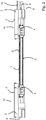
- FIG. 1 shows a sketch of a set of two complementary busbar connectors 1a, 1b.
- the busbar connectors 1 a, 1 b each have an insulating material housing 2 which is closed on the top with a cover 3.
- a first plug contact area 4 with first plug contacts 5 is formed on the side opposite the cover 3.
- This first plug-in contact area 4 and the first plug-in contacts 5 arranged thereon are designed so that the busbar connector 1a, 1b can be plugged with its first plug-in contact area 4 onto the top O of a current-carrying profile 6 in order to connect accessible lines to the first via gaps between webs 7 of the current-carrying profile
- Contact plug contacts 5 electrically conductive.
- a second plug contact area 8 with second plug contacts 9 is formed on the end face of the busbar connectors 1a, 1b.
- the second plug-in contact areas 8 of the two complementary busbar connectors 1a, 1b are oppositely designed to match the contour and the position and design of the second plug-in contacts 9 in such a way that a complementary pair of busbar connectors 1a, 1b with the respective second plug-in contact areas 8 are plugged into one another can be in order to connect corresponding second plug contacts 9 of the two complementary busbar connectors 1a, 1b to one another in an electrically conductive manner. If "one within the other" is spoken of in the present application, it does not matter which one Part surrounds the other part or whether the insulating material housings may only be butted onto one another. It is crucial that the complementary pair of busbar connectors 1a, 1b are formed by their second plug contact areas 8 so that an electrically conductive plug contact can be established between the complementary busbar connectors 1a, 1b on the second plug contact areas 8.
- the plug-in direction S2 of the second plug-in contact areas 8 is structurally predetermined in such a way that it runs in the direction of extent E of the current-carrying profile 6.
- the plug-in direction S1 of the first plug-in contact areas 4, on the other hand, is oriented vertically to the longitudinal direction of the busbar connectors 1a, 1b and the direction of extent E of the current-carrying profile 6 to be contacted.
- the first plug contacts 5 are adapted to this plugging direction S1.
- the busbar connector 1 a, 1 b can each be plugged with its first plug-in contact area 4 onto the upper side O of a respective current-carrying profile 6.
- Figure 2 omits a side view of the set Figure 1 detect. It becomes clear that the busbar connector 1a, 1b is now plugged onto the top O of the current-carrying profile 6. The overall height is only slightly increased. At the end of the current-carrying profiles 6, a plug-in connection for a complementary busbar connector 1a, 1b is then provided with the second plug-in contact areas 8, preferably as an extension of the contacted lines (not visible) in the contacted current-carrying profile 6.
- the electrically conductive connection of two current-carrying profiles 6 is therefore not simply effected by an axial direction, that is to say in the direction of extent E of the current-carrying profile 6, which is inserted into the current-rail couplings.
- the lines of the current guide profile 6 are rather by plugging in the busbar connector 1a, 1b contacted transversely to the direction of extension E and an additional plug contact interface is created with the second plug contact area 8.
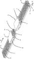
- Figure 3 shows a perspective view of the complementary busbar connectors 1a, 1b in the plugged-on state onto a current-carrying profile 6.
- two current-carrying profiles 6 are arranged one behind the other in the direction of extent E of the current-carrying profiles 6.
- a busbar connector 1a, 1b in a complementary embodiment is plugged onto each of these current-carrying profiles 6.
- the current-carrying profiles 6 have webs 7 which run parallel to one another and run in the direction of longitudinal extent E and have spaces 12 between the webs 7. Lines 13 accessible via the spaces 12 are arranged on the webs 7 or on the bottom of the spaces 12. These are electrically conductively contacted with the first plug contacts 5 of the first plug contact area 4 of the busbar connectors 1a, 1b.
- the two mutually matching busbar connectors 1a, 1b can then be plugged together and electrically conductively contacted.
- two plug contacts 9 are present, which are designed as blade contacts.
- the matching fork contacts are then arranged in the plug contact openings in the insulating material housing 3 of the left busbar connector 1a.
- FIG 4 shows the perspective view from Figure 3 without metal trough 11. It becomes clear that a grounding contact 14 protrudes from the side of the busbar connectors 1a, 1b.
- This grounding contact 14 comes into electrically conductive contact with the busbar 6 when the busbar connector 1a, 1b is plugged the surrounding metal trough 11 when the current-carrying profile 6 in Figure 3 shown is inserted in a metal trough 11.
- the metal trough 11 can thus be reliably grounded.
- This plug contact 15 is designed to lead and has a length that protrudes further out of the busbar connector 1a, 1b than the other second plug contacts 9 in the second plug contact area.
- the grounding contact 14 is thereby separated from one another last when the busbar connectors 1a, 1b are pulled off.
- Figure 5 shows a perspective view of the pair of complementary busbar connectors 1a, 1b. It can again be seen here that the grounding contact 14 is designed with two spring arms 16 protruding in opposite directions.
- a comb-like structure formed with a number of webs 17 can also be seen on the right busbar connector 1b.
- the second plug contacts 5 (not visible) are arranged on the webs 17, so that the first plug contact area 4 is designed to be plugged in a plugging direction S1 perpendicular to the surface on the top and bottom of the busbar connector 1a, 1b and its insulating housing 3.
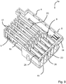
- FIG. 13 shows a perspective view, opened at the top, of a pair of busbar connectors 1a, 1b.
- a number of contact inserts 19 are present in the lower part 18 of the insulating material housing 2. These each consist of a first plug contact 5 of the first plug contact area 4 and an opposing second plug contact 9 of the second plug contact area 8 and a busbar piece 20 connecting these two plug contacts 5, 9 to one another.
- the second plug contacts 9 of the first busbar connector 1a are designed as fork contacts. They have two fork prongs which are connected to one another in a common root section and are directed towards each other in a springy manner. The root area is part of the busbar section 20 or merges into it. The ground contact connection is also provided on the opposite side of the ground contact 14 with such a fork contact 15 as a plug contact.
- the corresponding second busbar connector 1b has in its second plug contact area 8 a number of blade contacts arranged next to one another to form the second plug contacts 9.
- tabs 21 protrude at an angle. These serve to fix the busbar connector 1a, 1b to a metal trough 11 when the busbar connector 1a, 1b is attached to a current-carrying profile 6 arranged in the metal trough 11.
- FIG. 3 shows the pair of busbar connectors 1a, 1b Figure 6 when assembled. It becomes clear that the second plug-in contacts 9 of the right busbar connector, in the form of blade contacts, dip into the second plug-in contacts 9 of the left busbar connector 1a, which are designed as fork contacts, and are electrically contacted there by the fork contacts. It becomes clear that the tabs 21 are then arranged in alignment.
- Figure 8 shows a cross-sectional view through a busbar connector 1 (either busbar connector 1a or complementary busbar connector 1b), which is inserted with its webs 17 into the spaces 12 between the webs 7 of the current-carrying profile 6. Electrical conductors 22 are arranged laterally on these webs 7 of the current-carrying profile 6. These are then electrically conductively contacted with assigned first plug contacts 5 in the form of spring clip or spring arm contacts. These first connectors 5 are arranged on the webs 17 of the busbar connector 1 and protrude laterally from it in an elastically resilient manner.
- a first plug contact 5 can be present on each side of the webs 17 of the busbar connector 1.
- the grounding contact 14 can optionally be contacted in an electrically conductive manner with an assigned conductor 22 in the current-carrying profile 6. This is preferred in order to keep the current paths for current dissipation short.
- busbar connector 1 with its first plug-in contact area 4 for plugging onto the top of the current-carrying profile 6, i.e. is formed on the open side of the spaces 12 and the ends of the webs 7 of the current-carrying profile 6.
- Figure 9 shows a perspective view of an embodiment of a first busbar connector 1a with fork contacts for the second plug contacts 9. These are each arranged on two levels next to one another in order to increase the packing density.
- the lower part 18 of the insulating housing 2 receives the contact inserts 19.
- the first plug contacts are arranged on the webs 17.
- the second plug contact area 8 there are intermediate walls 23 in order to electrically isolate the individual plug contacts 9 arranged next to one another and to form individual chambers. At the top, these chambers are closed off by the bottom 24 of an insulating material insert part 25 which is pushed onto the lower part 18 after the lower contact inserts 19 have been inserted.
- the upper contact parts 19 are then inserted into the insulating material housing 18 and the insulating material insert part 15 in order to arrange a row of second plug contact connections 9 in the upper, second level.
- This insulating material insert 24 has flanges 26 protruding downward from the base 24, with which the available air and creepage distances can be increased further.
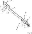
- Figure 10 shows an example of a contact insert 19 for the lower level.
- the contact insert 19 for the upper level is constructed similarly to this.
- the first plug contact 5 has a spring tongue 27 (also called a spring clip) which protrudes from a common busbar piece 20, which electrically connects the fork contact 28 at the opposite end with the spring tongue 27 conductively connects.
- the contact part 19 is formed in one piece from a metal sheet. This can be done easily by punching and bending.
- the spring tongue 27 has contact edges 50 on both sides, which can cut into the line 22 to be contacted when the first plug contact 5 is plugged onto a current-carrying profile 6. The first plug contact 5 for the line 22 is thus fixed in position.
- the second plug contact 9 has a double fork contact with two pairs of fork tongues 29 pointing towards one another, the front free ends of which are bent away from one another. In this way, an insertion funnel for a corresponding knife contact is created.
- the busbar piece 20 has a bent bridge section 30 with which the fork tongues 29 lying opposite one another are connected to one another.
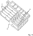
- Figure 11 omits a perspective view of the lower part 18 of the insulating material housing for the busbar connector Figure 9 detect.
- the spaced-apart intermediate walls 23 and webs 17 can be clearly seen, which each extend in the longitudinal direction of the insulating material housing 3 or of the lower part 18.
- the webs 17 are arranged laterally offset from the partition walls 23.
- Figure 12 shows a perspective view of the insulating material insert 25.
- partition walls 23 are arranged at a distance from one another and rest on a common base 24.
- the flanges 26 protruding from the bottom 24 on the side opposite the intermediate walls 23 are also clear.
- a pair of flanges 26 arranged next to one another and aligned parallel to one another provide a gap for receiving an intermediate wall 23 of the lower part 18 of the insulating material housing 2.
- the insulating material insert 25 can thus be pushed onto the lower part 18 and fixed in position there.
- Figure 13 omits a perspective view of the busbar connector 1a Figure 9 Recognize corresponding busbar connector 1b.
- the second plug contacts 9 are designed here as blade contacts. These are again arranged in groups next to one another and on two levels one above the other.
- there is an insulating material insert 25 which is inserted into the lower part 18 of the insulating material housing 2.
- plug-in contours with chambers for receiving the second plug-in contacts 9 are provided. These are then inserted into the chambers of the corresponding first plug connector 1a, the fork contacts 28 then each encompassing a blade contact 32 and making electrically conductive contact.
- the first plug contact area 4 again has first plug contacts 5 with spring clips.
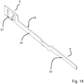
- Figure 14 shows a perspective view of a contact insert 19 for this corresponding busbar connector 1b with blade contact 32 on a spring clip contact 27 on the opposite and a busbar piece 20 connecting these first and second plug contacts 9, 5.
- the second plug contact 9 lies approximately at the level of the contacting of the first plug contact 5 on the same plug level, the in Figure 14
- the contact insert shown is intended for use in the lower level of the busbar connector 1b.
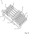
- Figure 15 shows the lower part 18 of the previously described busbar connector 1b without insulating material insert 25 but with inserted contact inserts 19, both in the lower and in the upper level. It becomes clear that the busbar pieces 20, which connect the first and second plug contacts 5, 9 to one another, are guided through the lower part 18 in a bend. It is also clear that the first plug contacts 5 are inserted into the lower part 18 in a fixed position. For this purpose, suitable receiving grooves are provided in the lower part 18. The plug contacts 5 of the lower level lie on a side facing away from the web 17, on which the plug contacts 5 of the upper level are arranged.
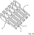
- Figure 16 shows a perspective view of the insulating material insert 25. It becomes clear here that the air and creepage distances between the adjoining second plug contacts 9 are significantly increased by the receiving grooves 34 separated from one another by intermediate gaps 33. This intermediate gap 33 serves to accommodate the intermediate walls 23 of the corresponding busbar connector 1a when the busbar connector 1b is plugged onto the complementary busbar connector 1a.
- Figure 17 shows an exploded view of a four-part insulating material housing 2 for a further embodiment of a busbar connector. Again a lower part 18 is provided which is covered by a cover part 3.
- the insulating material insert 25 is also made in two parts in this embodiment and consists of a lower part 35 and an upper part 36. These parts of the insulating material housing 2 have contours for receiving the contact inserts 19 and for providing a plug contour in the second plug contact area 8 on the end face of the assembled insulating material housing 2.
- Figure 18 shows the two different contact inserts 19 that are in this busbar connector 1 from Figure 17 can be used.
- the two different contact inserts 19 are shown rotated by 180 degrees with respect to one another in two orientations.
- the lower contact insert 19 is the earth contact connection with the earth contact 14 on one side and a blade contact 32 on the opposite side, as well as a busbar piece 20 connecting these two contacts 14, 32 to one another.
- the other contacts have a spring clip on one side and a blade contact 32 on the opposite side.
- the first plug contact 5 and the opposite, second plug contact 9 are connected to one another via a busbar piece 20. This has a U-shaped bend.
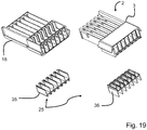
- Figure 19 shows an exploded view of an insulating housing 2, also formed from four parts, for the busbar connector complementary thereto. Its structure can essentially be based on the description Figure 9 to get expelled. Here too, however, the insulating material insert 25 is formed from two parts 35, 36.
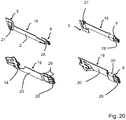
- Figure 20 shows the contact inserts 19 provided for this busbar connector 1, each in two orientations rotated by 180 ° to one another.
- the contact inserts 19 in the upper area again have a spring tongue 27 for forming the first plug contact 5 and on the opposite side a fork contact 28 for forming the second plug contact 9.
- the fork contact 28 for the grounding contact connection shown below is formed from three pairs of fork tongues 29 arranged one above the other. This increases the contact force and the current cross-section in comparison to the contact parts 19 arranged above, which is particularly important for the ground contact.
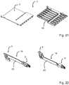
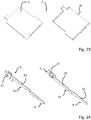
- Figures 21 to 24 show the insulating material housing 2 with lower part 18 and cover 3 as well as the associated contact inserts 19 provided for the formation of complementary single-row busbar connectors 1a, 1b educated.
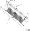
- Figure 25 shows a detail view of a metal trough 11 with a current-carrying profile 6 received therein.
- fastening elements 37 are formed on the metal trough 11, for example in the form of protruding knobs. These fastening elements 37 are provided in order to fix a busbar connector 1a, 1b plugged onto the current-carrying profile 6 on the metal trough 11. This can be done by a latching connection, a screw connection or the like.
- the fastening elements 37 can also simply be designed as bores for receiving sheet metal screws.
- FIG 26 shows the detail view Figure 25 with busbar connector 1b now attached. It becomes clear here that the busbar connector 1b has a fastening area on one side with a fastening element 38 that matches the fastening element 37 of the metal trough 11. The busbar connector 1b can thus be latched onto the metal trough 11, for example.
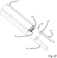
- FIG. 11 shows a perspective view of a metal trough 11 with a busbar connector 1b, which is plugged onto an invisible current-carrying profile 6 in the metal trough 11.
- This busbar connector 1b is covered by a connecting element 39, more precisely with a holding plate 40 of the connecting element 39.
- the connecting element 39 has mutually opposite side guide wall sections 41 which are inserted on the left side into the profile of the metal trough 11, so that the connecting element is aligned in alignment with the metal trough 11.
- a further metal trough 11 with a current-conducting profile 6 arranged thereon can then be attached to the guide wall sections 41 and pushed to the metal trough 11 located behind with the aid of the guide wall sections 41.
- a busbar connector 1a already plugged onto the current-carrying profile 6 is in this way guided to the busbar connector 1b in the correct position and position, so that they enter into an electrically conductive plug contact when two metal troughs 11 are pushed onto one another.
- the busbar connector 1a, 1b also protrude a guide finger 42 which engages in a corresponding guide opening in the opposite, complementary busbar connector 1a, 1b.
- FIG. 11 shows a cross-sectional view through the metal trough 11 from FIG Figure 27 . It becomes clear that the holding plate 40 rests on the top of the busbar connector 1 and holds it firmly on the busbar 6.
- the guide wall sections 41 on the opposite sides then rest on the side walls 43 of the metal trough 11 and can also be guided in corresponding guide grooves or on the corresponding contours.
- Figure 29 shows a perspective view of two metal troughs 11, which can be pushed towards one another in the direction of the arrow, with current-carrying profiles 6 received therein and busbar connectors 1a, 1b already attached to the current-carrying profiles 6 before assembly.
- the connecting element 39 With the help of the connecting element 39, it is possible not only to hold the already plugged-on busbar connectors 1a, 1b over the holding plate on the current-carrying profiles 6, but also to move the metal troughs 11 in alignment with one another with the help of the guide wall sections 41. In this case, the busbar connectors 1a, 1b that have already been attached are fed to one another in the correct position and plug-in contact with one another.
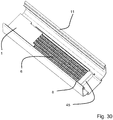
- Figure 30 shows a view of a current-carrying profile 6 installed in a metal trough 11 with a busbar connector 1 pushed onto it. It is clear that the current-carrying profile 6 is covered on the front side with a protective cap 45.
- Figure 31 shows a detail view of a metal trough 11 with a current-carrying profile 6 built into it and a busbar connector 1 pushed onto it.
- a protective cap 46 is pushed onto the end piece of the metal trough 11, which is a Provides transport protection.
- This protective cap 46 can be provided for manual removal before the second busbar connector 1a, 1b is plugged together.
- the protective cap 46 has a contour designed in such a way that the protective cap 46 automatically loosens and falls off when an adjacent metal trough 11 is attached or, if applicable, only when a corresponding busbar connector 1a, 1b is plugged on.
- protruding webs 47 can be provided on the inside of the protective cap 46.
- Figure 32 shows the metal trough 11 with the protective cap 46 pushed on at the end Figure 31 facing the outside.
- the protective cap 46 is adapted to the cross-sectional contour of the metal trough 11.
- Figure 33 shows a perspective view of the protective cap 46. It becomes clear that holding tabs protrude from the opposite edge edges, which rest on the edge edges of the metal trough 11 in the pushed-on state and hold the protective cap 46 on the metal trough 11. End stops 49 can also be seen in the form of transverse webs, which form a stop for a metal trough 11 when the protective cap 46 is pushed onto the metal trough.
- Figure 34 shows a variant of the busbar connector 1a, 1b in which the plug contacts 9 are rounded at the ends.
- the plug contacts 9 can be arranged on two contact levels as shown.
- the rounded version is basically independent of the number of plug levels.
Landscapes
- Connector Housings Or Holding Contact Members (AREA)
- Details Of Connecting Devices For Male And Female Coupling (AREA)
Description
- Die Erfindung betrifft einen Stromschienenverbinder zur elektrisch leitenden Verbindung von Leitungen an Stegen eines Stromführungsprofils, wobei der Stromschienenverbinder ein Isolierstoffgehäuse und eine Mehrzahl von paarweise elektrisch leitend miteinander verbundenen ersten und zweiten Steckkontakten hat.
- Die Erfindung betrifft weiterhin ein Set aus einem Stromführungsprofil und Stromschienenverbinder zur elektrisch leitenden Verbindung von Leitungen an Stegen des Stromführungsprofils, das eine Oberseite hat, an der Leitungen über zwischen den Stegen zugänglich sind, wobei der Stromschienenverbinder ein Isolierstoffgehäuse und eine Mehrzahl von paarweise elektrisch leitenden miteinander verbundenen ersten und zweiten Steckkontakten hat.
- Solche Stromführungsprofile werden insbesondere für Beleuchtungsanlagen in Gebäuden eingesetzt, um Leitungen zur Versorgung von Geräten, wie insbesondere von Leuchten oder sonstigen mit Energie und/oder Daten zu versorgenden Geräten kostengünstig und optisch ansprechend zu verlegen. Der Einbauort der Geräte kann dann flexibel entlang der Stromschiene gewählt und leicht variiert werden. Die Geräte können dann nicht nur einfach mit einem Steckverbinder auf einfache Weise elektrisch leitend mit den Leitungen an einem variabel festlegbaren Einbauort kontaktiert werden. Solche Stromschienensysteme haben auch den Vorteil, dass die Geräte zugleich mechanisch an der Stromschiene getragen werden können.
- Zur Verbindung mehrerer aneinander angrenzenden Stromführungsprofile wird z.B. in der
US 4,053,194 A ein Verbindungselement vorgeschlagen, das in die stirnseitig offenen Stromführungsprofile in deren Stirnseite eingesetzt und dort über eine Schraubverbindung mit dem Stromführungsprofil verspannt oder verschraubt wird. Der Stromschienenverbinder ist aus einem einteiligen Isolierstoffmaterial gebildet, in das Kontaktelemente für die stromführenden Leitungen der Stromführungsprofile und Leitungskontaktverbinder zwischen diesen Kontaktelementen integriert sind. Die Energiezuführung an die stromführenden Leitungen der Stromführungsprofile kann durch in den Stromschienenverbinder integrierte Leitungen erfolgen. -
DE 35 02 864 C2 offenbart eine Vorrichtung zur stumpfen elektrischen Verbindung der Enden von parallel nebeneinanderliegenden Stromschienen. An den Enden der Stromschienen anliegende Verbindungsstücke bestehen aus mäanderförmig gebogenen Paketen von biegsamen, längenveränderbaren Metallbändern mit Dehnungsschleifen. -
US 6,296,498 B1 offenbart einen Stromschienenverbinder, der wiederum axial in Erstreckungsrichtung der Stromführungsprofile in diese eingeschoben wird. Dabei werden an den Seitenwänden des Stromführungsprofils befindliche Leiter durch seitlich vorstehende Steckkontakte des Stromschienenverbinders kontaktiert. - Als Alternative zu den axial in Erstreckungsrichtung der Stromführungsprofile einsteckbaren Stromschienenverbindern ist in der
US 2003/021111 A1 eine Variante gezeigt, bei der mittels Kabeln elektrisch leitend miteinander verbundene Paare von Stromschienenverbindern auf die Oberseite der Stromführungsprofile aufgesteckt werden. Die elektrisch leitende Verbindung wird dann im Abstand zu der Stelle der aufeinanderfolgenden Stromführungsprofile hergestellt. Die Steckkontakte sind an die kammartige Struktur der Stromschiene angepasst, um in diese von der Oberseite hineingesteckt zu werden und dabei die in den durch die Stege der kammartigen Struktur gebildeten Nuten geführten Leitungen zu kontaktieren. - In entsprechender Weise wird auch in
EP 2 091 113 A1 vorgeschlagen, zwei kammartige Stromführungsprofile mit Hilfe von einem Paar von Steckverbindern miteinander elektrisch leitend zu kontaktieren, die ihrerseits wiederum durch ein Flachbandkabel oder Drahtleiter elektrisch leitend miteinander verbunden sind. Die Stromschienenverbinder werden vertikal zur Erstreckungsrichtung der Stromführungsprofile auf diese aufgesteckt. -
DE 10 2010 032 383 B4 offenbart einen Stromschienenverbinder mit zwei in Längserstreckungsrichtung verschiebbar zueinander gelagerten Isolierstoffgehäuseteilen. An den beiden Enden des Isolierstoffgehäuses sind Steckkontaktabschnitte mit an einer Unterseite des Isolierstoffgehäuses abragenden Steckkontakten vorhanden. Diese Steckkontaktabschnitte werden auf die Oberseite des Stromführungsprofils aufgesteckt. Die Steckkontakte der beiden gegenüberliegenden Steckkontaktbereiche sind über Leiterkontaktverbinder miteinander elektrisch leitend verbunden, die in Führungsnuten des Isolierstoffgehäuses aufgenommen sind. In ähnlicher Weise enthüllt das DokumentDE102010055789 A1 einen Verbinder mit zwei Steckkontaktabschnitten als Verbindung zwischen zwei Stromschienen. - Bei der Montage der Stromführungsprofile, die in der Regel in einem Metalltrog aufgenommen sind, müssen erst einmal die Stromführungsprofile ausgerichtet und z.B. an einer Gebäudedecke befestigt werden. Anschließend erfolgt dann in einem separaten Schritt die elektrisch leitende Verbindung durch Aufstecken der Stromschienenverbinder. Dies ist arbeitsaufwändig und erfordert Fachpersonal.
WO 2013 / 104 766 A1 zeigt einen Stromschienenverbinder, wobei der Stromschienenverbinder Kontaktfüße hat, die nebeneinanderliegende Leiterbahnen miteinander elektrisch Leitend verbindet, indem die Kontaktfüße von oben auf die Leiterbahnen aufgelegt werden. Der Stromschienenverbinder kann einen Steckanschluss für elektrische Leiter haben, um die elektrischen Leiter mit einer der Leiterbahnen elektrisch leitend zu verbinden.
Ausgehend hiervon ist es daher Aufgabe der vorliegenden Erfindung, ein verbessertes Set aus einem Stromführungsprofil und einem Stromschienenverbinder, sowie einen verbesserten Stromschienenverbinder zu schaffen. - Die Aufgabe wird mit einem Stromschienenverbinder mit den Merkmalen des Anspruchs 1 gelöst. Vorteilhafte Ausführungsformen sind in den Unteransprüchen beschrieben.
- Mit Hilfe des zweiten Steckkontaktbereichs des ersten Stromschienenverbinders wird eine Steckkontaktierung für einen komplementären Stromschienenverbinder bereitgestellt, der in axialer Richtung, d.h. in Richtung der Erstreckung der miteinander leitend zu verbindenden Stromführungsprofile auf den ersten Stromschienenverbinder aufgesteckt wird. Dann hat das Set von Stromschienenverbinder und komplementären Stromschienenverbinder drei Schnittstellen, wobei die voneinander beabstandeten ersten Steckkontaktbereiche eine Schnittstelle zum vertikalen Aufstecken auf die Stromführungsprofile und die zweiten Steckkontaktbereiche eine Schnittstelle zum axialen Aufeinanderstecken der Stromschienenverbinder bereitstellt.
Während im Stand der Technik entweder längenveränderliche fertig montierte Stromschienenverbinder mit zwei voneinander beabstandeten Steckkontaktbereichen zum Aufstecken auf ein Stromführungsprofil oder Stromschienenkupplungen zum axialen Einstecken in einer Flucht nebeneinander angeordneten Stromführungsprofile vorhergesehen sind, wird nun ein anderer Weg vorgeschlagen.
Es wird zur elektrischen Verbindung der Stromführungsprofile das Prinzip des vertikalen Aufsteckens auf einen ersten Steckkontaktbereich mit ersten Steckkontakten zur Steckkontaktierung der Leitung des Stromführungsprofils genutzt, wobei der Stromschienenverbinder auf die Oberseite des Stromführungsprofils aufgesteckt wird. Damit wird ermöglicht, dass sich die ersten Steckkontakte axial in Erstreckungsrichtung der Leitungen unbeweglich mit den Leitungen verkrallen können. Der Langzeitkontakt wird damit wesentlich verbessert und insbesondere einer Bildung von Oxidschichten mit der damit einhergehenden Erhöhung der Übergangswiderstände entgegengewirkt. - Zusätzlich wird allerdings dann auch eine Schnittstelle zur axialen Steckverbindung mit den zweiten Steckkontaktbereichen bereitgestellt. Dies hat wie bei den Stromschienenkupplungen den Vorteil, dass eine elektrisch leitende Verbindung von hintereinander in einer Flucht anzuordnender Stromführungsprofile direkt im Schritt des Aneinanderreihens von Stromführungsprofiles hergestellt werden kann. Diese elektrisch leitende Verbindung wird aber nicht durch Steckkontaktierung der Leitung der Stromführungsprofile in axialer Richtung realisiert, sondern durch eine weitere Steckverbindung, die in Erstreckungsrichtung der Stromführungsprofile, d.h. in axialer Richtung wirkt. Durch die zweiten Steckkontakte kann dabei ein zuverlässiger, langzeitstabiler Kontakt am Stromschienenverbinder selbst bereitgestellt werden. Die Kontaktbedingungen werden damit ausschließlich durch die Stromschienenverbinder vorgegeben und sind nicht von den Bedingungen des Stromführungsprofils abhängig.
- Anders als beim Abgriff zum Anschluss von Geräten an ein Stromführungsprofil sind an die elektrisch leitende Verbindung der Leitungen von Stromführungsprofilen miteinander größere Anforderungen zu stellen. Die dort fließenden Ströme sind in der Regel nämlich wesentlich höher, als die in ein einzelnes Gerät abfließenden Ströme. Zudem wirken sich Wärmeausdehnungen der Leitungen bei der Verbindung aufeinanderfolgende Stromführungsprofile auf die Zuverlässigkeit der Steckkontaktierung aus. Eine Bewegung der Steckkontakte relativ zum Leiter kann bereits bei sehr geringen Bewegungen zu Reibkorrosion und dem Aufbau von Oxidschichten führen, was zur hochohmigen Verbindung und Wärmeentwicklung führt. Dem kann durch die Nutzung von auf die Oberseite des Stromführungsprofils aufsteckbaren ersten Steckkontaktbereichen auf einfache und sichere Weise entgegengewirkt werden. Dem sich hieraus ergebenden Nachteil, dass die Stromschienenverbinder dann erst nachträglich nach der Installation der Stromführungsprofile auf diese aufgesteckt werden können, wird durch die Bereitstellung einer zusätzlichen Schnittstelle zur axialen Stecckontaktierung über die zweiten Steckkontaktbereiche entgegengewirkt.
- Die zweiten Steckkontakte des zweiten Steckkontaktbereichs können als Messerkontakte und/oder Gabelkontakte ausgeführt sein. So können die zweiten Steckkontakte des ersten Stromschienenverbinders als Messerkontakte und die Steckkontakte eines komplementären Stromschienenverbinders als Gabelkontakte ausgeführt sein. Denkbar ist aber auch eine Kombination derart, dass ein Steckverbinder für mehrere zweite Steckkontakte eine Variation von Messer- und Gabelkontakten und der komplementäre Steckverbinder, der zum Aufstecken auf den Steckverbinder vorgesehen ist, eine entsprechend hieran angepasste komplementäre Variation von Gabel- und Messerkontakten aufweist. Weiterhin ist auch ein hermaphroditischer Steckkontakt mit Messer- und/oder Gabelkontakten denkbar.
- Die Steckverbindung von zwei Stromschienenverbindern mit Hilfe von Messer- und Gabelkontakten ermöglicht einen zuverlässigen Steckkontakt auch für hohe Ströme, der langzeitstabil ist und sich einfach und zuverlässig realisieren lässt. Die Messer- und Gabelkontakte sind zudem sehr kompakt ausführbar.
- Die ersten Steckkontakte zum Aufstecken auf die Stromführungsprofile und Kontaktierung an Stegen der Stromführungsprofile angeordnete Leitungen können jeweils zumindest eine Federzunge aufweisen. Damit wird eine elektrisch leitende Kontaktierung des Stromschienenverbinders mit Leitungen durch Ausnutzung von Federkräften der Federzungen ermöglicht. Während bei Gabelzungen von zwei Gabelzinken aufeinander zuweisende Kräfte auf den zwischenliegenden Messerkontakt ausgeübt werden, wird bei den Federzungen nur von einer Seite eine Kontaktkraft auf die zu kontaktierende Leitung ausgeübt.
- Die Federzungen können zumindest eine seitlich vorstehende Kontaktkante haben. Dies hat den Vorteil, dass sich die Federzungen beim Aufstecken in den zu kontaktierenden Leitungen des Stromführungsprofils verkrallen. Damit kann eine Relativbewegung der Steckkontakte zu den Leitungen entlang der Erstreckungsrichtung der Leitungen auf einfache Weise unterbunden werden.
- An dem ersten Steckkontaktbereich können Stege ausgebildet sein, die zum Einstecken in den Zwischenraum benachbarter Stege des Stromführungsprofils vorgesehen sind und jeweils die ersten Steckkontakte tragen, wobei beidseits des Steges jeweils ein Steckkontakt angeordnet sein kann. Diese Stege dienen somit zur Aufnahme der ersten Steckkontakte und zur Führung des Stromschienenverbinders mit seinem ersten Steckkontaktbereich in den Zwischenraum zwischen den Stegen des zu kontaktierenden Stromführungsprofils hinein, wenn der Stromschienenverbinder an der Oberseite auf das Stromführungsprofil aufgesteckt wird. Zudem stellen die Stege eine elektrische Isolation benachbarter Steckkontakte sicher.
- Die zweiten Steckkontakte können dann in Steckrichtung beweglich in dem Isolierstoffgehäuse gelagert sein. Dies hat den Vorteil, dass Relativbewegungen der in einer Flucht hintereinander angeordneten Stromführungsprofile an der Schnittstelle zwischen dem Stromschienenverbinder und dem daran aufgesteckten komplementären Stromschienenverbinder im zweiten Steckkontaktbereich ausgeglichen werden. Die Steckkontaktierung der zweiten Steckkontakte des Stromschienenverbinders und des daran aufgesteckten komplementären Stromschienenverbinders wird bei einer solchen axialen Bewegung nicht beeinträchtigt. Der Längenausgleich erfolgt dann jeweils in der Verbindung der beweglich gelagerten zweiten Steckkontakte mit den zugeordneten ersten Steckkontakten desselben Stromschienenverbinders. Dabei kann das gesamte Kontaktpaar bestehend aus den paarweise elektrisch leitend miteinander verbundenen ersten und zweiten Steckkontakten und dem zwischenliegenden Stromschienenstück beweglich in dem Isolierstoffgehäuse aufgenommen sein. Damit wird sichergestellt, dass sich jedes der Steckkontakte eines Kontaktpaares unabhängig voneinander bewegen kann, wenn sich einzelne Leitungen in dem Stromführungsprofil unterschiedlich zueinander ausdehnen.
- Die Paare von ersten und zweiten Steckkontakten können über ein Stromschienenstück oder eine flexible Leitung miteinander verbunden sein. Das Stromschienenstück kann dabei einen flexiblen, z.B. mäanderförmigen Abschnitt haben, um einen Längentoleranzausgleich bereitzustellen. Das Stromschienenstück kann aber auch mehrteilig sein und eine Kupplung zum Ausgleich von Bewegungen in axialer Richtung bei Sicherstellung eines guten Kontakts haben.
- Die Paare von ersten und zweiten Steckkontakten können einstückig mit einem die Steckkontakte verbindenden Stromschienenstück gebildet sein. Sie können dann einfach als z.B. aus einem Metallblech ausgeformtes Teil in das Isolierstoffgehäuse eingelegt werden. Dies ermöglicht eine einfache Montage und einen zuverlässigen Aufbau des Stromschienenverbinders.
- Das Isolierstoffgehäuse kann Befestigungselemente oder Befestigungskonturen zur Fixierung an dem Stromführungsprofil oder einem das Stromführungsprofil tragenden bzw. aufnehmenden Metalltrog haben. Damit wird der Gefahr weiter vorgebeugt, dass sich die am ersten Steckkontaktbereich vorhandenen Kontakte relativ zu den Leitungen des Stromführungsprofils bewegen. Der Stromschienenverbinder wird auf diese Weise ortsfest mit dem zugeordneten Stromführungsprofil verbunden, auf das der Stromschienenverbinder aufgesteckt ist. Alternativ erfolgt die Festlegung mit dem das Stromführungsprofil aufnehmenden Metalltrog.
- Weiterhin ist es denkbar, dass der Stromschienenverbinder eine Schutzkappe zur Abdeckung des zweiten Steckkontaktbereiches hat. Damit ist ein Transportschutz vorhanden, der bei der Montage der Lichtbänder entfernt werden kann. Diese Schutzkappe kann eine zum selbsttätigen Lösen der Schutzkappe von dem zweiten Steckkontaktbereich beim Aufstecken des komplementären Stromschienenverbinders auf den zweiten Steckkontaktbereich ausgebildete Kontur haben. Damit wird auf jeden Fall sichergestellt, dass eine Berührung der zweiten Steckkontakte im zweiten Steckkontaktbereich unmöglich ist, auch wenn der Stromschienenverbinder auf ein Stromführungsprofil aufgesteckt ist. Diese Schutzkappe wird dann erst beim Aufstecken eines komplementären Stromschienenverbinders entfernt. Dieses erfolgt aber auch nicht einfach manuell mit der Folge, dass die zweiten Steckkontakte dann doch noch temporär nicht berührungsgeschützt wären. Vielmehr wird durch eine geeignete Kontur der Schutzkappe sichergestellt, dass sie sich selbsttätig beim Aufstecken des komplementären Stromschienenverbinders von dem zweiten Steckkontaktbereich löst. Dies kann durch eine Rastverbindung und Führungsvorsprünge realisiert sein, die mit dem komplementären Stromschienenverbinder und/oder dem Stromführungsprofil und/oder dem Metalltrog zusammenwirken, der dann die Rastverbindung aufhebt und durch den Aufschiebevorgang die Schutzkappe von dem zweiten Steckkontaktbereich wegbewegt.
- Der zweite Steckkontaktbereich kann ohne Rastmittel zur beweglichen Steckverbindung der Isolierstoffgehäuse und der darin aufgenommenen zweiten Steckkontakte des Stromschienenverbinders und eines komplementären Stromschienenverbinders ausgebildet sein. Dies hat den Vorteil, dass die Steckverbindung zwischen Stromschienenverbinder und komplementären Stromschienenverbinder in axialer Richtung beweglich bleibt. Damit ist ein Toleranzausgleich in der Verbindung der zweiten Steckkontakte miteinander sichergestellt.
- Elektrisch voneinander getrennte zweite Steckkontakte eines Stromschienenverbinders, die zur Kontaktierung voneinander unterschiedliche Leitungen des Stromführungsprofils vorgesehen sind, können in zwei Ebenen übereinander angeordnet sein. Der zweite Steckkontaktbereich hat dann ein Isolierstoffeinlegeteil mit einem die beiden Ebenen voneinander abtrennenden Boden und mit Trennwänden zwischen in einer gemeinsamen Ebene nebeneinander angeordneten zweiten Steckkontakten. Auf diese Weise kann der zweite Steckkontaktbereich sehr kompakt ausgestaltet werden. Mithilfe des zusätzlichen Isolierstoffeinlegeteils gelingt es dann, die erforderlichen Luft- und Kriechstrecken zwischen den neben- und übereinander angeordneten zweiten Steckkontakten bereitzustellen und eine schnelle und einfache Montage der zweiten Steckkontakte in dem Isolierstoffgehäuse zu ermöglichen.
- Der Stromschienenverbinder kann einen voreilenden Erdungskontaktanschluss mit einem an einer Seitenwand des Isolierstoffgehäuses zur Steckkontaktierung eines Metalltrogs, in dem das Stromführungsprofil aufgenommen ist, haben, wenn der Stromschienenverbinder auf das im Metalltrog angeordnete Stromführungsprofil aufgesteckt ist. Mithilfe dieses zusätzlichen Erdungskontaktanschlusses wird eine durchgehende Erdung des Metalltrogs auf einfache und zuverlässige Weise sichergestellt. Der Erdungskontaktanschluss kontaktiert den Metalltrog beim Aufstecken des Stromschienenverbinders auf das Stromführungsprofil dann mit dem an der Seitenwand des Isolierstoffgehäuses vorhandenen Erdungskontakt.
- Der oben beschriebene Stromschienenverbinder stellt als Set aus zwei komplementären Stromschienenverbindern, die über ihre zweiten Steckkontaktbereiche miteinander steckkontaktiert werden, eine elektrisch leitende Verbindung zwischen zwei in einer Flucht hintereinander angeordneten Stromführungsprofilen bereit. Diese Stromführungsprofile sind in der Regel in einem Metalltrog aufgenommen.
- Zur mechanischen Verbindung der in einer Flucht hintereinander angeordneten Metalltröge kann ein Verbindungselement vorhanden sein, das Führungsabschnitte zum Einschieben in zwei miteinander zu verbindenden Metalltröge aufweist. Das Verbindungselement kann zusätzlich noch eine Halteplatte zur Auflage auf den Stromschienenverbindern und zur Führung eines auf ein Stromführungsprofil eines ersten Metalltrogs aufgesteckten Stromschienenverbinders zum zweiten Steckkontaktbereich eines auf ein Stromführungsprofil eines zweiten Metalltrogs aufgesteckten komplementären Stromschienenverbinders haben. Mithilfe eines solchen Verbindungselementes gelingt es somit nicht nur, die in Längserstreckungsrichtung der Metalltröge hintereinander angeordneten Metalltröge mechanisch miteinander zu verbinden. Vielmehr kann mithilfe der Halteplatte auch der Stromschienenverbinder vor einem Abrutschen an der Oberseite des Stromschienenführungsprofils gehalten werden. Zudem wird mit der Halteplatte eine Führung der miteinander über ihre zweiten Stecckontaktbereiche zu kontaktierenden Stromschienenverbinder aufeinander erreicht.
- Die Erfindung wird nachfolgend anhand von Ausführungsbeispielen mit den beigefügten Zeichnungen näher erläutert. Es zeigen:
- Figur 1
- - Seitenansicht eines Sets aus zwei Stromschienenverbindern und einer Stromschiene;
- Figur 2
- - Set aus
Figur 1 im aufgesteckten Zustand der Stromschienenverbinder; - Figur 3
- - Perspektivische Ansicht eines Sets aus zwei Stromschienenverbindern und zwei Metalltrögen mit darin jeweils aufgenommenen Stromführungsprofilen;
- Figur 4
- - Perspektivische Ansicht zweier komplementärer Stromschienenverbinder, die jeweils auf ein Stromführungsprofil aufgesetzt sind;
- Figur 5
- - Perspektivische Ansicht von zwei komplementären Stromschienenverbindern;
- Figur 6
- - Perspektivische Ansicht des Stromführungsverbinders aus
Figur 5 im geöffneten Zustand ohne Abdeckung; - Figur 7
- - Perspektivische Ansicht der Stromschienenverbinder aus
Figur 6 im zusammengesteckten Zustand; - Figur 8
- - Querschnittsansicht durch einen auf ein Stromführungsprofil aufgesteckten und mit einem Metalltrog elektrisch leitend verbundenen Stromschienenverbinder;
- Figur 9
- - Perspektivische Ansicht einer Ausführungsform eines Stromschienenverbinders im geöffneten Zustand;
- Figur 10
- - Perspektivische Ansicht eines Steckverbinderpaares für den Stromschienenverbinder aus
Figur 9 ; - Figur 11
- - Perspektivische Ansicht des Isolierstoffgehäuses des Stromschienenverbinders aus
Figur 9 und10 ; - Figur 12
- - Perspektivische Ansicht eines Isolierstoffeinlegeteils für den Stromschienenverbinder aus
Figur 9 und10 ; - Figur 13
- - Perspektivische Ansicht eines komplementären Stromschienenverbinders im geöffneten Zustand;
- Figur 14
- - Perspektivische Ansicht eines Steckverbinderpaares für den Stromschienenverbinder aus
Figur 13 ; - Figur 15
- - Perspektivische Ansicht des Isolierstoffgehäuses des Stromschienenverbinders aus
Figur 13 mit eingelegten Stromschienenpaaren; - Figur 16
- - Perspektivische Ansicht eines Isolierstoffeinlegeteils für den Stromschienenverbinder aus
Figur 15 ; - Figur 17
- - Explosionsansicht des aus vier Einzelteilen bestehenden Isolierstoffgehäuses für eine andere Ausführungsform eines Stromschienenverbinders;
- Figur 18
- - Perspektivische Ansicht von vier unterschiedlichen Steckverbinderpaaren für den Stromschienenverbinder aus
Figur 17 ; - Figur 19
- - Perspektivische Ansicht des aus vier Teilen gebildeten Isolierstoffgehäuses eines weiteren Steckverbinders;
- Figur 20
- - Perspektivische Ansicht von vier unterschiedlichen Steckverbinderpaaren für den Stromschienenverbinder aus
Figur 19 ; - Figur 21
- - Perspektivische Ansicht des Ober- und Unterteils eines Isolierstoffgehäuses für eine weitere Ausführungsform eines Stromschienenverbinders mit einer Anschlussebene;
- Figur 22
- - Perspektivische Ansicht des Steckverbinderpaares in jeweils zu 180 Grad zueinander verdrehter Anordnung für den Stromschienenverbinder aus
Figur 21 ; - Figur 23
- - Perspektivische Ansicht des Ober- und Unterteils des Isolierstoffgehäuses für einen komplementären Stromschienenverbinder;
- Figur 24
- - Perspektivische Ansicht des Steckverbinderpaares in jeweils zu 180 Grad zueinander verdrehter Anordnung für den Stromschienenverbinder aus
Figur 23 ; - Figur 25
- - Perspektivische Ausschnittsansicht eines Metalltrogs mit darin angeordnetem Stromführungsprofil und Befestigungselementen an dem Metalltrog zur Fixierung eines Stromschienenverbinders;
- Figur 26
- - Perspektivische Ansicht des Metalltrogs mit Stromführungsprofil und darauf aufgestecktem Steckverbinder mit Befestigungselement zur Befestigung an dem Metalltrog;
- Figur 27
- - Perspektivische Ansicht eines Metalltrogs mit auf ein Stromführungsprofil im Metalltrog aufgesteckten Stromschienenverbinder und zusätzlichem Verbindungselement;
- Figur 28
- - Querschnittsansicht durch den Metalltrog aus
Figur 27 und mit dem Verbindungselement; - Figur 29
- - Perspektivische Ansicht von zwei in Pfeilrichtung aufeinander schiebbaren Metalltrögen und mit Verbindungselement;
- Figur 30
- - Perspektivische Ansicht eines Metalltrogs mit Stromführungsprofil und endseitiger Schutzkappe auf dem Stromführungsprofil;
- Figur 31
- - Ausschnittansicht eines Metalltroges mit darauf aufgeschobener Schutzkappe;
- Figur 32
- - Perspektivische Ansicht des Metalltroges mit endseitig aufgeschobener Schutzkappe aus
Figur 31 mit Blick auf die Außenseite; - Figur 33
- - Perspektivische Ansicht der Schutzkappe;
- Figur 34
- - Variante der Stromschienenverbinder mit endseitig abgerundeten Steckkontakten.
-
Figur 1 lässt eine Skizze eines Sets aus zwei komplementären Stromschienenverbindern 1a, 1b erkennen. Die Stromschienenverbinder 1a, 1b haben jeweils ein Isolierstoffgehäuse 2, das an der Oberseite mit einem Deckel 3 abgeschlossen ist. Auf der dem Deckel 3 gegenüberliegenden Seite ist ein erster Steckkontaktbereich 4 mit ersten Steckkontakten 5 ausgebildet. Dieser erste Steckkontaktbereich 4 und die daran angeordneten ersten Steckkontakte 5 sind so ausgebildet, dass der Stromschienenverbinder 1a, 1b jeweils mit seinem ersten Steckkontaktbereich 4 auf die Oberseite O eines Stromführungsprofils 6 aufsteckbar ist, um über Zwischenräume zwischen Stegen 7 des Stromführungsprofils zugängliche Leitungen mit den ersten Steckkontakten 5 elektrisch leitend zu kontaktieren. An der Stirnseite der Stromschienenverbinder 1a, 1b ist ein zweiter Steckkontaktbereich 8 mit zweiten Steckkontakten 9 ausgebildet. Die zweiten Steckkontaktbereiche 8 der beiden komplementären Stromschienenverbinder 1a, 1b sind dabei gegensätzlich und passend zueinander von der Kontur und von der Position und Gestaltung der zweiten Steckkontakte 9 so ausgebildet, dass ein komplementäres Paar von Stromschienenverbindern 1a, 1b mit den jeweiligen zweiten Steckkontaktbereichen 8 ineinander gesteckt werden können, um korrespondierende zweite Steckkontakte 9 der beiden komplementären Stromschienenverbinder 1a, 1b elektrisch leitend miteinander zu verbinden. Wenn in der vorliegenden Anmeldung von "ineinander" gesprochen wird, dann ist es unerheblich, welcher Teil den anderen Teil umgibt oder ob die Isolierstoffgehäuse unter Umständen nur stumpf aufeinander aufgesteckt werden. Entscheidend ist, dass das komplementäre Paar von Stromschienenverbindern 1a, 1b durch ihre zweiten Steckkontaktbereiche 8 so ausgebildet sind, dass eine elektrisch leitende Steckkontaktierung zwischen den komplementären Stromschienenverbindern 1a, 1b an den zweiten Steckkontaktbereichen 8 hergestellt werden kann. - Dabei ist die Steckrichtung S2 der zweiten Steckkontaktbereiche 8 konstruktiv so vorgegeben, dass sie in Erstreckungsrichtung E des Stromführungsprofils 6 verläuft.
- Die Steckrichtung S1 der ersten Steckkontaktbereiche 4 ist hingegen vertikal zur Längserstreckungsrichtung der Stromschienenverbinder 1a, 1b und der Erstreckungsrichtung E des zu kontaktierenden Stromführungsprofils 6 ausgerichtet. Die ersten Steckkontakte 5 sind an diese Steckrichtung S1 angepasst. So kann der Stromschienenverbinder 1a, 1b jeweils mit seinem ersten Steckkontaktbereich 4 auf die Oberseite O eines jeweiligen Stromführungsprofils 6 aufgesteckt werden. Wenn nun zwei in einer Flucht hintereinander angeordneten Stromführungsprofile 6 elektrisch leitend miteinander verbunden werden sollen, so erfolgt dies durch Aufstecken zweier komplementärer Stromschienenverbinder 1a, 1b, die jeweils auf den beiden zu verbindenden Stromführungsprofilen 6 aufgesteckt sind, in axialer Richtung der Stromführungsprofile 6, d.h. in Erstreckungsrichtung E.
-
Figur 2 lässt eine Seitenansicht des Sets ausFigur 1 erkennen. Deutlich wird, dass nunmehr die Stromschienenverbinder 1a, 1b von der Oberseite O des Stromführungsprofils 6 auf dieses aufgesteckt wird. Die Bauhöhe wird dabei nur unwesentlich vergrößert. An der Stirnseite der Stromführungsprofile 6 wird dann mit den zweiten Steckkontaktbereichen 8 vorzugsweise in Verlängerung der kontaktierten Leitungen (nicht sichtbar) im kontaktierten Stromführungsprofil 6 ein Steckanschluss für einen komplementären Stromschienenverbinder 1a, 1b bereitgestellt. Die elektrisch leitende Verbindung zweier Stromführungsprofile 6 erfolgt damit nicht einfach durch eine axiale Richtung, d.h. in Erstreckungsrichtung E des Stromführungsprofils 6 in diese eingesteckten Stromschienenkupplungen. Die Leitungen des Stromführungsprofils 6 werden vielmehr durch Aufstecken des Stromschienenverbinders 1a, 1b quer zur Erstreckungsrichtung E kontaktiert und es wird mit dem zweiten Steckkontaktbereich 8 eine zusätzliche Steckkontaktschnittstelle geschaffen. - Erkennbar ist weiterhin, dass an dem komplementären Stromschienenverbinder 1b am ersten Steckkontaktbereich eine Führungsnase 10 vorhanden ist, die das Einstecken und Führen des komplementären Steckverbinders 1a in die Steckposition erleichtert.
-
Figur 3 lässt eine perspektivische Ansicht der komplementären Stromschienenverbinder 1a, 1b im aufgesteckten Zustand auf ein Stromführungsprofil 6 erkennen. Dabei sind jeweils zwei Stromführungsprofile 6 in Erstreckungsrichtung E der Stromführungsprofile 6 hintereinander angeordnet. Auf jedes dieser Stromführungsprofile 6 ist jeweils ein Stromschienenverbinder 1a, 1b in komplementärer Ausführungsform zueinander aufgesteckt. Die Stromführungsprofile 6 haben in Längserstreckungsrichtung E verlaufende parallel zueinander angeordnete Stege 7 mit Zwischenräumen 12 zwischen den Stegen 7. An den Stegen 7 oder am Boden der Zwischenräume 12 sind über die Zwischenräume 12 zugängliche Leitungen 13 angeordnet. Diese werden mit den ersten Steckkontakten 5 des ersten Steckkontaktbereichs 4 der Stromschienenverbinder 1a, 1b elektrisch leitend kontaktiert. - Eine Stirnseite der Stromführungsprofile 6 und diese Metalltröge 11 sind an den zweiten Steckkontaktbereichen 8 vorhanden. Damit können dann die beiden zueinander passenden Stromschienenverbinder 1a, 1b zusammengesteckt und elektrisch leitend kontaktiert werden. Hierzu sind z.B. in dem zweiten Steckkontaktbereich 8 des rechten Stromschienenverbinders 1b zwei Steckkontakte 9 vorhanden, die als Messerkontakte ausgeführt sind. In den Steckkontaktöffnungen im Isolierstoffgehäuse 3 des linken Stromschienenverbinders 1a sind dann die passenden Gabelkontakte angeordnet.
-
Figur 4 zeigt die perspektivische Ansicht ausFigur 3 ohne Metalltrog 11. Dabei wird deutlich, dass an der Seite der Stromschienenverbinder 1a, 1b jeweils ein Erdungskontakt 14 abragt. Dieser Erdungskontakt 14 tritt beim Aufstecken des Stromschienenverbinders 1a, 1b auf die Stromschiene 6 in elektrisch leitendendem Kontakt mit dem umgebenen Metalltrog 11, wenn das Stromführungsprofil 6 inFigur 3 dargestellt in einen Metalltrog 11 eingesetzt ist. Damit kann der Metalltrog 11 zuverlässig geerdet werden. Der Erdungskontakt 14 (PE = Protective Earth) bildet zusammen mit einem Steckkontakt 15 am zweiten Steckkontaktbereich 8 einen Erdungskontaktanschluss. Dieser Steckkontakt 15 ist dabei voreilend ausgeführt und hat eine weiter aus dem Stromschienenverbinder 1a, 1b herausragende Länge, als die anderen zweiten Steckkontakte 9 im zweiten Steckkontaktbereich. Der Erdungskontakt 14 wird dadurch beim Abziehen der Stromschienenverbinder 1a, 1b voneinander zuletzt getrennt. -
Figur 5 zeigt eine perspektivische Ansicht des Paares komplementärer Stromschienenverbinder 1a, 1b. Hier ist nochmals erkennbar, dass der Erdungskontakt 14 mit zwei in entgegengesetzte Richtung abragenden Federarmen 16 ausgeführt ist. - Erkennbar ist auch an dem rechten Stromschienenverbinder 1b eine mit einer Anzahl von Stegen 17 ausgebildeten kammartigen Struktur. An den Stegen 17 sind die zweiten Steckkontakte 5 (nicht sichtbar) angeordnet, so dass der erste Steckkontaktbereich 4 zum Aufstecken in eine Steckrichtung S1 lotrecht zur Fläche an der Ober- und Unterseite des Stromschienenverbinders 1a, 1b und seines Isolierstoffgehäuses 3 ausgebildet ist.
-
Figur 6 zeigt eine an der Oberseite geöffnete perspektivische Ansicht eines Paares von Stromschienenverbindern 1a, 1b. In dem Unterteil 18 des Isolierstoffgehäuses 2 ist eine Anzahl von Kontakteinsätzen 19 vorhanden. Diese bestehen jeweils aus einem ersten Steckkontakt 5 des ersten Steckkontaktbereichs 4 und einem gegenüberliegenden zweiten Steckkontakt 9 des zweiten Steckkontaktbereichs 8 und einem diese beiden Steckkontakte 5, 9 miteinander verbindenden Stromschienenstück 20. - Die zweiten Steckkontakte 9 des ersten Stromschienenverbinders 1a sind dabei als Gabelkontakte ausgeführt. Sie haben zwei in einem gemeinsamen Wurzelabschnitt miteinander verbundene Gabelzinken, die federnd aufeinander zu gerichtet sind. Der Wurzelbereich ist ein Teil des Stromschienenstücks 20 oder geht in dieses über. Auch der Erdungskontaktanschluss ist auf der gegenüberliegenden Seite des Erdungskontaktes 14 mit einem solchen Gabelkontakt 15 als Steckkontakt versehen.
- Der korrespondierende zweite Stromschienenverbinder 1b hat in seinem zweiten Steckkontaktbereich 8 eine Anzahl nebeneinander angeordneter Messerkontakte zur Bildung der zweiten Steckkontakte 9.
- Erkennbar ist weiterhin, dass an dem von dem Isolierstoffgehäuse 2 der beiden Stromschienenverbinder 1a, 1b auf einander gegenüberliegenden Seite jeweils Laschen 21 schräg abragen. Diese dienen zur Fixierung des Stromschienenverbinders 1a, 1b an einen Metalltrog 11, wenn der Stromschienenverbinder 1a, 1b auf ein im Metalltrog 11 angeordnetes Stromführungsprofil 6 aufgesteckt ist.
-
Figur 7 zeigt das Paar von Stromschienenverbindern 1a, 1b ausFigur 6 im zusammengesteckten Zustand. Dabei wird deutlich, dass die in Form von Messerkontakten ausgebildeten zweiten Steckkontakte 9 des rechten Stromschienenverbinders in die als Gabelkontakte ausgeführten zweiten Steckkontakte 9 des linken Stromschienenverbinders 1a eintauchen und dort von den Gabelkontakten elektrisch leitend kontaktiert werden. Deutlich wird dabei, dass die Laschen 21 dann in einer Flucht angeordnet sind. -
Figur 8 zeigt eine Querschnittsansicht durch einen Stromschienenverbinder 1 (entweder Stromschienenverbinder 1a oder komplementärer Stromschienenverbinder 1b), der mit seinen Stegen 17 in die Zwischenräume 12 zwischen den Stegen 7 des Stromführungsprofils 6 eingesteckt ist. An diesen Stegen 7 des Stromführungsprofils 6 sind seitlich elektrische Leiter 22 angeordnet. Diese werden dann mit zugeordneten ersten Steckkontakten 5 in Form von Federbügel- oder Federarmkontakten elektrisch leitend kontaktiert. Diese ersten Steckverbinder 5 sind dabei an den Stegen 17 des Stromschienenverbinders 1 angeordnet und ragen seitlich elastisch federnd davon hervor. - Dabei kann an jeder Seite der Stege 17 des Stromschienenverbinders 1 jeweils ein erster Steckkontakt 5 vorhanden sein.
- Der Erdungskontakt 14 kann optional mit einem zugeordneten Leiter 22 im Stromführungsprofil 6 elektrisch leitend kontaktiert werden. Dies ist bevorzugt, um die Stromwege zur Stromableitung kurz zu halten.
- Deutlich wird, dass der Stromschienenverbinder 1 mit seinem ersten Steckkontaktbereich 4 zum Aufstecken auf die Oberseite des Stromführungsprofils 6, d.h. auf die offene Seite der Zwischenräume 12 und die Enden der Stege 7 des Stromführungsprofils 6 ausgebildet ist.
-
Figur 9 zeigt eine perspektivische Ansicht einer Ausführungsform eines ersten Stromschienenverbinders 1a mit Gabelkontakten für die zweiten Steckkontakte 9. Diese sind auf zwei Ebenen jeweils nebeneinander angeordnet, um so die Packungsdichte zu erhöhen. Das Unterteil 18 des Isolierstoffgehäuses 2 nimmt dabei die Kontakteinsätze 19 auf. Im ersten Steckkontaktbereich 4 sind die ersten Steckkontakte an den Stegen 17 angeordnet. Im zweiten Steckkontaktbereich 8 sind Zwischenwände 23 vorhanden, um die einzelnen nebeneinander angeordneten Steckkontakte 9 elektrisch voneinander zu isolieren und einzelne Kammern zu bilden. An der Oberseite sind dieses Kammern durch den Boden 24 eines Isolierstoffeinsatzteils 25 abgeschlossen, das nach dem Einlegen der unteren Kontakteinsätze 19 auf das Unterteil 18 aufgesteckt wird. Sodann werden die oberen Kontaktteile 19 in das Isolierstoffgehäuse 18 und das Isolierstoffeinlegeteil 15 eingelegt, um eine Reihe von zweiten Steckkontaktanschlüssen 9 in der oberen, zweiten Ebene anzuordnen. - Dieses Isolierstoffeinlegeteil 24 hat vom Boden 24 nach unten abragende Flansche 26, mit denen die verfügbaren Luft- und Kriechstrecken weiter erhöht werden können.
-
Figur 10 lässt beispielhaft einen Kontakteinsatz 19 für die untere Ebene erkennen. Der Kontakteinsatz 19 für die obere Ebene ist vergleichbar hierzu aufgebaut. Erkennbar ist, dass der erste Steckkontakt 5 eine Federzunge 27 (auch Federbügel genannt) hat, der von einem gemeinsamen Stromschienenstück 20 abragt, welches den Gabelkontakt 28 am gegenüberliegenden Ende mit der Federzunge 27 elektrisch leitend verbindet. Das Kontaktteil 19 ist einteilig aus einem Metallblech ausgeformt. Dies kann durch Ausstanzen und Umbiegen auf einfache Weise erfolgen. - Die Federzunge 27 hat beidseits Kontaktkanten 50, die sich beim Aufstecken des ersten Steckkontaktes 5 auf ein Stromführungsprofil 6 in die zu kontaktierende Leitung 22 einschneiden können. Damit ist der erste Steckkontakt 5 zur Leitung 22 lagefixiert.
- Der zweite Steckkontakt 9 hat dabei einen doppelten Gabelkontakt mit zwei Paaren aufeinander zu weisende Gabelzungen 29, dessen vorderen freien Enden voneinander weg weisen abgebogen sind. Auf diese Weise wird ein Einführtrichter für einen korrespondierenden Messerkontakt geschaffen. Das Stromschienenstück 20 hat dabei einen umgebogenen Brückenabschnitt 30, mit dem die einander gegenüberliegenden Gabelzungen 29 miteinander verbunden sind.
-
Figur 11 lässt eine perspektivische Ansicht des Unterteils 18 des Isolierstoffgehäuses für den Stromschienenverbinder ausFigur 9 erkennen. Hierbei sind die voneinander beabstandeten Zwischenwände 23 und Stege 17 gut zu erkennen, die sich jeweils in Längsrichtung des Isolierstoffgehäuses 3 bzw. des Unterteils 18 erstrecken. Die Stege 17 sind dabei seitlich versetzt zu den Zwischenwänden 23 angeordnet. -
Figur 12 lässt eine perspektivische Ansicht des Isolierstoffeinlegeteils 25 erkennen. Auch hier sind Zwischenwände 23 im Abstand zueinander angeordnet, die auf einem gemeinsamen Boden 24 ruhen. Deutlich sind weiterhin die vom Boden 24 auf der den Zwischenwänden 23 gegenüberliegenden Seite abragenden Flansche 26. Ein Paar von nebeneinander angeordneten parallel zueinander ausgerichteten Flanschen 26 stellt einen Zwischenraum zur Aufnahme einer Zwischenwand 23 des Unterteils 18 des Isolierstoffgehäuses 2 bereit. - Entsprechend ist an der Rückseite der Zwischenwände 23 jeweils ein Aufnahmeschlitz 31 zum Aufnehmen eines Teils der Zwischenwand 23 oder des Endes eines Steges 17 des Unterteils 18 vorhanden.
- Damit kann das Isolierstoffeinlegeteil 25 auf das Unterteil 18 aufgeschoben und dort lagefixiert werden.
-
Figur 13 lässt eine perspektivische Ansicht des zum Stromschienenverbinder 1a ausFigur 9 korrespondierenden Stromschienenverbinders 1b erkennen. Deutlich wird, dass die zweiten Steckkontakte 9 hier als Messerkontakte ausgeführt sind. Diese sind auch wiederum in Gruppen nebeneinander und in zwei Ebenen übereinander angeordnet. Auch hier ist ein Isolierstoffeinlegeteil 25 vorhanden, das in das Unterteil 18 des Isolierstoffgehäuses 2 eingesetzt wird. Im Prinzip kann auch hier auf die vorhergehenden Ausführungen verwiesen werden. Mithilfe des Unterteils 18 des Isolierstoffgehäuses 2 und des Isolierstoffeinlegeteils 25 werden Steckkonturen mit Kammern zur Aufnahme der zweiten Steckkontakte 9 (hier als Messerkontakte ausgeführt) bereitgestellt. Diese werden dann im die Kammern des korrespondierenden ersten Steckverbinders 1a eingeschoben, wobei die Gabelkontakte 28 dann jeweils einen Messerkontakt 32 umgreifen und elektrisch leitend kontaktieren. - Der erste Steckkontaktbereich 4 hat wiederum wie im ersten Ausführungsbeispiel erste Steckkontakte 5 mit Federbügeln.
-
Figur 14 lässt eine perspektivische Ansicht eines Kontakteinsatze 19 für diesen korrespondierenden Stromschienenverbinder 1b mit Messerkontakt 32 auf einen Federbügelkontakt 27 auf der gegenüberliegenden und ein diesen ersten und zweiten Steckkontakt 9, 5 verbindendes Stromschienenstück 20 erkennen. Wie bei dem korrespondierenden Stromschienenverbinder (vgl.Figur 10 ) liegt auch hier der zweite Steckkontakt 9 in etwa auf der Höhe der Kontaktierung des ersten Steckkontakts 5 auf derselben Steckebene, wobei der inFigur 14 dargestellte Kontakteinsatz zur Verwendung in der unteren Ebene des Stromschienenverbinders 1b vorgesehen ist. -
Figur 15 zeigt das Unterteil 18 des vorher beschriebenen Stromschienenverbinders 1b ohne Isolierstoff-Einlegeteil 25 aber mit eingelegten Kontakteinsätzen 19, sowohl in der unteren, als auch in der oberen Ebene. Deutlich wird, dass die Stromschienenstücke 20, welche den ersten und zweiten Steckkontakt 5, 9 miteinander verbinden, in einer Biegung durch das Unterteil 18 geführt sind. Deutlich wird weiterhin, dass die ersten Steckkontakte 5 lagefixiert in das Unterteil 18 eingesteckt werden. Hierzu sind in dem Unterteil 18 geeignete Aufnahmenuten vorhanden. Die Steckkontakte 5 der unteren Ebene liegen dabei an einer von dem Steg 17 abgewandten Seite, an welcher die Steckkontakte 5 der oberen Ebene angeordnet sind. -
Figur 16 lässt eine perspektivische Ansicht des Isolierstoffeinlegeteils 25 erkennen. Hier wird deutlich, dass durch die mit Zwischenspalten 33 voneinander getrennten Aufnahmerinnen 34 die Luft- und Kriechstrecken zwischen den angrenzenden zweiten Steckkontakten 9 wesentlich erhöht werden. Diese Zwischenspalte 33 dient zur Aufnahme der Zwischenwände 23 des korrespondierenden Stromschienenverbinders 1a, wenn der Stromschienenverbinder 1b auf den komplementären Stromschienenverbinder 1a aufgesteckt wird. -
Figur 17 zeigt eine Explosionsansicht eines vierteiligen Isolierstoffgehäuses 2 für eine weitere Ausführungsform eines Stromschienenverbinders. Wiederum ist ein Unterteil 18 vorgesehen, das durch ein Deckelteil 3 abgedeckt wird. - Das Isolierstoffeinlegeteil 25 ist bei dieser Ausführungsform ebenfalls zweiteilig ausgeführt und besteht aus einem Unterteil 35 sowie einem Oberteil 36. Diese Teile des Isolierstoffgehäuses 2 haben Konturen zur Aufnahme der Kontakteinsätze 19 und zur Bereitstellung einer Steckkontur im zweiten Steckkontaktbereich 8 an der Stirnseite des zusammengesetzten Isolierstoffgehäuses 2.
-
Figur 18 zeigt die beiden unterschiedlichen Kontakteinsätze 19, die in diesen Stromschienenverbinder 1 ausFigur 17 eingesetzt werden. Die beiden unterschiedlichen Kontakteinsätze 19 sind dabei in zwei Ausrichtungen jeweils um 180 Grad verdreht zueinander dargestellt. - Bei dem unteren Kontakteinsatz 19 handelt es sich um den Erdungskontaktanschluss mit dem Erdungskontakt 14 auf einer Seite und einem Messerkontakt 32 auf der gegenüberliegenden Seite sowie einen diese beiden Kontakte 14, 32 miteinander verbindenden Stromschienenstück 20.
- Die anderen Kontakte haben auf einer Seite einen Federbügel und auf der gegenüberliegenden Seite einen Messerkontakt 32. Auch hier ist der erste Steckkontakt 5 und der gegenüberliegende zweite Steckkontakt 9 über ein Stromschienenstück 20 miteinander verbunden. Dieses weist eine U-förmige Biegung auf.
-
Figur 19 zeigt eine Explosionsansicht eines ebenfalls aus vier Teilen gebildeten Isolierstoffgehäuses 2 für den hierzu komplementären Stromschienenverbinder. Zu seinem Aufbau kann im Wesentlichen auf die Beschreibung zuFigur 9 verwiesen werden. Auch hier ist allerdings das Isolierstoffeinlegeteil 25 aus zwei Teilen 35, 36 gebildet. -
Figur 20 zeigt die für diesen Stromschienenverbinder 1 vorgesehenen Kontakteinsätze 19, die jeweils in zwei zu 180° zueinander verdrehten Ausrichtungen. Die Kontakteinsätze 19 im oberen Bereich haben wiederum eine Federzunge 27 zur Bildung des ersten Steckkontaktes 5 und auf der gegenüberliegenden Seite einen Gabelkontakt 28 zur Bildung des zweiten Steckkontaktes 9. Diesbezüglich wird auf die Ausführungen zuFigur 10 verwiesen. - Deutlich wird allerdings, dass für den darunter dargestellten Erdungskontaktanschluss der Gabelkontakt 28 aus drei übereinander angeordneten Paaren von Gabelzungen 29 ausgebildet ist. Damit wird die Kontaktkraft und der Stromquerschnitt im Vergleich zu den darüber angeordneten Kontaktteilen 19 erhöht, was für den Erdungskontakt besonders wichtig ist.
-
Figuren 21 bis 24 zeigen die zur Bildung von einreihigen komplementären Stromschienenverbindern 1a, 1b vorgesehenen Isolierstoffgehäuse 2 mit Unterteil 18 und Deckel 3 sowie den zugehörigen Kontakteinsätzen 19. Diese Kontakteinsätze 19 sind vergleichbar zu der oben beschriebenen Ausführungsform nur mit räumlich etwas veränderter Anbindung des Stromschienenstücks 20 an den ersten Steckkontaktanschluss 5 ausgebildet. - Entsprechendes gilt für die Kontakteinsätze 19 aus
Figur 24 mit den Messerkontakten 32. -
Figur 25 lässt eine Ausschnittsansicht eines Metalltrogs 11 mit darin aufgenommenen Stromführungsprofil 6 erkennen. Deutlich wird, dass an dem Metalltrog 11 Befestigungselemente 37 z.B. in Form von abstehenden Noppen ausgebildet sind. Diese Befestigungselemente 37 sind vorgesehen, um einen auf das Stromführungsprofil 6 aufgesteckten Stromschienenverbinder 1a, 1b an dem Metalltrog 11 zu fixieren. Dies kann durch eine Rastverbindung, eine Schraubverbindung oder ähnliches erfolgen. So können die Befestigungselemente 37 auch einfach nur als Bohrungen zum Aufnehmen von Blechschrauben ausgebildet sein. -
Figur 26 zeigt die Ausschnittsansicht ausFigur 25 mit nunmehr aufgesteckten Stromschienenverbinder 1b. Dabei wird deutlich, dass der Stromschienenverbinder 1b an einer Seite einen Befestigungsbereich mit einem zu dem Befestigungselement 37 des Metalltrogs 11 passenden Befestigungselement 38 hat. So kann der Stromschienenverbinder 1b z.B. an dem Metalltrog 11 verrastet werden. -
Figur 27 zeigt eine perspektivische Ansicht eines Metalltrogs 11 mit einem Stromschienenverbinder 1b, der auf ein nicht sichtbares Stromführungsprofil 6 im Metalltrog 11 aufgesteckt ist. Dieser Stromschienenverbinder 1b wird durch ein Verbindungselement 39 abgedeckt, genauer gesagt mit einer Halteplatte 40 des Verbindungselementes 39. Erkennbar ist weiterhin, dass das Verbindungselement 39 einander gegenüberliegenden Seitenführungswandabschnitte 41 hat, die auf der linken Seite in das Profil des Metalltrogs 11 eingeschoben sind, so dass das Verbindungselement in der Flucht des Metalltrogs 11 ausgerichtet ist. Dann kann ein weiterer Metalltrog 11 mit daran angeordneten Stromführungsprofil 6 an den Führungswandabschnitten 41 angesetzt und mit Hilfe der Führungswandabschnitte 41 zum dahinterliegenden Metalltrog 11 geschoben werden. Ein dabei bereits auf das Stromführungsprofil 6 aufgesteckter Stromschienenverbinder 1a wird auf diese Weise lage- und positionsrichtig zu dem Stromschienenverbinder 1b geführt, so dass diese beim Aufeinanderschieben von zwei Metalltrögen 11 einen elektrisch leitenden Steckkontakt eingehen. Zur Führung kann zumindest an dem Stromschienenverbinder 1a, 1b auch noch ein Führungsfinger 42 abragen, der in eine entsprechende Führungsöffnung in dem gegenüberliegenden, komplementären Stromschienenverbinder 1a, 1b eingreift. -
Figur 28 zeigt eine Querschnittsansicht durch den Metalltrog 11 ausFigur 27 . Dabei wird deutlich, dass die Halteplatte 40 auf der Oberseite des Stromschienenverbinders 1 aufliegt und diesen auf der Stromschiene 6 festhält. Die Führungswandabschnitte 41 an den einander gegenüberliegenden Seiten liegen dann an den Seitenwänden 43 des Metalltrogs 11 an und können auch noch in entsprechende Führungsnuten oder an den entsprechenden Konturen geführt werden. -
Figur 29 zeigt eine perspektivische Ansicht von zwei in Pfeilrichtung aufeinander zu schiebbaren Metalltrögen 11 mit darin aufgenommen Stromführungsprofilen 6 und bereits vor dem Zusammenbau auf die Stromführungsprofile 6 aufgesteckten Stromschienenverbindern 1a, 1b. Mit Hilfe des Verbindungselementes 39 gelingt es, nicht nur die bereits aufgesteckten Stromschienenverbinder 1a, 1b über die Halteplatte auf den Stromführungsprofilen 6 zu halten, sondern auch mit Hilfe der Führungswandabschnitte 41 die Metalltröge 11 in Flucht zueinander ausgerichtet aufeinander zu zu bewegen. Dabei werden die bereits aufgesteckten Stromschienenverbinder 1a, 1b lagerichtig aufeinander zugeführt und miteinander steckkontaktiert. - Deutlich wird weiterhin, dass an der Halteplatte 40 beidseits Laschen 44 vorhanden sind, die einen Federdruck auf die Stromschienenverbinder 1a, 1b ausüben können und zumindest zur verbesserten Einführung dienen.
-
Figur 30 lässt eine Ansicht eines in einem Metalltrog 11 eingebauten Stromführungsprofils 6 mit darauf aufgestecktem Stromschienenverbinder 1 erkennen. Deutlich wird, dass das Stromführungsprofil 6 auf einer Seite stirnseitig mit einer Schutzkappe 45 abgedeckt ist. -
Figur 31 zeigt eine Ausschnittansicht eines Metalltroges 11 mit darin eingebautem Stromführungsprofil 6 und darauf aufgestecktem Stromschienenverbinder 1. Auf das Endstück des Metalltrogs 11 ist eine Schutzkappe 46 aufgeschoben, die einen Transportschutz bereitstellt. Diese Schutzkappe 46 kann zur manuellen Entnahme vor dem Zusammenstecken zweiter Stromschienenverbinder 1a, 1b vorgesehen sein. Vorteilhaft ist es jedoch, wenn die Schutzkappe 46 eine derart ausgebildete Kontur hat, dass sich die Schutzkappe 46 beim Anbauen eines angrenzenden Metalltroges 11 oder ggf. erst beim Aufstecken eines korrespondieren Stromschienenverbinders 1a, 1b selbsttätig löst und abfällt. Hierzu können beispielsweise vorstehende Stege 47 an der Innenseite der Schutzkappe 46 vorgesehen sein. -
Figur 32 zeigt den Metalltrog 11 mit endseitig aufgeschobener Schutzkappe 46 ausFigur 31 mit Blick auf die Außenseite. Die Schutzkappe 46 ist an die QuerschnittsKontur des Metalltroges 11 angepasst. -
Figur 33 zeigt eine perspektivische Ansicht der Schutzkappe 46. Deutlich wird, dass an den einander gegenüberliegenden Randkanten Haltelaschen abragen, die an den Randkanten des Metalltroges 11 im aufgeschobenen Zustand auflagern und die Schutzkappe 46 an dem Metalltrog 11 halten. Erkennbar sind weiterhin Endanschläge 49 in Form von Querstegen, die einen Anschlag für einen Metalltrog 11 bilden, wenn die Schutzkappe 46 auf den Metalltrog aufgeschoben wird. -
Figur 34 zeigt eine Variante der Stromschienenverbinder 1a, 1b, bei der die Stecckontakte 9 endseitig abgerundet sind. Die Steckkontakte 9 können auf zwei Kontaktebenen wie dargestellt angeordnet sein. Die abgerundete Variante ist aber grundsätzlich von der Anzahl von Steckebenen unabhängig.
Claims (14)
- Stromschienenverbinder (1, 1a, 1b) zur elektrisch leitenden Verbindung von Leitungen (22) an Stegen (7) eines Stromführungsprofils (6), wobei der Stromschienenverbinder (1, 1a, 1b) ein Isolierstoffgehäuse (2) und eine Mehrzahl von paarweise elektrisch leitend miteinander verbundenen ersten und zweiten Steckkontakten (5, 9) hat,
wobei ein erster Steckkontaktbereich (4) mit den ersten Steckkontakten (5) zum Aufstecken auf ein Stromführungsprofil (6) in einer ersten Steckrichtung (S1) lotrecht zur Fläche an der mit einem Deckel (3) abgeschlossenen Oberseite des Isolierstoffgehäuses (2) und zur Steckkontaktierung von Leitungen (22) des Stromführungsprofils (6) vorhanden ist, wobei das Isolierstoffgehäuse (2) an dem ersten Steckkontaktbereich (4) Stege (17) hat, die zum Einstecken in den Zwischenraum (12) benachbarter Stege (7) des Stromführungsprofils (6) ausgebildet sind und jeweils die ersten Steckkontakte (5) tragen,
dadurch gekennzeichnet,- dass ein zweiter Steckkontaktbereich (8) vor den Stegen (17) an einer Stirnseite des Isolierstoffgehäuses (2) vorhanden ist, wobei der zweite Stecckontaktbereich (8) die zweiten Steckkontakte (9) zur Steckkontaktierung eines komplementären Stromschienenverbinders (1, 1a, 1b) in eine quer zur ersten Steckrichtung (S1) ausgerichteten zweiten Steckrichtung (S2) hat. - Stromschienenverbinder (1, 1a, 1b) nach Anspruch 1, dadurch gekennzeichnet, dass die zweiten Steckkontakte (9) als Messerkontakte (32) und/oder Gabelkontakte (28) ausgeführt sind.
- Stromschienenverbinder (1, 1a, 1b) nach Anspruch 1 oder 2, dadurch gekennzeichnet, dass die ersten Steckkontakte (5) jeweils zumindest eine Federzunge (27) aufweisen.
- Stromschienenverbinder (1, 1a, 1b) nach Anspruch 3, dadurch gekennzeichnet, dass die Federzunge (27) zumindest eine seitlich vorstehende Kontaktkante (50) hat.
- Stromschienverbinder (1, 1a, 1b) nach einem der Ansprüche 1 bis 4, dadurch gekennzeichnet, dass die zweiten Steckkontakte (9) in Steckrichtung (S2) beweglich in dem Isolierstoffgehäuse (2) gelagert sind.
- Stromschienenverbinder (1, 1a, 1b) nach einem der Ansprüche 1 bis 5, dadurch gekennzeichnet, dass die Paare von ersten und zweiten Steckkontakten (5, 9) über ein Stromschienenstück (20) oder eine flexible Leitung miteinander verbunden sind.
- Stromschienenverbinder (1, 1a, 1b) nach einem der Ansprüche 1 bis 6, dadurch gekennzeichnet, dass die Paare von ersten und zweiten Steckkontakten (5, 9) einstückig mit einem die Steckkontakte (5, 9) verbindenden Stromschienenstück (20) gebildet sind.
- Stromschienenverbinder (1, 1a, 1b) nach einem der Ansprüche 1 bis 7, dadurch gekennzeichnet, dass das Isolierstoffgehäuse (2) Befestigungselemente (37) oder Befestigungskonturen zur Fixierung an dem Stormführungsprofil (6) oder einem das Stromführungsprofil (6) tragenden Metalltrog (11) hat.
- Stromschienenverbinder (1, 1a, 1b) nach einem der Ansprüche 1 bis 8, gekennzeichnet durch eine Schutzkappe (45) zur Abdeckung des zweiten Steckkontaktbereichs (8), wobei die Schutzkappe (45) eine zum selbsttätigen Lösen der Schutzkappe (45) von dem zweiten Steckkontaktbereich (8) beim Aufstecken des komplementären Stromschienenverbiders (1, 1a, 1b) auf den zweiten Streckkontaktberich (8) ausgebildete Kontur hat.
- Stromschienenverbinder (1, 1a, 1b) nach einem der Ansprüche 1 bis 9, dadurch gekennzeichnet, dass der zweite Steckkontaktbereich (8) ohne Rastmittel zur beweglichen Steckverbindung der Isolierstoffgehäuse (2) und darin aufgenommener zweiter Steckkontakte (9) des Stromschienenverbinders (6) und eines komplementären Stromschienenverbinders (1, 1a, 1b) ausgebildet ist.
- Stromschienenverbinder (1, 1a, 1b) nach einem der Ansprüche 1 bis 10, dadurch gekennzeichnet, dass elektrisch voneinander getrennte zweite Stecckontakte (9) zur Kontaktierung voneinander unterschiedlicher Leitungen des Stromschienenprofils (6) in zwei Ebenen übereinander angeordnet sind, wobei der zweite Steckkontaktbereich (8) ein Isolierstoffeinlegeteil (25) mit einem die beiden Ebenen voneinander abtrennenden Boden (24) und mir Trennwänden (23) zwischen in einer gemeinsamen Ebene nebeneinander angeordneten zweiten Steckkontakten (9) hat.
- Stromschienenverbinder (1, 1a, 1b) nach einem der Ansprüche 1 bis 11, gekennzeichnet durch einen voreilenden Erdungskontaktanschluss mit einem Erdungskontakt (14), der an einer Seitenwand des Isolierstoffgehäuses (2) angeordnet und zur Kontaktierung eines Metalltrogs (11), in dem das Stomführungsprofil (6) aufgenommen ist, ausgebildet ist, wenn der Stromschienenverbinder (1, 1a, 1b) auf das im Metalltrog (11) angeordnete Stromführungsprofil (6) aufgesteckt ist.
- Set aus zwei komplementären Stromschienenverbindern (1, 1a, 1b) nach einem der vorhergehenden Ansprüche und Metalltröge (11) mit jeweils darin aufgenommenem Stromführungsprofil (6), gekennzeichnet durch ein Verbindungselement (39), das Führungswandabschnitte (41) zum Einschieben in zwei miteinander zu verbindende Metalltröge (11) und eine Halteplatte (40) zur Anlage auf einem auf ein Stromführungsprofil (6) eines ersten Metalltrogs (11) aufgestecktem Stromschienenverbinder (1, 1a, 1b) und zur Führung dieses auf das Stromführungsprofil (6) des ersten Metalltrogs (11) aufgesteckten Stromschienenverbinders (1, 1a, 1b) zum zweiten Steckkontaktbereich (8) eines auf ein Stromführungsprofil (6) eines zweiten Metalltrogs (11) aufgesteckten komplementären Stromschienenverbinders (1, 1a, 1b) hat.
- Set aus Stromführungsprofil (6) und Stromschienenverbinder (1, 1a, 1b) nach einem der Ansprüche 1-12, zur elektrisch leitenden Verbindung von Leitungen (22) an Stegen (7) des Stromführungsprofils (6), das eine Oberseite (O) hat, an der die Leitungen (22) über die Zwischenräume (12) zwischen den Stegen (7) zugänglich sind, wobei der Stromschienenverbinder (1, 1a, 1b) ein Isolierstoffgehäuse (2) und eine Mehrzahl von paarweise elektrisch leitend miteinander verbundenen ersten und zweiten Steckkontakten (5, 9) hat,- wobei der erster Steckkontaktbereich (4) mit den ersten Steckkontakten (5) zum Aufstecken auf die Oberseite (O) senkrecht zur Längserstreckungsrichtung (E) des Stromführungsprofils (6) in der ersten Steckrichtung (S1) und zur Steckkontaktierung der Leitungen (22) des Stromführungsprofils (6) vorhanden ist, und- dass der zweiter Steckkontaktbereich (8) an einer Stirnseite des Isolierstoffgehäuses (2) vorhanden ist, wobei der zweite Steckkontaktbereich (8) die zweiten Steckkontakte (9) zur Steckkontaktierung eines komplementären Stromschienenverbinders (1, 1a, 1b) in eine der Längserstreckungsrichtung (E) des Stromführungsprofils (6) entsprechenden zweiten Steckrichtung (S2) hat,- wobei die Ebene, welche die Oberseite (O) aufspannt, in einem Winkel zu einer die Stirnseite aufspannenden Ebene steht, und- wobei an der Stirnseite des Stromführungsprofils (6) mit dem zweiten Steckkontaktbereich (8) in Verlängerung der kontaktierten Leitungen (22) des Stromführungsprofils (6) ein Steckanschluss für einen komplementären Stromschienenverbinder (1, 1a, 1b) bereitgestellt wird.
Applications Claiming Priority (1)
| Application Number | Priority Date | Filing Date | Title |
|---|---|---|---|
| DE102016114070.8A DE102016114070B3 (de) | 2016-07-29 | 2016-07-29 | Stromschienenverbinder und Set aus zwei komplementären Stromschienenverbindern und Metalltrögen mit jeweils darin aufgenommenem Stromführungsprofil |
Publications (2)
| Publication Number | Publication Date |
|---|---|
| EP3276757A1 EP3276757A1 (de) | 2018-01-31 |
| EP3276757B1 true EP3276757B1 (de) | 2020-08-26 |
Family
ID=59269904
Family Applications (1)
| Application Number | Title | Priority Date | Filing Date |
|---|---|---|---|
| EP17179053.8A Active EP3276757B1 (de) | 2016-07-29 | 2017-06-30 | Stromschienenverbinder und set aus zwei komplementären stromschienenverbindern und metalltrögen mit jeweils darin aufgenommenem stromführungsprofil |
Country Status (3)
| Country | Link |
|---|---|
| EP (1) | EP3276757B1 (de) |
| CN (1) | CN107666095B (de) |
| DE (1) | DE102016114070B3 (de) |
Families Citing this family (12)
| Publication number | Priority date | Publication date | Assignee | Title |
|---|---|---|---|---|
| EP3503312B1 (de) * | 2017-12-19 | 2021-05-05 | Wago Verwaltungsgesellschaft mbH | Stromführungsprofil |
| DE102018106235A1 (de) * | 2018-03-16 | 2019-09-19 | Trilux Gmbh & Co. Kg | Längenausgleichsvorrichtung für Stromführungssysteme |
| DE102018119470A1 (de) * | 2018-08-09 | 2020-02-13 | Trilux Gmbh & Co. Kg | System mit Schutzkappe zur Realisierung einer Leuchte |
| DE202018106057U1 (de) * | 2018-10-23 | 2020-01-24 | Electro Terminal GmbH & Co. KG | Stromschiene und Stromschienensystem |
| DE112020000459T5 (de) * | 2019-01-21 | 2021-11-25 | Royal Precision Products, Llc | Stromverteilungsanordnung mit schraubenlosem sammelschienensystem |
| DE102019126931A1 (de) * | 2019-10-08 | 2021-04-08 | Zumtobel Lighting Gmbh | Stromschiene für Leuchten oder elektrische Einheiten |
| EP3876358B1 (de) * | 2020-03-03 | 2023-11-01 | Siemens Aktiengesellschaft | Indiskrete kontaktierungsanordnung zwischen einer stromschienenanordnung einer stromeinspeisung und einem abgriff eines verbrauchers |
| ES2930547T3 (es) * | 2020-06-19 | 2022-12-19 | Woehner Besitz Gmbh | Placa de barras colectoras |
| DE102020117240B4 (de) * | 2020-06-30 | 2023-02-02 | Wieland Electric Gmbh | Verbindungselement mit einem flexiblen Kontaktelement |
| DE102020124836A1 (de) * | 2020-09-23 | 2022-03-24 | HARTING Electronics GmbH | Hermaphroditischer Leiterkartensteckverbinder |
| EP4106119B1 (de) * | 2021-06-18 | 2025-11-26 | Siteco GmbH | Stromschiene eines beleuchtungssystems mit leitungshaltern und adernkäfig |
| CN118693573B (zh) * | 2024-07-02 | 2024-12-27 | 扬州森源电力科技有限公司 | 一种带有定位结构的防脱落母线连接器组件 |
Family Cites Families (13)
| Publication number | Priority date | Publication date | Assignee | Title |
|---|---|---|---|---|
| US3091746A (en) * | 1960-07-28 | 1963-05-28 | Albert & J M Anderson Mfg Co | Electrical connector |
| US4053194A (en) * | 1976-05-03 | 1977-10-11 | Kidde Consumer Durables Corporation | Electrical junction assembly |
| US4083617A (en) * | 1977-04-01 | 1978-04-11 | Brad Harrison Company | Electrical connector |
| GB2330459B (en) * | 1997-10-15 | 2001-10-31 | Ackermann Ltd | Improvements in power tracks |
| CN1240308A (zh) * | 1998-04-27 | 2000-01-05 | 克罗内有限公司 | 高密度高性能电信数据链路和连接器 |
| US6634895B2 (en) * | 2000-07-28 | 2003-10-21 | Cooper Technologies Company | Adapter for track lighting systems |
| CN101425651B (zh) * | 2008-08-14 | 2011-09-28 | 江苏南自通华母线有限公司 | 照明母线接头器 |
| US7819676B1 (en) * | 2009-11-12 | 2010-10-26 | Power Distribution Inc. | Electrical power distribution system |
| DE102010032383B4 (de) * | 2010-07-27 | 2012-05-10 | Wago Verwaltungsgesellschaft Mbh | Stromschienenverbinder und Stromschienensystem mit mindestens zwei benachbarten Stromschienen und einem Stromschienenverbinder |
| DE102010055789B4 (de) * | 2010-12-23 | 2014-07-10 | Wago Verwaltungsgesellschaft Mbh | Stromschienenverbinder und Stromschienensystem mit mindestens zwei benachbarten Stromschienen und einem Stromschienenverbinder |
| DE102011002849A1 (de) * | 2011-01-19 | 2012-07-19 | Ridi - Leuchten Gmbh | Elektrischer Verbinder |
| DE102011053859B4 (de) * | 2011-09-22 | 2016-07-28 | Wago Verwaltungsgesellschaft Mbh | Stromverteileranordnung und Abschlusskappe für Stromführungsprofile hierzu |
| WO2013104766A1 (en) * | 2012-01-13 | 2013-07-18 | Osram Gmbh | Method of producing flexible electrical cords and connector therefor |
-
2016
- 2016-07-29 DE DE102016114070.8A patent/DE102016114070B3/de not_active Expired - Fee Related
-
2017
- 2017-06-30 EP EP17179053.8A patent/EP3276757B1/de active Active
- 2017-07-26 CN CN201710618153.6A patent/CN107666095B/zh active Active
Non-Patent Citations (1)
| Title |
|---|
| None * |
Also Published As
| Publication number | Publication date |
|---|---|
| EP3276757A1 (de) | 2018-01-31 |
| CN107666095A (zh) | 2018-02-06 |
| CN107666095B (zh) | 2021-09-28 |
| DE102016114070B3 (de) | 2017-11-30 |
Similar Documents
| Publication | Publication Date | Title |
|---|---|---|
| EP3276757B1 (de) | Stromschienenverbinder und set aus zwei komplementären stromschienenverbindern und metalltrögen mit jeweils darin aufgenommenem stromführungsprofil | |
| DE102010032383B4 (de) | Stromschienenverbinder und Stromschienensystem mit mindestens zwei benachbarten Stromschienen und einem Stromschienenverbinder | |
| EP4224635B1 (de) | Leiteranschlussklemme | |
| EP3477774B1 (de) | Stromführungsprofil-verbinder und stromführungsanordnung | |
| EP3293833B1 (de) | Stromschienenverbinder | |
| DE102010055789B4 (de) | Stromschienenverbinder und Stromschienensystem mit mindestens zwei benachbarten Stromschienen und einem Stromschienenverbinder | |
| DE102017125270B3 (de) | Abgriffsteckverbinder | |
| EP3477792A1 (de) | Abgriffsteckverbinder und schutzerdungskontakt hierzu | |
| EP2573883B1 (de) | Abschlusskappe für Stromführungsprofile eines Stromverteileranordnung | |
| DE102016015767B4 (de) | Schutzkappe und Set aus Metalltrog und Schutzkappe | |
| EP2530784B1 (de) | Elektrische Anschlussvorrichtung mit einem Rückhaltemittel zur Positionierung einer Kontaktfeder in einem Grundzustand | |
| EP3084893A1 (de) | Reihenklemme | |
| DE102007018399B4 (de) | Kontaktierungsvorrichtung von Leiteradern mit Phasenwahl | |
| EP1472766B1 (de) | Anschluss- oder verteilvorrichtung für elektrische installationsgeräte | |
| DE102017117300A1 (de) | Querbrücker und Reihenklemmenanordnung | |
| EP4106119B1 (de) | Stromschiene eines beleuchtungssystems mit leitungshaltern und adernkäfig | |
| DE102018119525A1 (de) | Abgriffsteckverbinder und Schutzerdungskontakt hierzu | |
| EP1587166B1 (de) | Verteilerleiste | |
| DE20218374U1 (de) | Steckverbindereinbaudose | |
| DE29715884U1 (de) | Anschlußelement für Schirmkabel | |
| DE102015110059B4 (de) | Steckverbinder und Tragschiene | |
| DE102021133754A1 (de) | Haltevorrichtung für Kontaktierungsvorrichtungen | |
| EP4646553A1 (de) | Lichtband mit indirektkomponente | |
| DE19540335A1 (de) | Einspeisekasten | |
| DE20200718U1 (de) | Hochdichte Telekommunikationsverbindungen |
Legal Events
| Date | Code | Title | Description |
|---|---|---|---|
| PUAI | Public reference made under article 153(3) epc to a published international application that has entered the european phase |
Free format text: ORIGINAL CODE: 0009012 |
|
| STAA | Information on the status of an ep patent application or granted ep patent |
Free format text: STATUS: THE APPLICATION HAS BEEN PUBLISHED |
|
| AK | Designated contracting states |
Kind code of ref document: A1 Designated state(s): AL AT BE BG CH CY CZ DE DK EE ES FI FR GB GR HR HU IE IS IT LI LT LU LV MC MK MT NL NO PL PT RO RS SE SI SK SM TR |
|
| AX | Request for extension of the european patent |
Extension state: BA ME |
|
| STAA | Information on the status of an ep patent application or granted ep patent |
Free format text: STATUS: REQUEST FOR EXAMINATION WAS MADE |
|
| 17P | Request for examination filed |
Effective date: 20180727 |
|
| RBV | Designated contracting states (corrected) |
Designated state(s): AL AT BE BG CH CY CZ DE DK EE ES FI FR GB GR HR HU IE IS IT LI LT LU LV MC MK MT NL NO PL PT RO RS SE SI SK SM TR |
|
| RIC1 | Information provided on ipc code assigned before grant |
Ipc: H01R 25/14 20060101AFI20200128BHEP Ipc: H01R 4/58 20060101ALN20200128BHEP |
|
| GRAP | Despatch of communication of intention to grant a patent |
Free format text: ORIGINAL CODE: EPIDOSNIGR1 |
|
| STAA | Information on the status of an ep patent application or granted ep patent |
Free format text: STATUS: GRANT OF PATENT IS INTENDED |
|
| RIC1 | Information provided on ipc code assigned before grant |
Ipc: H01R 4/58 20060101ALN20200309BHEP Ipc: H01R 25/14 20060101AFI20200309BHEP |
|
| INTG | Intention to grant announced |
Effective date: 20200325 |
|
| RIC1 | Information provided on ipc code assigned before grant |
Ipc: H01R 4/58 20060101ALN20200313BHEP Ipc: H01R 25/14 20060101AFI20200313BHEP |
|
| GRAS | Grant fee paid |
Free format text: ORIGINAL CODE: EPIDOSNIGR3 |
|
| GRAA | (expected) grant |
Free format text: ORIGINAL CODE: 0009210 |
|
| STAA | Information on the status of an ep patent application or granted ep patent |
Free format text: STATUS: THE PATENT HAS BEEN GRANTED |
|
| AK | Designated contracting states |
Kind code of ref document: B1 Designated state(s): AL AT BE BG CH CY CZ DE DK EE ES FI FR GB GR HR HU IE IS IT LI LT LU LV MC MK MT NL NO PL PT RO RS SE SI SK SM TR |
|
| REG | Reference to a national code |
Ref country code: GB Ref legal event code: FG4D Free format text: NOT ENGLISH |
|
| REG | Reference to a national code |
Ref country code: CH Ref legal event code: EP |
|
| REG | Reference to a national code |
Ref country code: DE Ref legal event code: R096 Ref document number: 502017006893 Country of ref document: DE |
|
| REG | Reference to a national code |
Ref country code: AT Ref legal event code: REF Ref document number: 1307305 Country of ref document: AT Kind code of ref document: T Effective date: 20200915 |
|
| REG | Reference to a national code |
Ref country code: IE Ref legal event code: FG4D Free format text: LANGUAGE OF EP DOCUMENT: GERMAN |
|
| REG | Reference to a national code |
Ref country code: LT Ref legal event code: MG4D |
|
| PG25 | Lapsed in a contracting state [announced via postgrant information from national office to epo] |
Ref country code: SE Free format text: LAPSE BECAUSE OF FAILURE TO SUBMIT A TRANSLATION OF THE DESCRIPTION OR TO PAY THE FEE WITHIN THE PRESCRIBED TIME-LIMIT Effective date: 20200826 Ref country code: BG Free format text: LAPSE BECAUSE OF FAILURE TO SUBMIT A TRANSLATION OF THE DESCRIPTION OR TO PAY THE FEE WITHIN THE PRESCRIBED TIME-LIMIT Effective date: 20201126 Ref country code: NO Free format text: LAPSE BECAUSE OF FAILURE TO SUBMIT A TRANSLATION OF THE DESCRIPTION OR TO PAY THE FEE WITHIN THE PRESCRIBED TIME-LIMIT Effective date: 20201126 Ref country code: GR Free format text: LAPSE BECAUSE OF FAILURE TO SUBMIT A TRANSLATION OF THE DESCRIPTION OR TO PAY THE FEE WITHIN THE PRESCRIBED TIME-LIMIT Effective date: 20201127 Ref country code: LT Free format text: LAPSE BECAUSE OF FAILURE TO SUBMIT A TRANSLATION OF THE DESCRIPTION OR TO PAY THE FEE WITHIN THE PRESCRIBED TIME-LIMIT Effective date: 20200826 Ref country code: FI Free format text: LAPSE BECAUSE OF FAILURE TO SUBMIT A TRANSLATION OF THE DESCRIPTION OR TO PAY THE FEE WITHIN THE PRESCRIBED TIME-LIMIT Effective date: 20200826 Ref country code: PT Free format text: LAPSE BECAUSE OF FAILURE TO SUBMIT A TRANSLATION OF THE DESCRIPTION OR TO PAY THE FEE WITHIN THE PRESCRIBED TIME-LIMIT Effective date: 20201228 Ref country code: HR Free format text: LAPSE BECAUSE OF FAILURE TO SUBMIT A TRANSLATION OF THE DESCRIPTION OR TO PAY THE FEE WITHIN THE PRESCRIBED TIME-LIMIT Effective date: 20200826 |
|
| REG | Reference to a national code |
Ref country code: NL Ref legal event code: MP Effective date: 20200826 |
|
| PG25 | Lapsed in a contracting state [announced via postgrant information from national office to epo] |
Ref country code: PL Free format text: LAPSE BECAUSE OF FAILURE TO SUBMIT A TRANSLATION OF THE DESCRIPTION OR TO PAY THE FEE WITHIN THE PRESCRIBED TIME-LIMIT Effective date: 20200826 Ref country code: RS Free format text: LAPSE BECAUSE OF FAILURE TO SUBMIT A TRANSLATION OF THE DESCRIPTION OR TO PAY THE FEE WITHIN THE PRESCRIBED TIME-LIMIT Effective date: 20200826 Ref country code: LV Free format text: LAPSE BECAUSE OF FAILURE TO SUBMIT A TRANSLATION OF THE DESCRIPTION OR TO PAY THE FEE WITHIN THE PRESCRIBED TIME-LIMIT Effective date: 20200826 Ref country code: NL Free format text: LAPSE BECAUSE OF FAILURE TO SUBMIT A TRANSLATION OF THE DESCRIPTION OR TO PAY THE FEE WITHIN THE PRESCRIBED TIME-LIMIT Effective date: 20200826 Ref country code: IS Free format text: LAPSE BECAUSE OF FAILURE TO SUBMIT A TRANSLATION OF THE DESCRIPTION OR TO PAY THE FEE WITHIN THE PRESCRIBED TIME-LIMIT Effective date: 20201226 |
|
| PG25 | Lapsed in a contracting state [announced via postgrant information from national office to epo] |
Ref country code: DK Free format text: LAPSE BECAUSE OF FAILURE TO SUBMIT A TRANSLATION OF THE DESCRIPTION OR TO PAY THE FEE WITHIN THE PRESCRIBED TIME-LIMIT Effective date: 20200826 Ref country code: CZ Free format text: LAPSE BECAUSE OF FAILURE TO SUBMIT A TRANSLATION OF THE DESCRIPTION OR TO PAY THE FEE WITHIN THE PRESCRIBED TIME-LIMIT Effective date: 20200826 Ref country code: RO Free format text: LAPSE BECAUSE OF FAILURE TO SUBMIT A TRANSLATION OF THE DESCRIPTION OR TO PAY THE FEE WITHIN THE PRESCRIBED TIME-LIMIT Effective date: 20200826 Ref country code: EE Free format text: LAPSE BECAUSE OF FAILURE TO SUBMIT A TRANSLATION OF THE DESCRIPTION OR TO PAY THE FEE WITHIN THE PRESCRIBED TIME-LIMIT Effective date: 20200826 Ref country code: SM Free format text: LAPSE BECAUSE OF FAILURE TO SUBMIT A TRANSLATION OF THE DESCRIPTION OR TO PAY THE FEE WITHIN THE PRESCRIBED TIME-LIMIT Effective date: 20200826 |
|
| REG | Reference to a national code |
Ref country code: DE Ref legal event code: R097 Ref document number: 502017006893 Country of ref document: DE |
|
| PG25 | Lapsed in a contracting state [announced via postgrant information from national office to epo] |
Ref country code: AL Free format text: LAPSE BECAUSE OF FAILURE TO SUBMIT A TRANSLATION OF THE DESCRIPTION OR TO PAY THE FEE WITHIN THE PRESCRIBED TIME-LIMIT Effective date: 20200826 Ref country code: ES Free format text: LAPSE BECAUSE OF FAILURE TO SUBMIT A TRANSLATION OF THE DESCRIPTION OR TO PAY THE FEE WITHIN THE PRESCRIBED TIME-LIMIT Effective date: 20200826 |
|
| PG25 | Lapsed in a contracting state [announced via postgrant information from national office to epo] |
Ref country code: SK Free format text: LAPSE BECAUSE OF FAILURE TO SUBMIT A TRANSLATION OF THE DESCRIPTION OR TO PAY THE FEE WITHIN THE PRESCRIBED TIME-LIMIT Effective date: 20200826 |
|
| PLBE | No opposition filed within time limit |
Free format text: ORIGINAL CODE: 0009261 |
|
| STAA | Information on the status of an ep patent application or granted ep patent |
Free format text: STATUS: NO OPPOSITION FILED WITHIN TIME LIMIT |
|
| PG25 | Lapsed in a contracting state [announced via postgrant information from national office to epo] |
Ref country code: IT Free format text: LAPSE BECAUSE OF FAILURE TO SUBMIT A TRANSLATION OF THE DESCRIPTION OR TO PAY THE FEE WITHIN THE PRESCRIBED TIME-LIMIT Effective date: 20200826 |
|
| 26N | No opposition filed |
Effective date: 20210527 |
|
| PG25 | Lapsed in a contracting state [announced via postgrant information from national office to epo] |
Ref country code: SI Free format text: LAPSE BECAUSE OF FAILURE TO SUBMIT A TRANSLATION OF THE DESCRIPTION OR TO PAY THE FEE WITHIN THE PRESCRIBED TIME-LIMIT Effective date: 20200826 |
|
| PG25 | Lapsed in a contracting state [announced via postgrant information from national office to epo] |
Ref country code: MC Free format text: LAPSE BECAUSE OF FAILURE TO SUBMIT A TRANSLATION OF THE DESCRIPTION OR TO PAY THE FEE WITHIN THE PRESCRIBED TIME-LIMIT Effective date: 20200826 |
|
| REG | Reference to a national code |
Ref country code: CH Ref legal event code: PL |
|
| GBPC | Gb: european patent ceased through non-payment of renewal fee |
Effective date: 20210630 |
|
| REG | Reference to a national code |
Ref country code: BE Ref legal event code: MM Effective date: 20210630 |
|
| PG25 | Lapsed in a contracting state [announced via postgrant information from national office to epo] |
Ref country code: LU Free format text: LAPSE BECAUSE OF NON-PAYMENT OF DUE FEES Effective date: 20210630 |
|
| PG25 | Lapsed in a contracting state [announced via postgrant information from national office to epo] |
Ref country code: LI Free format text: LAPSE BECAUSE OF NON-PAYMENT OF DUE FEES Effective date: 20210630 Ref country code: IE Free format text: LAPSE BECAUSE OF NON-PAYMENT OF DUE FEES Effective date: 20210630 Ref country code: GB Free format text: LAPSE BECAUSE OF NON-PAYMENT OF DUE FEES Effective date: 20210630 Ref country code: CH Free format text: LAPSE BECAUSE OF NON-PAYMENT OF DUE FEES Effective date: 20210630 |
|
| PG25 | Lapsed in a contracting state [announced via postgrant information from national office to epo] |
Ref country code: FR Free format text: LAPSE BECAUSE OF NON-PAYMENT OF DUE FEES Effective date: 20210630 |
|
| PG25 | Lapsed in a contracting state [announced via postgrant information from national office to epo] |
Ref country code: BE Free format text: LAPSE BECAUSE OF NON-PAYMENT OF DUE FEES Effective date: 20210630 |
|
| REG | Reference to a national code |
Ref country code: DE Ref legal event code: R082 Ref document number: 502017006893 Country of ref document: DE Representative=s name: MEISSNER BOLTE PATENTANWAELTE RECHTSANWAELTE P, DE |
|
| PG25 | Lapsed in a contracting state [announced via postgrant information from national office to epo] |
Ref country code: HU Free format text: LAPSE BECAUSE OF FAILURE TO SUBMIT A TRANSLATION OF THE DESCRIPTION OR TO PAY THE FEE WITHIN THE PRESCRIBED TIME-LIMIT; INVALID AB INITIO Effective date: 20170630 |
|
| P01 | Opt-out of the competence of the unified patent court (upc) registered |
Effective date: 20230516 |
|
| PG25 | Lapsed in a contracting state [announced via postgrant information from national office to epo] |
Ref country code: CY Free format text: LAPSE BECAUSE OF FAILURE TO SUBMIT A TRANSLATION OF THE DESCRIPTION OR TO PAY THE FEE WITHIN THE PRESCRIBED TIME-LIMIT Effective date: 20200826 |
|
| REG | Reference to a national code |
Ref country code: AT Ref legal event code: MM01 Ref document number: 1307305 Country of ref document: AT Kind code of ref document: T Effective date: 20220630 |
|
| PG25 | Lapsed in a contracting state [announced via postgrant information from national office to epo] |
Ref country code: AT Free format text: LAPSE BECAUSE OF NON-PAYMENT OF DUE FEES Effective date: 20220630 |
|
| PG25 | Lapsed in a contracting state [announced via postgrant information from national office to epo] |
Ref country code: MK Free format text: LAPSE BECAUSE OF FAILURE TO SUBMIT A TRANSLATION OF THE DESCRIPTION OR TO PAY THE FEE WITHIN THE PRESCRIBED TIME-LIMIT Effective date: 20200826 |
|
| PG25 | Lapsed in a contracting state [announced via postgrant information from national office to epo] |
Ref country code: TR Free format text: LAPSE BECAUSE OF FAILURE TO SUBMIT A TRANSLATION OF THE DESCRIPTION OR TO PAY THE FEE WITHIN THE PRESCRIBED TIME-LIMIT Effective date: 20200826 |
|
| PG25 | Lapsed in a contracting state [announced via postgrant information from national office to epo] |
Ref country code: MT Free format text: LAPSE BECAUSE OF FAILURE TO SUBMIT A TRANSLATION OF THE DESCRIPTION OR TO PAY THE FEE WITHIN THE PRESCRIBED TIME-LIMIT Effective date: 20200826 |
|
| PGFP | Annual fee paid to national office [announced via postgrant information from national office to epo] |
Ref country code: DE Payment date: 20250626 Year of fee payment: 9 |