EP1472766B1 - Anschluss- oder verteilvorrichtung für elektrische installationsgeräte - Google Patents
Anschluss- oder verteilvorrichtung für elektrische installationsgeräte Download PDFInfo
- Publication number
- EP1472766B1 EP1472766B1 EP03737259A EP03737259A EP1472766B1 EP 1472766 B1 EP1472766 B1 EP 1472766B1 EP 03737259 A EP03737259 A EP 03737259A EP 03737259 A EP03737259 A EP 03737259A EP 1472766 B1 EP1472766 B1 EP 1472766B1
- Authority
- EP
- European Patent Office
- Prior art keywords
- contact pieces
- phase
- base housing
- rail
- busbar
- Prior art date
- Legal status (The legal status is an assumption and is not a legal conclusion. Google has not performed a legal analysis and makes no representation as to the accuracy of the status listed.)
- Expired - Lifetime
Links
- 238000010616 electrical installation Methods 0.000 title claims description 10
- 238000009434 installation Methods 0.000 claims description 10
- 230000037431 insertion Effects 0.000 claims description 9
- 238000003780 insertion Methods 0.000 claims description 9
- 239000004020 conductor Substances 0.000 claims description 2
- 238000002955 isolation Methods 0.000 claims description 2
- 230000015572 biosynthetic process Effects 0.000 description 1
- 230000005611 electricity Effects 0.000 description 1
- 238000005755 formation reaction Methods 0.000 description 1
- 239000000463 material Substances 0.000 description 1
- 238000000465 moulding Methods 0.000 description 1
- 239000007787 solid Substances 0.000 description 1
Images


Classifications
-
- H—ELECTRICITY
- H02—GENERATION; CONVERSION OR DISTRIBUTION OF ELECTRIC POWER
- H02B—BOARDS, SUBSTATIONS OR SWITCHING ARRANGEMENTS FOR THE SUPPLY OR DISTRIBUTION OF ELECTRIC POWER
- H02B1/00—Frameworks, boards, panels, desks, casings; Details of substations or switching arrangements
- H02B1/20—Bus-bar or other wiring layouts, e.g. in cubicles, in switchyards
- H02B1/205—Bus-bar or other wiring layouts, e.g. in cubicles, in switchyards for connecting electrical apparatus mounted side by side on a rail
Definitions
- the invention relates to a in an installation system, preferably a house distribution box installable connection device or distributor device for electrical Installation devices according to the preamble of claim 1 (see EP-A-1003258).
- the object of the invention is to provide a connection or distribution device for electrical Installation devices of the type mentioned above, in which the disadvantages of known devices are avoided.
- the line connector extends in the intermediate space between Base housing and rear wall of the house distribution box. At both ends of the Line connector terminal contacts are provided, and on the busbar are provided at a suitable location counter contact pieces with the Terminal contact pieces of the line connector can be brought into engagement.
- the line connector can be used as a phase rail block with one or more mutually insulated and parallel to each other in their longitudinal direction be arranged arranged phase rails.
- the at the busbar provided counter contact pieces than at the upper edge of the base housing mounted sockets executed.
- the insertion of the fittings in the Counter contact pieces is advantageously carried out in the vertical direction.
- each phase rail has their upper and lower end L-shaped projections, the free legs as Terminal contact pieces serve, in a common line parallel to the longitudinal extent lie on the phase rail and point in the same direction.
- the solid Legs of the L-shaped projections extend transversely to the longitudinal extent of Phase rail.
- the free end edges of the connecting pieces with insertion bevels be provided.
- the assembly of the connection and distribution device is considerably easier.
- FIG. 1 shows the perspective Representation of a house distribution box 10 with the distribution device installed therein, consisting of a first base housing 20, a second Base housing 30 and an electrical line connector 40.
- the house distribution box 10 has a rear wall 11; at the rear wall 11 opposite The front is open. In the rear area is in the house distribution box 10 a mounting frame 14 is used, on which the first and second Base housing 20 and 30 transversely to the longitudinal direction of the house distribution box 10 are attached.
- a first bus bar 21 is in the lower part housed, the electrical contacts 12 for receiving the contact pieces the installation equipment has.
- a first hat profile rail 22 is attached, which is for receiving the. Electrical installation equipment serves.
- roof-shaped, conically shaped formations 15 and intermediate conical recesses 16 mounted in which appropriate projections can intervene in the electrical installation equipment and through which the electrical installation devices are routed.
- three sockets 13 are provided with the the three terminal contact pieces 42a, 42b and 42c of the electrical line connector 40 are engageable.
- the second base housing 30 has the same structure as the first base housing, Accordingly, the vibrationsziffem 31, the second busbar 32, the second hat profile rail, 33 the upper narrow side of the second base housing. At the upper narrow side 33 of the second base housing 30 are also three sockets 13 provided. The second base housing 30 is in the house distribution box 10th mounted below the first base housing 20.
- the electrical lead connector 40 is, as shown in Fig. 1, in the Gap between the two base housings 20 and 30 and the rear wall 11th of the house distribution box 10 attached. It consists of a phase rail block 43, which at its upper and lower ends in each case three electrically from each other has isolated L-shaped projections 44, whose as terminal contact pieces serving free legs 45 in a common line parallel to the longitudinal extent of the phase rail block 43 and point in the same direction, whereas the fixed legs 46 transverse to the longitudinal extent of the phase rail block run.
- the insertion of the terminal contact pieces 42a, 42b and 42c in the Sockets 13 is done in the vertical direction, as indicated by the directional arrow in FIG. 1 indicated.
- the electrical line connector 40 even after the preassembly of the house distribution box 10, that is, after the two base housings 20 and 30 were mounted on the mounting frame 14, still can be used. He is placed in such a position that the upper End of the line connector 40 a little below the lower edge of the first Base housing 20 is located, then tilted slightly towards the rear wall 11 and so from bottom up in the space between the rear wall 11 and the Base housings 20 and 30 is introduced, that the molded at the upper end L-shaped Moldings 44 slide behind the first base housing 20 through and the formed at the lower end L-shaped projections before the second Base housing 30 are guided along.
- a preferred embodiment of the electrical line connector 40 is shown in FIG described in more detail. It is designed as a phase rail block 43 with three against each other isolated and parallel to each other in their longitudinal direction arranged phase rails 41a, 41b and 41c.
- the phase rails can in Particularly advantageous embodiment designed as a ribbon conductor.
- the bottom free end edges of the terminal contact pieces 42a, 42b and 42c are with Insertion bevels 48 provided so that the insertion into the sockets 13 facilitates becomes.
- Insertion bevels 48 provided so that the insertion into the sockets 13 facilitates becomes.
- the terminal contact pieces 42a, 42b and 42c against each other still insulated by notches 47 are the terminal contact pieces 42a, 42b and 42c against each other still insulated by notches 47.
- FIG. 3 shows a side view of the line connector 40 according to the direction of the arrow III.
- the free legs 45 of the L-shaped projections 44 attached to the top and bottom phase rails and thus also the terminal contact pieces 42a, 42b and 42c of the phase rail block lie in a common plane parallel to the longitudinal extent of the phase rails 41a, 41b, 41c.
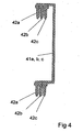
- Another embodiment of the conduit connector 40 is shown in a side view in Fig. 4.
- the connection contact pieces 42a, 42b and 42c belonging to the different phase rails 41a, 41b and 41c are offset in the direction transverse to the longitudinal extent of the phase rail block 43 from one another.
- the sockets 13 are then arranged offset on the upper narrow side 23 of the base housing 20 in parallel in planes parallel to the rear wall 11 of the house distribution box 10 so that the electrical contact by vertically inserting the terminal contact pieces 42a, 42b and 42c in the sockets 13th happens.
- the insertion of the line connector 40 in the space between the rear wall 11 and the first and second base housings 20 and 30 after the pre-assembly of the house distribution box 10 is carried out in the manner already described above.
Landscapes
- Engineering & Computer Science (AREA)
- Power Engineering (AREA)
- Connector Housings Or Holding Contact Members (AREA)
- Patch Boards (AREA)
Description
- Fig 1
- eine perspektivische Ansicht eines Hausverteilerkastens mit darin eingebauter Verteilvorrichtung,
- Fig 2
- die Vorderansicht einer erfindungsgemäßen Ausführungsform des Leitungsverbinders,
- Fig 3
- eine Seitenansicht des Leitungsverbinders gemäß Schnittlinie III der Fig 2,
- Fig 4
- die Seitenansicht einer weiteren Ausgestaltungsform des Leitungsverbinders.
Eine weitere Ausführungsform des Leitungsverbinders 40 ist in einer Seitenansicht in Fig. 4 dargestellt. Hierbei sind die zu den unterschiedlichen Phasenschienen 41a, 41b und 41c gehörenden Anschlußkontaktstücke 42a, 42b und 42c in Richtung quer zur Längserstreckung des Phasenschienenblocks 43 gegeneinander versetzt angeordnet. Bei dieser Ausführungsform sind dann auch die Steckbuchsen 13 an der oberen Schmalseite 23 des Basisgehäuses 20 in entsprechend in Ebenen parallel zur Rückwand 11 des Hausverteilerkastens 10 versetzt angeordnet, so daß die elektrische Kontaktierung durch vertikales Einführen der Anschlußkontaktstücke 42a, 42b und 42c in die Steckbuchsen 13 geschieht. Das Einführen des Leitungsverbinders 40 in den Zwischenraum zwischen Rückwand 11 und den ersten und zweiten Basisgehäusen 20 und 30 nach erfolgter Vormontage des Hausverteilerkastens 10 erfolgt in der oben bereits beschriebenen Art und Weise.
Claims (10)
- In eine Installationsanlage, vorzugsweise einen Hausverteilerkasten (10) einbaubare Anschlußvorrichtung oder Verteilvorrichtung für elektrische Installationsgeräte, insbesondere für Leitungsschutzschalter, Energiemodule u. dgl., mit einem ersten Basisgehäuse (20), in dem wenigstens eine erste Sammelschiene (21) untergebracht und an dem eine erste Normprofiltragschiene, vorzugsweise eine Hutprofilschiehe (22), angebracht sind, und wenigstens einem weiteren zweiten Basisgehäuse (30), das in einer Ebene parallel zur Rückwand (11) des Hausverteilerkastens (10) unter oder über dem ersten Basisgehäuse (20) liegt, in dem wenigstens eine zweite Sammelschiene (31) untergebracht und an dem eine zweite Normprofiltragschiene, vorzugsweise eine Hutprofilschiene (32), angebracht sind, wobei die Installationsgeräte auf die Normprofiltragschienen aufrastbar und an den Installationsgeräten Anschlußkontaktstücke (42a,42b,42c) vorgesehen sind, die beim Aufschnappen mit der wenigstens einen ersten oder zweiten Sammelschiene (21,31) in dem Bereich zwischen der Unterkante des Basisgehäuses und der Normprofiltragschiene in elektrische Kontaktierung bringbar sind, sowie mit wenigstens einem elektrischen Leitungsverbinder (40), mit dem die wenigstens erste Sammelschiene (21) und die wenigstens zweite Sammelschiene (31) elektrisch leitend verbindbar sind, dadurch gekennzeichnet, daß der Leitungsverbinder (40) in dem Zwischenraum zwischen Basisgehause (20,30) und Rückwand (11) des Hausverteilerkastens (10) angeordnet ist, daß an beiden Enden des Leitungsverbinders (40) Anschlußkontaktstucke (42a,42b,42c) vorgesehen sind und daß an der Sammelschiene an geeigneter Stelle Gegenkontaktstücke vorgesehen sind, die mit den Anschlußkontaktsctücken (42a,42b,42c) des Leitungsverbinders (40) zusammenarbeiten.
- Vorrichtung nach Anspruch 1, dadurch gekennzeichnet, daß der Leitungsverbinder (40) als Phasenschienenblock (43) mit einer oder mehreren gegeneinander isolierten und in ihrer Längserstreckungsrichtung parallel zueinander angeordneten Phasenschienen (41a,41b,41c) ausgebildet ist.
- Vorrichtung nach Anspruch 2, dadurch gekennzeichnet, daß die an der Sammelschiene (21,31) vorgesehenen Gegenkontaktstücke als an der Oberkante des Basisgehäuses (20) angebrachte Steckbuchsen (13) ausgeführt sind.
- Vorrichtung nach Anspruch 3, dadurch gekennzeichnet, daß jede Phasenschiene (41a,41b,41c) an ihrem oberen und unteren Ende L-förmige Anformungen (44) aufweisen deren als Anschlußkontaktstücke (42a,42b,42c) dienende freie Schenkel (45) in einer gemeinsamen Linie parallel zur Längserstreckung der Phasenschiene (41a,41b,41c) liegen und in die gleiche Richtung zeigen, und deren feste Schenkel quer zur Längserstreckung der Phasenschiene (41a,41b,41c) verlaufen.
- Vorrichtung nach Anspruch 4, dadurch gekennzeichnet, daß die Anschlußkontaktstücke (42a,42b,42c) aller Phasenschienen (41a,41b,41c) in einer gemeinsamen Ebene parallel zur Längserstreckung der Phasenschienen liegen.
- Vorrichtung nach Anspruch 4, dadurch gekennzeichnet, daß die zu unterschiedlichen Phasenschienen (41a,41b,41c) gehörenden Anschlußkontaktstücke (42a,42b,42c) in Richtung quer zur Längserstreckung der Phasenschiene gegeneinander versetzt angeordnet sind.
- Vorrichtung nach Anspruch 4, dadurch gekennzeichnet, daß das Einführen der Anschlußstücke (42a,42b,42c) in die Gegenkontaktstücke in vertikaler Richtung erfolgt
- Vorrichtung nach einem der vorherigen Ansprüche, dadurch gekennzeichnet, daß die freien Endkanten der Anschlußstücke (42a,42b,42c) zum Zwecke des leichteren Einführens in die Gegenkontaktstücke mit Einführschrägen (48) versehen sind.
- Vorrichtung nach einem der vorherigen Ansprüche, dadurch gekennzeichnet, daß die Anschlußkontaktstucke (42a,42b,42c) zum wecke der sicheren elektrischen Trennung durch Ausklinkungen (47) voneinander isoiiert sind.
- Vorrichtung nach einem der vorherigen Ansprüche, dadurch gekennzeichnet, daß die Phasenschienen (41a,41b,41c) als Flachbandleiter ausgebildet sind.
Applications Claiming Priority (3)
| Application Number | Priority Date | Filing Date | Title |
|---|---|---|---|
| DE10204934 | 2002-02-07 | ||
| DE10204934A DE10204934A1 (de) | 2002-02-07 | 2002-02-07 | Anschluß- oder Verteilvorrichtung für elektrische Installationsgeräte |
| PCT/EP2003/000465 WO2003067725A1 (de) | 2002-02-07 | 2003-01-18 | Anschluss- oder verteilvorrichtung für elektrische installationsgeräte |
Publications (2)
| Publication Number | Publication Date |
|---|---|
| EP1472766A1 EP1472766A1 (de) | 2004-11-03 |
| EP1472766B1 true EP1472766B1 (de) | 2005-11-23 |
Family
ID=27674572
Family Applications (1)
| Application Number | Title | Priority Date | Filing Date |
|---|---|---|---|
| EP03737259A Expired - Lifetime EP1472766B1 (de) | 2002-02-07 | 2003-01-18 | Anschluss- oder verteilvorrichtung für elektrische installationsgeräte |
Country Status (4)
| Country | Link |
|---|---|
| US (1) | US7092244B2 (de) |
| EP (1) | EP1472766B1 (de) |
| DE (2) | DE10204934A1 (de) |
| WO (1) | WO2003067725A1 (de) |
Cited By (1)
| Publication number | Priority date | Publication date | Assignee | Title |
|---|---|---|---|---|
| CN105024285A (zh) * | 2015-07-10 | 2015-11-04 | 惠州市豪美氏智能电气有限公司 | 一种具有母线连接的配电盒导轨 |
Families Citing this family (7)
| Publication number | Priority date | Publication date | Assignee | Title |
|---|---|---|---|---|
| ITMI20050709A1 (it) * | 2005-04-20 | 2006-10-21 | Coepte S R L | Dispositivo per il supporto di componenti elettrici e di accessori di cablaggio ad elevata praticita' di impiego |
| FR2905531B1 (fr) * | 2006-08-30 | 2015-02-27 | Auxel | Repartiteur de courant. |
| FI124167B (fi) * | 2013-05-06 | 2014-04-15 | Kone Corp | Hissin ohjaustaulu sekä hissi |
| US10411421B2 (en) | 2017-05-10 | 2019-09-10 | Abb Schweiz Ag | Electrical distribution system and methods of assembling same |
| FR3135357A1 (fr) | 2022-05-09 | 2023-11-10 | Schneider Electric Industries Sas | Dispositif d’interconnexion et tableau électrique comprenant un tel dispositif |
| FR3135360A1 (fr) | 2022-05-09 | 2023-11-10 | Schneider Electric Industries Sas | Dispositif d’interconnexion et tableau électrique comprenant un tel dispositif |
| FR3135362A1 (fr) | 2022-05-09 | 2023-11-10 | Schneider Electric Industries Sas | Dispositif d’interconnexion et tableau électrique comprenant un tel dispositif |
Family Cites Families (8)
| Publication number | Priority date | Publication date | Assignee | Title |
|---|---|---|---|---|
| US3767977A (en) * | 1972-04-17 | 1973-10-23 | Ite Circuit Breaker Ltd | Electric distribution panel having extruded buses and contact stabs |
| CA2116008A1 (en) * | 1991-08-20 | 1993-03-04 | Peter William Bowen | Improvements relating to the mounting of circuit breakers |
| SE9303561L (sv) * | 1993-10-29 | 1995-04-30 | Gaaroe Elektriska Ab | Överkopplingsbygel samt sätt att tillverka en sådan |
| FR2735290B1 (fr) * | 1995-06-07 | 1997-07-18 | Schneider Electric Sa | Dispositif d'assemblage et de liaison electrique d'appareils modulaires tels des disjoncteurs ou analogues |
| US5640294A (en) * | 1995-10-25 | 1997-06-17 | General Electric Company | Automated circuit breaker support saddle assembly |
| US5721672A (en) * | 1996-05-10 | 1998-02-24 | General Signal Corporation | Core modules for a life safety system and structure for supporting such modules in a panel housing |
| FR2761569B1 (fr) * | 1997-03-27 | 1999-06-11 | Gino Faccin | Chassis de cablage electrique |
| FR2784813B1 (fr) * | 1998-10-19 | 2000-12-15 | Framatome Connectors Int | Rail de contact comprenant des douilles femelles frontales pour relier entre eux plusieurs rails de contact |
-
2002
- 2002-02-07 DE DE10204934A patent/DE10204934A1/de not_active Withdrawn
-
2003
- 2003-01-18 DE DE50301738T patent/DE50301738D1/de not_active Expired - Lifetime
- 2003-01-18 EP EP03737259A patent/EP1472766B1/de not_active Expired - Lifetime
- 2003-01-18 WO PCT/EP2003/000465 patent/WO2003067725A1/de not_active Ceased
- 2003-01-18 US US10/501,533 patent/US7092244B2/en not_active Expired - Fee Related
Cited By (1)
| Publication number | Priority date | Publication date | Assignee | Title |
|---|---|---|---|---|
| CN105024285A (zh) * | 2015-07-10 | 2015-11-04 | 惠州市豪美氏智能电气有限公司 | 一种具有母线连接的配电盒导轨 |
Also Published As
| Publication number | Publication date |
|---|---|
| DE50301738D1 (de) | 2005-12-29 |
| EP1472766A1 (de) | 2004-11-03 |
| DE10204934A1 (de) | 2003-09-04 |
| US20050117281A1 (en) | 2005-06-02 |
| WO2003067725A1 (de) | 2003-08-14 |
| US7092244B2 (en) | 2006-08-15 |
Similar Documents
| Publication | Publication Date | Title |
|---|---|---|
| EP2546856B1 (de) | Leiste für NH-Sicherungen | |
| EP0639877B1 (de) | Vorrichtung zum Zuführen elektrischer Energie zu wenigstens einem elektrischen Installationsgerät | |
| DE68903836T2 (de) | Verbrauchereinheiten. | |
| DE69713706T2 (de) | Trag- und Stromeinspeisungsvorrichtung für ein elektrisches Gerät | |
| DE4021824A1 (de) | Verteileranlage mit auf einem tragorgan aneinanderreihbaren elektrischen installationsgeraeten in schmalbauweise | |
| DE4013223C2 (de) | Netzeinspeiseklemme | |
| EP1472766B1 (de) | Anschluss- oder verteilvorrichtung für elektrische installationsgeräte | |
| DE3779676T2 (de) | Speise- oder ueberbrueckungsgeraet fuer nebeneinander stehende elektrische einrichtungen. | |
| DE19506056C2 (de) | Adapterplatte zur Anbringung an ein mehrphasiges Stromschienensystem | |
| DE102019126155A1 (de) | Stromschienenmodul und entsprechendes Anschlussmodul | |
| EP0466043B1 (de) | Verteileranlage mit wenigstens zwei untereinander angeordneten Reihen von elektrischen Installationsgeräten in Schmalbauweise | |
| EP0821454B1 (de) | Anschlussvorrichtung für elektrische Installationsgeräte | |
| DE19530659C1 (de) | Niederspannungs-Sammelschienensystem | |
| DE69603000T2 (de) | Elektrische Anschlussleiste | |
| DE10146503A1 (de) | Elektrische Installationsverteilung | |
| DE19751705C2 (de) | Verrasteter Einbaublock | |
| DE102005023452B4 (de) | Montage- und Verdrahtungssystem für elektrische Funktionsmodule, insbesondere für Schaltgeräte | |
| DE19748555C1 (de) | Schaltschrank | |
| DE29706564U1 (de) | Trageinrichtung für Stromschienen | |
| EP1251537B1 (de) | Sicherungslasttrennschalter in Leistenbauform | |
| DE202004011908U1 (de) | Überspannungsableiter-Anordnung mit einer als Bestandteil eines Gehäuses ausführbaren Trägerplatte | |
| EP1253610B1 (de) | Adapter für das Kontaktieren von Lasttrennschaltern auf Stromsammelschienen | |
| DE102017114360B4 (de) | Spannungversorgungsvorrichtung für wenigstens ein aktives Zusatzgerät an einem Zählerplatz mit einem Sammelschienensystem sowie Verteilerschrank enthaltend eine solche Spannungsversorgungsvorrichtung | |
| DE10216371A1 (de) | Hilfsschalter | |
| EP0857364B1 (de) | Einspeisekasten |
Legal Events
| Date | Code | Title | Description |
|---|---|---|---|
| PUAI | Public reference made under article 153(3) epc to a published international application that has entered the european phase |
Free format text: ORIGINAL CODE: 0009012 |
|
| 17P | Request for examination filed |
Effective date: 20040609 |
|
| AK | Designated contracting states |
Kind code of ref document: A1 Designated state(s): AT BE BG CH CY CZ DE DK EE ES FI FR GB GR HU IE IT LI LU MC NL PT SE SI SK TR |
|
| GRAP | Despatch of communication of intention to grant a patent |
Free format text: ORIGINAL CODE: EPIDOSNIGR1 |
|
| GRAS | Grant fee paid |
Free format text: ORIGINAL CODE: EPIDOSNIGR3 |
|
| GRAA | (expected) grant |
Free format text: ORIGINAL CODE: 0009210 |
|
| AK | Designated contracting states |
Kind code of ref document: B1 Designated state(s): DE FR GB IT |
|
| REG | Reference to a national code |
Ref country code: GB Ref legal event code: FG4D Free format text: NOT ENGLISH |
|
| REF | Corresponds to: |
Ref document number: 50301738 Country of ref document: DE Date of ref document: 20051229 Kind code of ref document: P |
|
| GBT | Gb: translation of ep patent filed (gb section 77(6)(a)/1977) |
Effective date: 20051221 |
|
| ET | Fr: translation filed | ||
| PLBE | No opposition filed within time limit |
Free format text: ORIGINAL CODE: 0009261 |
|
| STAA | Information on the status of an ep patent application or granted ep patent |
Free format text: STATUS: NO OPPOSITION FILED WITHIN TIME LIMIT |
|
| 26N | No opposition filed |
Effective date: 20060824 |
|
| PGFP | Annual fee paid to national office [announced via postgrant information from national office to epo] |
Ref country code: FR Payment date: 20100223 Year of fee payment: 8 Ref country code: IT Payment date: 20100125 Year of fee payment: 8 |
|
| PGFP | Annual fee paid to national office [announced via postgrant information from national office to epo] |
Ref country code: DE Payment date: 20100121 Year of fee payment: 8 Ref country code: GB Payment date: 20100121 Year of fee payment: 8 |
|
| GBPC | Gb: european patent ceased through non-payment of renewal fee |
Effective date: 20110118 |
|
| REG | Reference to a national code |
Ref country code: FR Ref legal event code: ST Effective date: 20110930 |
|
| PG25 | Lapsed in a contracting state [announced via postgrant information from national office to epo] |
Ref country code: FR Free format text: LAPSE BECAUSE OF NON-PAYMENT OF DUE FEES Effective date: 20110131 |
|
| PG25 | Lapsed in a contracting state [announced via postgrant information from national office to epo] |
Ref country code: GB Free format text: LAPSE BECAUSE OF NON-PAYMENT OF DUE FEES Effective date: 20110118 |
|
| PG25 | Lapsed in a contracting state [announced via postgrant information from national office to epo] |
Ref country code: IT Free format text: LAPSE BECAUSE OF NON-PAYMENT OF DUE FEES Effective date: 20110118 |
|
| REG | Reference to a national code |
Ref country code: DE Ref legal event code: R119 Ref document number: 50301738 Country of ref document: DE Effective date: 20110802 |
|
| PG25 | Lapsed in a contracting state [announced via postgrant information from national office to epo] |
Ref country code: DE Free format text: LAPSE BECAUSE OF NON-PAYMENT OF DUE FEES Effective date: 20110802 |