EP1472766B1 - Connecting or distributing device for electrical installation equipment - Google Patents
Connecting or distributing device for electrical installation equipment Download PDFInfo
- Publication number
- EP1472766B1 EP1472766B1 EP03737259A EP03737259A EP1472766B1 EP 1472766 B1 EP1472766 B1 EP 1472766B1 EP 03737259 A EP03737259 A EP 03737259A EP 03737259 A EP03737259 A EP 03737259A EP 1472766 B1 EP1472766 B1 EP 1472766B1
- Authority
- EP
- European Patent Office
- Prior art keywords
- contact pieces
- phase
- base housing
- rail
- busbar
- Prior art date
- Legal status (The legal status is an assumption and is not a legal conclusion. Google has not performed a legal analysis and makes no representation as to the accuracy of the status listed.)
- Expired - Fee Related
Links
Images


Classifications
-
- H—ELECTRICITY
- H02—GENERATION; CONVERSION OR DISTRIBUTION OF ELECTRIC POWER
- H02B—BOARDS, SUBSTATIONS OR SWITCHING ARRANGEMENTS FOR THE SUPPLY OR DISTRIBUTION OF ELECTRIC POWER
- H02B1/00—Frameworks, boards, panels, desks, casings; Details of substations or switching arrangements
- H02B1/20—Bus-bar or other wiring layouts, e.g. in cubicles, in switchyards
- H02B1/205—Bus-bar or other wiring layouts, e.g. in cubicles, in switchyards for connecting electrical apparatus mounted side by side on a rail
Definitions
- the invention relates to a in an installation system, preferably a house distribution box installable connection device or distributor device for electrical Installation devices according to the preamble of claim 1 (see EP-A-1003258).
- the object of the invention is to provide a connection or distribution device for electrical Installation devices of the type mentioned above, in which the disadvantages of known devices are avoided.
- the line connector extends in the intermediate space between Base housing and rear wall of the house distribution box. At both ends of the Line connector terminal contacts are provided, and on the busbar are provided at a suitable location counter contact pieces with the Terminal contact pieces of the line connector can be brought into engagement.
- the line connector can be used as a phase rail block with one or more mutually insulated and parallel to each other in their longitudinal direction be arranged arranged phase rails.
- the at the busbar provided counter contact pieces than at the upper edge of the base housing mounted sockets executed.
- the insertion of the fittings in the Counter contact pieces is advantageously carried out in the vertical direction.
- each phase rail has their upper and lower end L-shaped projections, the free legs as Terminal contact pieces serve, in a common line parallel to the longitudinal extent lie on the phase rail and point in the same direction.
- the solid Legs of the L-shaped projections extend transversely to the longitudinal extent of Phase rail.
- the free end edges of the connecting pieces with insertion bevels be provided.
- the assembly of the connection and distribution device is considerably easier.
- FIG. 1 shows the perspective Representation of a house distribution box 10 with the distribution device installed therein, consisting of a first base housing 20, a second Base housing 30 and an electrical line connector 40.
- the house distribution box 10 has a rear wall 11; at the rear wall 11 opposite The front is open. In the rear area is in the house distribution box 10 a mounting frame 14 is used, on which the first and second Base housing 20 and 30 transversely to the longitudinal direction of the house distribution box 10 are attached.
- a first bus bar 21 is in the lower part housed, the electrical contacts 12 for receiving the contact pieces the installation equipment has.
- a first hat profile rail 22 is attached, which is for receiving the. Electrical installation equipment serves.
- roof-shaped, conically shaped formations 15 and intermediate conical recesses 16 mounted in which appropriate projections can intervene in the electrical installation equipment and through which the electrical installation devices are routed.
- three sockets 13 are provided with the the three terminal contact pieces 42a, 42b and 42c of the electrical line connector 40 are engageable.
- the second base housing 30 has the same structure as the first base housing, Accordingly, the vibrationsziffem 31, the second busbar 32, the second hat profile rail, 33 the upper narrow side of the second base housing. At the upper narrow side 33 of the second base housing 30 are also three sockets 13 provided. The second base housing 30 is in the house distribution box 10th mounted below the first base housing 20.
- the electrical lead connector 40 is, as shown in Fig. 1, in the Gap between the two base housings 20 and 30 and the rear wall 11th of the house distribution box 10 attached. It consists of a phase rail block 43, which at its upper and lower ends in each case three electrically from each other has isolated L-shaped projections 44, whose as terminal contact pieces serving free legs 45 in a common line parallel to the longitudinal extent of the phase rail block 43 and point in the same direction, whereas the fixed legs 46 transverse to the longitudinal extent of the phase rail block run.
- the insertion of the terminal contact pieces 42a, 42b and 42c in the Sockets 13 is done in the vertical direction, as indicated by the directional arrow in FIG. 1 indicated.
- the electrical line connector 40 even after the preassembly of the house distribution box 10, that is, after the two base housings 20 and 30 were mounted on the mounting frame 14, still can be used. He is placed in such a position that the upper End of the line connector 40 a little below the lower edge of the first Base housing 20 is located, then tilted slightly towards the rear wall 11 and so from bottom up in the space between the rear wall 11 and the Base housings 20 and 30 is introduced, that the molded at the upper end L-shaped Moldings 44 slide behind the first base housing 20 through and the formed at the lower end L-shaped projections before the second Base housing 30 are guided along.
- a preferred embodiment of the electrical line connector 40 is shown in FIG described in more detail. It is designed as a phase rail block 43 with three against each other isolated and parallel to each other in their longitudinal direction arranged phase rails 41a, 41b and 41c.
- the phase rails can in Particularly advantageous embodiment designed as a ribbon conductor.
- the bottom free end edges of the terminal contact pieces 42a, 42b and 42c are with Insertion bevels 48 provided so that the insertion into the sockets 13 facilitates becomes.
- Insertion bevels 48 provided so that the insertion into the sockets 13 facilitates becomes.
- the terminal contact pieces 42a, 42b and 42c against each other still insulated by notches 47 are the terminal contact pieces 42a, 42b and 42c against each other still insulated by notches 47.
- FIG. 3 shows a side view of the line connector 40 according to the direction of the arrow III.
- the free legs 45 of the L-shaped projections 44 attached to the top and bottom phase rails and thus also the terminal contact pieces 42a, 42b and 42c of the phase rail block lie in a common plane parallel to the longitudinal extent of the phase rails 41a, 41b, 41c.
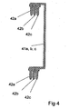
- Another embodiment of the conduit connector 40 is shown in a side view in Fig. 4.
- the connection contact pieces 42a, 42b and 42c belonging to the different phase rails 41a, 41b and 41c are offset in the direction transverse to the longitudinal extent of the phase rail block 43 from one another.
- the sockets 13 are then arranged offset on the upper narrow side 23 of the base housing 20 in parallel in planes parallel to the rear wall 11 of the house distribution box 10 so that the electrical contact by vertically inserting the terminal contact pieces 42a, 42b and 42c in the sockets 13th happens.
- the insertion of the line connector 40 in the space between the rear wall 11 and the first and second base housings 20 and 30 after the pre-assembly of the house distribution box 10 is carried out in the manner already described above.
Description
Die Erfindung betrifft eine in eine Installationsanlage, vorzugsweise einen Hausverteilerkasten einbaubare Anschlußvorrichtung oder Verteilvorrichtung für elektrische Installationsgeräte gemäß dem Oberbegriff des Anspruches 1 (siehe EP-A-1003258).The invention relates to a in an installation system, preferably a house distribution box installable connection device or distributor device for electrical Installation devices according to the preamble of claim 1 (see EP-A-1003258).
Als Elektroinstallationsgeräte werden Leitungsschutzschalter, Fehlerstromschutzschalter, Energiemodule oder ähnliche Installationsgeräte bezeichnet. Die Firma ABB Stotz-Kontakt GmbH, Heidelberg, produziert und vertreibt unter dem Produktnamen "System Connect" solche Anschluß- und Verteilvorrichtungen. Diese sind beispielsweise in dem Produktkatalog "Niederspannungsmaterial" der ABB Stotz-Kontakt /Striebel & John Vertriebsgesellschaft mbH aus dem Jahr 2000 beschrieben. Bei diesen sind im Hausverteilerkasten die Sammelschienen in einem Basisgehäuse untergebracht, an dem eine Normprofilschiene, vorzugsweise eine Hutprofilschiene angebracht ist, welche zur Aufnahme der Elektroinstallationsgeräte dient und den über Energiemodule eingespeisten Strom über die Sammelschienen an die einzelnen Elektroinstallationsgeräte weiterleitet. Insbesondere sind Systeme bekannt, bei denen in einem Hausverteilerkasten mehr als ein solches Basisgehäuse angebracht sind. Dabei wird der Strom von einer zur nächsten Sammelschiene mittels Leitungsverbinder weitergeleitet. Bei dem bekannten System Connect erfolgt die Verbindung der Sammelschienen mit an den Schmal- oder Stimseiten des Basisgehäuses befindlichen Steckkontakten, in die der Leitungsverbinder in horizontaler Richtung hineingesteckt wird. Die Gesamteinbaubreite des Basisgehäuses erhöht sich dabei um die Breite des Leitungsverbinders, da der Leitungsverbinder seitlich neben dem Basisgehäuse entlang geführt ist. Außerdem ist ein nachträglicher Einbau oder Austausch des Leitungsverbinders im fertig montierten Verteilerkasten aufgrund der Platzverhältnisse bei diesem seitlichen Anbringen nicht möglich ist. As electrical installation devices are circuit breakers, residual current circuit breakers, Energy modules or similar installation equipment called. The company ABB Stotz-Kontakt GmbH, Heidelberg, produces and sells under the product name "System Connect" such connection and distribution devices. These are for example in the product catalog "Low Voltage Material" of ABB Stotz-Kontakt / Striebel & John Vertriebsgesellschaft mbH from the year 2000. at These are in the distribution box, the busbars in a base housing accommodated on which a standard rail, preferably a DIN rail is attached, which serves to accommodate the electrical installation equipment and the over Energy modules fed electricity via the busbars to the individual Electrical installation equipment forwards. In particular, systems are known in which in a house distribution box more than one such base housing are mounted. The current from one to the next busbar by means of line connector forwarded. In the known system Connect the connection of the Busbars with located on the narrow or end sides of the base housing Plug contacts into which the cable connector inserted in the horizontal direction becomes. The total installation width of the base housing is increased by the Width of the cable connector, as the cable connector laterally next to the base housing is guided along. In addition, an additional installation or replacement of the line connector in the fully assembled distribution box due to space in this lateral attachment is not possible.
Aufgabe der Erfindung ist es, eine Anschluß- oder Verteilvorrichtung für elektrische Installationsgeräte der eingangs genannten Art zu schaffen, bei der die Nachteile der bekannten Vorrichtungen vermieden werden.The object of the invention is to provide a connection or distribution device for electrical Installation devices of the type mentioned above, in which the disadvantages of known devices are avoided.
Diese Aufgabe wird erfindungsgemäß durch die kennzeichnenden Merkmale des Anspruches 1 gelöst.This object is achieved by the characterizing features of claim 1 solved.
Erfindungsgemäß verläuft der Leitungsverbinder in dem Zwischenraum zwischen Basisgehäuse und Rückwand des Hausverteilerkastens. An beiden Enden des Leitungsverbinders sind Anschlußkontaktstücke vorgesehen, und an der Sammelschiene sind an geeigneter Stelle Gegenkontaktstücke vorgesehen, die mit den Anschlußkontaktstücken des Leitungsverbinders in Eingriff bringbar sind.According to the invention, the line connector extends in the intermediate space between Base housing and rear wall of the house distribution box. At both ends of the Line connector terminal contacts are provided, and on the busbar are provided at a suitable location counter contact pieces with the Terminal contact pieces of the line connector can be brought into engagement.
Der Leitungsverbinder kann dabei als Phasenschienenblock mit einer oder mehreren gegeneinander isolierten und in ihrer Längserstreckungsrichtung parallel zueinander angeordneten Phasenschienen ausgebildet sein.The line connector can be used as a phase rail block with one or more mutually insulated and parallel to each other in their longitudinal direction be arranged arranged phase rails.
Vorteil dieser Anordnung ist, daß die Einbaubreite des Basisgehäuses in den Hausverteilerkasten durch den Leitungsverbinder nun nicht mehr vergrößert wird.Advantage of this arrangement is that the installation width of the base housing in the House distribution box is no longer enlarged by the line connector.
In einer besonders vorteilhaften Ausgestaltung der Erfindung sind die an der Sammelschiene vorgesehenen Gegenkontaktstücke als an der Oberkante des Basisgehäuses angebrachte Steckbuchsen ausgeführt. Das Einführen der Anschlußstücke in die Gegenkontaktstücke erfolgt dabei vorteilhafterweise in vertikaler Richtung.In a particularly advantageous embodiment of the invention, the at the busbar provided counter contact pieces than at the upper edge of the base housing mounted sockets executed. The insertion of the fittings in the Counter contact pieces is advantageously carried out in the vertical direction.
Gemäß einer weiteren Ausgestaltung der Erfindung besitzt jede Phasenschiene an ihrem oberen und unteren Ende L-förmige Anformungen, deren freie Schenkel als Anschlußkontaktstücke dienen, in einer gemeinsamen Linie parallel zur Längserstreckung der Phasenschiene liegen und in die gleiche Richtung zeigen. Die festen Schenkel der L-förmigen Anformungen verlaufen quer zur Längserstreckung der Phasenschiene.According to a further embodiment of the invention, each phase rail has their upper and lower end L-shaped projections, the free legs as Terminal contact pieces serve, in a common line parallel to the longitudinal extent lie on the phase rail and point in the same direction. The solid Legs of the L-shaped projections extend transversely to the longitudinal extent of Phase rail.
Durch diese Ausgestaltung wird bewirkt, daß die Verbindungsebene der Leitungsverbinder versetzt zur Steckebene der Anschlußkontaktstücke verläuft. Dies ermöglicht ein besonders einfaches auch nachträgliches Einbauen oder Austauschen des Leitungsverbinders im fertig montierten Hausverteilerkasten.This configuration causes the connection plane of the line connector offset from the insertion plane of the terminal contact pieces runs. this makes possible a particularly simple and subsequent installation or replacement of the Line connector in the fully assembled house distribution box.
Damit beim Einstecken der Anschlußkontaktstücke in die Steckbuchsen keine zu hohe Steckkraft aufgewendet werden muß, können gemäß einer weiteren vorteilhaften Ausgestaltung der Erfindung die freien Endkanten der Anschlußstücke mit Einführschrägen versehen sein. Die Montage der Anschluß- und Verteilvorrichtung wird dadurch erheblich erleichtert.So that when inserting the terminal contact pieces in the sockets not too high Insertion force must be spent, according to another advantageous Embodiment of the invention, the free end edges of the connecting pieces with insertion bevels be provided. The assembly of the connection and distribution device is considerably easier.
Weitere vorteilhafte Ausgestaltungen und Verbesserungen der Erfindung sind den weiteren Unteransprüchen zu entnehmen.Further advantageous embodiments and improvements of the invention are the to remove further subclaims.
Anhand der Zeichnungen, in denen einige Ausführungsbeispiele der Erfindung dargestellt sind, sollen die Erfindung sowie weitere vorteilhafte Ausgestaltungen und Verbesserungen der Erfindung näher erläutert und beschrieben werden.Reference to the drawings, in which some embodiments of the invention are shown, the invention and further advantageous embodiments and Improvements of the invention are explained and described in more detail.
Es zeigen:
- Fig 1
- eine perspektivische Ansicht eines Hausverteilerkastens mit darin eingebauter Verteilvorrichtung,
- Fig 2
- die Vorderansicht einer erfindungsgemäßen Ausführungsform des Leitungsverbinders,
- Fig 3
- eine Seitenansicht des Leitungsverbinders gemäß Schnittlinie III der Fig 2,
- Fig 4
- die Seitenansicht einer weiteren Ausgestaltungsform des Leitungsverbinders.
- Fig. 1
- a perspective view of a house distribution box with built-in distribution device,
- Fig. 2
- the front view of an embodiment of the conduit connector according to the invention,
- Fig. 3
- a side view of the line connector according to section line III of Figure 2,
- Fig. 4
- the side view of another embodiment of the line connector.
Es sei nun Bezug genommen auf die Fig. 1. Diese zeigt die perspektivische
Darstellung eines Hausverteilerkastens 10 mit der darin eingebauten Verteilvorrichtung,
bestehend aus einem ersten Basisgehäuse 20, einem zweiten
Basisgehäuse 30 und einem elektrischen Leitungsverbinder 40. Der Hausverteilerkasten
10 besitzt eine Rückwand 11; an der der Rückwand 11 gegenüberliegenden
Vorderseite ist er offen. Im rückwärtigen Bereich ist in den Hausverteilerkasten
10 ein Montagerahmen 14 eingesetzt, an dem das erste und zweite
Basisgehäuse 20 und 30 quer zur Längserstreckungsrichtung des Hausverteilerkastens
10 befestigt sind. Reference is now made to FIG. 1. This shows the perspective
Representation of a
In dem ersten Basisgehäuse 20 ist im unteren Teil eine erste Sammelschiene 21
untergebracht, die elektrische Kontaktierungen 12 zur Aufnahme der Kontaktstücke
der Installationsgeräte aufweist. Im mittleren Bereich des ersten Basisgehäuses 20 ist
eine erste Hutprofilschiene 22 angebracht, die zur Aufnahme der. Elektroinstallationsgeräte
dient. In der im oberen Teil der der Rückwand 11 abgewandten Seitenfläche
des ersten Basisgehäuses 20 sind dachförmige, konisch ausgebildete Ausformungen
15 und dazwischenliegende konische Ausnehmungen 16 angebracht, in welche
entsprechende Vorsprünge in den Elektroinstallationsgeräten eingreifen können und
durch welche die Elektroinstallationsgeräte geführt werden. An der oberen Schmalseite
23 des ersten Basisgehäuses 20 sind drei Steckbuchsen 13 vorgesehen, die mit
den drei Anschlußkontaktstücken 42a, 42b und 42c des elektrischen Leitungsverbinders
40 in Eingriff bringbar sind.In the
Das zweite Basisgehäuse 30 ist identisch aufgebaut wie das erste Basisgehäuse,
entsprechend bezeichnen die Bezugsziffem 31 die zweite Sammelschiene, 32 die
zweite Hutprofilschiene, 33 die obere Schmalseite des zweiten Basisgehäuses. An der
oberen Schmalseite 33 des zweiten Basisgehäuses 30 sind ebenfalls drei Steckbuchsen
13 vorgesehen. Das zweite Basisgehäuse 30 ist im Hausverteilerkasten 10
unterhalb des ersten Basisgehäuses 20 angebracht.The
Der elektrische Leitungsverbinder 40 ist, wie in Fig. 1 ersichtlich, in dem
Zwischenraum zwischen den beiden Basisgehäusen 20 und 30 und der Rückwand 11
des Hausverteilerkastens 10 angebracht. Er besteht aus einem Phasenschienenblock
43, welcher an seinen oberen und unteren Enden jeweils drei elektrisch voneinander
isolierte L-förmige Anformungen 44 besitzt, deren als Anschlußkontaktstücke
dienende freie Schenkel 45 in einer gemeinsamen Linie parallel zur Längserstreckung
des Phasenschienenblocks 43 liegen und in die gleiche Richtung zeigen, wohingegen
die festen Schenkel 46 quer zur Längserstreckung des Phasenschienenblocks
verlaufen. Das Einführen der Anschlußkontaktstücke 42a, 42b und 42c in die
Steckbuchsen 13 geschieht in vertikaler Richtung, wie durch den Richtungspfeil in Fig.
1 angegeben. Besonders vorteilhaft dabei ist, daß der elektrische Leitungsverbinder
40 auch nach erfolgter Vormontage des Hausverteilerkastens 10, d.h., nachdem die
beiden Basisgehäuse 20 und 30 auf dem Montagerahmen 14 befestigt wurden, noch
eingesetzt werden kann. Er wird dazu in eine solche Position gebracht, daß das obere
Ende des Leitungsverbinders 40 ein wenig unterhalb der unteren Kante des ersten
Basisgehäuses 20 sich befindet, dann leicht zur Rückwand 11 hin gekippt und so von
unten nach oben in den Zwischenraum zwischen der Rückwand 11 und den
Basisgehäusen 20 und 30 eingeführt wird, daß die am oberen Ende angeformten L-förmigen
Anformungen 44 hinter dem ersten Basisgehäuse 20 hindurch gleiten und
die am unteren Ende angeformten L-förmigen Anformungen vor dem zweiten
Basisgehäuse 30 entlang geführt werden.The
Eine bevorzugte Ausführungsform des elektrischen Leitungsverbinders 40 ist in Fig. 2
näher beschrieben. Er ist ausgeführt als Phasenschienenblock 43 mit drei gegeneinander
isolierten und in ihrer Längserstreckungsrichtung parallel zueinander
angeordneten Phasenschienen 41a, 41 b und 41c. Die Phasenschienen können in
besonders vorteilhafter Ausgestaltung als Flachbandleiter ausgeführt sein. Die
unteren freien Endkanten der Anschlußkontaktstücke 42a, 42b und 42c sind mit
Einführschrägen 48 versehen, damit das Einführen in die Steckbuchsen 13 erleichtert
wird. Zum Zwecke einer sicheren elektrischen Trennung sind die Anschlusskontaktstücke
42a, 42b und 42c gegeneinander noch durch Ausklinkungen 47 isoliert.A preferred embodiment of the
Fig. 3 zeigt eine Seitenansicht des Leitungsverbinders 40 gemäß der Pfeilrichtung III.
Die freien Schenkel 45 der an den Phasenschienen oben und unten angebrachten L-förmigen
Anformungen 44 und damit auch die Anschlußkontaktstücke 42a, 42b und
42c des Phasenschienenblocks liegen in einer gemeinsamen Ebene parallel zur
Längserstreckung der Phasenschienen 41a, 41b, 41c.
Eine weitere Ausführungsform des Leitungsverbinders 40 ist in einer Seitenansicht in
Fig. 4 dargestellt. Hierbei sind die zu den unterschiedlichen Phasenschienen 41a, 41b
und 41c gehörenden Anschlußkontaktstücke 42a, 42b und 42c in Richtung quer zur
Längserstreckung des Phasenschienenblocks 43 gegeneinander versetzt angeordnet.
Bei dieser Ausführungsform sind dann auch die Steckbuchsen 13 an der oberen
Schmalseite 23 des Basisgehäuses 20 in entsprechend in Ebenen parallel zur
Rückwand 11 des Hausverteilerkastens 10 versetzt angeordnet, so daß die
elektrische Kontaktierung durch vertikales Einführen der Anschlußkontaktstücke 42a,
42b und 42c in die Steckbuchsen 13 geschieht. Das Einführen des Leitungsverbinders
40 in den Zwischenraum zwischen Rückwand 11 und den ersten und zweiten
Basisgehäusen 20 und 30 nach erfolgter Vormontage des Hausverteilerkastens 10
erfolgt in der oben bereits beschriebenen Art und Weise.3 shows a side view of the
Another embodiment of the
Claims (10)
- Connecting device or distributing device, which can be installed in an installation system, preferably a domestic distribution box (10), for electrical installation equipment, in particular for circuit breakers, energy modules etc., having a first base housing (20), in which at least one first busbar (21) is accommodated and on which a first standard mounting rail, preferably a top-hat rail (22), is fitted, and at least one further second base housing (30) which lies on a plane parallel to the rear wall (11) of the domestic distribution box (10) below or above the first base housing (20) in which at least one second busbar (31) is accommodated and on which a second standard mounting rail, preferably a top-hat rail (32), is fitted, it being possible for the installation equipment to be latched onto the standard mounting rails, and connection contact pieces (42a, 42b, 42c) being provided on the installation equipment which, when snapped on, can be brought into electrical contact with the at least one first or second busbar (21, 31) in the region between the lower edge of.the base housing and the standard mounting rail, and having at least one electrical line connector (40), with which the at least first busbar (21) and the at least second busbar (31) can be electrically conductively connected, characterized in that the line connector (40) is arranged in the intermediate' space between the base housing (20, 30) and the rear wall (11) of the domestic distribution box (10), in that connection contact pieces (42a, 42b, 42c) are provided at both ends of the line connector (40), and in that opposing contact pieces are provided at a suitable point on the busbar, said opposing contact pieces interacting with the connection contact pieces (42a, 42b, 42c) of the line connector (40).
- Device according to Claim 1, characterized in that the line connector (40) is in the form of a phase rail block (43) having one or more phase rails (41a, 41b, 41c) which are insulated from one another and are arranged parallel to one another in the direction of their longitudinal extent.
- Device according to Claim 2, characterized in that the opposing contact pieces provided on the busbar (21, 31) are in the form of plug sockets (13) fitted on the upper edge of the base housing (20).
- Device according to Claim 3, characterized in that each phase rail (41a, 41b, 41c) has L-shaped integrally formed sections (44) at its upper and lower end, the free limbs (45) of said integrally formed sections (44) acting as connection contact pieces (42a, 42b, 42c), lying on a common line parallel to the longitudinal extent of the phase rail (41a, 41b, 41c) and pointing in the same direction, and the fixed limbs of said integrally formed sections (44) extending transversely with respect to the longitudinal extent of the phase rail (41a, 41b, 41c).
- Device according to Claim 4, characterized in that the connection contact pieces (42a, 42b, 42c) of all of the phase rails (41a, 41b, 41c) lie on a common plane parallel to the longitudinal extent of the phase rails.
- Device according to Claim 4, characterized in that the connection contact pieces (42a, 42b, 42c) associated with different phase rails (41a, 41b, 41c) are arranged such that they are offset with respect to one another in a direction transverse with respect to the longitudinal extent of the phase rail.
- Device according to Claim 4, characterized in that the connection pieces (42a, 42b, 42c) are inserted into the opposing contact pieces in the vertical direction.
- Device according to one of the preceding claims, characterized in that the free end edges of the connection pieces (42a, 42b, 42c) are provided with insertion bevels (48) in order to make it easier to insert them in the opposing contact pieces.
- Device according to one of the preceding claims, characterized in that the connection contact pieces (42a, 42b, 42c) are insulated from one another by means of notches (47) for reliable electrical isolation purposes.
- Device according to one of the preceding claims, characterized in that the phase rails (41a, 41b, 41c) are in the form of flat ribbon conductors.
Applications Claiming Priority (3)
| Application Number | Priority Date | Filing Date | Title |
|---|---|---|---|
| DE10204934A DE10204934A1 (en) | 2002-02-07 | 2002-02-07 | Connection or distribution device for electrical installation devices |
| DE10204934 | 2002-02-07 | ||
| PCT/EP2003/000465 WO2003067725A1 (en) | 2002-02-07 | 2003-01-18 | Connecting or distributing device for electrical installation equipment |
Publications (2)
| Publication Number | Publication Date |
|---|---|
| EP1472766A1 EP1472766A1 (en) | 2004-11-03 |
| EP1472766B1 true EP1472766B1 (en) | 2005-11-23 |
Family
ID=27674572
Family Applications (1)
| Application Number | Title | Priority Date | Filing Date |
|---|---|---|---|
| EP03737259A Expired - Fee Related EP1472766B1 (en) | 2002-02-07 | 2003-01-18 | Connecting or distributing device for electrical installation equipment |
Country Status (4)
| Country | Link |
|---|---|
| US (1) | US7092244B2 (en) |
| EP (1) | EP1472766B1 (en) |
| DE (2) | DE10204934A1 (en) |
| WO (1) | WO2003067725A1 (en) |
Cited By (1)
| Publication number | Priority date | Publication date | Assignee | Title |
|---|---|---|---|---|
| CN105024285A (en) * | 2015-07-10 | 2015-11-04 | 惠州市豪美氏智能电气有限公司 | Distribution box guide rail having bus connection function |
Families Citing this family (7)
| Publication number | Priority date | Publication date | Assignee | Title |
|---|---|---|---|---|
| ITMI20050709A1 (en) * | 2005-04-20 | 2006-10-21 | Coepte S R L | DEVICE FOR SUPPORTING ELECTRICAL COMPONENTS AND WIRING ACCESSORIES WITH HIGH PRACTICAL USE |
| FR2905531B1 (en) * | 2006-08-30 | 2015-02-27 | Auxel | CURRENT DISTRIBUTOR. |
| FI124167B (en) * | 2013-05-06 | 2014-04-15 | Kone Corp | Control panel for elevator and elevator |
| US10411421B2 (en) | 2017-05-10 | 2019-09-10 | Abb Schweiz Ag | Electrical distribution system and methods of assembling same |
| FR3135357A1 (en) | 2022-05-09 | 2023-11-10 | Schneider Electric Industries Sas | Interconnection device and electrical panel comprising such a device |
| FR3135360A1 (en) | 2022-05-09 | 2023-11-10 | Schneider Electric Industries Sas | Interconnection device and electrical panel comprising such a device |
| FR3135362A1 (en) | 2022-05-09 | 2023-11-10 | Schneider Electric Industries Sas | Interconnection device and electrical panel comprising such a device |
Family Cites Families (8)
| Publication number | Priority date | Publication date | Assignee | Title |
|---|---|---|---|---|
| US3767977A (en) * | 1972-04-17 | 1973-10-23 | Ite Circuit Breaker Ltd | Electric distribution panel having extruded buses and contact stabs |
| AU668858B2 (en) * | 1991-08-20 | 1996-05-23 | Electrium Sales Limited | Improvements relating to the mounting of circuit breakers |
| SE9303561L (en) | 1993-10-29 | 1995-04-30 | Gaaroe Elektriska Ab | Switching bracket and way to manufacture one |
| FR2735290B1 (en) * | 1995-06-07 | 1997-07-18 | Schneider Electric Sa | ASSEMBLY AND ELECTRICAL CONNECTION DEVICE FOR MODULAR APPLIANCES SUCH AS CIRCUIT BREAKERS OR SIMILAR |
| US5640294A (en) * | 1995-10-25 | 1997-06-17 | General Electric Company | Automated circuit breaker support saddle assembly |
| US5721672A (en) * | 1996-05-10 | 1998-02-24 | General Signal Corporation | Core modules for a life safety system and structure for supporting such modules in a panel housing |
| FR2761569B1 (en) * | 1997-03-27 | 1999-06-11 | Gino Faccin | ELECTRIC WIRING CHASSIS |
| FR2784813B1 (en) | 1998-10-19 | 2000-12-15 | Framatome Connectors Int | CONTACT RAIL COMPRISING FRONT FEMALE SOCKETS FOR CONNECTING BETWEEN SEVERAL CONTACT RAILS |
-
2002
- 2002-02-07 DE DE10204934A patent/DE10204934A1/en not_active Withdrawn
-
2003
- 2003-01-18 US US10/501,533 patent/US7092244B2/en not_active Expired - Fee Related
- 2003-01-18 DE DE50301738T patent/DE50301738D1/en not_active Expired - Lifetime
- 2003-01-18 EP EP03737259A patent/EP1472766B1/en not_active Expired - Fee Related
- 2003-01-18 WO PCT/EP2003/000465 patent/WO2003067725A1/en active IP Right Grant
Cited By (1)
| Publication number | Priority date | Publication date | Assignee | Title |
|---|---|---|---|---|
| CN105024285A (en) * | 2015-07-10 | 2015-11-04 | 惠州市豪美氏智能电气有限公司 | Distribution box guide rail having bus connection function |
Also Published As
| Publication number | Publication date |
|---|---|
| US7092244B2 (en) | 2006-08-15 |
| DE50301738D1 (en) | 2005-12-29 |
| US20050117281A1 (en) | 2005-06-02 |
| DE10204934A1 (en) | 2003-09-04 |
| EP1472766A1 (en) | 2004-11-03 |
| WO2003067725A1 (en) | 2003-08-14 |
Similar Documents
| Publication | Publication Date | Title |
|---|---|---|
| EP2255410B1 (en) | Modular terminal, and modular terminal block | |
| EP2546856B1 (en) | Bar for NH fuses | |
| DE102016114070B3 (en) | Busbar connector and set of two complementary busbar connectors and metal troughs, each with a current-carrying profile incorporated therein | |
| DE3621268C2 (en) | Three-phase encapsulated, gas-insulated switchgear | |
| EP0639877B1 (en) | Device for supplying at least one electric installation appliance with electric energy | |
| DE19511350A1 (en) | Rail channel system of a low-voltage switchgear | |
| DE4021824A1 (en) | DISTRIBUTION SYSTEM WITH ELECTRICAL INSTALLATION DEVICES IN NARROW CONSTRUCTION ON A CARRIER | |
| EP1472766B1 (en) | Connecting or distributing device for electrical installation equipment | |
| DE4013223C2 (en) | Power supply terminal | |
| DE102019126155A1 (en) | Busbar module and corresponding connection module | |
| DE19506056C2 (en) | Adapter plate for attachment to a multi-phase track system | |
| DE2616525C2 (en) | Electrical installation distribution | |
| EP0821454B1 (en) | Connecting device for electrical installation apparatus | |
| DE19530659C1 (en) | Low voltage busbar system | |
| DE102005023452B4 (en) | Mounting and wiring system for electrical function modules, in particular for switching devices | |
| DE102004037083A1 (en) | Surge arrester arrangement with an executable as part of a housing support plate | |
| EP0466043B1 (en) | Distribution installation with at least two rows of electrical apparatus of a narrow type | |
| EP1587166B1 (en) | Repartition block | |
| DE10146503A1 (en) | Electrical installation distribution | |
| DE19751705C2 (en) | Locked mounting block | |
| DE19748555C1 (en) | Electrical switch apparatus cabinet | |
| DE102017114360B4 (en) | Voltage supply device for at least one active additional device at a meter station with a busbar system and distribution cabinet containing such a voltage supply device | |
| EP1251537B1 (en) | Load break switch of the strip type with fuses | |
| EP1351336A1 (en) | Connector module for plug-in installation system | |
| DE202004011908U1 (en) | Overvoltage disconnection device especially for low voltage supplies provides direct mechanical and electrical connection to a bus bar system |
Legal Events
| Date | Code | Title | Description |
|---|---|---|---|
| PUAI | Public reference made under article 153(3) epc to a published international application that has entered the european phase |
Free format text: ORIGINAL CODE: 0009012 |
|
| 17P | Request for examination filed |
Effective date: 20040609 |
|
| AK | Designated contracting states |
Kind code of ref document: A1 Designated state(s): AT BE BG CH CY CZ DE DK EE ES FI FR GB GR HU IE IT LI LU MC NL PT SE SI SK TR |
|
| GRAP | Despatch of communication of intention to grant a patent |
Free format text: ORIGINAL CODE: EPIDOSNIGR1 |
|
| GRAS | Grant fee paid |
Free format text: ORIGINAL CODE: EPIDOSNIGR3 |
|
| GRAA | (expected) grant |
Free format text: ORIGINAL CODE: 0009210 |
|
| AK | Designated contracting states |
Kind code of ref document: B1 Designated state(s): DE FR GB IT |
|
| REG | Reference to a national code |
Ref country code: GB Ref legal event code: FG4D Free format text: NOT ENGLISH |
|
| REF | Corresponds to: |
Ref document number: 50301738 Country of ref document: DE Date of ref document: 20051229 Kind code of ref document: P |
|
| GBT | Gb: translation of ep patent filed (gb section 77(6)(a)/1977) |
Effective date: 20051221 |
|
| ET | Fr: translation filed | ||
| PLBE | No opposition filed within time limit |
Free format text: ORIGINAL CODE: 0009261 |
|
| STAA | Information on the status of an ep patent application or granted ep patent |
Free format text: STATUS: NO OPPOSITION FILED WITHIN TIME LIMIT |
|
| 26N | No opposition filed |
Effective date: 20060824 |
|
| PGFP | Annual fee paid to national office [announced via postgrant information from national office to epo] |
Ref country code: FR Payment date: 20100223 Year of fee payment: 8 Ref country code: IT Payment date: 20100125 Year of fee payment: 8 |
|
| PGFP | Annual fee paid to national office [announced via postgrant information from national office to epo] |
Ref country code: DE Payment date: 20100121 Year of fee payment: 8 Ref country code: GB Payment date: 20100121 Year of fee payment: 8 |
|
| GBPC | Gb: european patent ceased through non-payment of renewal fee |
Effective date: 20110118 |
|
| REG | Reference to a national code |
Ref country code: FR Ref legal event code: ST Effective date: 20110930 |
|
| PG25 | Lapsed in a contracting state [announced via postgrant information from national office to epo] |
Ref country code: FR Free format text: LAPSE BECAUSE OF NON-PAYMENT OF DUE FEES Effective date: 20110131 |
|
| PG25 | Lapsed in a contracting state [announced via postgrant information from national office to epo] |
Ref country code: GB Free format text: LAPSE BECAUSE OF NON-PAYMENT OF DUE FEES Effective date: 20110118 |
|
| PG25 | Lapsed in a contracting state [announced via postgrant information from national office to epo] |
Ref country code: IT Free format text: LAPSE BECAUSE OF NON-PAYMENT OF DUE FEES Effective date: 20110118 |
|
| REG | Reference to a national code |
Ref country code: DE Ref legal event code: R119 Ref document number: 50301738 Country of ref document: DE Effective date: 20110802 |
|
| PG25 | Lapsed in a contracting state [announced via postgrant information from national office to epo] |
Ref country code: DE Free format text: LAPSE BECAUSE OF NON-PAYMENT OF DUE FEES Effective date: 20110802 |