EP3276432A1 - Untereinheit zur verkleidung einer uhr, armbanduhr oder eines schmuckstücks - Google Patents
Untereinheit zur verkleidung einer uhr, armbanduhr oder eines schmuckstücks Download PDFInfo
- Publication number
- EP3276432A1 EP3276432A1 EP16181139.3A EP16181139A EP3276432A1 EP 3276432 A1 EP3276432 A1 EP 3276432A1 EP 16181139 A EP16181139 A EP 16181139A EP 3276432 A1 EP3276432 A1 EP 3276432A1
- Authority
- EP
- European Patent Office
- Prior art keywords
- component
- ring
- subassembly
- relative
- rotation
- Prior art date
- Legal status (The legal status is an assumption and is not a legal conclusion. Google has not performed a legal analysis and makes no representation as to the accuracy of the status listed.)
- Granted
Links
- 239000010437 gem Substances 0.000 title claims abstract description 15
- 229910001751 gemstone Inorganic materials 0.000 title claims abstract description 11
- 238000005253 cladding Methods 0.000 claims description 19
- 230000000295 complement effect Effects 0.000 claims description 18
- 238000003780 insertion Methods 0.000 claims description 11
- 230000037431 insertion Effects 0.000 claims description 11
- 230000000284 resting effect Effects 0.000 claims 1
- 239000000463 material Substances 0.000 description 16
- 239000000919 ceramic Substances 0.000 description 9
- 238000007789 sealing Methods 0.000 description 8
- 230000006835 compression Effects 0.000 description 6
- 238000007906 compression Methods 0.000 description 6
- 229910052594 sapphire Inorganic materials 0.000 description 6
- 239000010980 sapphire Substances 0.000 description 6
- 229920006324 polyoxymethylene Polymers 0.000 description 5
- 230000008901 benefit Effects 0.000 description 4
- 230000000694 effects Effects 0.000 description 4
- 230000006870 function Effects 0.000 description 4
- 229910000808 amorphous metal alloy Inorganic materials 0.000 description 3
- 229920001971 elastomer Polymers 0.000 description 3
- 238000003754 machining Methods 0.000 description 3
- 238000012423 maintenance Methods 0.000 description 3
- 230000007246 mechanism Effects 0.000 description 3
- 239000004033 plastic Substances 0.000 description 3
- 229920003023 plastic Polymers 0.000 description 3
- 239000004433 Thermoplastic polyurethane Substances 0.000 description 2
- 230000003042 antagnostic effect Effects 0.000 description 2
- 238000010586 diagram Methods 0.000 description 2
- 239000013013 elastic material Substances 0.000 description 2
- 239000000806 elastomer Substances 0.000 description 2
- PCHJSUWPFVWCPO-UHFFFAOYSA-N gold Chemical compound [Au] PCHJSUWPFVWCPO-UHFFFAOYSA-N 0.000 description 2
- 239000010931 gold Substances 0.000 description 2
- 229910052737 gold Inorganic materials 0.000 description 2
- 238000005304 joining Methods 0.000 description 2
- 229910001338 liquidmetal Inorganic materials 0.000 description 2
- 238000004519 manufacturing process Methods 0.000 description 2
- 239000002184 metal Substances 0.000 description 2
- 229910052751 metal Inorganic materials 0.000 description 2
- 239000004417 polycarbonate Substances 0.000 description 2
- -1 polytetrafluoroethylene Polymers 0.000 description 2
- 229920001343 polytetrafluoroethylene Polymers 0.000 description 2
- 239000004810 polytetrafluoroethylene Substances 0.000 description 2
- 229920002635 polyurethane Polymers 0.000 description 2
- 239000004814 polyurethane Substances 0.000 description 2
- 229920000915 polyvinyl chloride Polymers 0.000 description 2
- 230000002441 reversible effect Effects 0.000 description 2
- 230000035807 sensation Effects 0.000 description 2
- 229910001220 stainless steel Inorganic materials 0.000 description 2
- 229920002725 thermoplastic elastomer Polymers 0.000 description 2
- 229920002803 thermoplastic polyurethane Polymers 0.000 description 2
- 230000002747 voluntary effect Effects 0.000 description 2
- 206010009696 Clumsiness Diseases 0.000 description 1
- 229920000271 Kevlar® Polymers 0.000 description 1
- 239000004677 Nylon Substances 0.000 description 1
- 229930040373 Paraformaldehyde Natural products 0.000 description 1
- 241000287107 Passer Species 0.000 description 1
- 230000009471 action Effects 0.000 description 1
- 229910045601 alloy Inorganic materials 0.000 description 1
- 239000000956 alloy Substances 0.000 description 1
- 239000007866 anti-wear additive Substances 0.000 description 1
- 230000003416 augmentation Effects 0.000 description 1
- 230000000903 blocking effect Effects 0.000 description 1
- 238000004140 cleaning Methods 0.000 description 1
- 230000001186 cumulative effect Effects 0.000 description 1
- 238000005034 decoration Methods 0.000 description 1
- 230000003247 decreasing effect Effects 0.000 description 1
- 238000013461 design Methods 0.000 description 1
- 230000009189 diving Effects 0.000 description 1
- 238000005553 drilling Methods 0.000 description 1
- 230000005489 elastic deformation Effects 0.000 description 1
- 235000021183 entrée Nutrition 0.000 description 1
- 239000000835 fiber Substances 0.000 description 1
- 229910052734 helium Inorganic materials 0.000 description 1
- 239000001307 helium Substances 0.000 description 1
- SWQJXJOGLNCZEY-UHFFFAOYSA-N helium atom Chemical compound [He] SWQJXJOGLNCZEY-UHFFFAOYSA-N 0.000 description 1
- 229910052500 inorganic mineral Inorganic materials 0.000 description 1
- 238000005461 lubrication Methods 0.000 description 1
- 229910001092 metal group alloy Inorganic materials 0.000 description 1
- 239000007769 metal material Substances 0.000 description 1
- 239000005300 metallic glass Substances 0.000 description 1
- 238000000034 method Methods 0.000 description 1
- 239000011707 mineral Substances 0.000 description 1
- 229920001778 nylon Polymers 0.000 description 1
- 230000002093 peripheral effect Effects 0.000 description 1
- 229920000515 polycarbonate Polymers 0.000 description 1
- 229920000642 polymer Polymers 0.000 description 1
- 229920001296 polysiloxane Polymers 0.000 description 1
- 230000000750 progressive effect Effects 0.000 description 1
- 238000012797 qualification Methods 0.000 description 1
- 230000008439 repair process Effects 0.000 description 1
- 238000010079 rubber tapping Methods 0.000 description 1
- 239000010935 stainless steel Substances 0.000 description 1
- 230000000007 visual effect Effects 0.000 description 1
Images

Classifications
-
- G—PHYSICS
- G04—HOROLOGY
- G04B—MECHANICALLY-DRIVEN CLOCKS OR WATCHES; MECHANICAL PARTS OF CLOCKS OR WATCHES IN GENERAL; TIME PIECES USING THE POSITION OF THE SUN, MOON OR STARS
- G04B37/00—Cases
- G04B37/0008—Cases for pocket watches and wrist watches
-
- G—PHYSICS
- G04—HOROLOGY
- G04B—MECHANICALLY-DRIVEN CLOCKS OR WATCHES; MECHANICAL PARTS OF CLOCKS OR WATCHES IN GENERAL; TIME PIECES USING THE POSITION OF THE SUN, MOON OR STARS
- G04B45/00—Time pieces of which the indicating means or cases provoke special effects, e.g. aesthetic effects
-
- A—HUMAN NECESSITIES
- A44—HABERDASHERY; JEWELLERY
- A44C—PERSONAL ADORNMENTS, e.g. JEWELLERY; COINS
- A44C25/00—Miscellaneous fancy ware for personal wear, e.g. pendants, crosses, crucifixes, charms
-
- A—HUMAN NECESSITIES
- A44—HABERDASHERY; JEWELLERY
- A44C—PERSONAL ADORNMENTS, e.g. JEWELLERY; COINS
- A44C27/00—Making jewellery or other personal adornments
-
- G—PHYSICS
- G04—HOROLOGY
- G04B—MECHANICALLY-DRIVEN CLOCKS OR WATCHES; MECHANICAL PARTS OF CLOCKS OR WATCHES IN GENERAL; TIME PIECES USING THE POSITION OF THE SUN, MOON OR STARS
- G04B19/00—Indicating the time by visual means
- G04B19/28—Adjustable guide marks or pointers for indicating determined points of time
- G04B19/283—Adjustable guide marks or pointers for indicating determined points of time on rotatable rings, i.e. bezel
- G04B19/286—Adjustable guide marks or pointers for indicating determined points of time on rotatable rings, i.e. bezel with locking means to prevent undesired rotations in both directions
-
- G—PHYSICS
- G04—HOROLOGY
- G04B—MECHANICALLY-DRIVEN CLOCKS OR WATCHES; MECHANICAL PARTS OF CLOCKS OR WATCHES IN GENERAL; TIME PIECES USING THE POSITION OF THE SUN, MOON OR STARS
- G04B37/00—Cases
-
- G—PHYSICS
- G04—HOROLOGY
- G04B—MECHANICALLY-DRIVEN CLOCKS OR WATCHES; MECHANICAL PARTS OF CLOCKS OR WATCHES IN GENERAL; TIME PIECES USING THE POSITION OF THE SUN, MOON OR STARS
- G04B37/00—Cases
- G04B37/08—Hermetic sealing of openings, joints, passages or slits
-
- G—PHYSICS
- G04—HOROLOGY
- G04B—MECHANICALLY-DRIVEN CLOCKS OR WATCHES; MECHANICAL PARTS OF CLOCKS OR WATCHES IN GENERAL; TIME PIECES USING THE POSITION OF THE SUN, MOON OR STARS
- G04B37/00—Cases
- G04B37/08—Hermetic sealing of openings, joints, passages or slits
- G04B37/084—Complete encasings for wrist or pocket watches without means for hermetic sealing of winding stem or crown
-
- G—PHYSICS
- G04—HOROLOGY
- G04B—MECHANICALLY-DRIVEN CLOCKS OR WATCHES; MECHANICAL PARTS OF CLOCKS OR WATCHES IN GENERAL; TIME PIECES USING THE POSITION OF THE SUN, MOON OR STARS
- G04B37/00—Cases
- G04B37/08—Hermetic sealing of openings, joints, passages or slits
- G04B37/11—Hermetic sealing of openings, joints, passages or slits of the back cover of pocket or wrist watches
-
- G—PHYSICS
- G04—HOROLOGY
- G04B—MECHANICALLY-DRIVEN CLOCKS OR WATCHES; MECHANICAL PARTS OF CLOCKS OR WATCHES IN GENERAL; TIME PIECES USING THE POSITION OF THE SUN, MOON OR STARS
- G04B47/00—Time-pieces combined with other articles which do not interfere with the running or the time-keeping of the time-piece
- G04B47/04—Time-pieces combined with other articles which do not interfere with the running or the time-keeping of the time-piece with attached ornaments or amusement apparatus
-
- G—PHYSICS
- G04—HOROLOGY
- G04B—MECHANICALLY-DRIVEN CLOCKS OR WATCHES; MECHANICAL PARTS OF CLOCKS OR WATCHES IN GENERAL; TIME PIECES USING THE POSITION OF THE SUN, MOON OR STARS
- G04B19/00—Indicating the time by visual means
-
- G—PHYSICS
- G04—HOROLOGY
- G04B—MECHANICALLY-DRIVEN CLOCKS OR WATCHES; MECHANICAL PARTS OF CLOCKS OR WATCHES IN GENERAL; TIME PIECES USING THE POSITION OF THE SUN, MOON OR STARS
- G04B47/00—Time-pieces combined with other articles which do not interfere with the running or the time-keeping of the time-piece
Definitions
- the invention relates to a subassembly, called cladding, for a timepiece or a watch or a jewel, comprising a first component having protruding edges of a first skirt alternated with first clearances, and a second component comprising wings projecting from a second skirt alternating with second clearances, arranged to occupy a first disassembled insertion position in which said first component and said second component have with respect to one another a first angular orientation, or for occupying an assembled and locked position in which said first component and said second component have relative to each other a second angular orientation different from said first angular orientation and are held axially by a bayonet fit between at least two said flanges and at least two said wings.
- the invention also relates to a timepiece, including a watch, including such a subassembly dressing.
- the invention also relates to a jewel comprising such a subset.
- the invention relates to the field of dressing watches, and the field of jewelry and jewelery.
- the cladding of watches and similar devices obeys many constraints, in particular sealing, robustness, appearance, and must be realized in order to prevent any unintentional disassembly resulting irreparably by an after-sales intervention for exchange of seals, cleaning, lubrication, even repair.
- Some dressing or control components must, again, be indexed angularly with respect to each other, for reference positions of origin reference, rest, or actuation, or to facilitate the reading of indications or graduations, or to ensure the continuity of left surfaces and / or decorations. This angular indexing is often difficult to achieve, in combination with a good tightening of the components and with a perfect sealing of the joints.
- the invention proposes to achieve a tight and secure assembly of cladding components with an easy to adjust angular indexing.
- the invention relates to a subassembly of cladding for a timepiece according to claim 1.
- the invention also relates to a timepiece comprising such a dressing subassembly.
- the invention also relates to a jewel comprising such a subset.
- the invention proposes to achieve a tight and secure assembly of cladding components with easy to adjust angular indexing, and in a guaranteed position, and this with a minimum number of components, and moderate manufacturing costs.
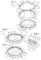
- the Figures 1 to 10 illustrate the nonlimiting example of the angular indexing of a background relative to a watchband.
- the invention relates to a covering subassembly 100 for a timepiece, and more particularly for a watch, or for a jewel, comprising a first component 1 comprising flanges 2 projecting from a first skirt 6 alternated with first clearances, and a second component 10 having wings 12 projecting from a second skirt 11 alternated with second clearances 13.
- the general denomination of "dressing" sub-assembly is used here as well for a timepiece as for a jewel, even if this term is of current use in watchmaking only. It is understood that, in the case of jewelery, this subset may relate to the structure of the jewel, or elements reported on a basic structure, or any assembly of several elementary or pre-assembled components, or the entire jewel.
- This dressing subassembly 100 is arranged to pass from a first disassembled insertion position to a second assembled and locked position.
- the first component 1 and the second component 10 In the first disassembled insertion position, the first component 1 and the second component 10 have a first angular orientation relative to each other.
- repulsion means arranged at the interface between the first component 1 and the second component 10
- the latter tend to be kept at a distance from each other by means of repulsion, which comprise magnetic repulsion means and / or at least one resilient element and / or at least one seal 9.
- the passage from the first disassembled insertion position to the second assembled and locked position is performed under the following conditions: action of forces exerted by an operator: an axial force to overcome the resisting force of the repulsion means and to put the first component 1 and the second component 10 in contact with one another and a torque to bring them into an angular indexing position .
- the first component 1 and the second component 10 have relative to each other a second angular orientation different from the first angular orientation.
- the first component 1 and the second component 10 are held axially against the resisting force exerted by these repulsion means, by the effect of a bayonet adjustment, realized by applying the axial and torque forces printed by the operator, between at least two edges 2 and at least two wings 12.
- This joining of the first component 1 and the second component 10, by bayonet adjustment, especially around an axial direction D, is reversible, and allows their disassembly.
- this disassembly requires on the part of an operator efforts similar to those exerted during assembly, this disassembly preferably requires the use of a tool special, cooperating for example with holes or peripheral notches, or the like, and can not be consecutive to clumsiness or exposure to particular external physical factors.
- this covering subassembly 100 comprises at least a third component 20, which is arranged to be interposed radially, or respectively axially, between the first component 1 and the second component 10 and fixed in rotation relative to one of them, and which comprises at least one zone 50 deformable elastically radially, or respectively axially.
- This third component 20 is inserted punctually, or at the level of extended surfaces, it can take different forms, including a form of annular sector or ring as in the non-limiting variant illustrated.
- This deformable zone 50 is arranged to oppose a resisting torque of variable moment to any relative tangential torque between the first component 1 and said second component 10.
- This deformable zone 50 comprises at least one notch 26, which is arranged to cooperate with at least one complementary relief 18 that comprises that of the components 1, 10, with respect to which the third component 20 is free in rotation. And any passage of such a notch 26 on a complementary relief 18 generates a resisting torque which tends to oppose the relative rotational movement between the first component 1 and the second component 10, at least one such notch 26 being arranged for the relative angular indexing between the first component 1 and the second component 10.
- the invention relates to a subassembly of dressing 100 for a timepiece or watch, comprising at least one seal 9 between a first component 1 and a second component 10.
- the first component 1 comprises flanges 2 protruding radially inwardly of a first skirt 6, which are alternated with first clearances 3.
- the second component 10 has wings 12 protruding radially outwardly of a second skirt 11, which are alternated with second clearances 13.
- This subassembly dressing 100 is then arranged to move from a disassembled position to an assembled position in compression of the seal 9, by the reversible joining of the first component 1 and the second component 10, by a bayonet fit between at least two flanges 2 and at least two flanges 12, in a relative rotational movement around an axial direction D. If the axial compression of the seal 9 is the most conventional, the invention also makes it easy to assemble with radial compression of such a seal.
- the dressing subassembly 100 thus comprises at least a third component 20, which is arranged to be inserted radially in the variant illustrated by the figures, between the first component 1 and the second component 10.
- This third component 20 is fixed in rotation relative to the first component 1 or the second component 10.
- the third component 20 which comprises at least one zone 50 elastically deformable, in particular radially in the variant of the figures. This deformable zone 50 is arranged to oppose a resistant torque of variable moment to any relative tangential pair between the first component 1 and the second component 10.
- This third component 20 has the desired elastic effect, reported or inserted in the first component 1 or in the second component 10.
- it is at least partially annular, ring-shaped, or ring-shaped closed as in the figures, or split ring, or the like.
- the deformable zone 50 comprises at least one notch 26, which is arranged to cooperate with at least one complementary relief 18 that comprises that of the components 1, 10, with respect to which the third component 20 is free to rotate.
- the relative arrangement of the components of the sub-assembly 100 is such that any passage of such a notch 26 on such a complementary relief 18 generates a resisting torque, which tends to oppose the relative rotational movement between the first component 1 and the second component 10.
- At least one such notch 26 is arranged for the relative angular indexing between the first component 1 and the second component 10. More particularly the pair formed by a particular notch 26 and a particular complementary relief 18 corresponds to the exercise of a maximum resistive force, and this particular torque corresponds to a preferred position of indexing and locking indexed position.
- this third component 20 is a closed, substantially toroidal ring.
- the third component 20 is made completely of elastic material.
- the first component 1 comprises at least one housing 6 for stopping an anti-rotation pin 29 that comprises the third component 20.
- the deformable zone 50 comprises a plurality of notches 26, which are arranged to oppose a successive resistance to a complementary relief 18. More particularly, in the same deformable zone 50, the successive notches 26 are arranged to oppose a resistance increasing to a complementary relief 18, during the growth of the relative angle between the first component 1 and the second component 10.
- the resistant force can be all the more important as the number of notches 26 and complementary reliefs 18 in cooperation is high. It is therefore possible to play on the number of successive notches, and / or on the height of each notch, or, more exactly, the force resistant to the passage of each notch.
- the user prints a progressive torque to print the relative rotation between the first component 1 and the second component 10.
- the operator performing the assembly of the subassembly 100 encounters a first resistance when a first notch 26 is brought into cooperation with a first complementary relief 18. The resisting torque progresses during the relative rotation.
- the first notch 26 and the first complementary relief 18 are unique (or are each replaced by a plurality of such couples, of identical profile and resistance, and arranged at the periphery of the profile so as to interfere with same time: which amounts to a single resulting notch, and a unique relief, this possibility of duplication of profiles in phase is not exposed in more detail, and is applicable to any variant of the invention).
- the minimum applied axial force necessarily corresponds to the sealing of the seal or seals 9.
- the first notch 26 and the first complementary relief 18 constitute the housing 6 and the 29 for indexing angular position of the second component 10 relative to the first component 1. For example, three notches at 120 ° cooperate with reliefs also complementary to 120 °, the operator feels a single pass hard point when the three notches at 120 ° act simultaneously.
- the subassembly 100 comprises a plurality of notches 26 and a plurality of complementary reliefs 18, relatively arranged relative to one another so that, at the beginning of the relative rotation, a single clearance-bossing pair is in cooperation, then, after a certain angle, two release-bossing pairs are in simultaneous cooperation, and so on, the cumulative peak torque peak increasing during each hard point crossing, to reach, at the indexing angle, the value Max.
- the operator thus encounters a feeling of increasing resistance.
- the seal exists as soon as the bayonet is set, and the mechanism according to the invention is arranged so that, as in the previous case of a single bump, the sealing of the seal (s) 9 is made safe. ensured from the passage of this first bump, since then no loosening can occur without voluntary action of an operator.
- the figure 11 illustrates such an example, and superimposes the torque profile obtained with a particular variant of the invention, in full line, corresponding to the passage of three successive hard points, also called bumps, before the immobilization in the indexing position to the angle ⁇ M, with, by way of comparison, the increase in torque in the last degrees of closure of a conventional traditional face of the prior art (which may in particular require an angular amplitude of the order of two turns), in broken lines .
- the only resistance to rotation are the mechanical friction forces due in particular to the axial forces generated by the compression of a seal at the end of the stroke, and to the elastic deformation of the components present during the definitive mechanical blocking.
- the angular value ⁇ V corresponding to the maximum screwing with a pair ⁇ V corresponds to the end of a torque growth curve, whose slope becomes extremely steep in the vicinity of this value ⁇ V: which means that a subset screw which is then subjected to a large force may be unscrewed, without any guard to prevent a total unscrewing, or loss of sealing, since the torque required for unscrewing is then decreasing, and the energy to be provided for the looser than in the case of the invention.
- a same boss cooperates successively with several clearances, which may each be of the same depth in a particular embodiment, then creating a fixed resistance force value, and which must be repeatedly passed for arrive in closed and indexed position. It is still possible to mix these last two variants, everything is possible, the machining to be made is not very complex.
- the invention requires, during the assembly, the successive crossing, in a kind of ramp, of several bumps of increasing resistance torque, but also the disassembly, since, since the final indexed position ⁇ M, in particular on a mechanical stop (which is however not necessary in the context of the invention), any application of a sudden effort is reflected in the worst case, by crossing a single bump, without total disassembly, with a visual shift, and especially without loss of sealing or risk of pollution of the interior of the watch.
- the operator must successively cross three thresholds, visible optically because of the offset, before having a leakage loss.
- each notch is identical, and its passage opposes the same resistant torque.
- the coefficient multiplier of resistant torque from one notch to the other, can in particular be between 1.2 and 2.2.
- the invention is advantageous because it is perfectly compatible with horological dimensions, while having a capacity of a high resistance force, which can reach several Nm, for example in the case of a third component of at least partially amorphous metallic material. Even with more common materials for the manufacture of technical rings, POM, polyurethane or similar, and axial and radial dimensions of a few tenths of a millimeter, the resistant torque easily exceeds one N.m.
- the disassembly of the mechanism according to the invention requires the maintenance of the application of a possible effort of accidental origin during a large angular stroke, from 7 to 8 ° for the crossing of a single bump in the illustrated example, the security still being ensured if several bumps succeed one another, whereas, in screwed solution of the prior art, the dismantling is consumed in an angular stroke of the order of 2 ° only, and therefore the loss of tightness also.
- the angular indexing can be guaranteed by a limit stop 28 stroke. But, preferably, it is the third component 20 which fills, de facto, the stop function, by the exercise of a particularly high resistant torque. Such a mechanical stop is therefore not absolutely necessary.
- the invention thus makes it possible to prevent any unexpected and involuntary disassembly of the subassembly 100, for example under the effect of vibrations, of successive expansion cycles, by an unfortunate use of the user, or the like.
- the disassembly requires a special non-commercial tool, which ensures the execution of maintenance by aftersales staff having the required qualifications.
- the Figures 1 to 7 illustrate a first variant, wherein the third component 20 is a ring 24 held in abutment on a flat surface 5 that comprise the flanges 2 of the first component 1 constituted by a middle part, and the extensions of these flanges 2.
- This ring 24 is firmly connected angularly with the first component 1, by anti-rotation pins 29 whose outer contours are housed in complementary manner in housings 6 of the caseband 1.
- the three components in the present here each comprise three times the same contours, evenly distributed. at 120 °.
- the second component 10 is a bottom, manipulated by an operator, preferably with the aid of a special tool.
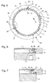
- the flange 12 is contoured so as to be able to gradually deform the ring 24 during its rotation (in the counterclockwise direction for these figures).
- This flange 12 comprises in particular a ramp 18 which bends the antagonistic surfaces of the ring 24.
- This ramp is here followed by a clearance 17 which allows the movement of notches projecting 27, 28, which internally comprises the ring 24, which a 27 is substantially parallel to a clearance 25 that includes the ring 24 on its outer face, at such a deformable zone 50, while the other 28 faces a substantially cylindrical bearing surface of the ring 24
- a hollow 26 separates these projecting notches 27 and 28 on the inner face of the ring 24.
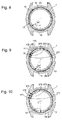
- the Figures 8 to 10 illustrate a second variant, quite similar to the previous one, also comprising a repetition at 120 °, the bottom 10 comprises here, after the ramp 18 and separated by intermediate reliefs, three clearances 171, 172, 173, which are arranged to cooperate successively with bosses 271, 272, 273 of the ring.
- the angular mark 19 of the bottom 10 makes it possible to locate the relative angular position of the middle part 1 and the bottom 10: 50 ° on the figure 8 , 30 ° on the figure 9 , 0 ° on the figure 10 .
- the invention is well suited to cases where the subassembly 100 comprises components 1 and 10 made of different materials, with different coefficients of expansion, or fragile or hard materials (ceramic, sapphire), which do not allow standard fastening methods.
- conventional configurations include assembling a gold case with a sapphire caseback, or a box entirely ceramic, a metal-ceramic combination, or the like.
- the third component 20 is preferably a ring, which may be made of different materials, in particular POM, polyurethane, polymer-based material, or elastomer, at least partially amorphous metal alloy, the chosen material determining the maximum tightening torque, thus a amorphous alloy ring allows a tightening torque of about 3.2 Nm, similar to the usual one of a bottom screwed on a middle, for a joint 9 of the same size.
- This ring can also be made of amorphous metal, stainless steel, CuBe, "Liquidmetal ⁇ ", or even bi-materials, for example with a plastic core with molded inserts, metal, or ceramic, or other.
- the advantage of such a ring, preferably in a polymeric elastic material or the like, is its ease of housing in a volume whose free space is very limited, where it is impossible to implement safely a metal element susceptible to break.
- the material of the third component 20 may also be more complex, especially in the form of an elastomer type material loaded with technical fibers such as "Kevlar®” or the like, or with an antiwear additive such as polytetrafluoroethylene said PTFE, or other.
- An important advantage of the invention is to require neither drilling nor tapping, but only simple machining achievable with a certain ease, thus avoiding any soiling or pollution of the watch, and allowing a moderate cost.
- the first component 1 is a middle and the second component 10 is a bottom.
- the presence of at least one seal is required.
- the first component 1 is a bottom and the second component 10 is a part of appearance, such as a medallion, or the like, attached to this bottom, in which case a seal between them is not necessary, and the presence of a spring that can perfectly suffice in a variant comprising repulsion means.
- the first component 1 is a middle part and the second component 10 is a flange or bezel, as visible on the figure 13 .
- This case is well suited to a variant in which a first component and a second component tend to be separated from each other, by magnetic repulsion or by an elastic element such as a rod, that is to say a thin ring, not necessarily closed, or more particularly a rod comprising segments similar to a ratchet to allow easy unidirectional maneuver, as in the particular case of use of the invention for a unidirectional bezel.
- a ring may be filiform, of substantially round section, or rectangular section, or other.
- the third component 20 is simply repulsion means itself, which substantially reduces the number of components while ensuring very good maintenance required.
- the first component 1 is a middle part or a tube attached to a middle part
- the second component 10 is a crown, as visible on the figure 14 .
- the second component 10 is a crown rod or a pusher. In these cases too, the presence of at least one seal is mandatory.
- the invention is suitable for many applications in watchmaking, for example for a helium valve on a diving watch, or for dressing components such as a bracelet, a buckle, a clasp, or other. It is the same in jewelry, for closing cufflinks, earrings, or for securing precious stones or decorated elements removably designed.
- the invention also relates to a timepiece or watch 1000 comprising such a dressing subassembly 100.
- the invention also relates to a jewel comprising such a subassembly 100.
- the invention makes it possible to have a subassembly with a bayonet connection, with a retaining ring mounted on a first component, in particular a substantially toroidal ring.
- This ring can also be opened, for example with a slot like a circlip or the like, to facilitate assembly.
- notches of the second component come to lock with notches of the ring.
- the invention makes it possible to ensure the perfect orientation of a locked component in its operating position.
- the invention also authorizes the cooperation of antagonistic components made of different materials, without expansion stress friction, elasticity, or other, without requiring external fastening element such as screw or the like, without screws nor machining may weaken particular materials such as ceramics, sapphire, and the like. It has a very good resistance to accidental or even voluntary unwinding by vibration or Chapuis-choc type.
- the invention also makes it possible to ensure the interchangeability of the components, and, consequently, an increased personalization of the watches or jewels of the users.
- This invention is applicable both to watches or jewelery made of precious materials that large series of achievements comprising low unit cost components, including plastic or similar.
- the invention is well suited to cases where the subassembly 100 comprises components 1 and 10 made of different materials, with different coefficients of expansion, or fragile or hard materials (ceramic, sapphire, precious stones, gems). , cameos), which do not allow standard attachment modes.
- conventional configurations include assembling a gold case with a sapphire caseback, or a box entirely ceramic, a metal-ceramic combination, or the like.
- the components 1 and 10 can thus be made of all kinds of materials: metal alloys, especially precious or titrated alloys, stainless steels, at least partially amorphous metal alloys, or "Liquidmetal ⁇ " or the like, ceramics, sapphire, minerals, hard stones, rubber, plastics and in particular thermoplastic elastomers known as TPE including TPU thermoplastic polyurethane, so-called PC polycarbonates, polyvinyl chlorides known as PVC, polyacetals or polyoxymethylene said POM, silicone, "nylon", to mention, without limitation, that materials used in watchmaking and jewelery.
Landscapes
- Physics & Mathematics (AREA)
- General Physics & Mathematics (AREA)
- Engineering & Computer Science (AREA)
- Manufacturing & Machinery (AREA)
- Adornments (AREA)
- Gasket Seals (AREA)
- Electric Clocks (AREA)
Priority Applications (6)
| Application Number | Priority Date | Filing Date | Title |
|---|---|---|---|
| CH00965/16A CH712740B1 (fr) | 2016-07-26 | 2016-07-26 | Sous-ensemble d'habillage pour pièce d'horlogerie, notamment une montre, ou pour bijou. |
| EP16181139.3A EP3276432B1 (de) | 2016-07-26 | 2016-07-26 | Untereinheit zur verkleidung einer uhr, armbanduhr oder eines schmuckstücks |
| US15/654,056 US10088806B2 (en) | 2016-07-26 | 2017-07-19 | Exterior sub-assembly for a timepiece or watch or piece of jewellery |
| JP2017141708A JP6453949B2 (ja) | 2016-07-26 | 2017-07-21 | 時計またはウォッチまたは宝飾品用の外装サブアセンブリ |
| CN201710610745.3A CN107656434B (zh) | 2016-07-26 | 2017-07-25 | 用于钟表或手表或珠宝饰品的外部子组件 |
| HK18109022.3A HK1249593A1 (zh) | 2016-07-26 | 2018-07-11 | 用於鐘錶或手錶或珠寶飾品的外部子組件 |
Applications Claiming Priority (1)
| Application Number | Priority Date | Filing Date | Title |
|---|---|---|---|
| EP16181139.3A EP3276432B1 (de) | 2016-07-26 | 2016-07-26 | Untereinheit zur verkleidung einer uhr, armbanduhr oder eines schmuckstücks |
Publications (2)
| Publication Number | Publication Date |
|---|---|
| EP3276432A1 true EP3276432A1 (de) | 2018-01-31 |
| EP3276432B1 EP3276432B1 (de) | 2020-03-25 |
Family
ID=56550756
Family Applications (1)
| Application Number | Title | Priority Date | Filing Date |
|---|---|---|---|
| EP16181139.3A Active EP3276432B1 (de) | 2016-07-26 | 2016-07-26 | Untereinheit zur verkleidung einer uhr, armbanduhr oder eines schmuckstücks |
Country Status (6)
| Country | Link |
|---|---|
| US (1) | US10088806B2 (de) |
| EP (1) | EP3276432B1 (de) |
| JP (1) | JP6453949B2 (de) |
| CN (1) | CN107656434B (de) |
| CH (1) | CH712740B1 (de) |
| HK (1) | HK1249593A1 (de) |
Cited By (5)
| Publication number | Priority date | Publication date | Assignee | Title |
|---|---|---|---|---|
| CN110308639A (zh) * | 2018-03-20 | 2019-10-08 | 奥米加股份有限公司 | 包括至少一个弹性臂的环形旋转表圈系统 |
| CN110308637A (zh) * | 2018-03-20 | 2019-10-08 | 奥米加股份有限公司 | 包括弹簧环的环形旋转表圈系统 |
| EP3936732A1 (de) | 2020-07-10 | 2022-01-12 | Rolex Sa | Uhrorgan mit gewinde |
| CH718418A1 (fr) * | 2021-03-10 | 2022-09-15 | Mft Dhorlogerie Audemars Piguet Sa | Elément de boîte pour pièce d'horlogerie comportant un poussoir en verre métallique massif. |
| EP4109181A1 (de) * | 2021-06-21 | 2022-12-28 | ETA SA Manufacture Horlogère Suisse | Zifferblatt, armbanduhr mit einem solchen zifferblatt und verfahren zum einbau eines solchen zifferblatts in eine armbanduhr |
Families Citing this family (13)
| Publication number | Priority date | Publication date | Assignee | Title |
|---|---|---|---|---|
| EP3674815B1 (de) * | 2018-12-27 | 2021-09-29 | Omega SA | Armbanduhrengehäuse, das mit einem kreisförmigen ring ausgestattet ist, und armbanduhr sowie montagekit für ein uhrenarmband, das dieses umfasst |
| EP3680729B1 (de) * | 2019-01-09 | 2024-04-24 | Blancpain SA | Ausrichtbarer boden für eine uhr |
| EP3699695B1 (de) | 2019-02-25 | 2022-07-06 | Comadur S.A. | Komponente mit mehreren verzierungen und/oder mehreren farben eines uhrwerks mit keramikstruktur |
| EP3712715A1 (de) | 2019-03-18 | 2020-09-23 | Montres Breguet S.A. | Armbanduhrengehäuse, das einen drehbaren aussenring umfasst |
| JP6924417B2 (ja) * | 2019-03-25 | 2021-08-25 | カシオ計算機株式会社 | ケース、ケースの製造方法および時計 |
| EP3796106B1 (de) * | 2019-09-20 | 2022-06-01 | The Swatch Group Research and Development Ltd | Untereinheit zur verkleidung einer uhr, armbanduhr oder eines schmuckstücks |
| EP3796104B1 (de) | 2019-09-20 | 2022-04-20 | The Swatch Group Research and Development Ltd | Untereinheit zur verkleidung einer uhr, armbanduhr oder eines schmuckstücks |
| EP3800514B1 (de) * | 2019-10-04 | 2024-01-17 | Comadur S.A. | Einrastfederring eines drehbaren aussenrings |
| EP3805869A1 (de) * | 2019-10-09 | 2021-04-14 | Meco S.A. | Geschraubte krone |
| EP3958068A1 (de) * | 2020-08-17 | 2022-02-23 | The Swatch Group Research and Development Ltd | Vorrichtung zur befestigung eines bodens auf einem gehäuserahmen einer uhr |
| EP3958067A1 (de) * | 2020-08-17 | 2022-02-23 | The Swatch Group Research and Development Ltd | Vorrichtung zur befestigung eines bodens auf einem gehäuserahmen einer uhr |
| EP4191347A1 (de) * | 2021-12-01 | 2023-06-07 | The Swatch Group Research and Development Ltd | Armbanduhrengehäuse mit einem boden, der in einer vordefinierten winkelposition ausgerichtet ist |
| EP4194968A1 (de) * | 2021-12-07 | 2023-06-14 | The Swatch Group Research and Development Ltd | Vorrichtung zur befestigung und ausrichtung eines bodens auf einem gehäuserahmen einer uhr |
Citations (4)
| Publication number | Priority date | Publication date | Assignee | Title |
|---|---|---|---|---|
| EP1431845A1 (de) * | 2002-12-20 | 2004-06-23 | Rolex S.A. | Uhrgehäuse |
| EP1835363A1 (de) * | 2006-03-16 | 2007-09-19 | Officine Panerai Branch of Richemont International SA | Uhr mit einer umdrehbaren Lunette |
| EP2672333A1 (de) * | 2012-06-06 | 2013-12-11 | Omega SA | System eines drehbaren Außenrings (einer Uhr) |
| EP2672331A1 (de) * | 2012-06-06 | 2013-12-11 | Omega SA | Uhrgehäuse mit Ausstattung mit verbesserter Fixierung |
Family Cites Families (13)
| Publication number | Priority date | Publication date | Assignee | Title |
|---|---|---|---|---|
| CH678862A4 (de) * | 1962-06-05 | 1964-11-14 | ||
| JPS534134Y2 (de) * | 1973-08-30 | 1978-02-01 | ||
| CH617816GA3 (de) * | 1978-05-23 | 1980-06-30 | ||
| JPS57112983U (de) * | 1980-12-30 | 1982-07-13 | ||
| CH690140A5 (fr) * | 1996-03-05 | 2000-05-15 | Smh Management Services Ag | Boîte de montre munie d'une lunette tournante. |
| JP3712911B2 (ja) * | 2000-03-30 | 2005-11-02 | セイコーインスツル株式会社 | 回転ベゼル付き腕時計ケース |
| WO2001075530A1 (fr) * | 2000-03-30 | 2001-10-11 | Seiko Instruments Inc. | Boitier de montre-bracelet muni d'un cadran rotatif |
| EP1278108B1 (de) * | 2001-07-18 | 2008-03-12 | The Swatch Group Management Services AG | Vorrichtung zur Verstellung der Ausrichtung eines Bodens, der auf das Mittelteil eines Uhrgehäuses geschraubt ist, in bezug auf eine Achse 12H-6H |
| JP2009503487A (ja) * | 2005-07-29 | 2009-01-29 | リシュモン アンテルナシオナル ソシエテ アノニム | 磁界を遮蔽するためのケース |
| WO2014203973A1 (ja) * | 2013-06-20 | 2014-12-24 | シチズンホールディングス株式会社 | 時計 |
| US9568808B2 (en) * | 2014-08-07 | 2017-02-14 | Houdinix Llc | Low-profile lens mount |
| EP3002639B1 (de) * | 2014-10-01 | 2018-01-31 | Montres Breguet SA | Spieluhrlunette mit verbesserter akustischer Leistung |
| CH710995A2 (fr) * | 2015-04-27 | 2016-10-31 | Eta Sa Mft Horlogere Suisse | Montre destinée à être montée sur un support amovible. |
-
2016
- 2016-07-26 EP EP16181139.3A patent/EP3276432B1/de active Active
- 2016-07-26 CH CH00965/16A patent/CH712740B1/fr unknown
-
2017
- 2017-07-19 US US15/654,056 patent/US10088806B2/en active Active
- 2017-07-21 JP JP2017141708A patent/JP6453949B2/ja active Active
- 2017-07-25 CN CN201710610745.3A patent/CN107656434B/zh active Active
-
2018
- 2018-07-11 HK HK18109022.3A patent/HK1249593A1/zh unknown
Patent Citations (4)
| Publication number | Priority date | Publication date | Assignee | Title |
|---|---|---|---|---|
| EP1431845A1 (de) * | 2002-12-20 | 2004-06-23 | Rolex S.A. | Uhrgehäuse |
| EP1835363A1 (de) * | 2006-03-16 | 2007-09-19 | Officine Panerai Branch of Richemont International SA | Uhr mit einer umdrehbaren Lunette |
| EP2672333A1 (de) * | 2012-06-06 | 2013-12-11 | Omega SA | System eines drehbaren Außenrings (einer Uhr) |
| EP2672331A1 (de) * | 2012-06-06 | 2013-12-11 | Omega SA | Uhrgehäuse mit Ausstattung mit verbesserter Fixierung |
Cited By (10)
| Publication number | Priority date | Publication date | Assignee | Title |
|---|---|---|---|---|
| CN110308639A (zh) * | 2018-03-20 | 2019-10-08 | 奥米加股份有限公司 | 包括至少一个弹性臂的环形旋转表圈系统 |
| CN110308637A (zh) * | 2018-03-20 | 2019-10-08 | 奥米加股份有限公司 | 包括弹簧环的环形旋转表圈系统 |
| CN110308639B (zh) * | 2018-03-20 | 2021-08-13 | 奥米加股份有限公司 | 包括至少一个弹性臂的环形旋转表圈系统 |
| CN110308637B (zh) * | 2018-03-20 | 2022-04-08 | 奥米加股份有限公司 | 包括弹簧环的环形旋转表圈系统 |
| US11385597B2 (en) | 2018-03-20 | 2022-07-12 | Omega Sa | Annular rotating bezel system comprising a spring ring |
| EP3936732A1 (de) | 2020-07-10 | 2022-01-12 | Rolex Sa | Uhrorgan mit gewinde |
| US11880169B2 (en) | 2020-07-10 | 2024-01-23 | Rolex Sa | Threaded timepiece member |
| CH718418A1 (fr) * | 2021-03-10 | 2022-09-15 | Mft Dhorlogerie Audemars Piguet Sa | Elément de boîte pour pièce d'horlogerie comportant un poussoir en verre métallique massif. |
| EP4071557A1 (de) * | 2021-03-10 | 2022-10-12 | Manufacture d'Horlogerie Audemars Piguet SA | Gehäuseelement für uhr, das einen drücker aus massivem metallischem glas umfasst |
| EP4109181A1 (de) * | 2021-06-21 | 2022-12-28 | ETA SA Manufacture Horlogère Suisse | Zifferblatt, armbanduhr mit einem solchen zifferblatt und verfahren zum einbau eines solchen zifferblatts in eine armbanduhr |
Also Published As
| Publication number | Publication date |
|---|---|
| CN107656434A (zh) | 2018-02-02 |
| EP3276432B1 (de) | 2020-03-25 |
| JP6453949B2 (ja) | 2019-01-16 |
| US10088806B2 (en) | 2018-10-02 |
| CH712740A2 (fr) | 2018-01-31 |
| JP2018017731A (ja) | 2018-02-01 |
| CN107656434B (zh) | 2020-12-01 |
| HK1249593A1 (zh) | 2018-11-02 |
| CH712740B1 (fr) | 2020-08-31 |
| US20180032034A1 (en) | 2018-02-01 |
Similar Documents
| Publication | Publication Date | Title |
|---|---|---|
| EP3276432B1 (de) | Untereinheit zur verkleidung einer uhr, armbanduhr oder eines schmuckstücks | |
| EP3276187B1 (de) | Untereinheit zum zusammensetzen einer uhr, armbanduhr oder eines schmuckstücks | |
| EP2718770A1 (de) | Vorrichtung zum ausrichten eines schraubenelements einer uhr | |
| EP3279745B1 (de) | Ausrichtbare geschraubte krone | |
| EP2182417A2 (de) | Kronrad zum Aufschrauben und Orientierungsverfahren eines solchen Kronrads auf einem Armbanduhrengehäuse | |
| EP3574377A1 (de) | Uhrengehäuse mit in einem mittelstück durch eine hintere blende gehaltener kapsel | |
| CH705043A2 (fr) | Pièce d'horlogerie portable incluant un bouton-poussoir. | |
| EP3821300A1 (de) | Uhr mit einer drehbaren blende mit einem mit einem integrierten heliumventil versehenen blendenverriegelungssystem | |
| CH714764A2 (fr) | Pièce d'horlogerie munie d'une couronne. | |
| EP3276433B1 (de) | Untereinheit des gehäuses einer uhr, armbanduhr oder eines schmuckstücks | |
| EP3796104B1 (de) | Untereinheit zur verkleidung einer uhr, armbanduhr oder eines schmuckstücks | |
| EP3796106B1 (de) | Untereinheit zur verkleidung einer uhr, armbanduhr oder eines schmuckstücks | |
| CH712741A2 (fr) | Sous-ensemble d'habillage pour pièce d'horlogerie, notamment une montre, ou pour bijou. | |
| EP2915445B1 (de) | Vorrichtung und Verfahren zum drehbaren Zusammenbau von mindestens zwei Teilen, und Einheit aus den zwei zusammengebauten Teilen | |
| EP2182416A1 (de) | Einrichtung zur Positionierung und Halterung eines Bodens und Verfahren zur Positionierung und Halterung dieses Bodens auf einem Mittelteil | |
| EP3321749B1 (de) | Dichtungsfuge für uhrwerk | |
| EP4194967A1 (de) | Vorrichtung zur befestigung eines bodens auf einem gehäuserahmen einer uhr | |
| EP3958067A1 (de) | Vorrichtung zur befestigung eines bodens auf einem gehäuserahmen einer uhr | |
| CH717758A2 (fr) | Dispositif de fixation d'un fond sur une carrure pour pièce d'horlogerie. | |
| CH719212A2 (fr) | Dispositif de fixation d'un fond sur une carrure pour pièce d'horlogerie. | |
| EP4174583A1 (de) | Steuervorrichtung für eine uhr | |
| CH718095A2 (fr) | Montre comprenant un boîtier étanche logé dans une carrure extérieure. | |
| EP4009118A1 (de) | Vorrichtung zum zusammenbau von zwei uhrencomponenten | |
| EP4155834A1 (de) | Gesichertes steuerorgan für uhr | |
| EP4150410A1 (de) | Armbanduhrengehäuse, das ein drehbares element umfasst |
Legal Events
| Date | Code | Title | Description |
|---|---|---|---|
| PUAI | Public reference made under article 153(3) epc to a published international application that has entered the european phase |
Free format text: ORIGINAL CODE: 0009012 |
|
| STAA | Information on the status of an ep patent application or granted ep patent |
Free format text: STATUS: THE APPLICATION HAS BEEN PUBLISHED |
|
| AK | Designated contracting states |
Kind code of ref document: A1 Designated state(s): AL AT BE BG CH CY CZ DE DK EE ES FI FR GB GR HR HU IE IS IT LI LT LU LV MC MK MT NL NO PL PT RO RS SE SI SK SM TR |
|
| AX | Request for extension of the european patent |
Extension state: BA ME |
|
| STAA | Information on the status of an ep patent application or granted ep patent |
Free format text: STATUS: REQUEST FOR EXAMINATION WAS MADE |
|
| 17P | Request for examination filed |
Effective date: 20180731 |
|
| RBV | Designated contracting states (corrected) |
Designated state(s): AL AT BE BG CH CY CZ DE DK EE ES FI FR GB GR HR HU IE IS IT LI LT LU LV MC MK MT NL NO PL PT RO RS SE SI SK SM TR |
|
| REG | Reference to a national code |
Ref country code: DE Ref legal event code: R079 Ref document number: 602016032416 Country of ref document: DE Free format text: PREVIOUS MAIN CLASS: G04B0019280000 Ipc: G04B0037000000 |
|
| GRAJ | Information related to disapproval of communication of intention to grant by the applicant or resumption of examination proceedings by the epo deleted |
Free format text: ORIGINAL CODE: EPIDOSDIGR1 |
|
| STAA | Information on the status of an ep patent application or granted ep patent |
Free format text: STATUS: GRANT OF PATENT IS INTENDED |
|
| GRAP | Despatch of communication of intention to grant a patent |
Free format text: ORIGINAL CODE: EPIDOSNIGR1 |
|
| RIC1 | Information provided on ipc code assigned before grant |
Ipc: G04B 37/00 20060101AFI20191022BHEP Ipc: G04B 19/28 20060101ALI20191022BHEP Ipc: G04B 37/11 20060101ALI20191022BHEP Ipc: G04B 37/08 20060101ALI20191022BHEP |
|
| INTG | Intention to grant announced |
Effective date: 20191112 |
|
| RIN1 | Information on inventor provided before grant (corrected) |
Inventor name: KNUCHEL, DANIEL Inventor name: VUILLE, PIERRY Inventor name: CATANESE, ROCCO |
|
| GRAS | Grant fee paid |
Free format text: ORIGINAL CODE: EPIDOSNIGR3 |
|
| GRAA | (expected) grant |
Free format text: ORIGINAL CODE: 0009210 |
|
| STAA | Information on the status of an ep patent application or granted ep patent |
Free format text: STATUS: THE PATENT HAS BEEN GRANTED |
|
| AK | Designated contracting states |
Kind code of ref document: B1 Designated state(s): AL AT BE BG CH CY CZ DE DK EE ES FI FR GB GR HR HU IE IS IT LI LT LU LV MC MK MT NL NO PL PT RO RS SE SI SK SM TR |
|
| REG | Reference to a national code |
Ref country code: GB Ref legal event code: FG4D Free format text: NOT ENGLISH |
|
| REG | Reference to a national code |
Ref country code: CH Ref legal event code: NV Representative=s name: ICB INGENIEURS CONSEILS EN BREVETS SA, CH Ref country code: AT Ref legal event code: REF Ref document number: 1249256 Country of ref document: AT Kind code of ref document: T Effective date: 20200415 Ref country code: IE Ref legal event code: FG4D Free format text: LANGUAGE OF EP DOCUMENT: FRENCH |
|
| REG | Reference to a national code |
Ref country code: DE Ref legal event code: R096 Ref document number: 602016032416 Country of ref document: DE |
|
| PG25 | Lapsed in a contracting state [announced via postgrant information from national office to epo] |
Ref country code: RS Free format text: LAPSE BECAUSE OF FAILURE TO SUBMIT A TRANSLATION OF THE DESCRIPTION OR TO PAY THE FEE WITHIN THE PRESCRIBED TIME-LIMIT Effective date: 20200325 Ref country code: FI Free format text: LAPSE BECAUSE OF FAILURE TO SUBMIT A TRANSLATION OF THE DESCRIPTION OR TO PAY THE FEE WITHIN THE PRESCRIBED TIME-LIMIT Effective date: 20200325 Ref country code: NO Free format text: LAPSE BECAUSE OF FAILURE TO SUBMIT A TRANSLATION OF THE DESCRIPTION OR TO PAY THE FEE WITHIN THE PRESCRIBED TIME-LIMIT Effective date: 20200625 |
|
| PG25 | Lapsed in a contracting state [announced via postgrant information from national office to epo] |
Ref country code: BG Free format text: LAPSE BECAUSE OF FAILURE TO SUBMIT A TRANSLATION OF THE DESCRIPTION OR TO PAY THE FEE WITHIN THE PRESCRIBED TIME-LIMIT Effective date: 20200625 Ref country code: HR Free format text: LAPSE BECAUSE OF FAILURE TO SUBMIT A TRANSLATION OF THE DESCRIPTION OR TO PAY THE FEE WITHIN THE PRESCRIBED TIME-LIMIT Effective date: 20200325 Ref country code: SE Free format text: LAPSE BECAUSE OF FAILURE TO SUBMIT A TRANSLATION OF THE DESCRIPTION OR TO PAY THE FEE WITHIN THE PRESCRIBED TIME-LIMIT Effective date: 20200325 Ref country code: LV Free format text: LAPSE BECAUSE OF FAILURE TO SUBMIT A TRANSLATION OF THE DESCRIPTION OR TO PAY THE FEE WITHIN THE PRESCRIBED TIME-LIMIT Effective date: 20200325 Ref country code: GR Free format text: LAPSE BECAUSE OF FAILURE TO SUBMIT A TRANSLATION OF THE DESCRIPTION OR TO PAY THE FEE WITHIN THE PRESCRIBED TIME-LIMIT Effective date: 20200626 |
|
| REG | Reference to a national code |
Ref country code: NL Ref legal event code: MP Effective date: 20200325 |
|
| REG | Reference to a national code |
Ref country code: LT Ref legal event code: MG4D |
|
| PG25 | Lapsed in a contracting state [announced via postgrant information from national office to epo] |
Ref country code: NL Free format text: LAPSE BECAUSE OF FAILURE TO SUBMIT A TRANSLATION OF THE DESCRIPTION OR TO PAY THE FEE WITHIN THE PRESCRIBED TIME-LIMIT Effective date: 20200325 |
|
| PG25 | Lapsed in a contracting state [announced via postgrant information from national office to epo] |
Ref country code: LT Free format text: LAPSE BECAUSE OF FAILURE TO SUBMIT A TRANSLATION OF THE DESCRIPTION OR TO PAY THE FEE WITHIN THE PRESCRIBED TIME-LIMIT Effective date: 20200325 Ref country code: SM Free format text: LAPSE BECAUSE OF FAILURE TO SUBMIT A TRANSLATION OF THE DESCRIPTION OR TO PAY THE FEE WITHIN THE PRESCRIBED TIME-LIMIT Effective date: 20200325 Ref country code: PT Free format text: LAPSE BECAUSE OF FAILURE TO SUBMIT A TRANSLATION OF THE DESCRIPTION OR TO PAY THE FEE WITHIN THE PRESCRIBED TIME-LIMIT Effective date: 20200818 Ref country code: EE Free format text: LAPSE BECAUSE OF FAILURE TO SUBMIT A TRANSLATION OF THE DESCRIPTION OR TO PAY THE FEE WITHIN THE PRESCRIBED TIME-LIMIT Effective date: 20200325 Ref country code: SK Free format text: LAPSE BECAUSE OF FAILURE TO SUBMIT A TRANSLATION OF THE DESCRIPTION OR TO PAY THE FEE WITHIN THE PRESCRIBED TIME-LIMIT Effective date: 20200325 Ref country code: IS Free format text: LAPSE BECAUSE OF FAILURE TO SUBMIT A TRANSLATION OF THE DESCRIPTION OR TO PAY THE FEE WITHIN THE PRESCRIBED TIME-LIMIT Effective date: 20200725 Ref country code: RO Free format text: LAPSE BECAUSE OF FAILURE TO SUBMIT A TRANSLATION OF THE DESCRIPTION OR TO PAY THE FEE WITHIN THE PRESCRIBED TIME-LIMIT Effective date: 20200325 Ref country code: CZ Free format text: LAPSE BECAUSE OF FAILURE TO SUBMIT A TRANSLATION OF THE DESCRIPTION OR TO PAY THE FEE WITHIN THE PRESCRIBED TIME-LIMIT Effective date: 20200325 |
|
| REG | Reference to a national code |
Ref country code: AT Ref legal event code: MK05 Ref document number: 1249256 Country of ref document: AT Kind code of ref document: T Effective date: 20200325 |
|
| REG | Reference to a national code |
Ref country code: DE Ref legal event code: R097 Ref document number: 602016032416 Country of ref document: DE |
|
| PG25 | Lapsed in a contracting state [announced via postgrant information from national office to epo] |
Ref country code: IT Free format text: LAPSE BECAUSE OF FAILURE TO SUBMIT A TRANSLATION OF THE DESCRIPTION OR TO PAY THE FEE WITHIN THE PRESCRIBED TIME-LIMIT Effective date: 20200325 Ref country code: DK Free format text: LAPSE BECAUSE OF FAILURE TO SUBMIT A TRANSLATION OF THE DESCRIPTION OR TO PAY THE FEE WITHIN THE PRESCRIBED TIME-LIMIT Effective date: 20200325 Ref country code: AT Free format text: LAPSE BECAUSE OF FAILURE TO SUBMIT A TRANSLATION OF THE DESCRIPTION OR TO PAY THE FEE WITHIN THE PRESCRIBED TIME-LIMIT Effective date: 20200325 Ref country code: ES Free format text: LAPSE BECAUSE OF FAILURE TO SUBMIT A TRANSLATION OF THE DESCRIPTION OR TO PAY THE FEE WITHIN THE PRESCRIBED TIME-LIMIT Effective date: 20200325 |
|
| PLBE | No opposition filed within time limit |
Free format text: ORIGINAL CODE: 0009261 |
|
| STAA | Information on the status of an ep patent application or granted ep patent |
Free format text: STATUS: NO OPPOSITION FILED WITHIN TIME LIMIT |
|
| PG25 | Lapsed in a contracting state [announced via postgrant information from national office to epo] |
Ref country code: PL Free format text: LAPSE BECAUSE OF FAILURE TO SUBMIT A TRANSLATION OF THE DESCRIPTION OR TO PAY THE FEE WITHIN THE PRESCRIBED TIME-LIMIT Effective date: 20200325 Ref country code: MC Free format text: LAPSE BECAUSE OF FAILURE TO SUBMIT A TRANSLATION OF THE DESCRIPTION OR TO PAY THE FEE WITHIN THE PRESCRIBED TIME-LIMIT Effective date: 20200325 |
|
| 26N | No opposition filed |
Effective date: 20210112 |
|
| REG | Reference to a national code |
Ref country code: BE Ref legal event code: MM Effective date: 20200731 |
|
| PG25 | Lapsed in a contracting state [announced via postgrant information from national office to epo] |
Ref country code: LU Free format text: LAPSE BECAUSE OF NON-PAYMENT OF DUE FEES Effective date: 20200726 |
|
| PG25 | Lapsed in a contracting state [announced via postgrant information from national office to epo] |
Ref country code: BE Free format text: LAPSE BECAUSE OF NON-PAYMENT OF DUE FEES Effective date: 20200731 Ref country code: SI Free format text: LAPSE BECAUSE OF FAILURE TO SUBMIT A TRANSLATION OF THE DESCRIPTION OR TO PAY THE FEE WITHIN THE PRESCRIBED TIME-LIMIT Effective date: 20200325 |
|
| PG25 | Lapsed in a contracting state [announced via postgrant information from national office to epo] |
Ref country code: IE Free format text: LAPSE BECAUSE OF NON-PAYMENT OF DUE FEES Effective date: 20200726 |
|
| PG25 | Lapsed in a contracting state [announced via postgrant information from national office to epo] |
Ref country code: TR Free format text: LAPSE BECAUSE OF FAILURE TO SUBMIT A TRANSLATION OF THE DESCRIPTION OR TO PAY THE FEE WITHIN THE PRESCRIBED TIME-LIMIT Effective date: 20200325 Ref country code: MT Free format text: LAPSE BECAUSE OF FAILURE TO SUBMIT A TRANSLATION OF THE DESCRIPTION OR TO PAY THE FEE WITHIN THE PRESCRIBED TIME-LIMIT Effective date: 20200325 Ref country code: CY Free format text: LAPSE BECAUSE OF FAILURE TO SUBMIT A TRANSLATION OF THE DESCRIPTION OR TO PAY THE FEE WITHIN THE PRESCRIBED TIME-LIMIT Effective date: 20200325 |
|
| PG25 | Lapsed in a contracting state [announced via postgrant information from national office to epo] |
Ref country code: MK Free format text: LAPSE BECAUSE OF FAILURE TO SUBMIT A TRANSLATION OF THE DESCRIPTION OR TO PAY THE FEE WITHIN THE PRESCRIBED TIME-LIMIT Effective date: 20200325 Ref country code: AL Free format text: LAPSE BECAUSE OF FAILURE TO SUBMIT A TRANSLATION OF THE DESCRIPTION OR TO PAY THE FEE WITHIN THE PRESCRIBED TIME-LIMIT Effective date: 20200325 |
|
| PGFP | Annual fee paid to national office [announced via postgrant information from national office to epo] |
Ref country code: FR Payment date: 20230621 Year of fee payment: 8 |
|
| P01 | Opt-out of the competence of the unified patent court (upc) registered |
Effective date: 20230701 |
|
| PGFP | Annual fee paid to national office [announced via postgrant information from national office to epo] |
Ref country code: GB Payment date: 20230620 Year of fee payment: 8 Ref country code: CH Payment date: 20230801 Year of fee payment: 8 |
|
| PGFP | Annual fee paid to national office [announced via postgrant information from national office to epo] |
Ref country code: DE Payment date: 20230620 Year of fee payment: 8 |