EP3276432A1 - Casing subassembly for a timepiece, watch or jewel - Google Patents
Casing subassembly for a timepiece, watch or jewel Download PDFInfo
- Publication number
- EP3276432A1 EP3276432A1 EP16181139.3A EP16181139A EP3276432A1 EP 3276432 A1 EP3276432 A1 EP 3276432A1 EP 16181139 A EP16181139 A EP 16181139A EP 3276432 A1 EP3276432 A1 EP 3276432A1
- Authority
- EP
- European Patent Office
- Prior art keywords
- component
- ring
- subassembly
- relative
- rotation
- Prior art date
- Legal status (The legal status is an assumption and is not a legal conclusion. Google has not performed a legal analysis and makes no representation as to the accuracy of the status listed.)
- Granted
Links
- 239000010437 gem Substances 0.000 title claims abstract description 15
- 229910001751 gemstone Inorganic materials 0.000 title claims abstract description 11
- 238000005253 cladding Methods 0.000 claims description 19
- 230000000295 complement effect Effects 0.000 claims description 18
- 238000003780 insertion Methods 0.000 claims description 11
- 230000037431 insertion Effects 0.000 claims description 11
- 230000000284 resting effect Effects 0.000 claims 1
- 239000000463 material Substances 0.000 description 16
- 239000000919 ceramic Substances 0.000 description 9
- 238000007789 sealing Methods 0.000 description 8
- 230000006835 compression Effects 0.000 description 6
- 238000007906 compression Methods 0.000 description 6
- 229910052594 sapphire Inorganic materials 0.000 description 6
- 239000010980 sapphire Substances 0.000 description 6
- 229920006324 polyoxymethylene Polymers 0.000 description 5
- 230000008901 benefit Effects 0.000 description 4
- 230000000694 effects Effects 0.000 description 4
- 230000006870 function Effects 0.000 description 4
- 229910000808 amorphous metal alloy Inorganic materials 0.000 description 3
- 229920001971 elastomer Polymers 0.000 description 3
- 238000003754 machining Methods 0.000 description 3
- 238000012423 maintenance Methods 0.000 description 3
- 230000007246 mechanism Effects 0.000 description 3
- 239000004033 plastic Substances 0.000 description 3
- 229920003023 plastic Polymers 0.000 description 3
- 239000004433 Thermoplastic polyurethane Substances 0.000 description 2
- 230000003042 antagnostic effect Effects 0.000 description 2
- 238000010586 diagram Methods 0.000 description 2
- 239000013013 elastic material Substances 0.000 description 2
- 239000000806 elastomer Substances 0.000 description 2
- PCHJSUWPFVWCPO-UHFFFAOYSA-N gold Chemical compound [Au] PCHJSUWPFVWCPO-UHFFFAOYSA-N 0.000 description 2
- 239000010931 gold Substances 0.000 description 2
- 229910052737 gold Inorganic materials 0.000 description 2
- 238000005304 joining Methods 0.000 description 2
- 229910001338 liquidmetal Inorganic materials 0.000 description 2
- 238000004519 manufacturing process Methods 0.000 description 2
- 239000002184 metal Substances 0.000 description 2
- 229910052751 metal Inorganic materials 0.000 description 2
- 239000004417 polycarbonate Substances 0.000 description 2
- -1 polytetrafluoroethylene Polymers 0.000 description 2
- 229920001343 polytetrafluoroethylene Polymers 0.000 description 2
- 239000004810 polytetrafluoroethylene Substances 0.000 description 2
- 229920002635 polyurethane Polymers 0.000 description 2
- 239000004814 polyurethane Substances 0.000 description 2
- 229920000915 polyvinyl chloride Polymers 0.000 description 2
- 230000002441 reversible effect Effects 0.000 description 2
- 230000035807 sensation Effects 0.000 description 2
- 229910001220 stainless steel Inorganic materials 0.000 description 2
- 229920002725 thermoplastic elastomer Polymers 0.000 description 2
- 229920002803 thermoplastic polyurethane Polymers 0.000 description 2
- 230000002747 voluntary effect Effects 0.000 description 2
- 206010009696 Clumsiness Diseases 0.000 description 1
- 229920000271 Kevlar® Polymers 0.000 description 1
- 239000004677 Nylon Substances 0.000 description 1
- 229930040373 Paraformaldehyde Natural products 0.000 description 1
- 241000287107 Passer Species 0.000 description 1
- 230000009471 action Effects 0.000 description 1
- 229910045601 alloy Inorganic materials 0.000 description 1
- 239000000956 alloy Substances 0.000 description 1
- 239000007866 anti-wear additive Substances 0.000 description 1
- 230000003416 augmentation Effects 0.000 description 1
- 230000000903 blocking effect Effects 0.000 description 1
- 238000004140 cleaning Methods 0.000 description 1
- 230000001186 cumulative effect Effects 0.000 description 1
- 238000005034 decoration Methods 0.000 description 1
- 230000003247 decreasing effect Effects 0.000 description 1
- 238000013461 design Methods 0.000 description 1
- 230000009189 diving Effects 0.000 description 1
- 238000005553 drilling Methods 0.000 description 1
- 230000005489 elastic deformation Effects 0.000 description 1
- 235000021183 entrée Nutrition 0.000 description 1
- 239000000835 fiber Substances 0.000 description 1
- 229910052734 helium Inorganic materials 0.000 description 1
- 239000001307 helium Substances 0.000 description 1
- SWQJXJOGLNCZEY-UHFFFAOYSA-N helium atom Chemical compound [He] SWQJXJOGLNCZEY-UHFFFAOYSA-N 0.000 description 1
- 229910052500 inorganic mineral Inorganic materials 0.000 description 1
- 238000005461 lubrication Methods 0.000 description 1
- 229910001092 metal group alloy Inorganic materials 0.000 description 1
- 239000007769 metal material Substances 0.000 description 1
- 239000005300 metallic glass Substances 0.000 description 1
- 238000000034 method Methods 0.000 description 1
- 239000011707 mineral Substances 0.000 description 1
- 229920001778 nylon Polymers 0.000 description 1
- 230000002093 peripheral effect Effects 0.000 description 1
- 229920000515 polycarbonate Polymers 0.000 description 1
- 229920000642 polymer Polymers 0.000 description 1
- 229920001296 polysiloxane Polymers 0.000 description 1
- 230000000750 progressive effect Effects 0.000 description 1
- 238000012797 qualification Methods 0.000 description 1
- 230000008439 repair process Effects 0.000 description 1
- 238000010079 rubber tapping Methods 0.000 description 1
- 239000010935 stainless steel Substances 0.000 description 1
- 230000000007 visual effect Effects 0.000 description 1
Images

Classifications
-
- G—PHYSICS
- G04—HOROLOGY
- G04B—MECHANICALLY-DRIVEN CLOCKS OR WATCHES; MECHANICAL PARTS OF CLOCKS OR WATCHES IN GENERAL; TIME PIECES USING THE POSITION OF THE SUN, MOON OR STARS
- G04B37/00—Cases
- G04B37/0008—Cases for pocket watches and wrist watches
-
- G—PHYSICS
- G04—HOROLOGY
- G04B—MECHANICALLY-DRIVEN CLOCKS OR WATCHES; MECHANICAL PARTS OF CLOCKS OR WATCHES IN GENERAL; TIME PIECES USING THE POSITION OF THE SUN, MOON OR STARS
- G04B45/00—Time pieces of which the indicating means or cases provoke special effects, e.g. aesthetic effects
-
- A—HUMAN NECESSITIES
- A44—HABERDASHERY; JEWELLERY
- A44C—PERSONAL ADORNMENTS, e.g. JEWELLERY; COINS
- A44C25/00—Miscellaneous fancy ware for personal wear, e.g. pendants, crosses, crucifixes, charms
-
- A—HUMAN NECESSITIES
- A44—HABERDASHERY; JEWELLERY
- A44C—PERSONAL ADORNMENTS, e.g. JEWELLERY; COINS
- A44C27/00—Making jewellery or other personal adornments
-
- G—PHYSICS
- G04—HOROLOGY
- G04B—MECHANICALLY-DRIVEN CLOCKS OR WATCHES; MECHANICAL PARTS OF CLOCKS OR WATCHES IN GENERAL; TIME PIECES USING THE POSITION OF THE SUN, MOON OR STARS
- G04B19/00—Indicating the time by visual means
- G04B19/28—Adjustable guide marks or pointers for indicating determined points of time
- G04B19/283—Adjustable guide marks or pointers for indicating determined points of time on rotatable rings, i.e. bezel
- G04B19/286—Adjustable guide marks or pointers for indicating determined points of time on rotatable rings, i.e. bezel with locking means to prevent undesired rotations in both directions
-
- G—PHYSICS
- G04—HOROLOGY
- G04B—MECHANICALLY-DRIVEN CLOCKS OR WATCHES; MECHANICAL PARTS OF CLOCKS OR WATCHES IN GENERAL; TIME PIECES USING THE POSITION OF THE SUN, MOON OR STARS
- G04B37/00—Cases
-
- G—PHYSICS
- G04—HOROLOGY
- G04B—MECHANICALLY-DRIVEN CLOCKS OR WATCHES; MECHANICAL PARTS OF CLOCKS OR WATCHES IN GENERAL; TIME PIECES USING THE POSITION OF THE SUN, MOON OR STARS
- G04B37/00—Cases
- G04B37/08—Hermetic sealing of openings, joints, passages or slits
-
- G—PHYSICS
- G04—HOROLOGY
- G04B—MECHANICALLY-DRIVEN CLOCKS OR WATCHES; MECHANICAL PARTS OF CLOCKS OR WATCHES IN GENERAL; TIME PIECES USING THE POSITION OF THE SUN, MOON OR STARS
- G04B37/00—Cases
- G04B37/08—Hermetic sealing of openings, joints, passages or slits
- G04B37/084—Complete encasings for wrist or pocket watches without means for hermetic sealing of winding stem or crown
-
- G—PHYSICS
- G04—HOROLOGY
- G04B—MECHANICALLY-DRIVEN CLOCKS OR WATCHES; MECHANICAL PARTS OF CLOCKS OR WATCHES IN GENERAL; TIME PIECES USING THE POSITION OF THE SUN, MOON OR STARS
- G04B37/00—Cases
- G04B37/08—Hermetic sealing of openings, joints, passages or slits
- G04B37/11—Hermetic sealing of openings, joints, passages or slits of the back cover of pocket or wrist watches
-
- G—PHYSICS
- G04—HOROLOGY
- G04B—MECHANICALLY-DRIVEN CLOCKS OR WATCHES; MECHANICAL PARTS OF CLOCKS OR WATCHES IN GENERAL; TIME PIECES USING THE POSITION OF THE SUN, MOON OR STARS
- G04B47/00—Time-pieces combined with other articles which do not interfere with the running or the time-keeping of the time-piece
- G04B47/04—Time-pieces combined with other articles which do not interfere with the running or the time-keeping of the time-piece with attached ornaments or amusement apparatus
-
- G—PHYSICS
- G04—HOROLOGY
- G04B—MECHANICALLY-DRIVEN CLOCKS OR WATCHES; MECHANICAL PARTS OF CLOCKS OR WATCHES IN GENERAL; TIME PIECES USING THE POSITION OF THE SUN, MOON OR STARS
- G04B19/00—Indicating the time by visual means
-
- G—PHYSICS
- G04—HOROLOGY
- G04B—MECHANICALLY-DRIVEN CLOCKS OR WATCHES; MECHANICAL PARTS OF CLOCKS OR WATCHES IN GENERAL; TIME PIECES USING THE POSITION OF THE SUN, MOON OR STARS
- G04B47/00—Time-pieces combined with other articles which do not interfere with the running or the time-keeping of the time-piece
Abstract
Sous-ensemble d'habillage (100) pour pièce d'horlogerie ou montre ou bijou, comportant un premier composant (1) et un deuxième composant (10), agencé pour un ajustement à baïonnette entre deux rebords (2) et deux ailes (12) que comportent ce premier composant (1) et ce deuxième composant (10), et apte à occuper une position assemblée et indexée des premier (1) et deuxième (10) composants, ledit sous-ensemble (100) comportant un troisième composant (20) en forme de bague intercalé entre les premier (1) et deuxième (10) composants, fixe en rotation par rapport à l'un d'eux et comportant une zone (50) déformable élastiquement, opposant un couple résistant variable à tout couple tangentiel relatif entre les premier (1) et deuxième (10) composants, et comportant un cran (26) coopérant avec un relief (18) du composant (1, 10) non lié au troisième composant (20), un cran particulier (26) indexant angulairement ces premier (1) et deuxième (10) composants.Subset assembly (100) for a timepiece or watch or jewel, comprising a first component (1) and a second component (10), arranged for a bayonet fit between two flanges (2) and two wings ( 12) that comprise this first component (1) and the second component (10), and adapted to occupy an assembled and indexed position of the first (1) and second (10) components, said subassembly (100) comprising a third component (20) in the form of a ring interposed between the first (1) and second (10) components, fixed in rotation with respect to one of them and comprising a zone (50) elastically deformable, opposing a variable resisting torque to any relative tangential pair between the first (1) and second (10) components, and having a notch (26) cooperating with a relief (18) of the component (1, 10) not bonded to the third component (20), a particular notch ( 26) angularly indexing these first (1) and second (10) components.
Description
L'invention concerne un sous-ensemble, dit d'habillage, pour pièce d'horlogerie ou pour montre ou pour bijou, comportant un premier composant comportant des rebords saillant d'une première jupe alternés avec des premiers dégagements, et un deuxième composant comportant des ailes saillant d'une deuxième jupe alternées avec des deuxièmes dégagements, agencé pour occuper une première position démontée d'insertion dans laquelle ledit premier composant et ledit deuxième composant ont l'un par rapport à l'autre une première orientation angulaire, ou pour occuper une position assemblée et verrouillée dans laquelle ledit premier composant et ledit deuxième composant ont l'un par rapport à l'autre une deuxième orientation angulaire différente de ladite première orientation angulaire et sont maintenus axialement par un ajustement à baïonnette entre au moins deux dits rebords et au moins deux dites ailes.The invention relates to a subassembly, called cladding, for a timepiece or a watch or a jewel, comprising a first component having protruding edges of a first skirt alternated with first clearances, and a second component comprising wings projecting from a second skirt alternating with second clearances, arranged to occupy a first disassembled insertion position in which said first component and said second component have with respect to one another a first angular orientation, or for occupying an assembled and locked position in which said first component and said second component have relative to each other a second angular orientation different from said first angular orientation and are held axially by a bayonet fit between at least two said flanges and at least two said wings.
L'invention concerne encore une pièce d'horlogerie, notamment une montre, comportant un tel sous-ensemble d'habillage.The invention also relates to a timepiece, including a watch, including such a subassembly dressing.
L'invention concerne encore un bijou comportant un tel sous-ensemble.The invention also relates to a jewel comprising such a subset.
L'invention concerne le domaine de l'habillage des montres, et le domaine de la bijouterie et de la joaillerie.The invention relates to the field of dressing watches, and the field of jewelry and jewelery.
L'habillage des montres et appareils similaires obéit à de nombreuses contraintes, en particulier d'étanchéité, de robustesse, d'aspect, et doit être réalisé de façon à prévenir tout démontage involontaire se traduisant irrémédiablement par une intervention d'après-vente pour échange de joints, nettoyage, lubrification, voire réparation.The cladding of watches and similar devices obeys many constraints, in particular sealing, robustness, appearance, and must be realized in order to prevent any unintentional disassembly resulting irreparably by an after-sales intervention for exchange of seals, cleaning, lubrication, even repair.
Certains composants d'habillage ou de commande doivent, encore, être indexés angulairement les uns par rapport aux autres, pour des repérages de position de référence d'origine, de repos, ou d'actionnement, ou encore pour faciliter la lecture d'indications ou de graduations, ou pour assurer la continuité de surfaces gauches et/ou de décors. Cet indexage angulaire est souvent délicat à bien réaliser, en combinaison avec un bon serrage des composants et avec une étanchéité parfaite des joints.Some dressing or control components must, again, be indexed angularly with respect to each other, for reference positions of origin reference, rest, or actuation, or to facilitate the reading of indications or graduations, or to ensure the continuity of left surfaces and / or decorations. This angular indexing is often difficult to achieve, in combination with a good tightening of the components and with a perfect sealing of the joints.
L'invention se propose de réaliser un assemblage étanche et sécurisé de composants d'habillage avec un indexage angulaire facile à régler.The invention proposes to achieve a tight and secure assembly of cladding components with an easy to adjust angular indexing.
A cet effet, l'invention concerne un sous-ensemble d'habillage pour pièce d'horlogerie selon la revendication 1.For this purpose, the invention relates to a subassembly of cladding for a timepiece according to
L'invention concerne encore une pièce d'horlogerie comportant un tel sous-ensemble d'habillage.The invention also relates to a timepiece comprising such a dressing subassembly.
L'invention concerne encore un bijou comportant un tel sous-ensemble.The invention also relates to a jewel comprising such a subset.
D'autres caractéristiques et avantages de l'invention apparaîtront à la lecture de la description détaillée qui va suivre, en référence aux dessins annexés, où :
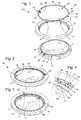
- la
figure 1 représente, de façon schématisée, en perspective éclatée, une variante particulière d'un sous-ensemble d'habillage selon l'invention, comportant un premier composant qui est une carrure, sous laquelle est représenté un deuxième composant qui est un fond, comportant une flèche indiquant une direction d'indexage angulaire, et présenté pour sa fixation en mode baïonnette au premier composant, et un troisième composant qui est une bague élastique destiné à être inséré entre les deux autres ; - la
figure 2 représente, de façon similaire à lafigure 1 , le même sous-ensemble après insertion en appui du deuxième composant sur le premier composant, avec le troisième composant monté solidaire angulairement du premier composant, dans une première orientation angulaire relative correspondant au libre passage de la baïonnette; - la
figure 3 représente, de façon similaire à lafigure 2 , le même sous-ensemble, dans une position fermée suite à fermeture de la baïonnette, après une autre rotation achevée par l'indexage angulaire relatif parfait du deuxième composant par rapport au premier composant, dans une deuxième orientation angulaire ; - la
figure 4 est une vue partielle, en perspective, dans la position de lafigure 3 , de ce sous-ensemble d'habillage, où un relief du deuxième composant est en appui sur une ondulation que comporte une zone déformable du troisième composant; - la
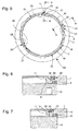
figure 5 est une vue en plan du même sous-ensemble, dans la position indexée de lafigure 3 ; - la
figure 6 est une coupe transversale selon le plan de coupe AA de lafigure 5 ; - la
figure 7 est une coupe transversale selon le plan de coupe BB de lafigure 5 ; - les
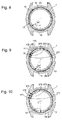
figures 8 à 10 représentent, en vue en plan et de dessus, une autre variante de sous-ensemble selon l'invention : - la
figure 8 en position d'entrée d'insertion de la baïonnette, similaire à celle de lafigure 2 ; - la
figure 9 après une première rotation relative entre le premier composant et le deuxième composant, où une rampe de ce dernier vient en appui sur une zone déformable du troisième composant, avant franchissement de trois crans; - la
figure 10 après une deuxième rotation relative entre le premier composant et le deuxième composant, où la rampe a effectué le franchissement des trois crans, et où le premier composant et le deuxième composant sont dans leur position d'indexage, le fond étant complètement fermé sur la carrure; - la
figure 11 est, pour une variante particulière de l'invention, un exemple de diagramme de consommation de couple en ordonnée, en fonction de l'angle relatif entre le premier composant et le deuxième composant, en abscisse, en trait fort pour la réalisation desfigures 8 à 10 , en comparaison avec un diagramme équivalent en trait interrompu correspondant à la fin de la course de vissage d'une fermeture usuelle non sécurisée d'un fond vissé usuel de l'art antérieur; - la
figure 12 représente, de façon schématisée et en vue de dessous, une montre comportant un tel sous-ensemble dont une carrure constitue le premier composant, et un fond constitue le deuxième composant ; - la
figure 13 représente, de façon schématisée et en vue de dessus, une montre comportant un tel sous-ensemble dont une carrure constitue le premier composant, et une lunette constitue le deuxième composant ; - la
figure 14 représente, de façon schématisée et en vue de dessus, une montre comportant un tel sous-ensemble dont un tube fixé à une carrure constitue le premier composant, et une couronne constitue le deuxième composant.
- the
figure 1 schematically represents, in exploded perspective, a particular variant of a dressing subassembly according to the invention, comprising a first component which is a middle part, under which is represented a second component which is a bottom, comprising a an arrow indicating an angular indexing direction, and presented for its bayonet attachment to the first component, and a third component which is an elastic ring intended to be inserted between the two others; - the
figure 2 represents, similarly to thefigure 1 , the same subassembly after insertion in support of the second component on the first component, with the third component mounted angularly integral with the first component, in a first relative angular orientation corresponding to the free passage of the bayonet; - the
figure 3 represents, similarly to thefigure 2 , the same subassembly, in a closed position following closure of the bayonet, after another rotation completed by the relative relative angular indexing of the second component relative to the first component, in a second angular orientation; - the
figure 4 is a partial view, in perspective, in the position of thefigure 3 of this dressing subassembly, wherein a relief of the second component bears on a corrugation that comprises a deformable zone of the third component; - the
figure 5 is a plan view of the same subset, in the indexed position of thefigure 3 ; - the
figure 6 is a cross-section along the section plane AA of thefigure 5 ; - the
figure 7 is a cross-section along the sectional plane BB of thefigure 5 ; - the
Figures 8 to 10 represent, in plan view and from above, another variant of a subassembly according to the invention: - the
figure 8 in bayonet insertion input position, similar to that of thefigure 2 ; - the
figure 9 after a first relative rotation between the first component and the second component, where a ramp of the latter is supported on a deformable zone of the third component, before crossing three notches; - the
figure 10 after a second relative rotation between the first component and the second component, where the ramp has crossed the three notches, and wherein the first component and the second component are in their indexing position, the bottom being completely closed on the middle part ; - the
figure 11 is, for a particular variant of the invention, an example of an ordinate torque consumption diagram, as a function of the relative angle between the first component and the second component, in abscissa, in strong line for the realization ofFigures 8 to 10 , in comparison with an equivalent dashed diagram corresponding to the end of the screwing stroke of a conventional unsecured closure of a conventional screwed bottom of the prior art; - the
figure 12 represents schematically and in a view from below, a watch comprising such a subassembly of which a middle part constitutes the first component, and a bottom constitutes the second component; - the
figure 13 represents schematically and in top view, a watch comprising such a subset including a middle part constitutes the first component, and a bezel constitutes the second component; - the
figure 14 represents schematically and in top view, a watch comprising such a subset, a tube attached to a middle part is the first component, and a ring is the second component.
L'invention se propose de réaliser un assemblage étanche et sécurisé de composants d'habillage avec un indexage angulaire facile à régler, et dans une position garantie, et ceci avec un nombre minimal de composants, et des coûts de fabrication modérés.The invention proposes to achieve a tight and secure assembly of cladding components with easy to adjust angular indexing, and in a guaranteed position, and this with a minimum number of components, and moderate manufacturing costs.
Les
L'invention concerne un sous-ensemble d'habillage 100 pour une pièce d'horlogerie, et plus particulièrement pour une montre, ou pour un bijou, comportant un premier composant 1 comportant des rebords 2 saillant d'une première jupe 6 alternés avec des premiers dégagements, et un deuxième composant 10 comportant des ailes 12 saillant d'une deuxième jupe 11 alternées avec des deuxièmes dégagements 13.The invention relates to a covering
On utilise ici la dénomination générale de sous-ensemble « d'habillage » aussi bien pour une pièce d'horlogerie que pour un bijou, même si ce terme est d'emploi courant en horlogerie seulement. On comprend que, dans le cas de la bijouterie, ce sous-ensemble peut concerner la structure du bijou, ou des éléments rapportés sur une structure de base, ou tout assemblage de plusieurs composants élémentaires ou pré-assemblés, voire le bijou tout entier.The general denomination of "dressing" sub-assembly is used here as well for a timepiece as for a jewel, even if this term is of current use in watchmaking only. It is understood that, in the case of jewelery, this subset may relate to the structure of the jewel, or elements reported on a basic structure, or any assembly of several elementary or pre-assembled components, or the entire jewel.
Ce sous-ensemble d'habillage 100 est agencé pour passer d'une première position démontée d'insertion, à une deuxième position assemblée et verrouillée.This
Dans la première position démontée d'insertion, le premier composant 1 et le deuxième composant 10 ont l'un par rapport à l'autre une première orientation angulaire.In the first disassembled insertion position, the
Dans une variante particulière, non limitative, comportant des moyens de répulsion agencés au niveau de l'interface entre le premier composant 1 et le deuxième composant 10, ces derniers tendent à être maintenus à distance l'un de l'autre par des moyens de répulsion, lesquels comportent des moyens de répulsion magnétique et/ou au moins un élément élastique et/ou au moins un joint d'étanchéité 9. Le passage de la première position démontée d'insertion à la deuxième position assemblée et verrouillée est effectué sous l'action d'efforts exercés par un opérateur: un effort axial pour surmonter l'effort résistant des moyens de répulsion et mettre au contact le premier composant 1 et le deuxième composant 10, et un couple pour les amener dans une position d'indexation angulaire.In a particular, non-limiting variant, comprising repulsion means arranged at the interface between the
Dans la deuxième position assemblée et verrouillée, le premier composant 1 et le deuxième composant 10 ont l'un par rapport à l'autre une deuxième orientation angulaire différente de la première orientation angulaire. Dans la variante particulière comportant des moyens de répulsion, le premier composant 1 et le deuxième composant 10 sont maintenus axialement à l'encontre de l'effort résistant exercé par ces moyens de répulsion, par l'effet d'un ajustement à baïonnette, réalisé par l'application des efforts axiaux et de couple imprimés par l'opérateur, entre au moins deux rebords 2 et au moins deux ailes 12.In the second assembled and locked position, the
Cette solidarisation du premier composant 1 et du deuxième composant 10, par ajustement à baïonnette, notamment autour d'une direction axiale D, est réversible, et autorise leur démontage. De façon propre à l'invention et en rupture avec l'art antérieur, ce démontage nécessite de la part d'un opérateur des efforts similaires à ceux exercés lors de l'assemblage, ce démontage nécessite de préférence l'utilisation d'un outil spécial, coopérant par exemple avec des trous ou des encoches périphériques, ou similaire, et ne peut être consécutif à une maladresse ni à l'exposition à des facteurs physiques externes particuliers.This joining of the
Selon l'invention, ce sous-ensemble d'habillage 100 comporte au moins un troisième composant 20, qui est agencé pour être intercalé radialement, ou respectivement axialement, entre le premier composant 1 et le deuxième composant 10 et fixe en rotation par rapport à l'un d'entre eux, et qui comporte au moins une zone 50 déformable élastiquement radialement, ou respectivement axialement.According to the invention, this covering
Ce troisième composant 20 est inséré ponctuellement, ou bien au niveau de surfaces étendues, il peut prendre différentes formes, notamment une forme de secteur annulaire ou de bague comme dans la variante non limitative illustrée.This
Cette zone déformable 50 est agencée pour opposer un couple résistant de moment variable à tout couple tangentiel relatif entre le premier composant 1 et ledit deuxième composant 10. Cette zone déformable 50 comporte au moins un cran 26, qui est agencé pour coopérer avec au moins un relief complémentaire 18 que comporte celui des composants 1, 10, par rapport auquel le troisième composant 20 est libre en rotation. Et tout passage d'un tel cran 26 sur un relief complémentaire 18 génère un couple résistant qui tend à s'opposer au mouvement relatif de rotation entre le premier composant 1 et le deuxième composant 10, au moins un tel cran 26 étant agencé pour l'indexage angulaire relatif entre le premier composant 1 et le deuxième composant 10.This
Plus particulièrement, dans une variante particulière non limitative comportant des moyens de répulsion, et illustrée par les figures, l'invention concerne un sous-ensemble d'habillage 100 pour pièce d'horlogerie ou montre, comportant au moins un joint d'étanchéité 9 entre un premier composant 1 et un deuxième composant 10. Dans cette variante particulière, le premier composant 1 comporte des rebords 2 saillant radialement vers l'intérieur d'une première jupe 6, qui sont alternés avec des premiers dégagements 3. Le deuxième composant 10 comporte des ailes 12 saillant radialement vers l'extérieur d'une deuxième jupe 11, qui sont alternées avec des deuxièmes dégagements 13. Ce sous-ensemble d'habillage 100 est alors agencé pour passer d'une position démontée à une position assemblée en compression du joint d'étanchéité 9, par la solidarisation réversible du premier composant 1 et du deuxième composant 10, par un ajustement à baïonnette entre au moins deux rebords 2 et au moins deux ailes 12, dans un mouvement de rotation relatif autour d'une direction axiale D. Si la compression axiale du joint d'étanchéité 9 est la plus classique, l'invention permet aussi sans difficulté un assemblage avec compression radiale d'un tel joint.More particularly, in a particular non-limiting variant comprising means of repulsion, and illustrated by the figures, the invention relates to a subassembly of dressing 100 for a timepiece or watch, comprising at least one
On comprend que l'invention est illustrée ici dans une variante particulière, avec des rebords et des ailes saillant radialement. L'invention est aussi applicable à d'autres variantes où les configurations axiale et radiale sont inversées.It is understood that the invention is illustrated here in a particular variant, with flanges and radially projecting flanges. The invention is also applicable to other variants where the axial and radial configurations are reversed.
Le sous-ensemble d'habillage 100 comporte ainsi au moins un troisième composant 20, qui est agencé pour être intercalé radialement dans la variante illustrée par les figures, entre le premier composant 1 et le deuxième composant 10. Ce troisième composant 20 est fixe en rotation par rapport au premier composant 1 ou au deuxième composant 10. Le troisième composant 20 qui comporte au moins une zone 50 déformable élastiquement, notamment radialement dans la variante des figures. Cette zone déformable 50 est agencée pour opposer un couple résistant de moment variable à tout couple tangentiel relatif entre le premier composant 1 et le deuxième composant 10.The dressing
Ce troisième composant 20 présente l'effet élastique escompté, rapporté ou inséré dans le premier composant 1 ou dans le deuxième composant 10. De façon préférée mais non limitative, il est au moins partiellement annulaire, en secteur annulaire, ou encore en forme de bague fermée comme sur les figures, ou de bague fendue, ou similaire.This
De préférence, la zone déformable 50 comporte au moins un cran 26, qui est agencé pour coopérer avec au moins un relief complémentaire 18 que comporte celui des composants 1, 10, par rapport auquel le troisième composant 20 est libre en rotation. L'agencement relatif des composants du sous-ensemble 100 est tel que tout passage d'un tel cran 26 sur un tel relief complémentaire 18 génère un couple résistant, qui tend à s'opposer au mouvement relatif de rotation entre le premier composant 1 et le deuxième composant 10. Au moins un tel cran 26 est agencé pour l'indexage angulaire relatif entre le premier composant 1 et le deuxième composant 10. Plus particulièrement le couple formé par un cran 26 particulier et un relief complémentaire 18 particulier correspond à l'exercice d'un effort résistant maximal, et ce couple particulier correspond à une position préférentielle d'indexage et de blocage en position indexée.Preferably, the
Plus particulièrement, ce troisième composant 20 est une bague fermée, sensiblement torique.More particularly, this
Dans une réalisation particulière non limitative, le troisième composant 20 est réalisé complètement en matériau élastique.In a particular non-limiting embodiment, the
Plus particulièrement, le premier composant 1 comporte au moins un logement 6 d'arrêt d'un ergot anti-rotation 29 que comporte le troisième composant 20.More particularly, the
Naturellement, la configuration peut être inversée, avec un logement d'arrêt présent dans le deuxième composant 10.Naturally, the configuration can be reversed, with a stop housing present in the
Plus particulièrement, la zone déformable 50 comporte une pluralité de crans 26, qui sont agencés pour opposer une résistance successive à un relief complémentaire 18. Plus particulièrement encore, dans une même telle zone déformable 50, les crans 26 successifs sont agencés pour opposer une résistance croissante à un relief complémentaire 18, lors de la croissance de l'angle relatif entre le premier composant 1 et le deuxième composant 10.More particularly, the
On comprend que l'effort résistant peut être d'autant plus important que le nombre de crans 26 et de reliefs complémentaires 18 en coopération est élevé. Il est donc possible de jouer sur le nombre de crans successifs, et/ou sur la hauteur de chaque cran, ou, plus exactement, l'effort résistant au passage de chaque cran.It is understood that the resistant force can be all the more important as the number of
Lors de l'assemblage, l'utilisateur imprime un couple progressif pour imprimer la rotation relative entre le premier composant 1 et le deuxième composant 10. Après l'insertion du deuxième composant 10 dans le premier composant 1 en enfermant chaque joint 9, dans la position de la
Dans un premier cas de figure, le premier cran 26 et le premier relief complémentaire 18 sont uniques (ou bien sont chacun remplacé par une pluralité de tels couples, de profil et de résistance identique, et disposés en périphérie du profil de façon à interférer en même temps: ce qui revient à un cran résultant unique, et un relief unique ; cette possibilité de duplication de profils en phase n'est pas exposée plus en détail, et est applicable à toute variante de l'invention). Dans ce premier cas, l'effort axial appliqué minimal correspond nécessairement à la mise en étanchéité du ou des joints d'étanchéité 9. Et cette position unique de coopération, le premier cran 26 et le premier relief complémentaire 18 constituent le logement 6 et l'ergot 29 pour l'indexage en position angulaire du deuxième composant 10 par rapport au premier composant 1. Par exemple, trois crans à 120° coopèrent avec des reliefs complémentaires eux aussi à 120°, l'opérateur ressent un seul passage de point dur lorsque les trois crans à 120° agissent simultanément.In a first case, the
Dans un deuxième cas de figure, le sous-ensemble 100 comporte plusieurs crans 26 et plusieurs reliefs complémentaires 18, agencés relativement les uns par rapport aux autres pour que, au début de la rotation relative, un seul couple dégagement-bossage soit en coopération, puis, après un certain angle, deux couples dégagement-bossage soient en coopération simultanée, et ainsi de suite, le sommet de couple résistant cumulé augmentant lors de chaque passage de point dur, pour atteindre, à l'angle d'indexage, la valeur maximale. L'opérateur rencontre ainsi une sensation de résistance croissante.In a second case, the
L'étanchéité existe dès la mise en baïonnette, et le mécanisme selon l'invention est agencé pour que, comme dans le cas précédent d'une bosse unique, la mise en sécurité de l'étanchéité du ou des joints d'étanchéité 9 soit assurée dès le passage de cette première bosse, puisqu'alors aucun desserrage ne peut se produire sans action volontaire d'un opérateur.The seal exists as soon as the bayonet is set, and the mechanism according to the invention is arranged so that, as in the previous case of a single bump, the sealing of the seal (s) 9 is made safe. ensured from the passage of this first bump, since then no loosening can occur without voluntary action of an operator.
Dans la pratique, de très bons résultats sont obtenus avec au moins deux, et de préférence trois, voire quatre, bosses successives, de préférence sans dépasser cinq, de façon à procurer une course angulaire élémentaire suffisante pour le passage de chaque bosse. Un bon exemple pratique comporte trois ensembles en phase, correspondant chacun à trois bosses.In practice, very good results are obtained with at least two, and preferably three or even four, successive bumps, preferably not exceeding five, so as to provide an elementary angular stroke sufficient for the passage of each bump. A good practical example has three sets in phase, each corresponding to three bumps.
La
De plus, la valeur angulaire θV correspondant au vissage maximal avec un couple γV correspond à la fin d'une courbe de croissance de couple, dont la pente devient extrêmement raide au voisinage de cette valeur θV : ce qui signifie qu'un sous-ensemble vissé qui est alors soumis à un effort important risque de se dévisser, sans aucun garde-fou pour empêcher un dévissage total, ni la perte d'étanchéité, puisque le couple nécessaire au dévissage est alors dégressif, et l'énergie à fournir pour le dévissage plus faible que dans le cas de l'invention.Moreover, the angular value θV corresponding to the maximum screwing with a pair γV corresponds to the end of a torque growth curve, whose slope becomes extremely steep in the vicinity of this value θV: which means that a subset screw which is then subjected to a large force may be unscrewed, without any guard to prevent a total unscrewing, or loss of sealing, since the torque required for unscrewing is then decreasing, and the energy to be provided for the looser than in the case of the invention.
Dans une autre variante encore, non illustrée, une même bosse coopère successivement avec plusieurs dégagements, qui peuvent être chacun de même profondeur dans une réalisation particulière, créant alors une valeur d'effort résistant fixe, et qu'il faut passer à plusieurs reprises pour arriver en position fermée et indexée. Il est, encore, possible de panacher ces deux dernières variantes, tout est possible, les usinages à réaliser étant peu complexes.In yet another variant, not illustrated, a same boss cooperates successively with several clearances, which may each be of the same depth in a particular embodiment, then creating a fixed resistance force value, and which must be repeatedly passed for arrive in closed and indexed position. It is still possible to mix these last two variants, everything is possible, the machining to be made is not very complex.
Au contraire, l'invention nécessite, lors de l'assemblage, le franchissement successif, dans une sorte de rampe, de plusieurs bosses de couple de résistance croissante, mais aussi au démontage, car, depuis la position finale indexée θM, notamment sur une éventuelle butée mécanique (qui n'est toutefois pas nécessaire dans le cadre de l'invention), toute application d'un effort soudain se traduit, dans le pire des cas, par le franchissement d'une seule bosse, sans désassemblage total, avec un décalage visuel, et surtout sans perte d'étanchéité ni risque de pollution de l'intérieur de la montre. Dans l'exemple illustré l'opérateur doit franchir successivement trois seuils, visible optiquement en raison du décalage, avant d'avoir une perte d'étanchéité.On the contrary, the invention requires, during the assembly, the successive crossing, in a kind of ramp, of several bumps of increasing resistance torque, but also the disassembly, since, since the final indexed position θM, in particular on a mechanical stop (which is however not necessary in the context of the invention), any application of a sudden effort is reflected in the worst case, by crossing a single bump, without total disassembly, with a visual shift, and especially without loss of sealing or risk of pollution of the interior of the watch. In the illustrated example, the operator must successively cross three thresholds, visible optically because of the offset, before having a leakage loss.
Dans un cas particulier, chaque cran est identique, et son passage oppose un même couple résistant.In a particular case, each notch is identical, and its passage opposes the same resistant torque.
Dans une variante avantageuse, plusieurs crans se succèdent, et l'opérateur doit appliquer un couple croissant, comme dans l'exemple des trois crans de la
L'invention est avantageuse car parfaitement compatible avec des dimensions horlogères, tout en ayant une capacité d'un effort résistant élevé, qui peut atteindre plusieurs N.m, par exemple dans le cas d'un troisième composant en matériau métallique au moins partiellement amorphe. Même avec des matériaux plus courants pour la fabrication de bagues techniques, POM, polyuréthane ou similaire, et des dimensions axiales et radiales de quelques dixièmes de millimètre, le couple résistant excède facilement un N.m.The invention is advantageous because it is perfectly compatible with horological dimensions, while having a capacity of a high resistance force, which can reach several Nm, for example in the case of a third component of at least partially amorphous metallic material. Even with more common materials for the manufacture of technical rings, POM, polyurethane or similar, and axial and radial dimensions of a few tenths of a millimeter, the resistant torque easily exceeds one N.m.
D'ailleurs, dans le cas où la pièce d'horlogerie ou de bijouterie est soumise à des contraintes particulières de grande ampleur, le démontage du mécanisme selon l'invention nécessite le maintien de l'application d'un éventuel effort d'origine accidentelle pendant une course angulaire importante, de 7 à 8° pour le franchissement d'une seule bosse dans l'exemple illustré, la sécurité restant encore assurée si plusieurs bosses se succèdent, alors que, en solution vissée de l'art antérieur, le démontage est consommé dans une course angulaire de l'ordre de 2° seulement, et donc la perte d'étanchéité également.Moreover, in the case where the timepiece or jewelery is subjected to particular constraints of great magnitude, the disassembly of the mechanism according to the invention requires the maintenance of the application of a possible effort of accidental origin during a large angular stroke, from 7 to 8 ° for the crossing of a single bump in the illustrated example, the security still being ensured if several bumps succeed one another, whereas, in screwed solution of the prior art, the dismantling is consumed in an angular stroke of the order of 2 ° only, and therefore the loss of tightness also.
Dans une variante, l'indexage angulaire peut être garanti par une butée 28 de limitation de course. Mais, de préférence, c'est le troisième composant 20 qui remplit, de facto, la fonction de butée, par l'exercice d'un couple résistant particulièrement élevé. Une telle butée mécanique n'est de ce fait pas absolument nécessaire.Alternatively, the angular indexing can be guaranteed by a
L'invention permet, ainsi, de prévenir tout démontage inopiné et involontaire du sous-ensemble 100, par exemple sous l'effet de vibrations, de cycles de dilatation successifs, par une utilisation malencontreuse de l'utilisateur, ou autre.The invention thus makes it possible to prevent any unexpected and involuntary disassembly of the
De façon préférée, le démontage nécessite un outil spécial non commercialisé, ce qui assure l'exécution de la maintenance par du personnel d'après-vente possédant les qualifications requises.Preferably, the disassembly requires a special non-commercial tool, which ensures the execution of maintenance by aftersales staff having the required qualifications.
Les figures illustrent différentes variantes nullement limitatives.The figures illustrate various non-limiting variants.
Les
Les
L'invention se prête bien aux cas où le sous-ensemble 100 comporte des composants 1 et 10 réalisés dans des matériaux différents, avec des coefficients de dilatation différents, ou encore des matières fragiles, ou dures (céramique, saphir), qui n'autorisent pas des modes de fixation standard. Citons parmi des configurations classiques l'assemblage d'une carrure en or avec un fond saphir, ou encore une boîte entièrement en céramique, une combinaison métal-céramique, ou similaires.The invention is well suited to cases where the
Le troisième composant 20 est de préférence une bague, qui peut être réalisée en différents matériaux , notamment POM, polyuréthane, matière à base polymère, ou élastomère, alliage métallique au moins partiellement amorphe, le matériau choisi déterminant le couple de serrage maximal, ainsi une bague en alliage amorphe autorise un couple de serrage d'environ 3.2 N.m, similaire à celui usuel d'un fond vissé sur une carrure, pour un joint 9 de même taille. Cette bague peut encore être réalisée en métal amorphe, inox, CuBe, « Liquidmetal© », voire être bi-matériaux, par exemple avec une âme en matériau plastique avec des inserts surmoulés, métalliques, ou en céramique, ou autre. L'intérêt d'une telle bague, de préférence dans un matériau élastique polymère ou similaire, est sa facilité de logement dans un volume dont l'espace libre est très limité, où il est impossible d'implanter en toute sécurité un élément métallique susceptible de casser.The
Naturellement, le matériau du troisième composant 20 peut aussi être plus complexe, notamment sous la forme d'une matière de type élastomère chargée avec des fibres techniques telles que « Kevlar® » ou similaire, ou avec un additif anti-usure tel que polytétrafluoroéthylène dit PTFE, ou autre.Naturally, the material of the
Un avantage important de l'invention est de nécessiter ni perçage ni taraudage, mais uniquement des usinages simples réalisables avec une certaine facilité, évitant ainsi toute salissure ou pollution de la montre, et autorisant un coût modéré.An important advantage of the invention is to require neither drilling nor tapping, but only simple machining achievable with a certain ease, thus avoiding any soiling or pollution of the watch, and allowing a moderate cost.
Plus particulièrement, et tel que visible sur les
On note, à ce propos, que l'invention peut être mise en oeuvre sans de tels moyens de répulsion, notamment pour des applications d'habillage ou similaire.It should be noted, in this connection, that the invention can be implemented without such repulsion means, in particular for cladding applications or the like.
Dans une autre application, le premier composant 1 est une carrure et le deuxième composant 10 est un réhaut ou une lunette, tel que visible sur la
Dans une autre application encore, le premier composant 1 est une carrure ou un tube rapporté sur une carrure, et le deuxième composant 10 est une couronne, tel que visible sur la
L'invention est apte à de nombreuses applications en horlogerie, par exemple pour une valve hélium sur une montre de plongée, ou encore pour des composants d'habillage tels qu'un bracelet, une boucle, un fermoir, ou autre. Il en est de même en bijouterie, pour effectuer la fermeture de boutons de manchette, de boucles d'oreilles, ou encore pour fixer des pierreries ou des éléments décorés conçus de manière amovible.The invention is suitable for many applications in watchmaking, for example for a helium valve on a diving watch, or for dressing components such as a bracelet, a buckle, a clasp, or other. It is the same in jewelry, for closing cufflinks, earrings, or for securing precious stones or decorated elements removably designed.
L'invention concerne encore une pièce d'horlogerie ou montre 1000 comportant un tel sous-ensemble d'habillage 100.The invention also relates to a timepiece or watch 1000 comprising such a
L'invention concerne encore un bijou comportant un tel sous-ensemble 100.The invention also relates to a jewel comprising such a
En somme, l'invention permet de disposer d'un sous-ensemble à assemblage à baïonnette, avec une bague de maintien montée sur un premier composant, notamment une bague sensiblement torique. Cette bague peut aussi être ouverte, par exemple avec une fente comme un circlips ou similaire, pour faciliter le montage. Lors de la rotation relative du deuxième composant par rapport au premier composant, des encoches du deuxième composant viennent se bloquer avec des encoches de la bague. Cette conception est peu encombrante, elle assure le maintien de l'étanchéité de la montre, qu'elle protège contre tout démontage accidentel.In sum, the invention makes it possible to have a subassembly with a bayonet connection, with a retaining ring mounted on a first component, in particular a substantially toroidal ring. This ring can also be opened, for example with a slot like a circlip or the like, to facilitate assembly. During the relative rotation of the second component relative to the first component, notches of the second component come to lock with notches of the ring. This design is compact, it maintains the seal of the watch, it protects against accidental disassembly.
L'invention permet d'assurer l'orientation parfaite d'un composant maintenu bloqué dans sa position de service.The invention makes it possible to ensure the perfect orientation of a locked component in its operating position.
Quand le sous-ensemble selon l'invention remplit une fonction de fermeture d'un fond ou similaire, il procure de nombreux avantages :
- à partir d'une première position angulaire relative, entre le premier composant et le deuxième composant, où la fonction d'étanchéité est assurée, par exemple dès que la compression d'un joint d'étanchéité est effectuée, il existe, dans le mécanisme selon l'invention, un domaine élargi de valeurs angulaires relatives entre ce premier composant et ce deuxième composant, dans lequel l'étanchéité reste garantie, par exemple de plusieurs dizaines de degrés, ce qui est important en comparaison avec par exemple un fond vissé standard dans le cas d'un sous-ensemble carrure-fond, où un dévissage de quelques degrés seulement (moins de dix degrés) entraîne la perte d'étanchéité et la nécessité d'une remise en propreté et d'une nouvelle de revendication, alors que selon l'invention ce n'est qu'après le passage du tout dernier cran lors du démontage que la perte d'étanchéité devient possible si l'on poursuit la rotation;
- une fermeture par succession de crans qui présente un couple de fermeture du fond largement dimensionné, à la fois suffisant et acceptable pour un tel montage, grâce en particulier à la multiplication du nombre de bosses réparties sur la circonférence, avec, pour l'opérateur, une sensation de vissage par étapes d'augmentation du couple de fermeture jusqu'à la position désirée, réputée être la position fermée, qui est aussi bien perceptible ;
- une sécurité d'ouverture, qui est augmentée par deux facteurs : la nécessité pour l'opérateur de fournir une énergie positive importante pour passer un cran ; et le passage successif de plusieurs crans préalable à toute perte d'étanchéité.
- from a first relative angular position, between the first component and the second component, where the sealing function is ensured, for example as soon as the compression of a seal is performed, there is, in the mechanism according to the invention, an enlarged range of relative angular values between this first component and this second component, in which the sealing remains guaranteed, for example by several tens of degrees, which is important in comparison with, for example, a standard screwed bottom in the case of a middle-to-back subassembly, where a unscrewing of only a few degrees (less than ten degrees) results in the loss of watertightness and the need for a cleanup and a new claim, then that according to the invention it is only after the passage of the very last notch during disassembly that the loss of tightness becomes possible if one continues the rotation;
- a succession of notches closure which has a large dimensionally closed bottom closure torque, both sufficient and acceptable for such an assembly, thanks in particular to the multiplication of the number of bumps distributed over the circumference, with, for the operator, a tightening sensation in steps of increasing the closing torque to the desired position, deemed to be the closed position, which is also noticeable;
- an opening security, which is increased by two factors: the need for the operator to provide significant positive energy to pass a notch; and the successive passage of several notches prior to any leakage.
L'invention autorise, encore, la mise en coopération de composants antagonistes réalisés en matières de différentes natures, sans contrainte de dilatation frottement, élasticité, ou autre, sans nécessiter d'élément de fixation extérieur tel que vis ou similaire, sans pas de vis ni usinage risquant de fragiliser des matières particulières telles que céramiques, saphir, et similaires. Elle présente une très bonne résistance à un dévissage accidentel ou même volontaire par vibration ou du type Chapuis-chocs. L'invention permet aussi d'assurer l'interchangeabilité des composants, et, par conséquent, une personnalisation accrue des montres ou des bijoux des utilisateurs.The invention also authorizes the cooperation of antagonistic components made of different materials, without expansion stress friction, elasticity, or other, without requiring external fastening element such as screw or the like, without screws nor machining may weaken particular materials such as ceramics, sapphire, and the like. It has a very good resistance to accidental or even voluntary unwinding by vibration or Chapuis-choc type. The invention also makes it possible to ensure the interchangeability of the components, and, consequently, an increased personalization of the watches or jewels of the users.
Cette invention est applicable aussi bien à des montres ou bijoux réalisés en matériaux précieux qu'à des réalisations de grande série comportant des composants de faible coût unitaire, notamment en matière plastique ou similaire.This invention is applicable both to watches or jewelery made of precious materials that large series of achievements comprising low unit cost components, including plastic or similar.
L'invention se prête bien aux cas où le sous-ensemble 100 comporte des composants 1 et 10 réalisés dans des matériaux différents, avec des coefficients de dilatation différents, ou encore des matières fragiles, ou dures (céramique, saphir, pierres précieuses, gemmes, camées), qui n'autorisent pas des modes de fixation standard. Citons parmi des configurations classiques l'assemblage d'une carrure en or avec un fond saphir, ou encore une boîte entièrement en céramique, une combinaison métal-céramique, ou similaires. Les composants 1 et 10 peuvent ainsi être réalisés en toutes sortes de matériaux : alliages métalliques, notamment précieux ou titrés, aciers inoxydables, alliages métalliques au moins partiellement amorphe, ou « Liquidmetal© » ou similaire, céramiques, saphir, minéraux, pierres dures, caoutchouc, matières plastiques et notamment élastomères thermoplastiques dits TPE dont notamment polyuréthane thermoplastique dit TPU, polycarbonates dits PC, chlorures de polyvinyle dits PVC, polyacétals ou polyoxyméthylène dit POM, silicone, « Nylon® », pour ne citer, non limitativement, que des matériaux usuels en construction horlogère et en bijouterie-joaillerie.The invention is well suited to cases where the
Claims (16)
Priority Applications (6)
| Application Number | Priority Date | Filing Date | Title |
|---|---|---|---|
| EP16181139.3A EP3276432B1 (en) | 2016-07-26 | 2016-07-26 | Casing subassembly for a timepiece, watch or jewel |
| CH00965/16A CH712740B1 (en) | 2016-07-26 | 2016-07-26 | Sub-assembly of a covering for a timepiece, in particular a watch, or for a piece of jewelry. |
| US15/654,056 US10088806B2 (en) | 2016-07-26 | 2017-07-19 | Exterior sub-assembly for a timepiece or watch or piece of jewellery |
| JP2017141708A JP6453949B2 (en) | 2016-07-26 | 2017-07-21 | Exterior subassemblies for watches or watches or jewelry |
| CN201710610745.3A CN107656434B (en) | 2016-07-26 | 2017-07-25 | External subassembly for a timepiece or watch or a jewellery item |
| HK18109022.3A HK1249593A1 (en) | 2016-07-26 | 2018-07-11 | Exterior sub-assembly for a timepiece or watch or piece of jewellery |
Applications Claiming Priority (1)
| Application Number | Priority Date | Filing Date | Title |
|---|---|---|---|
| EP16181139.3A EP3276432B1 (en) | 2016-07-26 | 2016-07-26 | Casing subassembly for a timepiece, watch or jewel |
Publications (2)
| Publication Number | Publication Date |
|---|---|
| EP3276432A1 true EP3276432A1 (en) | 2018-01-31 |
| EP3276432B1 EP3276432B1 (en) | 2020-03-25 |
Family
ID=56550756
Family Applications (1)
| Application Number | Title | Priority Date | Filing Date |
|---|---|---|---|
| EP16181139.3A Active EP3276432B1 (en) | 2016-07-26 | 2016-07-26 | Casing subassembly for a timepiece, watch or jewel |
Country Status (6)
| Country | Link |
|---|---|
| US (1) | US10088806B2 (en) |
| EP (1) | EP3276432B1 (en) |
| JP (1) | JP6453949B2 (en) |
| CN (1) | CN107656434B (en) |
| CH (1) | CH712740B1 (en) |
| HK (1) | HK1249593A1 (en) |
Cited By (5)
| Publication number | Priority date | Publication date | Assignee | Title |
|---|---|---|---|---|
| CN110308637A (en) * | 2018-03-20 | 2019-10-08 | 奥米加股份有限公司 | Ring rotation watch rim system including ring spring |
| CN110308639A (en) * | 2018-03-20 | 2019-10-08 | 奥米加股份有限公司 | Ring rotation watch rim system including at least one elastic arm |
| EP3936732A1 (en) | 2020-07-10 | 2022-01-12 | Rolex Sa | Threaded timepiece member |
| CH718418A1 (en) * | 2021-03-10 | 2022-09-15 | Mft Dhorlogerie Audemars Piguet Sa | Case element for a timepiece comprising a solid metal glass pusher. |
| EP4109181A1 (en) * | 2021-06-21 | 2022-12-28 | ETA SA Manufacture Horlogère Suisse | Dial, watch comprising such a dial and method for installing such a dial in a watch |
Families Citing this family (13)
| Publication number | Priority date | Publication date | Assignee | Title |
|---|---|---|---|---|
| EP3674815B1 (en) * | 2018-12-27 | 2021-09-29 | Omega SA | Watch case provided with an annular ring and wristwatch and kit for assembling a wristwatch comprising same |
| EP3680729B1 (en) * | 2019-01-09 | 2024-04-24 | Blancpain SA | Rotatably adjustable back for a clock piece |
| EP3699695B1 (en) * | 2019-02-25 | 2022-07-06 | Comadur S.A. | Multi-decor and/or multi-colour clock piece component with ceramic structure |
| EP3712715A1 (en) * | 2019-03-18 | 2020-09-23 | Montres Breguet S.A. | Watch case comprising a rotating bezel |
| JP6924417B2 (en) * | 2019-03-25 | 2021-08-25 | カシオ計算機株式会社 | Cases, case manufacturing methods and watches |
| EP3796104B1 (en) | 2019-09-20 | 2022-04-20 | The Swatch Group Research and Development Ltd | Casing subassembly for a timepiece, watch or jewel |
| EP3796106B1 (en) * | 2019-09-20 | 2022-06-01 | The Swatch Group Research and Development Ltd | Casing subassembly for a timepiece, watch or jewel |
| EP3800514B1 (en) * | 2019-10-04 | 2024-01-17 | Comadur S.A. | Spring ring of a snap fitting of a rotating bezel |
| EP3805869A1 (en) * | 2019-10-09 | 2021-04-14 | Meco S.A. | Threaded crown |
| EP3958068A1 (en) * | 2020-08-17 | 2022-02-23 | The Swatch Group Research and Development Ltd | Device for attaching a back cover on a middle for a clockpiece |
| EP3958067A1 (en) | 2020-08-17 | 2022-02-23 | The Swatch Group Research and Development Ltd | Device for attaching a bottom on a middle for a clockpiece |
| EP4191347A1 (en) * | 2021-12-01 | 2023-06-07 | The Swatch Group Research and Development Ltd | Watch case comprising a bottom oriented in a predetermined angular position |
| EP4194968A1 (en) * | 2021-12-07 | 2023-06-14 | The Swatch Group Research and Development Ltd | Device for attaching and orientating a bottom on a middle for a clockpiece |
Citations (4)
| Publication number | Priority date | Publication date | Assignee | Title |
|---|---|---|---|---|
| EP1431845A1 (en) * | 2002-12-20 | 2004-06-23 | Rolex S.A. | Watchcase |
| EP1835363A1 (en) * | 2006-03-16 | 2007-09-19 | Officine Panerai Branch of Richemont International SA | Timepiece incorporating a rotary bezel |
| EP2672333A1 (en) * | 2012-06-06 | 2013-12-11 | Omega SA | Rotating bezel system |
| EP2672331A1 (en) * | 2012-06-06 | 2013-12-11 | Omega SA | Timepiece case with exterior element with improved attachment |
Family Cites Families (13)
| Publication number | Priority date | Publication date | Assignee | Title |
|---|---|---|---|---|
| CH678862A4 (en) * | 1962-06-05 | 1964-11-14 | ||
| JPS534134Y2 (en) * | 1973-08-30 | 1978-02-01 | ||
| CH617816GA3 (en) * | 1978-05-23 | 1980-06-30 | ||
| JPS57112983U (en) * | 1980-12-30 | 1982-07-13 | ||
| CH690140A5 (en) * | 1996-03-05 | 2000-05-15 | Smh Management Services Ag | watch box with a rotating bezel. |
| JP3712911B2 (en) * | 2000-03-30 | 2005-11-02 | セイコーインスツル株式会社 | Watch case with rotating bezel |
| JP4723784B2 (en) * | 2000-03-30 | 2011-07-13 | セイコーインスツル株式会社 | Watch case with rotating bezel |
| CH696564A5 (en) * | 2001-07-18 | 2007-07-31 | Swatch Group Man Serv Ag | fixing Dispostif a bottom on the middle part of a watchcase to its alignment with respect to a 12H-6H axis. |
| CN101233458A (en) * | 2005-07-29 | 2008-07-30 | 历峰国际有限公司 | Case for screening magnetic fields |
| US9753434B2 (en) * | 2013-06-20 | 2017-09-05 | Citizen Watch Co., Ltd. | Watch |
| US9568808B2 (en) * | 2014-08-07 | 2017-02-14 | Houdinix Llc | Low-profile lens mount |
| EP3002639B1 (en) * | 2014-10-01 | 2018-01-31 | Montres Breguet SA | Musical watch bezel with improved acoustic performance |
| EP3088970A1 (en) * | 2015-04-27 | 2016-11-02 | ETA SA Manufacture Horlogère Suisse | Watch intended for being mounted on a removable support |
-
2016
- 2016-07-26 EP EP16181139.3A patent/EP3276432B1/en active Active
- 2016-07-26 CH CH00965/16A patent/CH712740B1/en unknown
-
2017
- 2017-07-19 US US15/654,056 patent/US10088806B2/en active Active
- 2017-07-21 JP JP2017141708A patent/JP6453949B2/en active Active
- 2017-07-25 CN CN201710610745.3A patent/CN107656434B/en active Active
-
2018
- 2018-07-11 HK HK18109022.3A patent/HK1249593A1/en unknown
Patent Citations (4)
| Publication number | Priority date | Publication date | Assignee | Title |
|---|---|---|---|---|
| EP1431845A1 (en) * | 2002-12-20 | 2004-06-23 | Rolex S.A. | Watchcase |
| EP1835363A1 (en) * | 2006-03-16 | 2007-09-19 | Officine Panerai Branch of Richemont International SA | Timepiece incorporating a rotary bezel |
| EP2672333A1 (en) * | 2012-06-06 | 2013-12-11 | Omega SA | Rotating bezel system |
| EP2672331A1 (en) * | 2012-06-06 | 2013-12-11 | Omega SA | Timepiece case with exterior element with improved attachment |
Cited By (10)
| Publication number | Priority date | Publication date | Assignee | Title |
|---|---|---|---|---|
| CN110308637A (en) * | 2018-03-20 | 2019-10-08 | 奥米加股份有限公司 | Ring rotation watch rim system including ring spring |
| CN110308639A (en) * | 2018-03-20 | 2019-10-08 | 奥米加股份有限公司 | Ring rotation watch rim system including at least one elastic arm |
| CN110308639B (en) * | 2018-03-20 | 2021-08-13 | 奥米加股份有限公司 | Ring-shaped rotary bezel system comprising at least one elastic arm |
| CN110308637B (en) * | 2018-03-20 | 2022-04-08 | 奥米加股份有限公司 | Ring-shaped rotary bezel system comprising a spring ring |
| US11385597B2 (en) | 2018-03-20 | 2022-07-12 | Omega Sa | Annular rotating bezel system comprising a spring ring |
| EP3936732A1 (en) | 2020-07-10 | 2022-01-12 | Rolex Sa | Threaded timepiece member |
| US11880169B2 (en) | 2020-07-10 | 2024-01-23 | Rolex Sa | Threaded timepiece member |
| CH718418A1 (en) * | 2021-03-10 | 2022-09-15 | Mft Dhorlogerie Audemars Piguet Sa | Case element for a timepiece comprising a solid metal glass pusher. |
| EP4071557A1 (en) * | 2021-03-10 | 2022-10-12 | Manufacture d'Horlogerie Audemars Piguet SA | Element of case for a timepiece comprising a solid metallic glass push button |
| EP4109181A1 (en) * | 2021-06-21 | 2022-12-28 | ETA SA Manufacture Horlogère Suisse | Dial, watch comprising such a dial and method for installing such a dial in a watch |
Also Published As
| Publication number | Publication date |
|---|---|
| JP6453949B2 (en) | 2019-01-16 |
| CH712740A2 (en) | 2018-01-31 |
| JP2018017731A (en) | 2018-02-01 |
| CH712740B1 (en) | 2020-08-31 |
| EP3276432B1 (en) | 2020-03-25 |
| CN107656434A (en) | 2018-02-02 |
| CN107656434B (en) | 2020-12-01 |
| HK1249593A1 (en) | 2018-11-02 |
| US10088806B2 (en) | 2018-10-02 |
| US20180032034A1 (en) | 2018-02-01 |
Similar Documents
| Publication | Publication Date | Title |
|---|---|---|
| EP3276432B1 (en) | Casing subassembly for a timepiece, watch or jewel | |
| EP3276187B1 (en) | Casing subassembly for a timepiece, watch or jewel | |
| EP3279745B1 (en) | Adjustable threaded crown | |
| CH705090A2 (en) | Device for adjusting angular orientation of screw-down crown relative to middle of watch, has indexing unit arranged between cover and coupling member of crown, and magnetic return unit to rotatably connect cover and coupling member | |
| EP2182417A2 (en) | Screw crown and method for orienting such a crown on a watch case | |
| EP3574377A1 (en) | Watch case comprising a capsule held in place in a middle by a rear bezel | |
| CH705043A2 (en) | Laptop timepiece including a push button. | |
| WO2020011512A1 (en) | Watch having a rotating bezel with bezel locking system provided with an integrated helium valve | |
| CH714764B1 (en) | Timepiece fitted with a crown. | |
| EP3276433B1 (en) | Casing subassembly for a timepiece, watch or jewel | |
| EP3796104B1 (en) | Casing subassembly for a timepiece, watch or jewel | |
| EP3339966B1 (en) | Push-button for a timepiece | |
| EP3796106B1 (en) | Casing subassembly for a timepiece, watch or jewel | |
| CH712741A2 (en) | Subset of clothing for a timepiece, in particular a watch, or for jewelery. | |
| EP2182416A1 (en) | Device for positioning and mounting a case-back and process for positioning and mounting this case-back on a watch-case. | |
| EP3321749B1 (en) | Seal for timepieces | |
| EP2915445A1 (en) | Device and method for assembling a pivot of at least two parts, corresponding set of two assembled parts | |
| EP4194967A1 (en) | Device for attaching a bottom on a middle for a timepiece | |
| EP3958067A1 (en) | Device for attaching a bottom on a middle for a clockpiece | |
| CH717758A2 (en) | Device for fixing a back to a caseband for a timepiece. | |
| CH719212A2 (en) | Device for fixing a back to a middle part for a timepiece. | |
| EP4174583A1 (en) | Control device for a timepiece | |
| CH718095A2 (en) | Watch comprising a waterproof case housed in an outer case. | |
| EP4256406A1 (en) | Device for assembling two timepiece components | |
| EP4155834A1 (en) | Secure control element for a timepiece |
Legal Events
| Date | Code | Title | Description |
|---|---|---|---|
| PUAI | Public reference made under article 153(3) epc to a published international application that has entered the european phase |
Free format text: ORIGINAL CODE: 0009012 |
|
| STAA | Information on the status of an ep patent application or granted ep patent |
Free format text: STATUS: THE APPLICATION HAS BEEN PUBLISHED |
|
| AK | Designated contracting states |
Kind code of ref document: A1 Designated state(s): AL AT BE BG CH CY CZ DE DK EE ES FI FR GB GR HR HU IE IS IT LI LT LU LV MC MK MT NL NO PL PT RO RS SE SI SK SM TR |
|
| AX | Request for extension of the european patent |
Extension state: BA ME |
|
| STAA | Information on the status of an ep patent application or granted ep patent |
Free format text: STATUS: REQUEST FOR EXAMINATION WAS MADE |
|
| 17P | Request for examination filed |
Effective date: 20180731 |
|
| RBV | Designated contracting states (corrected) |
Designated state(s): AL AT BE BG CH CY CZ DE DK EE ES FI FR GB GR HR HU IE IS IT LI LT LU LV MC MK MT NL NO PL PT RO RS SE SI SK SM TR |
|
| REG | Reference to a national code |
Ref country code: DE Ref legal event code: R079 Ref document number: 602016032416 Country of ref document: DE Free format text: PREVIOUS MAIN CLASS: G04B0019280000 Ipc: G04B0037000000 |
|
| GRAJ | Information related to disapproval of communication of intention to grant by the applicant or resumption of examination proceedings by the epo deleted |
Free format text: ORIGINAL CODE: EPIDOSDIGR1 |
|
| STAA | Information on the status of an ep patent application or granted ep patent |
Free format text: STATUS: GRANT OF PATENT IS INTENDED |
|
| GRAP | Despatch of communication of intention to grant a patent |
Free format text: ORIGINAL CODE: EPIDOSNIGR1 |
|
| RIC1 | Information provided on ipc code assigned before grant |
Ipc: G04B 37/00 20060101AFI20191022BHEP Ipc: G04B 19/28 20060101ALI20191022BHEP Ipc: G04B 37/11 20060101ALI20191022BHEP Ipc: G04B 37/08 20060101ALI20191022BHEP |
|
| INTG | Intention to grant announced |
Effective date: 20191112 |
|
| RIN1 | Information on inventor provided before grant (corrected) |
Inventor name: KNUCHEL, DANIEL Inventor name: VUILLE, PIERRY Inventor name: CATANESE, ROCCO |
|
| GRAS | Grant fee paid |
Free format text: ORIGINAL CODE: EPIDOSNIGR3 |
|
| GRAA | (expected) grant |
Free format text: ORIGINAL CODE: 0009210 |
|
| STAA | Information on the status of an ep patent application or granted ep patent |
Free format text: STATUS: THE PATENT HAS BEEN GRANTED |
|
| AK | Designated contracting states |
Kind code of ref document: B1 Designated state(s): AL AT BE BG CH CY CZ DE DK EE ES FI FR GB GR HR HU IE IS IT LI LT LU LV MC MK MT NL NO PL PT RO RS SE SI SK SM TR |
|
| REG | Reference to a national code |
Ref country code: GB Ref legal event code: FG4D Free format text: NOT ENGLISH |
|
| REG | Reference to a national code |
Ref country code: CH Ref legal event code: NV Representative=s name: ICB INGENIEURS CONSEILS EN BREVETS SA, CH Ref country code: AT Ref legal event code: REF Ref document number: 1249256 Country of ref document: AT Kind code of ref document: T Effective date: 20200415 Ref country code: IE Ref legal event code: FG4D Free format text: LANGUAGE OF EP DOCUMENT: FRENCH |
|
| REG | Reference to a national code |
Ref country code: DE Ref legal event code: R096 Ref document number: 602016032416 Country of ref document: DE |
|
| PG25 | Lapsed in a contracting state [announced via postgrant information from national office to epo] |
Ref country code: RS Free format text: LAPSE BECAUSE OF FAILURE TO SUBMIT A TRANSLATION OF THE DESCRIPTION OR TO PAY THE FEE WITHIN THE PRESCRIBED TIME-LIMIT Effective date: 20200325 Ref country code: FI Free format text: LAPSE BECAUSE OF FAILURE TO SUBMIT A TRANSLATION OF THE DESCRIPTION OR TO PAY THE FEE WITHIN THE PRESCRIBED TIME-LIMIT Effective date: 20200325 Ref country code: NO Free format text: LAPSE BECAUSE OF FAILURE TO SUBMIT A TRANSLATION OF THE DESCRIPTION OR TO PAY THE FEE WITHIN THE PRESCRIBED TIME-LIMIT Effective date: 20200625 |
|
| PG25 | Lapsed in a contracting state [announced via postgrant information from national office to epo] |
Ref country code: BG Free format text: LAPSE BECAUSE OF FAILURE TO SUBMIT A TRANSLATION OF THE DESCRIPTION OR TO PAY THE FEE WITHIN THE PRESCRIBED TIME-LIMIT Effective date: 20200625 Ref country code: HR Free format text: LAPSE BECAUSE OF FAILURE TO SUBMIT A TRANSLATION OF THE DESCRIPTION OR TO PAY THE FEE WITHIN THE PRESCRIBED TIME-LIMIT Effective date: 20200325 Ref country code: SE Free format text: LAPSE BECAUSE OF FAILURE TO SUBMIT A TRANSLATION OF THE DESCRIPTION OR TO PAY THE FEE WITHIN THE PRESCRIBED TIME-LIMIT Effective date: 20200325 Ref country code: LV Free format text: LAPSE BECAUSE OF FAILURE TO SUBMIT A TRANSLATION OF THE DESCRIPTION OR TO PAY THE FEE WITHIN THE PRESCRIBED TIME-LIMIT Effective date: 20200325 Ref country code: GR Free format text: LAPSE BECAUSE OF FAILURE TO SUBMIT A TRANSLATION OF THE DESCRIPTION OR TO PAY THE FEE WITHIN THE PRESCRIBED TIME-LIMIT Effective date: 20200626 |
|
| REG | Reference to a national code |
Ref country code: NL Ref legal event code: MP Effective date: 20200325 |
|
| REG | Reference to a national code |
Ref country code: LT Ref legal event code: MG4D |
|
| PG25 | Lapsed in a contracting state [announced via postgrant information from national office to epo] |
Ref country code: NL Free format text: LAPSE BECAUSE OF FAILURE TO SUBMIT A TRANSLATION OF THE DESCRIPTION OR TO PAY THE FEE WITHIN THE PRESCRIBED TIME-LIMIT Effective date: 20200325 |
|
| PG25 | Lapsed in a contracting state [announced via postgrant information from national office to epo] |
Ref country code: LT Free format text: LAPSE BECAUSE OF FAILURE TO SUBMIT A TRANSLATION OF THE DESCRIPTION OR TO PAY THE FEE WITHIN THE PRESCRIBED TIME-LIMIT Effective date: 20200325 Ref country code: SM Free format text: LAPSE BECAUSE OF FAILURE TO SUBMIT A TRANSLATION OF THE DESCRIPTION OR TO PAY THE FEE WITHIN THE PRESCRIBED TIME-LIMIT Effective date: 20200325 Ref country code: PT Free format text: LAPSE BECAUSE OF FAILURE TO SUBMIT A TRANSLATION OF THE DESCRIPTION OR TO PAY THE FEE WITHIN THE PRESCRIBED TIME-LIMIT Effective date: 20200818 Ref country code: EE Free format text: LAPSE BECAUSE OF FAILURE TO SUBMIT A TRANSLATION OF THE DESCRIPTION OR TO PAY THE FEE WITHIN THE PRESCRIBED TIME-LIMIT Effective date: 20200325 Ref country code: SK Free format text: LAPSE BECAUSE OF FAILURE TO SUBMIT A TRANSLATION OF THE DESCRIPTION OR TO PAY THE FEE WITHIN THE PRESCRIBED TIME-LIMIT Effective date: 20200325 Ref country code: IS Free format text: LAPSE BECAUSE OF FAILURE TO SUBMIT A TRANSLATION OF THE DESCRIPTION OR TO PAY THE FEE WITHIN THE PRESCRIBED TIME-LIMIT Effective date: 20200725 Ref country code: RO Free format text: LAPSE BECAUSE OF FAILURE TO SUBMIT A TRANSLATION OF THE DESCRIPTION OR TO PAY THE FEE WITHIN THE PRESCRIBED TIME-LIMIT Effective date: 20200325 Ref country code: CZ Free format text: LAPSE BECAUSE OF FAILURE TO SUBMIT A TRANSLATION OF THE DESCRIPTION OR TO PAY THE FEE WITHIN THE PRESCRIBED TIME-LIMIT Effective date: 20200325 |
|
| REG | Reference to a national code |
Ref country code: AT Ref legal event code: MK05 Ref document number: 1249256 Country of ref document: AT Kind code of ref document: T Effective date: 20200325 |
|
| REG | Reference to a national code |
Ref country code: DE Ref legal event code: R097 Ref document number: 602016032416 Country of ref document: DE |
|
| PG25 | Lapsed in a contracting state [announced via postgrant information from national office to epo] |
Ref country code: IT Free format text: LAPSE BECAUSE OF FAILURE TO SUBMIT A TRANSLATION OF THE DESCRIPTION OR TO PAY THE FEE WITHIN THE PRESCRIBED TIME-LIMIT Effective date: 20200325 Ref country code: DK Free format text: LAPSE BECAUSE OF FAILURE TO SUBMIT A TRANSLATION OF THE DESCRIPTION OR TO PAY THE FEE WITHIN THE PRESCRIBED TIME-LIMIT Effective date: 20200325 Ref country code: AT Free format text: LAPSE BECAUSE OF FAILURE TO SUBMIT A TRANSLATION OF THE DESCRIPTION OR TO PAY THE FEE WITHIN THE PRESCRIBED TIME-LIMIT Effective date: 20200325 Ref country code: ES Free format text: LAPSE BECAUSE OF FAILURE TO SUBMIT A TRANSLATION OF THE DESCRIPTION OR TO PAY THE FEE WITHIN THE PRESCRIBED TIME-LIMIT Effective date: 20200325 |
|
| PLBE | No opposition filed within time limit |
Free format text: ORIGINAL CODE: 0009261 |
|
| STAA | Information on the status of an ep patent application or granted ep patent |
Free format text: STATUS: NO OPPOSITION FILED WITHIN TIME LIMIT |
|
| PG25 | Lapsed in a contracting state [announced via postgrant information from national office to epo] |
Ref country code: PL Free format text: LAPSE BECAUSE OF FAILURE TO SUBMIT A TRANSLATION OF THE DESCRIPTION OR TO PAY THE FEE WITHIN THE PRESCRIBED TIME-LIMIT Effective date: 20200325 Ref country code: MC Free format text: LAPSE BECAUSE OF FAILURE TO SUBMIT A TRANSLATION OF THE DESCRIPTION OR TO PAY THE FEE WITHIN THE PRESCRIBED TIME-LIMIT Effective date: 20200325 |
|
| 26N | No opposition filed |
Effective date: 20210112 |
|
| REG | Reference to a national code |
Ref country code: BE Ref legal event code: MM Effective date: 20200731 |
|
| PG25 | Lapsed in a contracting state [announced via postgrant information from national office to epo] |
Ref country code: LU Free format text: LAPSE BECAUSE OF NON-PAYMENT OF DUE FEES Effective date: 20200726 |
|
| PG25 | Lapsed in a contracting state [announced via postgrant information from national office to epo] |
Ref country code: BE Free format text: LAPSE BECAUSE OF NON-PAYMENT OF DUE FEES Effective date: 20200731 Ref country code: SI Free format text: LAPSE BECAUSE OF FAILURE TO SUBMIT A TRANSLATION OF THE DESCRIPTION OR TO PAY THE FEE WITHIN THE PRESCRIBED TIME-LIMIT Effective date: 20200325 |
|
| PG25 | Lapsed in a contracting state [announced via postgrant information from national office to epo] |
Ref country code: IE Free format text: LAPSE BECAUSE OF NON-PAYMENT OF DUE FEES Effective date: 20200726 |
|
| PG25 | Lapsed in a contracting state [announced via postgrant information from national office to epo] |
Ref country code: TR Free format text: LAPSE BECAUSE OF FAILURE TO SUBMIT A TRANSLATION OF THE DESCRIPTION OR TO PAY THE FEE WITHIN THE PRESCRIBED TIME-LIMIT Effective date: 20200325 Ref country code: MT Free format text: LAPSE BECAUSE OF FAILURE TO SUBMIT A TRANSLATION OF THE DESCRIPTION OR TO PAY THE FEE WITHIN THE PRESCRIBED TIME-LIMIT Effective date: 20200325 Ref country code: CY Free format text: LAPSE BECAUSE OF FAILURE TO SUBMIT A TRANSLATION OF THE DESCRIPTION OR TO PAY THE FEE WITHIN THE PRESCRIBED TIME-LIMIT Effective date: 20200325 |
|
| PG25 | Lapsed in a contracting state [announced via postgrant information from national office to epo] |
Ref country code: MK Free format text: LAPSE BECAUSE OF FAILURE TO SUBMIT A TRANSLATION OF THE DESCRIPTION OR TO PAY THE FEE WITHIN THE PRESCRIBED TIME-LIMIT Effective date: 20200325 Ref country code: AL Free format text: LAPSE BECAUSE OF FAILURE TO SUBMIT A TRANSLATION OF THE DESCRIPTION OR TO PAY THE FEE WITHIN THE PRESCRIBED TIME-LIMIT Effective date: 20200325 |
|
| PGFP | Annual fee paid to national office [announced via postgrant information from national office to epo] |
Ref country code: FR Payment date: 20230621 Year of fee payment: 8 |
|
| P01 | Opt-out of the competence of the unified patent court (upc) registered |
Effective date: 20230701 |
|
| PGFP | Annual fee paid to national office [announced via postgrant information from national office to epo] |
Ref country code: GB Payment date: 20230620 Year of fee payment: 8 Ref country code: CH Payment date: 20230801 Year of fee payment: 8 |
|
| PGFP | Annual fee paid to national office [announced via postgrant information from national office to epo] |
Ref country code: DE Payment date: 20230620 Year of fee payment: 8 |