EP3271497B1 - Beschichtungsquelle und verfahren zur herstellung dotierter kohlenstoffschichten - Google Patents
Beschichtungsquelle und verfahren zur herstellung dotierter kohlenstoffschichten Download PDFInfo
- Publication number
- EP3271497B1 EP3271497B1 EP16713290.1A EP16713290A EP3271497B1 EP 3271497 B1 EP3271497 B1 EP 3271497B1 EP 16713290 A EP16713290 A EP 16713290A EP 3271497 B1 EP3271497 B1 EP 3271497B1
- Authority
- EP
- European Patent Office
- Prior art keywords
- dopant
- coating source
- carbon
- semimetal
- metal
- Prior art date
- Legal status (The legal status is an assumption and is not a legal conclusion. Google has not performed a legal analysis and makes no representation as to the accuracy of the status listed.)
- Active
Links
Images

Classifications
-
- B—PERFORMING OPERATIONS; TRANSPORTING
- B22—CASTING; POWDER METALLURGY
- B22F—WORKING METALLIC POWDER; MANUFACTURE OF ARTICLES FROM METALLIC POWDER; MAKING METALLIC POWDER; APPARATUS OR DEVICES SPECIALLY ADAPTED FOR METALLIC POWDER
- B22F3/00—Manufacture of workpieces or articles from metallic powder characterised by the manner of compacting or sintering; Apparatus specially adapted therefor ; Presses and furnaces
- B22F3/10—Sintering only
-
- C—CHEMISTRY; METALLURGY
- C23—COATING METALLIC MATERIAL; COATING MATERIAL WITH METALLIC MATERIAL; CHEMICAL SURFACE TREATMENT; DIFFUSION TREATMENT OF METALLIC MATERIAL; COATING BY VACUUM EVAPORATION, BY SPUTTERING, BY ION IMPLANTATION OR BY CHEMICAL VAPOUR DEPOSITION, IN GENERAL; INHIBITING CORROSION OF METALLIC MATERIAL OR INCRUSTATION IN GENERAL
- C23C—COATING METALLIC MATERIAL; COATING MATERIAL WITH METALLIC MATERIAL; SURFACE TREATMENT OF METALLIC MATERIAL BY DIFFUSION INTO THE SURFACE, BY CHEMICAL CONVERSION OR SUBSTITUTION; COATING BY VACUUM EVAPORATION, BY SPUTTERING, BY ION IMPLANTATION OR BY CHEMICAL VAPOUR DEPOSITION, IN GENERAL
- C23C14/00—Coating by vacuum evaporation, by sputtering or by ion implantation of the coating forming material
- C23C14/06—Coating by vacuum evaporation, by sputtering or by ion implantation of the coating forming material characterised by the coating material
- C23C14/0605—Carbon
-
- C—CHEMISTRY; METALLURGY
- C04—CEMENTS; CONCRETE; ARTIFICIAL STONE; CERAMICS; REFRACTORIES
- C04B—LIME, MAGNESIA; SLAG; CEMENTS; COMPOSITIONS THEREOF, e.g. MORTARS, CONCRETE OR LIKE BUILDING MATERIALS; ARTIFICIAL STONE; CERAMICS; REFRACTORIES; TREATMENT OF NATURAL STONE
- C04B35/00—Shaped ceramic products characterised by their composition; Ceramics compositions; Processing powders of inorganic compounds preparatory to the manufacturing of ceramic products
- C04B35/515—Shaped ceramic products characterised by their composition; Ceramics compositions; Processing powders of inorganic compounds preparatory to the manufacturing of ceramic products based on non-oxide ceramics
- C04B35/52—Shaped ceramic products characterised by their composition; Ceramics compositions; Processing powders of inorganic compounds preparatory to the manufacturing of ceramic products based on non-oxide ceramics based on carbon, e.g. graphite
- C04B35/528—Shaped ceramic products characterised by their composition; Ceramics compositions; Processing powders of inorganic compounds preparatory to the manufacturing of ceramic products based on non-oxide ceramics based on carbon, e.g. graphite obtained from carbonaceous particles with or without other non-organic components
-
- B—PERFORMING OPERATIONS; TRANSPORTING
- B22—CASTING; POWDER METALLURGY
- B22F—WORKING METALLIC POWDER; MANUFACTURE OF ARTICLES FROM METALLIC POWDER; MAKING METALLIC POWDER; APPARATUS OR DEVICES SPECIALLY ADAPTED FOR METALLIC POWDER
- B22F3/00—Manufacture of workpieces or articles from metallic powder characterised by the manner of compacting or sintering; Apparatus specially adapted therefor ; Presses and furnaces
- B22F3/12—Both compacting and sintering
- B22F3/14—Both compacting and sintering simultaneously
-
- B—PERFORMING OPERATIONS; TRANSPORTING
- B22—CASTING; POWDER METALLURGY
- B22F—WORKING METALLIC POWDER; MANUFACTURE OF ARTICLES FROM METALLIC POWDER; MAKING METALLIC POWDER; APPARATUS OR DEVICES SPECIALLY ADAPTED FOR METALLIC POWDER
- B22F7/00—Manufacture of composite layers, workpieces, or articles, comprising metallic powder, by sintering the powder, with or without compacting wherein at least one part is obtained by sintering or compression
- B22F7/008—Manufacture of composite layers, workpieces, or articles, comprising metallic powder, by sintering the powder, with or without compacting wherein at least one part is obtained by sintering or compression characterised by the composition
-
- C—CHEMISTRY; METALLURGY
- C01—INORGANIC CHEMISTRY
- C01B—NON-METALLIC ELEMENTS; COMPOUNDS THEREOF; METALLOIDS OR COMPOUNDS THEREOF NOT COVERED BY SUBCLASS C01C
- C01B32/00—Carbon; Compounds thereof
- C01B32/90—Carbides
- C01B32/914—Carbides of single elements
- C01B32/921—Titanium carbide
-
- C—CHEMISTRY; METALLURGY
- C01—INORGANIC CHEMISTRY
- C01B—NON-METALLIC ELEMENTS; COMPOUNDS THEREOF; METALLOIDS OR COMPOUNDS THEREOF NOT COVERED BY SUBCLASS C01C
- C01B32/00—Carbon; Compounds thereof
- C01B32/90—Carbides
- C01B32/914—Carbides of single elements
- C01B32/956—Silicon carbide
-
- C—CHEMISTRY; METALLURGY
- C01—INORGANIC CHEMISTRY
- C01B—NON-METALLIC ELEMENTS; COMPOUNDS THEREOF; METALLOIDS OR COMPOUNDS THEREOF NOT COVERED BY SUBCLASS C01C
- C01B32/00—Carbon; Compounds thereof
- C01B32/90—Carbides
- C01B32/914—Carbides of single elements
- C01B32/956—Silicon carbide
- C01B32/963—Preparation from compounds containing silicon
- C01B32/984—Preparation from elemental silicon
-
- C—CHEMISTRY; METALLURGY
- C04—CEMENTS; CONCRETE; ARTIFICIAL STONE; CERAMICS; REFRACTORIES
- C04B—LIME, MAGNESIA; SLAG; CEMENTS; COMPOSITIONS THEREOF, e.g. MORTARS, CONCRETE OR LIKE BUILDING MATERIALS; ARTIFICIAL STONE; CERAMICS; REFRACTORIES; TREATMENT OF NATURAL STONE
- C04B35/00—Shaped ceramic products characterised by their composition; Ceramics compositions; Processing powders of inorganic compounds preparatory to the manufacturing of ceramic products
- C04B35/622—Forming processes; Processing powders of inorganic compounds preparatory to the manufacturing of ceramic products
- C04B35/64—Burning or sintering processes
-
- C—CHEMISTRY; METALLURGY
- C04—CEMENTS; CONCRETE; ARTIFICIAL STONE; CERAMICS; REFRACTORIES
- C04B—LIME, MAGNESIA; SLAG; CEMENTS; COMPOSITIONS THEREOF, e.g. MORTARS, CONCRETE OR LIKE BUILDING MATERIALS; ARTIFICIAL STONE; CERAMICS; REFRACTORIES; TREATMENT OF NATURAL STONE
- C04B41/00—After-treatment of mortars, concrete, artificial stone or ceramics; Treatment of natural stone
- C04B41/80—After-treatment of mortars, concrete, artificial stone or ceramics; Treatment of natural stone of only ceramics
-
- C—CHEMISTRY; METALLURGY
- C23—COATING METALLIC MATERIAL; COATING MATERIAL WITH METALLIC MATERIAL; CHEMICAL SURFACE TREATMENT; DIFFUSION TREATMENT OF METALLIC MATERIAL; COATING BY VACUUM EVAPORATION, BY SPUTTERING, BY ION IMPLANTATION OR BY CHEMICAL VAPOUR DEPOSITION, IN GENERAL; INHIBITING CORROSION OF METALLIC MATERIAL OR INCRUSTATION IN GENERAL
- C23C—COATING METALLIC MATERIAL; COATING MATERIAL WITH METALLIC MATERIAL; SURFACE TREATMENT OF METALLIC MATERIAL BY DIFFUSION INTO THE SURFACE, BY CHEMICAL CONVERSION OR SUBSTITUTION; COATING BY VACUUM EVAPORATION, BY SPUTTERING, BY ION IMPLANTATION OR BY CHEMICAL VAPOUR DEPOSITION, IN GENERAL
- C23C14/00—Coating by vacuum evaporation, by sputtering or by ion implantation of the coating forming material
- C23C14/06—Coating by vacuum evaporation, by sputtering or by ion implantation of the coating forming material characterised by the coating material
- C23C14/0682—Silicides
-
- C—CHEMISTRY; METALLURGY
- C23—COATING METALLIC MATERIAL; COATING MATERIAL WITH METALLIC MATERIAL; CHEMICAL SURFACE TREATMENT; DIFFUSION TREATMENT OF METALLIC MATERIAL; COATING BY VACUUM EVAPORATION, BY SPUTTERING, BY ION IMPLANTATION OR BY CHEMICAL VAPOUR DEPOSITION, IN GENERAL; INHIBITING CORROSION OF METALLIC MATERIAL OR INCRUSTATION IN GENERAL
- C23C—COATING METALLIC MATERIAL; COATING MATERIAL WITH METALLIC MATERIAL; SURFACE TREATMENT OF METALLIC MATERIAL BY DIFFUSION INTO THE SURFACE, BY CHEMICAL CONVERSION OR SUBSTITUTION; COATING BY VACUUM EVAPORATION, BY SPUTTERING, BY ION IMPLANTATION OR BY CHEMICAL VAPOUR DEPOSITION, IN GENERAL
- C23C14/00—Coating by vacuum evaporation, by sputtering or by ion implantation of the coating forming material
- C23C14/22—Coating by vacuum evaporation, by sputtering or by ion implantation of the coating forming material characterised by the process of coating
- C23C14/24—Vacuum evaporation
- C23C14/32—Vacuum evaporation by explosion; by evaporation and subsequent ionisation of the vapours, e.g. ion-plating
- C23C14/325—Electric arc evaporation
-
- C—CHEMISTRY; METALLURGY
- C23—COATING METALLIC MATERIAL; COATING MATERIAL WITH METALLIC MATERIAL; CHEMICAL SURFACE TREATMENT; DIFFUSION TREATMENT OF METALLIC MATERIAL; COATING BY VACUUM EVAPORATION, BY SPUTTERING, BY ION IMPLANTATION OR BY CHEMICAL VAPOUR DEPOSITION, IN GENERAL; INHIBITING CORROSION OF METALLIC MATERIAL OR INCRUSTATION IN GENERAL
- C23C—COATING METALLIC MATERIAL; COATING MATERIAL WITH METALLIC MATERIAL; SURFACE TREATMENT OF METALLIC MATERIAL BY DIFFUSION INTO THE SURFACE, BY CHEMICAL CONVERSION OR SUBSTITUTION; COATING BY VACUUM EVAPORATION, BY SPUTTERING, BY ION IMPLANTATION OR BY CHEMICAL VAPOUR DEPOSITION, IN GENERAL
- C23C14/00—Coating by vacuum evaporation, by sputtering or by ion implantation of the coating forming material
- C23C14/22—Coating by vacuum evaporation, by sputtering or by ion implantation of the coating forming material characterised by the process of coating
- C23C14/34—Sputtering
- C23C14/3407—Cathode assembly for sputtering apparatus, e.g. Target
- C23C14/3414—Metallurgical or chemical aspects of target preparation, e.g. casting, powder metallurgy
-
- C—CHEMISTRY; METALLURGY
- C23—COATING METALLIC MATERIAL; COATING MATERIAL WITH METALLIC MATERIAL; CHEMICAL SURFACE TREATMENT; DIFFUSION TREATMENT OF METALLIC MATERIAL; COATING BY VACUUM EVAPORATION, BY SPUTTERING, BY ION IMPLANTATION OR BY CHEMICAL VAPOUR DEPOSITION, IN GENERAL; INHIBITING CORROSION OF METALLIC MATERIAL OR INCRUSTATION IN GENERAL
- C23C—COATING METALLIC MATERIAL; COATING MATERIAL WITH METALLIC MATERIAL; SURFACE TREATMENT OF METALLIC MATERIAL BY DIFFUSION INTO THE SURFACE, BY CHEMICAL CONVERSION OR SUBSTITUTION; COATING BY VACUUM EVAPORATION, BY SPUTTERING, BY ION IMPLANTATION OR BY CHEMICAL VAPOUR DEPOSITION, IN GENERAL
- C23C14/00—Coating by vacuum evaporation, by sputtering or by ion implantation of the coating forming material
- C23C14/58—After-treatment
- C23C14/5806—Thermal treatment
-
- H—ELECTRICITY
- H01—ELECTRIC ELEMENTS
- H01J—ELECTRIC DISCHARGE TUBES OR DISCHARGE LAMPS
- H01J37/00—Discharge tubes with provision for introducing objects or material to be exposed to the discharge, e.g. for the purpose of examination or processing thereof
- H01J37/32—Gas-filled discharge tubes
- H01J37/32431—Constructional details of the reactor
- H01J37/32532—Electrodes
- H01J37/32614—Consumable cathodes for arc discharge
-
- H—ELECTRICITY
- H01—ELECTRIC ELEMENTS
- H01J—ELECTRIC DISCHARGE TUBES OR DISCHARGE LAMPS
- H01J37/00—Discharge tubes with provision for introducing objects or material to be exposed to the discharge, e.g. for the purpose of examination or processing thereof
- H01J37/32—Gas-filled discharge tubes
- H01J37/34—Gas-filled discharge tubes operating with cathodic sputtering
- H01J37/3411—Constructional aspects of the reactor
- H01J37/3414—Targets
- H01J37/3426—Material
-
- H—ELECTRICITY
- H01—ELECTRIC ELEMENTS
- H01J—ELECTRIC DISCHARGE TUBES OR DISCHARGE LAMPS
- H01J37/00—Discharge tubes with provision for introducing objects or material to be exposed to the discharge, e.g. for the purpose of examination or processing thereof
- H01J37/32—Gas-filled discharge tubes
- H01J37/34—Gas-filled discharge tubes operating with cathodic sputtering
- H01J37/3488—Constructional details of particle beam apparatus not otherwise provided for, e.g. arrangement, mounting, housing, environment; special provisions for cleaning or maintenance of the apparatus
- H01J37/3491—Manufacturing of targets
-
- B—PERFORMING OPERATIONS; TRANSPORTING
- B22—CASTING; POWDER METALLURGY
- B22F—WORKING METALLIC POWDER; MANUFACTURE OF ARTICLES FROM METALLIC POWDER; MAKING METALLIC POWDER; APPARATUS OR DEVICES SPECIALLY ADAPTED FOR METALLIC POWDER
- B22F2302/00—Metal Compound, non-Metallic compound or non-metal composition of the powder or its coating
- B22F2302/10—Carbide
-
- B—PERFORMING OPERATIONS; TRANSPORTING
- B22—CASTING; POWDER METALLURGY
- B22F—WORKING METALLIC POWDER; MANUFACTURE OF ARTICLES FROM METALLIC POWDER; MAKING METALLIC POWDER; APPARATUS OR DEVICES SPECIALLY ADAPTED FOR METALLIC POWDER
- B22F2302/00—Metal Compound, non-Metallic compound or non-metal composition of the powder or its coating
- B22F2302/40—Carbon, graphite
-
- B—PERFORMING OPERATIONS; TRANSPORTING
- B22—CASTING; POWDER METALLURGY
- B22F—WORKING METALLIC POWDER; MANUFACTURE OF ARTICLES FROM METALLIC POWDER; MAKING METALLIC POWDER; APPARATUS OR DEVICES SPECIALLY ADAPTED FOR METALLIC POWDER
- B22F2998/00—Supplementary information concerning processes or compositions relating to powder metallurgy
- B22F2998/10—Processes characterised by the sequence of their steps
-
- C—CHEMISTRY; METALLURGY
- C01—INORGANIC CHEMISTRY
- C01B—NON-METALLIC ELEMENTS; COMPOUNDS THEREOF; METALLOIDS OR COMPOUNDS THEREOF NOT COVERED BY SUBCLASS C01C
- C01B32/00—Carbon; Compounds thereof
- C01B32/05—Preparation or purification of carbon not covered by groups C01B32/15, C01B32/20, C01B32/25, C01B32/30
-
- C—CHEMISTRY; METALLURGY
- C01—INORGANIC CHEMISTRY
- C01P—INDEXING SCHEME RELATING TO STRUCTURAL AND PHYSICAL ASPECTS OF SOLID INORGANIC COMPOUNDS
- C01P2004/00—Particle morphology
- C01P2004/60—Particles characterised by their size
- C01P2004/61—Micrometer sized, i.e. from 1-100 micrometer
-
- C—CHEMISTRY; METALLURGY
- C04—CEMENTS; CONCRETE; ARTIFICIAL STONE; CERAMICS; REFRACTORIES
- C04B—LIME, MAGNESIA; SLAG; CEMENTS; COMPOSITIONS THEREOF, e.g. MORTARS, CONCRETE OR LIKE BUILDING MATERIALS; ARTIFICIAL STONE; CERAMICS; REFRACTORIES; TREATMENT OF NATURAL STONE
- C04B2235/00—Aspects relating to ceramic starting mixtures or sintered ceramic products
- C04B2235/02—Composition of constituents of the starting material or of secondary phases of the final product
- C04B2235/30—Constituents and secondary phases not being of a fibrous nature
- C04B2235/40—Metallic constituents or additives not added as binding phase
- C04B2235/404—Refractory metals
-
- C—CHEMISTRY; METALLURGY
- C04—CEMENTS; CONCRETE; ARTIFICIAL STONE; CERAMICS; REFRACTORIES
- C04B—LIME, MAGNESIA; SLAG; CEMENTS; COMPOSITIONS THEREOF, e.g. MORTARS, CONCRETE OR LIKE BUILDING MATERIALS; ARTIFICIAL STONE; CERAMICS; REFRACTORIES; TREATMENT OF NATURAL STONE
- C04B2235/00—Aspects relating to ceramic starting mixtures or sintered ceramic products
- C04B2235/65—Aspects relating to heat treatments of ceramic bodies such as green ceramics or pre-sintered ceramics, e.g. burning, sintering or melting processes
- C04B2235/66—Specific sintering techniques, e.g. centrifugal sintering
- C04B2235/666—Applying a current during sintering, e.g. plasma sintering [SPS], electrical resistance heating or pulse electric current sintering [PECS]
-
- C—CHEMISTRY; METALLURGY
- C04—CEMENTS; CONCRETE; ARTIFICIAL STONE; CERAMICS; REFRACTORIES
- C04B—LIME, MAGNESIA; SLAG; CEMENTS; COMPOSITIONS THEREOF, e.g. MORTARS, CONCRETE OR LIKE BUILDING MATERIALS; ARTIFICIAL STONE; CERAMICS; REFRACTORIES; TREATMENT OF NATURAL STONE
- C04B2235/00—Aspects relating to ceramic starting mixtures or sintered ceramic products
- C04B2235/70—Aspects relating to sintered or melt-casted ceramic products
- C04B2235/74—Physical characteristics
- C04B2235/78—Grain sizes and shapes, product microstructures, e.g. acicular grains, equiaxed grains, platelet-structures
- C04B2235/785—Submicron sized grains, i.e. from 0,1 to 1 micron
-
- C—CHEMISTRY; METALLURGY
- C04—CEMENTS; CONCRETE; ARTIFICIAL STONE; CERAMICS; REFRACTORIES
- C04B—LIME, MAGNESIA; SLAG; CEMENTS; COMPOSITIONS THEREOF, e.g. MORTARS, CONCRETE OR LIKE BUILDING MATERIALS; ARTIFICIAL STONE; CERAMICS; REFRACTORIES; TREATMENT OF NATURAL STONE
- C04B2235/00—Aspects relating to ceramic starting mixtures or sintered ceramic products
- C04B2235/70—Aspects relating to sintered or melt-casted ceramic products
- C04B2235/74—Physical characteristics
- C04B2235/78—Grain sizes and shapes, product microstructures, e.g. acicular grains, equiaxed grains, platelet-structures
- C04B2235/786—Micrometer sized grains, i.e. from 1 to 100 micron
-
- C—CHEMISTRY; METALLURGY
- C23—COATING METALLIC MATERIAL; COATING MATERIAL WITH METALLIC MATERIAL; CHEMICAL SURFACE TREATMENT; DIFFUSION TREATMENT OF METALLIC MATERIAL; COATING BY VACUUM EVAPORATION, BY SPUTTERING, BY ION IMPLANTATION OR BY CHEMICAL VAPOUR DEPOSITION, IN GENERAL; INHIBITING CORROSION OF METALLIC MATERIAL OR INCRUSTATION IN GENERAL
- C23C—COATING METALLIC MATERIAL; COATING MATERIAL WITH METALLIC MATERIAL; SURFACE TREATMENT OF METALLIC MATERIAL BY DIFFUSION INTO THE SURFACE, BY CHEMICAL CONVERSION OR SUBSTITUTION; COATING BY VACUUM EVAPORATION, BY SPUTTERING, BY ION IMPLANTATION OR BY CHEMICAL VAPOUR DEPOSITION, IN GENERAL
- C23C14/00—Coating by vacuum evaporation, by sputtering or by ion implantation of the coating forming material
- C23C14/06—Coating by vacuum evaporation, by sputtering or by ion implantation of the coating forming material characterised by the coating material
- C23C14/0641—Nitrides
-
- C—CHEMISTRY; METALLURGY
- C23—COATING METALLIC MATERIAL; COATING MATERIAL WITH METALLIC MATERIAL; CHEMICAL SURFACE TREATMENT; DIFFUSION TREATMENT OF METALLIC MATERIAL; COATING BY VACUUM EVAPORATION, BY SPUTTERING, BY ION IMPLANTATION OR BY CHEMICAL VAPOUR DEPOSITION, IN GENERAL; INHIBITING CORROSION OF METALLIC MATERIAL OR INCRUSTATION IN GENERAL
- C23C—COATING METALLIC MATERIAL; COATING MATERIAL WITH METALLIC MATERIAL; SURFACE TREATMENT OF METALLIC MATERIAL BY DIFFUSION INTO THE SURFACE, BY CHEMICAL CONVERSION OR SUBSTITUTION; COATING BY VACUUM EVAPORATION, BY SPUTTERING, BY ION IMPLANTATION OR BY CHEMICAL VAPOUR DEPOSITION, IN GENERAL
- C23C14/00—Coating by vacuum evaporation, by sputtering or by ion implantation of the coating forming material
- C23C14/06—Coating by vacuum evaporation, by sputtering or by ion implantation of the coating forming material characterised by the coating material
- C23C14/067—Borides
-
- C—CHEMISTRY; METALLURGY
- C23—COATING METALLIC MATERIAL; COATING MATERIAL WITH METALLIC MATERIAL; CHEMICAL SURFACE TREATMENT; DIFFUSION TREATMENT OF METALLIC MATERIAL; COATING BY VACUUM EVAPORATION, BY SPUTTERING, BY ION IMPLANTATION OR BY CHEMICAL VAPOUR DEPOSITION, IN GENERAL; INHIBITING CORROSION OF METALLIC MATERIAL OR INCRUSTATION IN GENERAL
- C23C—COATING METALLIC MATERIAL; COATING MATERIAL WITH METALLIC MATERIAL; SURFACE TREATMENT OF METALLIC MATERIAL BY DIFFUSION INTO THE SURFACE, BY CHEMICAL CONVERSION OR SUBSTITUTION; COATING BY VACUUM EVAPORATION, BY SPUTTERING, BY ION IMPLANTATION OR BY CHEMICAL VAPOUR DEPOSITION, IN GENERAL
- C23C14/00—Coating by vacuum evaporation, by sputtering or by ion implantation of the coating forming material
- C23C14/06—Coating by vacuum evaporation, by sputtering or by ion implantation of the coating forming material characterised by the coating material
- C23C14/08—Oxides
Definitions
- the present invention relates to a coating source for the physical vapor deposition of doped carbon layers, in particular of doped amorphous carbon layers, and a manufacturing method for such a coating source.
- Amorphous carbon layers are carbon-containing layers that , in contrast to graphite layers (have a crystalline structure and sp 2 hybridized carbon atoms) and diamond layers (have a crystalline structure and sp 3 hybridized carbon atoms), structurally consist of one amorphous network of sp 2 and sp 3 hybridized carbon atoms.
- Amorphous carbon layers can be hydrogen-free or hydrogen-containing and contain dopings of other elements.
- the various types of amorphous carbon layers are classified in VDI 2840 (Association of German Engineers, carbon layers, basics, layer types and properties). Due to both graphite and diamond-like structures, many of the properties of amorphous carbon layers lie between those of graphite and diamond.
- Amorphous carbon layers are characterized by a hardness similar to diamond (hardness up to 90 GPa) and at the same time have high wear resistance, a low coefficient of friction and good layer adhesion. These layers are therefore increasingly being used, among other things, for tribological applications, for example as friction-reducing and wear-resistant coatings for automobile components. In addition, amorphous carbon layers have excellent biological compatibility.
- a limited thermal stability is disadvantageous because the poor oxidation resistance of amorphous carbon layers means that the temperature at which they can be used is limited to around 350°C.
- Amorphous carbon layers are usually deposited as thin layers with layer thicknesses of a few microns, usually over chemical or physical vapor deposition.
- CVD chemical vapor deposition
- engl Plasma plasma-assisted chemical vapor deposition
- PVD physical vapor deposition
- argon or carbon-containing gases ionized by a plasma is accelerated in a chamber onto a target formed from the coating material, as a result of which particles of the coating material are knocked out, pass into the gas phase and out of the gas phase on the surface to be coated substrate are deposited.
- An additional magnetic field is applied near the active surface of the target to increase the sputtering rate and thus speed up the coating process.
- the coating material provided as the cathode is locally melted and vaporized by an arc moving across the cathode.
- the partially ionized coating material vapor spreads out from the cathode, optionally supported by an additional applied electrical voltage, and condenses on the substrate surface to be coated.
- PVD processes compared to CVD processes is that the thermal load on the substrate is generally lower in PVD processes than in CVD processes and therefore also with PVD processes temperature-sensitive materials can be coated.
- chemical reactions with the working gas can also occur in PVD processes.
- amorphous carbon layers are diverse and can be adjusted over a wide range by varying the hydrogen content and suitable doping.
- metals such as tungsten, titanium or vanadium and non-carbide-forming metals such as gold, copper or silver
- non-metallic elements e.g. silicon, oxygen, nitrogen, fluorine and boron
- doping material dopant
- the thermal stability, the wear resistance and the coefficient of friction of the carbon layers can be influenced by doping with silicon, titanium, chromium, tungsten or molybdenum, the proportion of the dopant usually being less than 25 mol% (mole percent).
- CVD methods have the disadvantage compared to PVD methods that many important dopants such as molybdenum or tungsten are not present in a suitable liquid or gaseous compound. This is one of the disadvantages compared to the PVD process.
- the quality of the layers produced is not entirely satisfactory for industrial applications, since inhomogeneities nevertheless occur in the coating layer, which can be attributed to the composition of the vaporized coating material that varies over time.
- the erosion of the cathode is inhomogeneous and the service life of the cathode is reduced.
- Targets are also known in which a porous base body made of graphite is infiltrated with a melt of a dopant or via a gas phase that contains the dopant.
- the graphite base body In order to be able to be infiltrated, the graphite base body must have an open-pored structure and for this reason the dopant content of infiltrated graphite targets cannot be selected below a specific threshold value. If the infiltration is terminated prematurely in order to set low levels of dopants, a high proportion of porosity remains.
- Another disadvantage is that inhomogeneities occur during the material removal during the coating process due to the coherent network of the dopant in the target.
- the object of the present invention is to provide a coating source for physical vapor phase deposition for the production of doped carbon layers, in particular doped amorphous carbon layers, in which the aforementioned disadvantages occurring when using a plurality of coating sources are avoided or reduced.
- the coating source should, in particular, enable the dopant to be distributed as homogeneously as possible in the deposited carbon layer. In addition, it should not tend towards a locally increased evaporation rate in the event of arc evaporation.
- Another object of the present invention is to provide a manufacturing method for such a coating source.
- the doped coating source according to the invention is produced by sintering a powder mixture of carbon-containing powder (or a carbon-containing powder mixture) and dopant-containing powder (or a dopant-containing powder mixture). It has carbon as matrix material with a mole fraction of at least 75 mol% and at least one dopant with a mole fraction of between 1 mol% and 25 mol%, preferably between 1 mol% and 20 mol%, particularly preferably between 2 mol% and 10 mol% up.
- the mole fraction of the at least one dopant can be less than 5 mol %.
- the usual production-related impurities such as sulfur can be present in the coating source, with the amount of impurities typically being less than 1000 ppm.
- the dopant is used for the targeted modification of the carbon layer deposited using the coating source.
- the dopant can be a metal or a semimetal.
- the dopant can also be an oxidic, nitridic, boric or silicide compound of a metal or a semimetal.
- the metals titanium, vanadium, chromium, zirconium, niobium, molybdenum, hafnium, tantalum, tungsten and the semimetal silicon can be used as dopants.
- Oxides, nitrides, borides or silicides of the metals titanium, vanadium, chromium, zirconium, niobium, molybdenum, hafnium, tantalum, tungsten or oxides, nitrides, borides of the semimetal silicon can also be used as dopants.
- the dopant can be present in the coating source in essentially unchanged form or have chemically reacted with the matrix material carbon during the sintering process.
- the dopant can also be introduced into the matrix material in the form of a carbidic compound of the dopant, for example as a metal carbide or semi-metal carbide.
- the dopant refers to one or more elements or chemical compounds which, apart from any impurities, are present in the coating source in addition to the carbon. If the coating source is produced using a powder of a carbidic compound of a doping material or if chemical reactions occur between the doping material and the carbon during the sintering process, then in the present invention the dopant refers to the doping material and not to the carbidic one Connection of the doping material. If, for example, the coating source is produced from a starting powder of a metal carbide or a semi-metal carbide, then in the present invention the corresponding metal or semi-metal is understood as the dopant of the coating source and not the metal carbide or semi-metal carbide.
- dopant is understood to be the corresponding metal or semimetal and not the carbidic compound of the metal or semimetal.
- both coating sources lead to a carbon layer doped with the corresponding metal or semimetal.
- the doping in the coating source can, but does not necessarily have to, match the doping in the carbon layer deposited by means of the coating source. Due to various processes during the coating process, for example chemical reactions with the process gas, the chemical composition of the deposited doped carbon layer or the ratio between doping material and carbon in the deposited carbon layer can differ from the doping in the coating source.
- Coating source refers specifically to a target in magnetron sputtering or a cathode in arc evaporation.
- the dopant in particle form is embedded in a finely divided form in a carbon matrix.
- This is achieved by producing the coating source by means of sintering from powdered components. Carbon (graphite) and dopant are therefore not present in separate coating sources or in one coating source in macroscopically separate areas, as is the case in the prior art, such as in plug cathodes or in coating sources produced by infiltration.
- the doped coating source according to the invention simplifies production and significantly increases the quality of the doped carbon layers deposited with it.
- a further advantage is that in the case of arc evaporation, the removal of the coating source designed as a cathode is more uniform.
- the dopant-containing particles act as disruptive elements in the structure of the cathode and have a positive effect on the running properties of the arc over the surface of the cathode.
- the arc is repeatedly interrupted and re-ignited at another point.
- the better running properties of the arc also improve the quality of the deposited layers.
- pinning effects and therefore less pronounced local melting occur less frequently than in the case of a pure graphite cathode, and deposits in the form of spatter (droplets) therefore occur to a lesser extent.
- the structure of the coating source has at least two different crystallographic phases, with at least one phase having the dopant.
- the dopant-containing particles can therefore form their own crystallographic phase in the phase of the matrix material carbon.
- the dopant can chemically react with the carbon or be present in a form that has not reacted with the carbon.
- a dopant-containing particle is understood to mean both a particle in which the dopant is present in a form that has reacted with the carbon and a particle in which the dopant is present in a form that has not reacted with the carbon.
- the mean particle size of the dopant-containing particles is less than 50 ⁇ m, in particular less than 20 ⁇ m.
- the dopant-containing particles are distributed macroscopically (on a length scale in the mm range) evenly in the structure of the coating source.
- the mean distance between the dopant-containing particles is preferably less than 50 ⁇ m, in particular less than 20 ⁇ m.
- the distribution of the dopant-containing particles, the average grain size and the average spacing is determined from a cross section of the sample, as is known in the art.
- the surface obtained is embedded in a resin, ground, polished and examined with a scanning electron microscope (or alternatively with a light microscope) and evaluated quantitatively.
- Uniform distribution of the dopant-containing particles means: If you look at a cross-section of the sample under a scanning electron microscope and evaluate the number of dopant-containing particles in different, representative image sections, the scatter of the frequency distribution of the number of dopant-containing particles is low per image section.
- the number of dopant-containing particles per image section that completely are located within the image section does not deviate by more than a factor of 3 from the average number of dopant-containing particles per image section (determined from the 10 image sections).
- the coating source according to the invention is used in the form of a target or as a cathode for the physical vapor phase deposition of doped carbon layers, in particular of doped amorphous carbon layers.
- Carbon-containing process gases such as acetylene or methane are preferably used in the coating process.
- the invention also relates to a manufacturing method of the coating source described above.
- a coating source starting from a powder mixture of carbonaceous powder and powder having the desired dopant.
- the carbonaceous powder powder or powder mixture of natural or synthetic graphite, coke, amorphous carbon or carbon black can be used.
- Graphite, coke and soot have a graphitic crystal structure, differences exist in the freedom from defects and size of the individual crystallites.
- the dopant-containing powder is also understood to mean a powder mixture that has the dopant and, in particular, also a powder or a powder mixture of a carbidic compound of the dopant.
- a powder of the corresponding metal or semimetal can be used to produce a coating source for the deposition of a carbon layer doped with a metal or semimetal.
- a powder of a carbide of the corresponding metal or semi-metal can also be used.
- a coating source produced from such a carbide powder also leads to a carbon layer doped with the corresponding metal or semimetal.
- the powder mixture can have components of several dopants.
- the starting powders can be ground dry or wet and are intensively mixed in a mixing chamber.
- the grinding process can be carried out with the addition of grinding balls, whereby agglomerates and lumps of particles are broken up, a homogeneous distribution of the mixing components is achieved and the mixing process is accelerated.
- the powder mixture obtained preferably has an average particle size with a diameter of less than 50 ⁇ m.
- the carbon-containing powder and/or the dopant-containing powder preferably has an average particle size with a diameter of less than 50 ⁇ m, as a result of which an extremely homogeneous distribution of the dopant in the coating source can be achieved.
- a suitable mixing ratio between dopant and carbon-containing powder is set so that after the sintering process, a shaped body with a carbon content of at least 75 mol% and at least one dopant with a proportion between 1 mol% and 25 mol%, in particular between 1 mol% and 20 mol %, is obtained.
- the powder mixture is filled into a mold, for example a graphite mold, and sintered at temperatures of 1300° C. to 3000° C. in a suitable atmosphere.
- the sintering process takes place in particular in an inert or reducing atmosphere or in a vacuum.
- the sintering process is pressure-assisted, i.e. the sintering takes place with compression of the powder mixture at an applied mechanical pressure of 5 to 50 MPa.
- the mechanical pressure is advantageously applied gradually during heating and maintained for a certain time.
- Sintering methods according to the invention for the coating source are rapid hot pressing methods, for example hot pressing heated via heating conductors or inductively heated hot pressing, or sintering methods using direct current passage (for example spark plasma sintering).
- direct current passage for example spark plasma sintering
- the heat is generated internally by a current flow guided through the powder, with hot pressing the heat is supplied from outside.
- the moldings produced in this way have a high density of at least 80%, preferably at least 90%, of the theoretical density.
- the sintered shaped body can be heat-treated for graphitization at temperatures in the range from 2000° C. to 3000° C. without additional external pressure being applied. This high-temperature treatment causes the size and proportion of the graphite crystallites to increase, and the thermal and electrical conductivity of the molded body is also improved. At the same time, the shaped body becomes purer since (apart from the desired dopants) any impurities evaporate.
- the sintered shaped body is processed mechanically, for example using cutting tools, to give the desired final shape of the coating source.
- the production of the doped graphite coating source according to the invention has an important advantage over the production of a pure graphite coating source.
- Pure carbon (graphite) is difficult to sinter because an additional binder matrix is required to hold the carbon powder together.
- Pitches or polymers with a high carbon content are usually used for this purpose, which are converted into carbon in a thermal treatment step.
- the addition of the dopant aids the sintering process, in part through the reaction of the dopants with the carbon. In addition, better compaction of the shaped body is achieved.
- Exemplary embodiment 1 relates to variants of coating sources doped with the semimetal silicon
- exemplary embodiment 2 relates to a coating source doped with the metal titanium
- exemplary embodiment 3 relates to a coating source doped with the chemical compound chromium diboride.
- Example 1 As exemplary embodiment 1, a circular target with a diameter of 75 mm and a thickness of 5 mm was produced from a powder mixture of graphite (C) and silicon (Si).
- the starting material used was about 1.5 kg of a mixture of Si powder and C powder (mean grain size d 50 of about 10 ⁇ m) in a mixing ratio of 10/90 mol%, which, with the addition of 5 l isopropanol and 5 kg grinding balls made of Si -Nitride wet milled in a pot roller for 4 hours. After the grinding balls had been separated off, the powder mixture was dried by evaporating the alcohol at approx. 100° C. and then fractionated in a sieve with a mesh size of 1 mm.
- the chemical analysis of the resulting Si/C powder mixture showed an Si content of 10 mol% and a carbon content of 90 mol%.
- the powder mixture was then compacted in a spark plasma sintering system (SPS system) using graphite pressing tools at a pressure of 30 MPa and at sintered at a temperature of 2100°C to form a blank with a diameter of 85 mm and a thickness of 8 mm in direct current passage.
- a density of 1.90 g/cm 3 was achieved at a sintering temperature of 2100° C., which corresponds to 88% of the theoretical density of the material.
- the sintered disc was finished by machining into a target 75 mm in diameter and 5 mm thick.
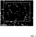
- samples were cut out of the blank and analyzed in cross-sections using scanning electron microscopy and X-ray phase analysis.
- illustration 1 a scanning electron micrograph of the structure of a cross-section through the round sample sintered at 2100°C is shown (the size of the image section is about 115 ⁇ m by 90 ⁇ m, the scale bar corresponds to 20 ⁇ m).
- the image shows a fine-grained, homogeneous structure of the microstructure.
- the high density of the structure with a very low porosity can be seen.
- the directional structure of the structure cannot be seen in this figure, since the plane of the cross-section is perpendicular to the pressing direction and thus also to the orientation of the structure.
- Figure 2 shows the element distribution of the in illustration 1 boxed area of the sample, with Si shown in light and C shown in dark.
- the blank consists essentially only of the elements Si and C.
- the measurement of the grain size revealed a mean diameter of less than 10 ⁇ m for the Si-containing particles, the mean distance between these particles is less than 20 ⁇ m.
- the Si-containing particles are evenly distributed in the structure of the coating source.
- An X-ray diffractogram (XRD) of the sample shows that the dopant silicon is only present in the form of Si carbide, i.e. in a form that has reacted with the carbon, which indicates a chemical reaction that took place during the sintering process Reaction between silicon and carbon indicates.
- XRD X-ray diffractogram
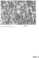
- Figure 4 shows a scanning electron micrograph of the structure of a cross section of a variant of a silicon-doped target with a Si content of 5 mol% and a carbon content of 95 mol%.
- the target was produced in a SPS system at a sintering temperature of 1500° C. (the scale bar corresponds to 10 ⁇ m) analogously to the above variants with the appropriate mixing ratio of C/Si powder.
- a directional structure can be clearly seen in the structure, which can be traced back to the pressing process in the sintering process.
- silicon-doped targets serve to deposit silicon-doped carbon layers, in particular silicon-doped amorphous carbon layers.
- the deposition of the desired layers was demonstrated using the target variant described first.
- the circular blank made of the material CSi 90/10 mol% (diameter 75 mm, thickness 5 mm) sintered at 2100° C. was soldered flat to a back plate made of copper with a diameter of 75 mm and a thickness of 3 mm using indium.
- the target obtained in this way was used in a PVD system in the DC sputtering process to coat a hard metal substrate.
- the target showed stable behavior with regard to the ignition and the stability of the plasma at powers of 200 watts (500 V and 0.4 A), 300 watts (550 V and 0.55 A) and 400 watts (570 V and 0.7A). Silicon and carbon were detected in the layers deposited on the hard metal substrate.
- Example 2 In exemplary embodiment 2, a titanium-doped coating source was produced for the deposition of titanium-doped carbon layers. Approx. 1.5 kg of a mixture of Ti powder and C powder (mean grain size d 50 of approx. 10 ⁇ m) in a mixing ratio of 10/90 mol% were used as the starting material for the circular target with a diameter of 75 mm and a thickness of 5 mm. used, which were ground wet for 4 hours in a pot roller with the addition of 5 l isopropanol and 5 kg grinding balls made of Si nitride.
- the individual production steps are analogous to the process steps in exemplary embodiment 1; the dried powder mixture was sintered at a pressure of 30 MPa and a temperature of 2100° C. in direct current passage and then mechanically processed. XRD analysis performed on cross-sections of the sintered sample showed that titanium is present in the structure only in the form of Ti-carbide through a reaction with the carbon.
- Example 3 In example 3, a target for the physical vapor deposition of carbon layers doped with chromium diboride was produced. The production steps are analogous to those in the method steps in the previous exemplary embodiments. Approx. 1.5 kg of a mixture of chromium diboride powder and C powder (mean particle size d 50 of about 10 ⁇ m) in a mixing ratio of 10/90 mol% were used as the starting material for the circular target with a diameter of 75 mm and a thickness of 5 mm , which were wet ground for 4 hours in a pot roller with the addition of 5 l isopropanol and 5 kg grinding balls made of Si nitride.
- a target for the physical vapor deposition of carbon layers doped with chromium diboride was produced. The production steps are analogous to those in the method steps in the previous exemplary embodiments. Approx. 1.5 kg of a mixture of chromium diboride powder and C powder (mean particle size d 50 of about 10 ⁇ m) in a
- the dried powder mixture was sintered at a pressure of 30 MPa and a temperature of 2100° C. to give a blank with a diameter of 85 mm and a thickness of 8 mm and was then mechanically finished.
- An XRD investigation carried out on cross sections of the sintered sample showed that the dopant is present in a form that has not reacted with the carbon.
Landscapes
- Chemical & Material Sciences (AREA)
- Engineering & Computer Science (AREA)
- Organic Chemistry (AREA)
- Materials Engineering (AREA)
- Mechanical Engineering (AREA)
- Chemical Kinetics & Catalysis (AREA)
- Metallurgy (AREA)
- Physics & Mathematics (AREA)
- Plasma & Fusion (AREA)
- Analytical Chemistry (AREA)
- Manufacturing & Machinery (AREA)
- Inorganic Chemistry (AREA)
- Ceramic Engineering (AREA)
- Structural Engineering (AREA)
- Thermal Sciences (AREA)
- Composite Materials (AREA)
- Physical Vapour Deposition (AREA)
- Carbon And Carbon Compounds (AREA)
Applications Claiming Priority (2)
| Application Number | Priority Date | Filing Date | Title |
|---|---|---|---|
| ATGM70/2015U AT14701U1 (de) | 2015-03-19 | 2015-03-19 | Beschichtungsquelle zur Herstellung dotierter Kohlenstoffschichten |
| PCT/EP2016/000462 WO2016146256A1 (de) | 2015-03-19 | 2016-03-15 | Beschichtungsquelle zur herstellung dotierter kohlenstoffschichten |
Publications (2)
| Publication Number | Publication Date |
|---|---|
| EP3271497A1 EP3271497A1 (de) | 2018-01-24 |
| EP3271497B1 true EP3271497B1 (de) | 2022-09-07 |
Family
ID=55656514
Family Applications (1)
| Application Number | Title | Priority Date | Filing Date |
|---|---|---|---|
| EP16713290.1A Active EP3271497B1 (de) | 2015-03-19 | 2016-03-15 | Beschichtungsquelle und verfahren zur herstellung dotierter kohlenstoffschichten |
Country Status (7)
| Country | Link |
|---|---|
| US (1) | US10781102B2 (enExample) |
| EP (1) | EP3271497B1 (enExample) |
| JP (1) | JP6874930B2 (enExample) |
| KR (1) | KR102622490B1 (enExample) |
| CN (1) | CN107406971B (enExample) |
| AT (1) | AT14701U1 (enExample) |
| WO (1) | WO2016146256A1 (enExample) |
Cited By (2)
| Publication number | Priority date | Publication date | Assignee | Title |
|---|---|---|---|---|
| AT18142U1 (de) * | 2023-02-08 | 2024-03-15 | Plansee Composite Mat Gmbh | Siliziumhaltige übergangsmetallboridverdampfungsquelle |
| DE102023129550A1 (de) | 2023-10-26 | 2025-04-30 | Oerlikon Surface Solutions Ag, Pfäffikon | Schicht mit eingebauten abrasiven Partikeln |
Families Citing this family (11)
| Publication number | Priority date | Publication date | Assignee | Title |
|---|---|---|---|---|
| DE102017124656A1 (de) | 2016-10-25 | 2018-04-26 | Schaeffler Technologies AG & Co. KG | Verfahren zur Herstellung einer Kohlenstoffbeschichtung |
| WO2019108376A1 (en) | 2017-12-01 | 2019-06-06 | Applied Materials, Inc. | Highly etch selective amorphous carbon film |
| CN107937873B (zh) * | 2017-12-22 | 2023-11-14 | 深圳先进技术研究院 | 碳掺杂的过渡金属硼化物涂层、碳-过渡金属硼化物复合涂层、制备方法及应用和切削工具 |
| FR3082527B1 (fr) * | 2018-06-18 | 2020-09-18 | Hydromecanique & Frottement | Piece revetue par un revetement de carbone amorphe non-hydrogene sur une sous-couche comportant du chrome, du carbone et du silicium |
| CN112639174B (zh) * | 2018-08-30 | 2022-09-20 | 赛尼克公司 | 生长半绝缘碳化硅单晶锭的方法和用于生长碳化硅单晶锭的装置 |
| DE102018125631A1 (de) * | 2018-10-16 | 2020-04-16 | Schaeffler Technologies AG & Co. KG | Schichtsystem, Rollelement und Verfahren |
| JP6756886B1 (ja) * | 2019-04-26 | 2020-09-16 | Jx金属株式会社 | ニオブ酸カリウムナトリウムスパッタリングターゲット |
| KR102317512B1 (ko) * | 2019-09-11 | 2021-10-26 | 강원대학교산학협력단 | 리튬 이차 전지용 음극 활물질, 이의 제조방법 및 이를 포함하는 리튬 이차 전지 |
| CN115943477A (zh) * | 2020-08-21 | 2023-04-07 | 朗姆研究公司 | 抗蚀等离子体处理室部件 |
| CN113913735B (zh) * | 2021-09-07 | 2022-06-24 | 广州今泰科技股份有限公司 | 一种钒/钇共掺杂dlc涂层及其制备方法 |
| CN116083847B (zh) * | 2023-01-16 | 2025-03-25 | 厦门金鹭特种合金有限公司 | 一种二硼化钛硬质涂层、涂层刀具及制备方法 |
Family Cites Families (9)
| Publication number | Priority date | Publication date | Assignee | Title |
|---|---|---|---|---|
| GB9910842D0 (en) * | 1999-05-10 | 1999-07-07 | Univ Nanyang | Composite coatings |
| JP2005060765A (ja) | 2003-08-12 | 2005-03-10 | Yamaguchi Prefecture | 硬質皮膜とその製造方法 |
| JP4965579B2 (ja) * | 2006-10-13 | 2012-07-04 | Jx日鉱日石金属株式会社 | Sb−Te基合金焼結体スパッタリングターゲット |
| JP4885305B2 (ja) * | 2008-03-17 | 2012-02-29 | Jx日鉱日石金属株式会社 | 焼結体ターゲット及び焼結体の製造方法 |
| KR20160145839A (ko) * | 2009-05-27 | 2016-12-20 | 제이엑스금속주식회사 | 소결체 타겟 및 소결체의 제조 방법 |
| JP5364202B2 (ja) * | 2010-04-26 | 2013-12-11 | Jx日鉱日石金属株式会社 | Sb−Te基合金焼結体スパッタリングターゲット |
| AT11884U1 (de) * | 2010-05-04 | 2011-06-15 | Plansee Se | Target |
| CN102363215A (zh) * | 2011-11-04 | 2012-02-29 | 中南大学 | 铬铝合金靶材的粉末真空热压烧结制备方法 |
| JP5592022B2 (ja) * | 2012-06-18 | 2014-09-17 | Jx日鉱日石金属株式会社 | 磁気記録膜用スパッタリングターゲット |
-
2015
- 2015-03-19 AT ATGM70/2015U patent/AT14701U1/de not_active IP Right Cessation
-
2016
- 2016-03-15 JP JP2017548472A patent/JP6874930B2/ja active Active
- 2016-03-15 EP EP16713290.1A patent/EP3271497B1/de active Active
- 2016-03-15 WO PCT/EP2016/000462 patent/WO2016146256A1/de not_active Ceased
- 2016-03-15 CN CN201680016783.XA patent/CN107406971B/zh active Active
- 2016-03-15 US US15/556,379 patent/US10781102B2/en active Active
- 2016-03-15 KR KR1020177026239A patent/KR102622490B1/ko active Active
Cited By (2)
| Publication number | Priority date | Publication date | Assignee | Title |
|---|---|---|---|---|
| AT18142U1 (de) * | 2023-02-08 | 2024-03-15 | Plansee Composite Mat Gmbh | Siliziumhaltige übergangsmetallboridverdampfungsquelle |
| DE102023129550A1 (de) | 2023-10-26 | 2025-04-30 | Oerlikon Surface Solutions Ag, Pfäffikon | Schicht mit eingebauten abrasiven Partikeln |
Also Published As
| Publication number | Publication date |
|---|---|
| KR20170129749A (ko) | 2017-11-27 |
| US10781102B2 (en) | 2020-09-22 |
| JP6874930B2 (ja) | 2021-05-19 |
| KR102622490B1 (ko) | 2024-01-08 |
| CN107406971B (zh) | 2020-07-24 |
| US20180105421A1 (en) | 2018-04-19 |
| JP2018511699A (ja) | 2018-04-26 |
| AT14701U1 (de) | 2016-04-15 |
| WO2016146256A1 (de) | 2016-09-22 |
| CN107406971A (zh) | 2017-11-28 |
| EP3271497A1 (de) | 2018-01-24 |
Similar Documents
| Publication | Publication Date | Title |
|---|---|---|
| EP3271497B1 (de) | Beschichtungsquelle und verfahren zur herstellung dotierter kohlenstoffschichten | |
| EP4129958B1 (de) | Verfahren zur herstellung von beschichteten substraten sowie beschichtetes substrat und dessen verwendung | |
| EP0081270B1 (de) | Verfahren zur Herstellung einer thermionischen Kathode und nach diesem Verfahren hergestellte thermionische Kathode | |
| EP2597171B1 (de) | Verfahren zur Herstellung von kubischen Zirkonoxidschichten | |
| EP1360343A1 (de) | Vorrichtung zur keramikartigen beschichtung eines substrates | |
| AT14157U1 (de) | W-Ni-Sputtertarget | |
| EP4251589B1 (de) | Verfahren zur herstellung von beschichteten substraten sowie beschichtetes substrat und dessen verwendung | |
| WO2017152196A1 (de) | Verfahren zur herstellung einer hartstoffschicht auf einem substrat, hartstoffschicht, zerspanwerkzeug sowie beschichtungsquelle | |
| WO2007110149A1 (de) | Gesinterter verschleissbeständiger boridwerkstoff, sinterfähige pulvermischung zur herstellung des werkstoffs, verfahren zur herstellung des werkstoffs und dessen verwendung | |
| EP2326742B1 (de) | Verwendung eines targets für das funkenverdampfen und verfahren zum herstellen eines für diese verwendung geeigneten targets | |
| DE19714432C2 (de) | Trägerkörper mit einer Schutzbeschichtung und Verwendung des beschichteten Trägerkörpers | |
| DE4302407C2 (de) | Verfahren zur Herstellung eines mit einer Schicht aus Diamant beschichteten Elements auf Siliciumnitridbasis | |
| EP0425056A1 (de) | Verfahren zur Abscheidung mikrokristalliner Festkörperpartikel aus der Gasphase mittels Chemical Vapour Deposition (CVD) | |
| DE102024117726A1 (de) | Oxidationsschutzbeschichtung für diboridbasierte Ultrahochtemperaturkeramik, basierend auf elementarem Aluminium und Aluminiumoxidmischungen | |
| EP4430019A1 (de) | Verfahren zur behandlung von porösen substraten sowie behandeltes substrat und dessen verwendung | |
| Han et al. | Influence of nitrogen flow rate on the microstructure and properties of N and Me (Me= Cr, Zr) co-doped diamond-like carbon films | |
| WO2024165268A1 (de) | Siliziumhaltige übergangsmetallboridverdampfungsquelle | |
| DE4221659C2 (de) | Flüchtige, metallorganische Alkoxide und ihre Verwendung zur Herstellung von Mikrokompositen aus Keramik und Metall | |
| JP2016037639A (ja) | 他元素含有蒸発源、dlc膜形成方法及びdlc膜形成装置 | |
| DE3935863C2 (de) | CVD (Chemical Vapour Deposition)-Vorrichtung | |
| EP2020825A2 (de) | Widerstandsheizer und Verfahren zum Herstellen desselben | |
| DE19854385A1 (de) | Verfahren zur Herstellung von Diamantverbundwerkstoffen | |
| EP1065692A2 (de) | Flächige Elektronen-Feldemissionsquelle und Verfahren zu deren Herstellung |
Legal Events
| Date | Code | Title | Description |
|---|---|---|---|
| STAA | Information on the status of an ep patent application or granted ep patent |
Free format text: STATUS: THE INTERNATIONAL PUBLICATION HAS BEEN MADE |
|
| PUAI | Public reference made under article 153(3) epc to a published international application that has entered the european phase |
Free format text: ORIGINAL CODE: 0009012 |
|
| STAA | Information on the status of an ep patent application or granted ep patent |
Free format text: STATUS: REQUEST FOR EXAMINATION WAS MADE |
|
| 17P | Request for examination filed |
Effective date: 20170926 |
|
| AK | Designated contracting states |
Kind code of ref document: A1 Designated state(s): AL AT BE BG CH CY CZ DE DK EE ES FI FR GB GR HR HU IE IS IT LI LT LU LV MC MK MT NL NO PL PT RO RS SE SI SK SM TR |
|
| AX | Request for extension of the european patent |
Extension state: BA ME |
|
| DAV | Request for validation of the european patent (deleted) | ||
| DAX | Request for extension of the european patent (deleted) | ||
| RIC1 | Information provided on ipc code assigned before grant |
Ipc: C23C 14/34 20060101ALI20160929BHEP Ipc: C23C 14/06 20060101ALI20160929BHEP Ipc: H01J 37/34 20060101ALI20160929BHEP Ipc: C01B 31/02 20181130ALI20160929BHEP Ipc: C23C 14/32 20060101ALI20160929BHEP Ipc: C23C 16/26 20060101AFI20160929BHEP |
|
| RIC1 | Information provided on ipc code assigned before grant |
Ipc: C01B 31/02 20060101ALI20160929BHEP Ipc: C23C 14/32 20060101ALI20160929BHEP Ipc: C23C 14/34 20060101ALI20160929BHEP Ipc: C23C 14/06 20060101ALI20160929BHEP Ipc: C23C 16/26 20060101AFI20160929BHEP Ipc: H01J 37/34 20060101ALI20160929BHEP |
|
| STAA | Information on the status of an ep patent application or granted ep patent |
Free format text: STATUS: EXAMINATION IS IN PROGRESS |
|
| 17Q | First examination report despatched |
Effective date: 20200520 |
|
| RIC1 | Information provided on ipc code assigned before grant |
Ipc: H01J 37/32 20060101ALI20220221BHEP Ipc: C01B 32/984 20170101ALI20220221BHEP Ipc: C01B 32/05 20170101ALI20220221BHEP Ipc: H01J 37/34 20060101ALI20220221BHEP Ipc: C23C 14/34 20060101ALI20220221BHEP Ipc: C23C 14/32 20060101ALI20220221BHEP Ipc: C23C 14/06 20060101ALI20220221BHEP Ipc: C23C 16/26 20060101AFI20220221BHEP |
|
| GRAP | Despatch of communication of intention to grant a patent |
Free format text: ORIGINAL CODE: EPIDOSNIGR1 |
|
| STAA | Information on the status of an ep patent application or granted ep patent |
Free format text: STATUS: GRANT OF PATENT IS INTENDED |
|
| INTG | Intention to grant announced |
Effective date: 20220503 |
|
| GRAS | Grant fee paid |
Free format text: ORIGINAL CODE: EPIDOSNIGR3 |
|
| GRAA | (expected) grant |
Free format text: ORIGINAL CODE: 0009210 |
|
| STAA | Information on the status of an ep patent application or granted ep patent |
Free format text: STATUS: THE PATENT HAS BEEN GRANTED |
|
| AK | Designated contracting states |
Kind code of ref document: B1 Designated state(s): AL AT BE BG CH CY CZ DE DK EE ES FI FR GB GR HR HU IE IS IT LI LT LU LV MC MK MT NL NO PL PT RO RS SE SI SK SM TR |
|
| REG | Reference to a national code |
Ref country code: GB Ref legal event code: FG4D Free format text: NOT ENGLISH |
|
| REG | Reference to a national code |
Ref country code: CH Ref legal event code: EP Ref country code: AT Ref legal event code: REF Ref document number: 1517094 Country of ref document: AT Kind code of ref document: T Effective date: 20220915 |
|
| REG | Reference to a national code |
Ref country code: DE Ref legal event code: R096 Ref document number: 502016015248 Country of ref document: DE |
|
| REG | Reference to a national code |
Ref country code: IE Ref legal event code: FG4D Free format text: LANGUAGE OF EP DOCUMENT: GERMAN |
|
| REG | Reference to a national code |
Ref country code: SE Ref legal event code: TRGR |
|
| REG | Reference to a national code |
Ref country code: NL Ref legal event code: FP |
|
| REG | Reference to a national code |
Ref country code: LT Ref legal event code: MG9D |
|
| PG25 | Lapsed in a contracting state [announced via postgrant information from national office to epo] |
Ref country code: RS Free format text: LAPSE BECAUSE OF FAILURE TO SUBMIT A TRANSLATION OF THE DESCRIPTION OR TO PAY THE FEE WITHIN THE PRESCRIBED TIME-LIMIT Effective date: 20220907 Ref country code: NO Free format text: LAPSE BECAUSE OF FAILURE TO SUBMIT A TRANSLATION OF THE DESCRIPTION OR TO PAY THE FEE WITHIN THE PRESCRIBED TIME-LIMIT Effective date: 20221207 Ref country code: LV Free format text: LAPSE BECAUSE OF FAILURE TO SUBMIT A TRANSLATION OF THE DESCRIPTION OR TO PAY THE FEE WITHIN THE PRESCRIBED TIME-LIMIT Effective date: 20220907 Ref country code: LT Free format text: LAPSE BECAUSE OF FAILURE TO SUBMIT A TRANSLATION OF THE DESCRIPTION OR TO PAY THE FEE WITHIN THE PRESCRIBED TIME-LIMIT Effective date: 20220907 Ref country code: FI Free format text: LAPSE BECAUSE OF FAILURE TO SUBMIT A TRANSLATION OF THE DESCRIPTION OR TO PAY THE FEE WITHIN THE PRESCRIBED TIME-LIMIT Effective date: 20220907 Ref country code: ES Free format text: LAPSE BECAUSE OF FAILURE TO SUBMIT A TRANSLATION OF THE DESCRIPTION OR TO PAY THE FEE WITHIN THE PRESCRIBED TIME-LIMIT Effective date: 20220907 |
|
| PG25 | Lapsed in a contracting state [announced via postgrant information from national office to epo] |
Ref country code: HR Free format text: LAPSE BECAUSE OF FAILURE TO SUBMIT A TRANSLATION OF THE DESCRIPTION OR TO PAY THE FEE WITHIN THE PRESCRIBED TIME-LIMIT Effective date: 20220907 Ref country code: GR Free format text: LAPSE BECAUSE OF FAILURE TO SUBMIT A TRANSLATION OF THE DESCRIPTION OR TO PAY THE FEE WITHIN THE PRESCRIBED TIME-LIMIT Effective date: 20221208 |
|
| PG25 | Lapsed in a contracting state [announced via postgrant information from national office to epo] |
Ref country code: SM Free format text: LAPSE BECAUSE OF FAILURE TO SUBMIT A TRANSLATION OF THE DESCRIPTION OR TO PAY THE FEE WITHIN THE PRESCRIBED TIME-LIMIT Effective date: 20220907 Ref country code: RO Free format text: LAPSE BECAUSE OF FAILURE TO SUBMIT A TRANSLATION OF THE DESCRIPTION OR TO PAY THE FEE WITHIN THE PRESCRIBED TIME-LIMIT Effective date: 20220907 Ref country code: PT Free format text: LAPSE BECAUSE OF FAILURE TO SUBMIT A TRANSLATION OF THE DESCRIPTION OR TO PAY THE FEE WITHIN THE PRESCRIBED TIME-LIMIT Effective date: 20230109 |
|
| PG25 | Lapsed in a contracting state [announced via postgrant information from national office to epo] |
Ref country code: SK Free format text: LAPSE BECAUSE OF FAILURE TO SUBMIT A TRANSLATION OF THE DESCRIPTION OR TO PAY THE FEE WITHIN THE PRESCRIBED TIME-LIMIT Effective date: 20220907 Ref country code: PL Free format text: LAPSE BECAUSE OF FAILURE TO SUBMIT A TRANSLATION OF THE DESCRIPTION OR TO PAY THE FEE WITHIN THE PRESCRIBED TIME-LIMIT Effective date: 20220907 Ref country code: IS Free format text: LAPSE BECAUSE OF FAILURE TO SUBMIT A TRANSLATION OF THE DESCRIPTION OR TO PAY THE FEE WITHIN THE PRESCRIBED TIME-LIMIT Effective date: 20230107 Ref country code: EE Free format text: LAPSE BECAUSE OF FAILURE TO SUBMIT A TRANSLATION OF THE DESCRIPTION OR TO PAY THE FEE WITHIN THE PRESCRIBED TIME-LIMIT Effective date: 20220907 |
|
| REG | Reference to a national code |
Ref country code: DE Ref legal event code: R097 Ref document number: 502016015248 Country of ref document: DE |
|
| PG25 | Lapsed in a contracting state [announced via postgrant information from national office to epo] |
Ref country code: AL Free format text: LAPSE BECAUSE OF FAILURE TO SUBMIT A TRANSLATION OF THE DESCRIPTION OR TO PAY THE FEE WITHIN THE PRESCRIBED TIME-LIMIT Effective date: 20220907 |
|
| PLBE | No opposition filed within time limit |
Free format text: ORIGINAL CODE: 0009261 |
|
| STAA | Information on the status of an ep patent application or granted ep patent |
Free format text: STATUS: NO OPPOSITION FILED WITHIN TIME LIMIT |
|
| PG25 | Lapsed in a contracting state [announced via postgrant information from national office to epo] |
Ref country code: DK Free format text: LAPSE BECAUSE OF FAILURE TO SUBMIT A TRANSLATION OF THE DESCRIPTION OR TO PAY THE FEE WITHIN THE PRESCRIBED TIME-LIMIT Effective date: 20220907 |
|
| 26N | No opposition filed |
Effective date: 20230608 |
|
| PG25 | Lapsed in a contracting state [announced via postgrant information from national office to epo] |
Ref country code: SI Free format text: LAPSE BECAUSE OF FAILURE TO SUBMIT A TRANSLATION OF THE DESCRIPTION OR TO PAY THE FEE WITHIN THE PRESCRIBED TIME-LIMIT Effective date: 20220907 |
|
| PG25 | Lapsed in a contracting state [announced via postgrant information from national office to epo] |
Ref country code: MC Free format text: LAPSE BECAUSE OF FAILURE TO SUBMIT A TRANSLATION OF THE DESCRIPTION OR TO PAY THE FEE WITHIN THE PRESCRIBED TIME-LIMIT Effective date: 20220907 |
|
| REG | Reference to a national code |
Ref country code: BE Ref legal event code: MM Effective date: 20230331 |
|
| PG25 | Lapsed in a contracting state [announced via postgrant information from national office to epo] |
Ref country code: LU Free format text: LAPSE BECAUSE OF NON-PAYMENT OF DUE FEES Effective date: 20230315 |
|
| REG | Reference to a national code |
Ref country code: IE Ref legal event code: MM4A |
|
| PG25 | Lapsed in a contracting state [announced via postgrant information from national office to epo] |
Ref country code: IE Free format text: LAPSE BECAUSE OF NON-PAYMENT OF DUE FEES Effective date: 20230315 |
|
| PG25 | Lapsed in a contracting state [announced via postgrant information from national office to epo] |
Ref country code: BE Free format text: LAPSE BECAUSE OF NON-PAYMENT OF DUE FEES Effective date: 20230331 |
|
| REG | Reference to a national code |
Ref country code: AT Ref legal event code: MM01 Ref document number: 1517094 Country of ref document: AT Kind code of ref document: T Effective date: 20230315 |
|
| PG25 | Lapsed in a contracting state [announced via postgrant information from national office to epo] |
Ref country code: IT Free format text: LAPSE BECAUSE OF FAILURE TO SUBMIT A TRANSLATION OF THE DESCRIPTION OR TO PAY THE FEE WITHIN THE PRESCRIBED TIME-LIMIT Effective date: 20220907 |
|
| PG25 | Lapsed in a contracting state [announced via postgrant information from national office to epo] |
Ref country code: AT Free format text: LAPSE BECAUSE OF NON-PAYMENT OF DUE FEES Effective date: 20230315 |
|
| PG25 | Lapsed in a contracting state [announced via postgrant information from national office to epo] |
Ref country code: AT Free format text: LAPSE BECAUSE OF NON-PAYMENT OF DUE FEES Effective date: 20230315 |
|
| PG25 | Lapsed in a contracting state [announced via postgrant information from national office to epo] |
Ref country code: BG Free format text: LAPSE BECAUSE OF FAILURE TO SUBMIT A TRANSLATION OF THE DESCRIPTION OR TO PAY THE FEE WITHIN THE PRESCRIBED TIME-LIMIT Effective date: 20220907 |
|
| PG25 | Lapsed in a contracting state [announced via postgrant information from national office to epo] |
Ref country code: BG Free format text: LAPSE BECAUSE OF FAILURE TO SUBMIT A TRANSLATION OF THE DESCRIPTION OR TO PAY THE FEE WITHIN THE PRESCRIBED TIME-LIMIT Effective date: 20220907 |
|
| PGFP | Annual fee paid to national office [announced via postgrant information from national office to epo] |
Ref country code: CH Payment date: 20250401 Year of fee payment: 10 |
|
| PG25 | Lapsed in a contracting state [announced via postgrant information from national office to epo] |
Ref country code: CY Free format text: LAPSE BECAUSE OF FAILURE TO SUBMIT A TRANSLATION OF THE DESCRIPTION OR TO PAY THE FEE WITHIN THE PRESCRIBED TIME-LIMIT; INVALID AB INITIO Effective date: 20160315 |
|
| PG25 | Lapsed in a contracting state [announced via postgrant information from national office to epo] |
Ref country code: HU Free format text: LAPSE BECAUSE OF FAILURE TO SUBMIT A TRANSLATION OF THE DESCRIPTION OR TO PAY THE FEE WITHIN THE PRESCRIBED TIME-LIMIT; INVALID AB INITIO Effective date: 20160315 |
|
| PG25 | Lapsed in a contracting state [announced via postgrant information from national office to epo] |
Ref country code: TR Free format text: LAPSE BECAUSE OF FAILURE TO SUBMIT A TRANSLATION OF THE DESCRIPTION OR TO PAY THE FEE WITHIN THE PRESCRIBED TIME-LIMIT Effective date: 20220907 |
|
| REG | Reference to a national code |
Ref country code: CH Ref legal event code: U11 Free format text: ST27 STATUS EVENT CODE: U-0-0-U10-U11 (AS PROVIDED BY THE NATIONAL OFFICE) Effective date: 20260401 |
|
| PGFP | Annual fee paid to national office [announced via postgrant information from national office to epo] |
Ref country code: SE Payment date: 20260319 Year of fee payment: 11 |
|
| PGFP | Annual fee paid to national office [announced via postgrant information from national office to epo] |
Ref country code: GB Payment date: 20260324 Year of fee payment: 11 |
|
| PGFP | Annual fee paid to national office [announced via postgrant information from national office to epo] |
Ref country code: DE Payment date: 20260319 Year of fee payment: 11 |
|
| PGFP | Annual fee paid to national office [announced via postgrant information from national office to epo] |
Ref country code: NL Payment date: 20260319 Year of fee payment: 11 |
|
| PGFP | Annual fee paid to national office [announced via postgrant information from national office to epo] |
Ref country code: FR Payment date: 20260320 Year of fee payment: 11 |
|
| PGFP | Annual fee paid to national office [announced via postgrant information from national office to epo] |
Ref country code: CZ Payment date: 20260310 Year of fee payment: 11 |