EP3271497B1 - Beschichtungsquelle und verfahren zur herstellung dotierter kohlenstoffschichten - Google Patents
Beschichtungsquelle und verfahren zur herstellung dotierter kohlenstoffschichten Download PDFInfo
- Publication number
- EP3271497B1 EP3271497B1 EP16713290.1A EP16713290A EP3271497B1 EP 3271497 B1 EP3271497 B1 EP 3271497B1 EP 16713290 A EP16713290 A EP 16713290A EP 3271497 B1 EP3271497 B1 EP 3271497B1
- Authority
- EP
- European Patent Office
- Prior art keywords
- dopant
- coating source
- carbon
- semimetal
- metal
- Prior art date
- Legal status (The legal status is an assumption and is not a legal conclusion. Google has not performed a legal analysis and makes no representation as to the accuracy of the status listed.)
- Active
Links
Images

Classifications
-
- B—PERFORMING OPERATIONS; TRANSPORTING
- B22—CASTING; POWDER METALLURGY
- B22F—WORKING METALLIC POWDER; MANUFACTURE OF ARTICLES FROM METALLIC POWDER; MAKING METALLIC POWDER; APPARATUS OR DEVICES SPECIALLY ADAPTED FOR METALLIC POWDER
- B22F3/00—Manufacture of workpieces or articles from metallic powder characterised by the manner of compacting or sintering; Apparatus specially adapted therefor ; Presses and furnaces
- B22F3/10—Sintering only
-
- C—CHEMISTRY; METALLURGY
- C23—COATING METALLIC MATERIAL; COATING MATERIAL WITH METALLIC MATERIAL; CHEMICAL SURFACE TREATMENT; DIFFUSION TREATMENT OF METALLIC MATERIAL; COATING BY VACUUM EVAPORATION, BY SPUTTERING, BY ION IMPLANTATION OR BY CHEMICAL VAPOUR DEPOSITION, IN GENERAL; INHIBITING CORROSION OF METALLIC MATERIAL OR INCRUSTATION IN GENERAL
- C23C—COATING METALLIC MATERIAL; COATING MATERIAL WITH METALLIC MATERIAL; SURFACE TREATMENT OF METALLIC MATERIAL BY DIFFUSION INTO THE SURFACE, BY CHEMICAL CONVERSION OR SUBSTITUTION; COATING BY VACUUM EVAPORATION, BY SPUTTERING, BY ION IMPLANTATION OR BY CHEMICAL VAPOUR DEPOSITION, IN GENERAL
- C23C14/00—Coating by vacuum evaporation, by sputtering or by ion implantation of the coating forming material
- C23C14/06—Coating by vacuum evaporation, by sputtering or by ion implantation of the coating forming material characterised by the coating material
- C23C14/0605—Carbon
-
- C—CHEMISTRY; METALLURGY
- C04—CEMENTS; CONCRETE; ARTIFICIAL STONE; CERAMICS; REFRACTORIES
- C04B—LIME, MAGNESIA; SLAG; CEMENTS; COMPOSITIONS THEREOF, e.g. MORTARS, CONCRETE OR LIKE BUILDING MATERIALS; ARTIFICIAL STONE; CERAMICS; REFRACTORIES; TREATMENT OF NATURAL STONE
- C04B35/00—Shaped ceramic products characterised by their composition; Ceramics compositions; Processing powders of inorganic compounds preparatory to the manufacturing of ceramic products
- C04B35/515—Shaped ceramic products characterised by their composition; Ceramics compositions; Processing powders of inorganic compounds preparatory to the manufacturing of ceramic products based on non-oxide ceramics
- C04B35/52—Shaped ceramic products characterised by their composition; Ceramics compositions; Processing powders of inorganic compounds preparatory to the manufacturing of ceramic products based on non-oxide ceramics based on carbon, e.g. graphite
- C04B35/528—Shaped ceramic products characterised by their composition; Ceramics compositions; Processing powders of inorganic compounds preparatory to the manufacturing of ceramic products based on non-oxide ceramics based on carbon, e.g. graphite obtained from carbonaceous particles with or without other non-organic components
-
- B—PERFORMING OPERATIONS; TRANSPORTING
- B22—CASTING; POWDER METALLURGY
- B22F—WORKING METALLIC POWDER; MANUFACTURE OF ARTICLES FROM METALLIC POWDER; MAKING METALLIC POWDER; APPARATUS OR DEVICES SPECIALLY ADAPTED FOR METALLIC POWDER
- B22F3/00—Manufacture of workpieces or articles from metallic powder characterised by the manner of compacting or sintering; Apparatus specially adapted therefor ; Presses and furnaces
- B22F3/12—Both compacting and sintering
- B22F3/14—Both compacting and sintering simultaneously
-
- B—PERFORMING OPERATIONS; TRANSPORTING
- B22—CASTING; POWDER METALLURGY
- B22F—WORKING METALLIC POWDER; MANUFACTURE OF ARTICLES FROM METALLIC POWDER; MAKING METALLIC POWDER; APPARATUS OR DEVICES SPECIALLY ADAPTED FOR METALLIC POWDER
- B22F7/00—Manufacture of composite layers, workpieces, or articles, comprising metallic powder, by sintering the powder, with or without compacting wherein at least one part is obtained by sintering or compression
- B22F7/008—Manufacture of composite layers, workpieces, or articles, comprising metallic powder, by sintering the powder, with or without compacting wherein at least one part is obtained by sintering or compression characterised by the composition
-
- C—CHEMISTRY; METALLURGY
- C01—INORGANIC CHEMISTRY
- C01B—NON-METALLIC ELEMENTS; COMPOUNDS THEREOF; METALLOIDS OR COMPOUNDS THEREOF NOT COVERED BY SUBCLASS C01C
- C01B32/00—Carbon; Compounds thereof
- C01B32/90—Carbides
- C01B32/914—Carbides of single elements
- C01B32/921—Titanium carbide
-
- C—CHEMISTRY; METALLURGY
- C01—INORGANIC CHEMISTRY
- C01B—NON-METALLIC ELEMENTS; COMPOUNDS THEREOF; METALLOIDS OR COMPOUNDS THEREOF NOT COVERED BY SUBCLASS C01C
- C01B32/00—Carbon; Compounds thereof
- C01B32/90—Carbides
- C01B32/914—Carbides of single elements
- C01B32/956—Silicon carbide
-
- C—CHEMISTRY; METALLURGY
- C01—INORGANIC CHEMISTRY
- C01B—NON-METALLIC ELEMENTS; COMPOUNDS THEREOF; METALLOIDS OR COMPOUNDS THEREOF NOT COVERED BY SUBCLASS C01C
- C01B32/00—Carbon; Compounds thereof
- C01B32/90—Carbides
- C01B32/914—Carbides of single elements
- C01B32/956—Silicon carbide
- C01B32/963—Preparation from compounds containing silicon
- C01B32/984—Preparation from elemental silicon
-
- C—CHEMISTRY; METALLURGY
- C04—CEMENTS; CONCRETE; ARTIFICIAL STONE; CERAMICS; REFRACTORIES
- C04B—LIME, MAGNESIA; SLAG; CEMENTS; COMPOSITIONS THEREOF, e.g. MORTARS, CONCRETE OR LIKE BUILDING MATERIALS; ARTIFICIAL STONE; CERAMICS; REFRACTORIES; TREATMENT OF NATURAL STONE
- C04B35/00—Shaped ceramic products characterised by their composition; Ceramics compositions; Processing powders of inorganic compounds preparatory to the manufacturing of ceramic products
- C04B35/622—Forming processes; Processing powders of inorganic compounds preparatory to the manufacturing of ceramic products
- C04B35/64—Burning or sintering processes
-
- C—CHEMISTRY; METALLURGY
- C04—CEMENTS; CONCRETE; ARTIFICIAL STONE; CERAMICS; REFRACTORIES
- C04B—LIME, MAGNESIA; SLAG; CEMENTS; COMPOSITIONS THEREOF, e.g. MORTARS, CONCRETE OR LIKE BUILDING MATERIALS; ARTIFICIAL STONE; CERAMICS; REFRACTORIES; TREATMENT OF NATURAL STONE
- C04B41/00—After-treatment of mortars, concrete, artificial stone or ceramics; Treatment of natural stone
- C04B41/80—After-treatment of mortars, concrete, artificial stone or ceramics; Treatment of natural stone of only ceramics
-
- C—CHEMISTRY; METALLURGY
- C23—COATING METALLIC MATERIAL; COATING MATERIAL WITH METALLIC MATERIAL; CHEMICAL SURFACE TREATMENT; DIFFUSION TREATMENT OF METALLIC MATERIAL; COATING BY VACUUM EVAPORATION, BY SPUTTERING, BY ION IMPLANTATION OR BY CHEMICAL VAPOUR DEPOSITION, IN GENERAL; INHIBITING CORROSION OF METALLIC MATERIAL OR INCRUSTATION IN GENERAL
- C23C—COATING METALLIC MATERIAL; COATING MATERIAL WITH METALLIC MATERIAL; SURFACE TREATMENT OF METALLIC MATERIAL BY DIFFUSION INTO THE SURFACE, BY CHEMICAL CONVERSION OR SUBSTITUTION; COATING BY VACUUM EVAPORATION, BY SPUTTERING, BY ION IMPLANTATION OR BY CHEMICAL VAPOUR DEPOSITION, IN GENERAL
- C23C14/00—Coating by vacuum evaporation, by sputtering or by ion implantation of the coating forming material
- C23C14/06—Coating by vacuum evaporation, by sputtering or by ion implantation of the coating forming material characterised by the coating material
- C23C14/0682—Silicides
-
- C—CHEMISTRY; METALLURGY
- C23—COATING METALLIC MATERIAL; COATING MATERIAL WITH METALLIC MATERIAL; CHEMICAL SURFACE TREATMENT; DIFFUSION TREATMENT OF METALLIC MATERIAL; COATING BY VACUUM EVAPORATION, BY SPUTTERING, BY ION IMPLANTATION OR BY CHEMICAL VAPOUR DEPOSITION, IN GENERAL; INHIBITING CORROSION OF METALLIC MATERIAL OR INCRUSTATION IN GENERAL
- C23C—COATING METALLIC MATERIAL; COATING MATERIAL WITH METALLIC MATERIAL; SURFACE TREATMENT OF METALLIC MATERIAL BY DIFFUSION INTO THE SURFACE, BY CHEMICAL CONVERSION OR SUBSTITUTION; COATING BY VACUUM EVAPORATION, BY SPUTTERING, BY ION IMPLANTATION OR BY CHEMICAL VAPOUR DEPOSITION, IN GENERAL
- C23C14/00—Coating by vacuum evaporation, by sputtering or by ion implantation of the coating forming material
- C23C14/22—Coating by vacuum evaporation, by sputtering or by ion implantation of the coating forming material characterised by the process of coating
- C23C14/24—Vacuum evaporation
- C23C14/32—Vacuum evaporation by explosion; by evaporation and subsequent ionisation of the vapours, e.g. ion-plating
- C23C14/325—Electric arc evaporation
-
- C—CHEMISTRY; METALLURGY
- C23—COATING METALLIC MATERIAL; COATING MATERIAL WITH METALLIC MATERIAL; CHEMICAL SURFACE TREATMENT; DIFFUSION TREATMENT OF METALLIC MATERIAL; COATING BY VACUUM EVAPORATION, BY SPUTTERING, BY ION IMPLANTATION OR BY CHEMICAL VAPOUR DEPOSITION, IN GENERAL; INHIBITING CORROSION OF METALLIC MATERIAL OR INCRUSTATION IN GENERAL
- C23C—COATING METALLIC MATERIAL; COATING MATERIAL WITH METALLIC MATERIAL; SURFACE TREATMENT OF METALLIC MATERIAL BY DIFFUSION INTO THE SURFACE, BY CHEMICAL CONVERSION OR SUBSTITUTION; COATING BY VACUUM EVAPORATION, BY SPUTTERING, BY ION IMPLANTATION OR BY CHEMICAL VAPOUR DEPOSITION, IN GENERAL
- C23C14/00—Coating by vacuum evaporation, by sputtering or by ion implantation of the coating forming material
- C23C14/22—Coating by vacuum evaporation, by sputtering or by ion implantation of the coating forming material characterised by the process of coating
- C23C14/34—Sputtering
- C23C14/3407—Cathode assembly for sputtering apparatus, e.g. Target
- C23C14/3414—Metallurgical or chemical aspects of target preparation, e.g. casting, powder metallurgy
-
- C—CHEMISTRY; METALLURGY
- C23—COATING METALLIC MATERIAL; COATING MATERIAL WITH METALLIC MATERIAL; CHEMICAL SURFACE TREATMENT; DIFFUSION TREATMENT OF METALLIC MATERIAL; COATING BY VACUUM EVAPORATION, BY SPUTTERING, BY ION IMPLANTATION OR BY CHEMICAL VAPOUR DEPOSITION, IN GENERAL; INHIBITING CORROSION OF METALLIC MATERIAL OR INCRUSTATION IN GENERAL
- C23C—COATING METALLIC MATERIAL; COATING MATERIAL WITH METALLIC MATERIAL; SURFACE TREATMENT OF METALLIC MATERIAL BY DIFFUSION INTO THE SURFACE, BY CHEMICAL CONVERSION OR SUBSTITUTION; COATING BY VACUUM EVAPORATION, BY SPUTTERING, BY ION IMPLANTATION OR BY CHEMICAL VAPOUR DEPOSITION, IN GENERAL
- C23C14/00—Coating by vacuum evaporation, by sputtering or by ion implantation of the coating forming material
- C23C14/58—After-treatment
- C23C14/5806—Thermal treatment
-
- H—ELECTRICITY
- H01—ELECTRIC ELEMENTS
- H01J—ELECTRIC DISCHARGE TUBES OR DISCHARGE LAMPS
- H01J37/00—Discharge tubes with provision for introducing objects or material to be exposed to the discharge, e.g. for the purpose of examination or processing thereof
- H01J37/32—Gas-filled discharge tubes
- H01J37/32431—Constructional details of the reactor
- H01J37/32532—Electrodes
- H01J37/32614—Consumable cathodes for arc discharge
-
- H—ELECTRICITY
- H01—ELECTRIC ELEMENTS
- H01J—ELECTRIC DISCHARGE TUBES OR DISCHARGE LAMPS
- H01J37/00—Discharge tubes with provision for introducing objects or material to be exposed to the discharge, e.g. for the purpose of examination or processing thereof
- H01J37/32—Gas-filled discharge tubes
- H01J37/34—Gas-filled discharge tubes operating with cathodic sputtering
- H01J37/3411—Constructional aspects of the reactor
- H01J37/3414—Targets
- H01J37/3426—Material
-
- H—ELECTRICITY
- H01—ELECTRIC ELEMENTS
- H01J—ELECTRIC DISCHARGE TUBES OR DISCHARGE LAMPS
- H01J37/00—Discharge tubes with provision for introducing objects or material to be exposed to the discharge, e.g. for the purpose of examination or processing thereof
- H01J37/32—Gas-filled discharge tubes
- H01J37/34—Gas-filled discharge tubes operating with cathodic sputtering
- H01J37/3488—Constructional details of particle beam apparatus not otherwise provided for, e.g. arrangement, mounting, housing, environment; special provisions for cleaning or maintenance of the apparatus
- H01J37/3491—Manufacturing of targets
-
- B—PERFORMING OPERATIONS; TRANSPORTING
- B22—CASTING; POWDER METALLURGY
- B22F—WORKING METALLIC POWDER; MANUFACTURE OF ARTICLES FROM METALLIC POWDER; MAKING METALLIC POWDER; APPARATUS OR DEVICES SPECIALLY ADAPTED FOR METALLIC POWDER
- B22F2302/00—Metal Compound, non-Metallic compound or non-metal composition of the powder or its coating
- B22F2302/10—Carbide
-
- B—PERFORMING OPERATIONS; TRANSPORTING
- B22—CASTING; POWDER METALLURGY
- B22F—WORKING METALLIC POWDER; MANUFACTURE OF ARTICLES FROM METALLIC POWDER; MAKING METALLIC POWDER; APPARATUS OR DEVICES SPECIALLY ADAPTED FOR METALLIC POWDER
- B22F2302/00—Metal Compound, non-Metallic compound or non-metal composition of the powder or its coating
- B22F2302/40—Carbon, graphite
-
- B—PERFORMING OPERATIONS; TRANSPORTING
- B22—CASTING; POWDER METALLURGY
- B22F—WORKING METALLIC POWDER; MANUFACTURE OF ARTICLES FROM METALLIC POWDER; MAKING METALLIC POWDER; APPARATUS OR DEVICES SPECIALLY ADAPTED FOR METALLIC POWDER
- B22F2998/00—Supplementary information concerning processes or compositions relating to powder metallurgy
- B22F2998/10—Processes characterised by the sequence of their steps
-
- C—CHEMISTRY; METALLURGY
- C01—INORGANIC CHEMISTRY
- C01B—NON-METALLIC ELEMENTS; COMPOUNDS THEREOF; METALLOIDS OR COMPOUNDS THEREOF NOT COVERED BY SUBCLASS C01C
- C01B32/00—Carbon; Compounds thereof
- C01B32/05—Preparation or purification of carbon not covered by groups C01B32/15, C01B32/20, C01B32/25, C01B32/30
-
- C—CHEMISTRY; METALLURGY
- C01—INORGANIC CHEMISTRY
- C01P—INDEXING SCHEME RELATING TO STRUCTURAL AND PHYSICAL ASPECTS OF SOLID INORGANIC COMPOUNDS
- C01P2004/00—Particle morphology
- C01P2004/60—Particles characterised by their size
- C01P2004/61—Micrometer sized, i.e. from 1-100 micrometer
-
- C—CHEMISTRY; METALLURGY
- C04—CEMENTS; CONCRETE; ARTIFICIAL STONE; CERAMICS; REFRACTORIES
- C04B—LIME, MAGNESIA; SLAG; CEMENTS; COMPOSITIONS THEREOF, e.g. MORTARS, CONCRETE OR LIKE BUILDING MATERIALS; ARTIFICIAL STONE; CERAMICS; REFRACTORIES; TREATMENT OF NATURAL STONE
- C04B2235/00—Aspects relating to ceramic starting mixtures or sintered ceramic products
- C04B2235/02—Composition of constituents of the starting material or of secondary phases of the final product
- C04B2235/30—Constituents and secondary phases not being of a fibrous nature
- C04B2235/40—Metallic constituents or additives not added as binding phase
- C04B2235/404—Refractory metals
-
- C—CHEMISTRY; METALLURGY
- C04—CEMENTS; CONCRETE; ARTIFICIAL STONE; CERAMICS; REFRACTORIES
- C04B—LIME, MAGNESIA; SLAG; CEMENTS; COMPOSITIONS THEREOF, e.g. MORTARS, CONCRETE OR LIKE BUILDING MATERIALS; ARTIFICIAL STONE; CERAMICS; REFRACTORIES; TREATMENT OF NATURAL STONE
- C04B2235/00—Aspects relating to ceramic starting mixtures or sintered ceramic products
- C04B2235/65—Aspects relating to heat treatments of ceramic bodies such as green ceramics or pre-sintered ceramics, e.g. burning, sintering or melting processes
- C04B2235/66—Specific sintering techniques, e.g. centrifugal sintering
- C04B2235/666—Applying a current during sintering, e.g. plasma sintering [SPS], electrical resistance heating or pulse electric current sintering [PECS]
-
- C—CHEMISTRY; METALLURGY
- C04—CEMENTS; CONCRETE; ARTIFICIAL STONE; CERAMICS; REFRACTORIES
- C04B—LIME, MAGNESIA; SLAG; CEMENTS; COMPOSITIONS THEREOF, e.g. MORTARS, CONCRETE OR LIKE BUILDING MATERIALS; ARTIFICIAL STONE; CERAMICS; REFRACTORIES; TREATMENT OF NATURAL STONE
- C04B2235/00—Aspects relating to ceramic starting mixtures or sintered ceramic products
- C04B2235/70—Aspects relating to sintered or melt-casted ceramic products
- C04B2235/74—Physical characteristics
- C04B2235/78—Grain sizes and shapes, product microstructures, e.g. acicular grains, equiaxed grains, platelet-structures
- C04B2235/785—Submicron sized grains, i.e. from 0,1 to 1 micron
-
- C—CHEMISTRY; METALLURGY
- C04—CEMENTS; CONCRETE; ARTIFICIAL STONE; CERAMICS; REFRACTORIES
- C04B—LIME, MAGNESIA; SLAG; CEMENTS; COMPOSITIONS THEREOF, e.g. MORTARS, CONCRETE OR LIKE BUILDING MATERIALS; ARTIFICIAL STONE; CERAMICS; REFRACTORIES; TREATMENT OF NATURAL STONE
- C04B2235/00—Aspects relating to ceramic starting mixtures or sintered ceramic products
- C04B2235/70—Aspects relating to sintered or melt-casted ceramic products
- C04B2235/74—Physical characteristics
- C04B2235/78—Grain sizes and shapes, product microstructures, e.g. acicular grains, equiaxed grains, platelet-structures
- C04B2235/786—Micrometer sized grains, i.e. from 1 to 100 micron
-
- C—CHEMISTRY; METALLURGY
- C23—COATING METALLIC MATERIAL; COATING MATERIAL WITH METALLIC MATERIAL; CHEMICAL SURFACE TREATMENT; DIFFUSION TREATMENT OF METALLIC MATERIAL; COATING BY VACUUM EVAPORATION, BY SPUTTERING, BY ION IMPLANTATION OR BY CHEMICAL VAPOUR DEPOSITION, IN GENERAL; INHIBITING CORROSION OF METALLIC MATERIAL OR INCRUSTATION IN GENERAL
- C23C—COATING METALLIC MATERIAL; COATING MATERIAL WITH METALLIC MATERIAL; SURFACE TREATMENT OF METALLIC MATERIAL BY DIFFUSION INTO THE SURFACE, BY CHEMICAL CONVERSION OR SUBSTITUTION; COATING BY VACUUM EVAPORATION, BY SPUTTERING, BY ION IMPLANTATION OR BY CHEMICAL VAPOUR DEPOSITION, IN GENERAL
- C23C14/00—Coating by vacuum evaporation, by sputtering or by ion implantation of the coating forming material
- C23C14/06—Coating by vacuum evaporation, by sputtering or by ion implantation of the coating forming material characterised by the coating material
- C23C14/0641—Nitrides
-
- C—CHEMISTRY; METALLURGY
- C23—COATING METALLIC MATERIAL; COATING MATERIAL WITH METALLIC MATERIAL; CHEMICAL SURFACE TREATMENT; DIFFUSION TREATMENT OF METALLIC MATERIAL; COATING BY VACUUM EVAPORATION, BY SPUTTERING, BY ION IMPLANTATION OR BY CHEMICAL VAPOUR DEPOSITION, IN GENERAL; INHIBITING CORROSION OF METALLIC MATERIAL OR INCRUSTATION IN GENERAL
- C23C—COATING METALLIC MATERIAL; COATING MATERIAL WITH METALLIC MATERIAL; SURFACE TREATMENT OF METALLIC MATERIAL BY DIFFUSION INTO THE SURFACE, BY CHEMICAL CONVERSION OR SUBSTITUTION; COATING BY VACUUM EVAPORATION, BY SPUTTERING, BY ION IMPLANTATION OR BY CHEMICAL VAPOUR DEPOSITION, IN GENERAL
- C23C14/00—Coating by vacuum evaporation, by sputtering or by ion implantation of the coating forming material
- C23C14/06—Coating by vacuum evaporation, by sputtering or by ion implantation of the coating forming material characterised by the coating material
- C23C14/067—Borides
-
- C—CHEMISTRY; METALLURGY
- C23—COATING METALLIC MATERIAL; COATING MATERIAL WITH METALLIC MATERIAL; CHEMICAL SURFACE TREATMENT; DIFFUSION TREATMENT OF METALLIC MATERIAL; COATING BY VACUUM EVAPORATION, BY SPUTTERING, BY ION IMPLANTATION OR BY CHEMICAL VAPOUR DEPOSITION, IN GENERAL; INHIBITING CORROSION OF METALLIC MATERIAL OR INCRUSTATION IN GENERAL
- C23C—COATING METALLIC MATERIAL; COATING MATERIAL WITH METALLIC MATERIAL; SURFACE TREATMENT OF METALLIC MATERIAL BY DIFFUSION INTO THE SURFACE, BY CHEMICAL CONVERSION OR SUBSTITUTION; COATING BY VACUUM EVAPORATION, BY SPUTTERING, BY ION IMPLANTATION OR BY CHEMICAL VAPOUR DEPOSITION, IN GENERAL
- C23C14/00—Coating by vacuum evaporation, by sputtering or by ion implantation of the coating forming material
- C23C14/06—Coating by vacuum evaporation, by sputtering or by ion implantation of the coating forming material characterised by the coating material
- C23C14/08—Oxides
Definitions
- the present invention relates to a coating source for the physical vapor deposition of doped carbon layers, in particular of doped amorphous carbon layers, and a manufacturing method for such a coating source.
- Amorphous carbon layers are carbon-containing layers that , in contrast to graphite layers (have a crystalline structure and sp 2 hybridized carbon atoms) and diamond layers (have a crystalline structure and sp 3 hybridized carbon atoms), structurally consist of one amorphous network of sp 2 and sp 3 hybridized carbon atoms.
- Amorphous carbon layers can be hydrogen-free or hydrogen-containing and contain dopings of other elements.
- the various types of amorphous carbon layers are classified in VDI 2840 (Association of German Engineers, carbon layers, basics, layer types and properties). Due to both graphite and diamond-like structures, many of the properties of amorphous carbon layers lie between those of graphite and diamond.
- Amorphous carbon layers are characterized by a hardness similar to diamond (hardness up to 90 GPa) and at the same time have high wear resistance, a low coefficient of friction and good layer adhesion. These layers are therefore increasingly being used, among other things, for tribological applications, for example as friction-reducing and wear-resistant coatings for automobile components. In addition, amorphous carbon layers have excellent biological compatibility.
- a limited thermal stability is disadvantageous because the poor oxidation resistance of amorphous carbon layers means that the temperature at which they can be used is limited to around 350°C.
- Amorphous carbon layers are usually deposited as thin layers with layer thicknesses of a few microns, usually over chemical or physical vapor deposition.
- CVD chemical vapor deposition
- engl Plasma plasma-assisted chemical vapor deposition
- PVD physical vapor deposition
- argon or carbon-containing gases ionized by a plasma is accelerated in a chamber onto a target formed from the coating material, as a result of which particles of the coating material are knocked out, pass into the gas phase and out of the gas phase on the surface to be coated substrate are deposited.
- An additional magnetic field is applied near the active surface of the target to increase the sputtering rate and thus speed up the coating process.
- the coating material provided as the cathode is locally melted and vaporized by an arc moving across the cathode.
- the partially ionized coating material vapor spreads out from the cathode, optionally supported by an additional applied electrical voltage, and condenses on the substrate surface to be coated.
- PVD processes compared to CVD processes is that the thermal load on the substrate is generally lower in PVD processes than in CVD processes and therefore also with PVD processes temperature-sensitive materials can be coated.
- chemical reactions with the working gas can also occur in PVD processes.
- amorphous carbon layers are diverse and can be adjusted over a wide range by varying the hydrogen content and suitable doping.
- metals such as tungsten, titanium or vanadium and non-carbide-forming metals such as gold, copper or silver
- non-metallic elements e.g. silicon, oxygen, nitrogen, fluorine and boron
- doping material dopant
- the thermal stability, the wear resistance and the coefficient of friction of the carbon layers can be influenced by doping with silicon, titanium, chromium, tungsten or molybdenum, the proportion of the dopant usually being less than 25 mol% (mole percent).
- CVD methods have the disadvantage compared to PVD methods that many important dopants such as molybdenum or tungsten are not present in a suitable liquid or gaseous compound. This is one of the disadvantages compared to the PVD process.
- the quality of the layers produced is not entirely satisfactory for industrial applications, since inhomogeneities nevertheless occur in the coating layer, which can be attributed to the composition of the vaporized coating material that varies over time.
- the erosion of the cathode is inhomogeneous and the service life of the cathode is reduced.
- Targets are also known in which a porous base body made of graphite is infiltrated with a melt of a dopant or via a gas phase that contains the dopant.
- the graphite base body In order to be able to be infiltrated, the graphite base body must have an open-pored structure and for this reason the dopant content of infiltrated graphite targets cannot be selected below a specific threshold value. If the infiltration is terminated prematurely in order to set low levels of dopants, a high proportion of porosity remains.
- Another disadvantage is that inhomogeneities occur during the material removal during the coating process due to the coherent network of the dopant in the target.
- the object of the present invention is to provide a coating source for physical vapor phase deposition for the production of doped carbon layers, in particular doped amorphous carbon layers, in which the aforementioned disadvantages occurring when using a plurality of coating sources are avoided or reduced.
- the coating source should, in particular, enable the dopant to be distributed as homogeneously as possible in the deposited carbon layer. In addition, it should not tend towards a locally increased evaporation rate in the event of arc evaporation.
- Another object of the present invention is to provide a manufacturing method for such a coating source.
- the doped coating source according to the invention is produced by sintering a powder mixture of carbon-containing powder (or a carbon-containing powder mixture) and dopant-containing powder (or a dopant-containing powder mixture). It has carbon as matrix material with a mole fraction of at least 75 mol% and at least one dopant with a mole fraction of between 1 mol% and 25 mol%, preferably between 1 mol% and 20 mol%, particularly preferably between 2 mol% and 10 mol% up.
- the mole fraction of the at least one dopant can be less than 5 mol %.
- the usual production-related impurities such as sulfur can be present in the coating source, with the amount of impurities typically being less than 1000 ppm.
- the dopant is used for the targeted modification of the carbon layer deposited using the coating source.
- the dopant can be a metal or a semimetal.
- the dopant can also be an oxidic, nitridic, boric or silicide compound of a metal or a semimetal.
- the metals titanium, vanadium, chromium, zirconium, niobium, molybdenum, hafnium, tantalum, tungsten and the semimetal silicon can be used as dopants.
- Oxides, nitrides, borides or silicides of the metals titanium, vanadium, chromium, zirconium, niobium, molybdenum, hafnium, tantalum, tungsten or oxides, nitrides, borides of the semimetal silicon can also be used as dopants.
- the dopant can be present in the coating source in essentially unchanged form or have chemically reacted with the matrix material carbon during the sintering process.
- the dopant can also be introduced into the matrix material in the form of a carbidic compound of the dopant, for example as a metal carbide or semi-metal carbide.
- the dopant refers to one or more elements or chemical compounds which, apart from any impurities, are present in the coating source in addition to the carbon. If the coating source is produced using a powder of a carbidic compound of a doping material or if chemical reactions occur between the doping material and the carbon during the sintering process, then in the present invention the dopant refers to the doping material and not to the carbidic one Connection of the doping material. If, for example, the coating source is produced from a starting powder of a metal carbide or a semi-metal carbide, then in the present invention the corresponding metal or semi-metal is understood as the dopant of the coating source and not the metal carbide or semi-metal carbide.
- dopant is understood to be the corresponding metal or semimetal and not the carbidic compound of the metal or semimetal.
- both coating sources lead to a carbon layer doped with the corresponding metal or semimetal.
- the doping in the coating source can, but does not necessarily have to, match the doping in the carbon layer deposited by means of the coating source. Due to various processes during the coating process, for example chemical reactions with the process gas, the chemical composition of the deposited doped carbon layer or the ratio between doping material and carbon in the deposited carbon layer can differ from the doping in the coating source.
- Coating source refers specifically to a target in magnetron sputtering or a cathode in arc evaporation.
- the dopant in particle form is embedded in a finely divided form in a carbon matrix.
- This is achieved by producing the coating source by means of sintering from powdered components. Carbon (graphite) and dopant are therefore not present in separate coating sources or in one coating source in macroscopically separate areas, as is the case in the prior art, such as in plug cathodes or in coating sources produced by infiltration.
- the doped coating source according to the invention simplifies production and significantly increases the quality of the doped carbon layers deposited with it.
- a further advantage is that in the case of arc evaporation, the removal of the coating source designed as a cathode is more uniform.
- the dopant-containing particles act as disruptive elements in the structure of the cathode and have a positive effect on the running properties of the arc over the surface of the cathode.
- the arc is repeatedly interrupted and re-ignited at another point.
- the better running properties of the arc also improve the quality of the deposited layers.
- pinning effects and therefore less pronounced local melting occur less frequently than in the case of a pure graphite cathode, and deposits in the form of spatter (droplets) therefore occur to a lesser extent.
- the structure of the coating source has at least two different crystallographic phases, with at least one phase having the dopant.
- the dopant-containing particles can therefore form their own crystallographic phase in the phase of the matrix material carbon.
- the dopant can chemically react with the carbon or be present in a form that has not reacted with the carbon.
- a dopant-containing particle is understood to mean both a particle in which the dopant is present in a form that has reacted with the carbon and a particle in which the dopant is present in a form that has not reacted with the carbon.
- the mean particle size of the dopant-containing particles is less than 50 ⁇ m, in particular less than 20 ⁇ m.
- the dopant-containing particles are distributed macroscopically (on a length scale in the mm range) evenly in the structure of the coating source.
- the mean distance between the dopant-containing particles is preferably less than 50 ⁇ m, in particular less than 20 ⁇ m.
- the distribution of the dopant-containing particles, the average grain size and the average spacing is determined from a cross section of the sample, as is known in the art.
- the surface obtained is embedded in a resin, ground, polished and examined with a scanning electron microscope (or alternatively with a light microscope) and evaluated quantitatively.
- Uniform distribution of the dopant-containing particles means: If you look at a cross-section of the sample under a scanning electron microscope and evaluate the number of dopant-containing particles in different, representative image sections, the scatter of the frequency distribution of the number of dopant-containing particles is low per image section.
- the number of dopant-containing particles per image section that completely are located within the image section does not deviate by more than a factor of 3 from the average number of dopant-containing particles per image section (determined from the 10 image sections).
- the coating source according to the invention is used in the form of a target or as a cathode for the physical vapor phase deposition of doped carbon layers, in particular of doped amorphous carbon layers.
- Carbon-containing process gases such as acetylene or methane are preferably used in the coating process.
- the invention also relates to a manufacturing method of the coating source described above.
- a coating source starting from a powder mixture of carbonaceous powder and powder having the desired dopant.
- the carbonaceous powder powder or powder mixture of natural or synthetic graphite, coke, amorphous carbon or carbon black can be used.
- Graphite, coke and soot have a graphitic crystal structure, differences exist in the freedom from defects and size of the individual crystallites.
- the dopant-containing powder is also understood to mean a powder mixture that has the dopant and, in particular, also a powder or a powder mixture of a carbidic compound of the dopant.
- a powder of the corresponding metal or semimetal can be used to produce a coating source for the deposition of a carbon layer doped with a metal or semimetal.
- a powder of a carbide of the corresponding metal or semi-metal can also be used.
- a coating source produced from such a carbide powder also leads to a carbon layer doped with the corresponding metal or semimetal.
- the powder mixture can have components of several dopants.
- the starting powders can be ground dry or wet and are intensively mixed in a mixing chamber.
- the grinding process can be carried out with the addition of grinding balls, whereby agglomerates and lumps of particles are broken up, a homogeneous distribution of the mixing components is achieved and the mixing process is accelerated.
- the powder mixture obtained preferably has an average particle size with a diameter of less than 50 ⁇ m.
- the carbon-containing powder and/or the dopant-containing powder preferably has an average particle size with a diameter of less than 50 ⁇ m, as a result of which an extremely homogeneous distribution of the dopant in the coating source can be achieved.
- a suitable mixing ratio between dopant and carbon-containing powder is set so that after the sintering process, a shaped body with a carbon content of at least 75 mol% and at least one dopant with a proportion between 1 mol% and 25 mol%, in particular between 1 mol% and 20 mol %, is obtained.
- the powder mixture is filled into a mold, for example a graphite mold, and sintered at temperatures of 1300° C. to 3000° C. in a suitable atmosphere.
- the sintering process takes place in particular in an inert or reducing atmosphere or in a vacuum.
- the sintering process is pressure-assisted, i.e. the sintering takes place with compression of the powder mixture at an applied mechanical pressure of 5 to 50 MPa.
- the mechanical pressure is advantageously applied gradually during heating and maintained for a certain time.
- Sintering methods according to the invention for the coating source are rapid hot pressing methods, for example hot pressing heated via heating conductors or inductively heated hot pressing, or sintering methods using direct current passage (for example spark plasma sintering).
- direct current passage for example spark plasma sintering
- the heat is generated internally by a current flow guided through the powder, with hot pressing the heat is supplied from outside.
- the moldings produced in this way have a high density of at least 80%, preferably at least 90%, of the theoretical density.
- the sintered shaped body can be heat-treated for graphitization at temperatures in the range from 2000° C. to 3000° C. without additional external pressure being applied. This high-temperature treatment causes the size and proportion of the graphite crystallites to increase, and the thermal and electrical conductivity of the molded body is also improved. At the same time, the shaped body becomes purer since (apart from the desired dopants) any impurities evaporate.
- the sintered shaped body is processed mechanically, for example using cutting tools, to give the desired final shape of the coating source.
- the production of the doped graphite coating source according to the invention has an important advantage over the production of a pure graphite coating source.
- Pure carbon (graphite) is difficult to sinter because an additional binder matrix is required to hold the carbon powder together.
- Pitches or polymers with a high carbon content are usually used for this purpose, which are converted into carbon in a thermal treatment step.
- the addition of the dopant aids the sintering process, in part through the reaction of the dopants with the carbon. In addition, better compaction of the shaped body is achieved.
- Exemplary embodiment 1 relates to variants of coating sources doped with the semimetal silicon
- exemplary embodiment 2 relates to a coating source doped with the metal titanium
- exemplary embodiment 3 relates to a coating source doped with the chemical compound chromium diboride.
- Example 1 As exemplary embodiment 1, a circular target with a diameter of 75 mm and a thickness of 5 mm was produced from a powder mixture of graphite (C) and silicon (Si).
- the starting material used was about 1.5 kg of a mixture of Si powder and C powder (mean grain size d 50 of about 10 ⁇ m) in a mixing ratio of 10/90 mol%, which, with the addition of 5 l isopropanol and 5 kg grinding balls made of Si -Nitride wet milled in a pot roller for 4 hours. After the grinding balls had been separated off, the powder mixture was dried by evaporating the alcohol at approx. 100° C. and then fractionated in a sieve with a mesh size of 1 mm.
- the chemical analysis of the resulting Si/C powder mixture showed an Si content of 10 mol% and a carbon content of 90 mol%.
- the powder mixture was then compacted in a spark plasma sintering system (SPS system) using graphite pressing tools at a pressure of 30 MPa and at sintered at a temperature of 2100°C to form a blank with a diameter of 85 mm and a thickness of 8 mm in direct current passage.
- a density of 1.90 g/cm 3 was achieved at a sintering temperature of 2100° C., which corresponds to 88% of the theoretical density of the material.
- the sintered disc was finished by machining into a target 75 mm in diameter and 5 mm thick.
- samples were cut out of the blank and analyzed in cross-sections using scanning electron microscopy and X-ray phase analysis.
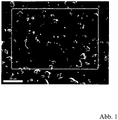
- illustration 1 a scanning electron micrograph of the structure of a cross-section through the round sample sintered at 2100°C is shown (the size of the image section is about 115 ⁇ m by 90 ⁇ m, the scale bar corresponds to 20 ⁇ m).
- the image shows a fine-grained, homogeneous structure of the microstructure.
- the high density of the structure with a very low porosity can be seen.
- the directional structure of the structure cannot be seen in this figure, since the plane of the cross-section is perpendicular to the pressing direction and thus also to the orientation of the structure.
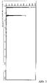
- Figure 2 shows the element distribution of the in illustration 1 boxed area of the sample, with Si shown in light and C shown in dark.
- the blank consists essentially only of the elements Si and C.
- the measurement of the grain size revealed a mean diameter of less than 10 ⁇ m for the Si-containing particles, the mean distance between these particles is less than 20 ⁇ m.
- the Si-containing particles are evenly distributed in the structure of the coating source.
- An X-ray diffractogram (XRD) of the sample shows that the dopant silicon is only present in the form of Si carbide, i.e. in a form that has reacted with the carbon, which indicates a chemical reaction that took place during the sintering process Reaction between silicon and carbon indicates.
- XRD X-ray diffractogram
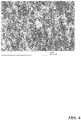
- Figure 4 shows a scanning electron micrograph of the structure of a cross section of a variant of a silicon-doped target with a Si content of 5 mol% and a carbon content of 95 mol%.
- the target was produced in a SPS system at a sintering temperature of 1500° C. (the scale bar corresponds to 10 ⁇ m) analogously to the above variants with the appropriate mixing ratio of C/Si powder.
- a directional structure can be clearly seen in the structure, which can be traced back to the pressing process in the sintering process.
- silicon-doped targets serve to deposit silicon-doped carbon layers, in particular silicon-doped amorphous carbon layers.
- the deposition of the desired layers was demonstrated using the target variant described first.
- the circular blank made of the material CSi 90/10 mol% (diameter 75 mm, thickness 5 mm) sintered at 2100° C. was soldered flat to a back plate made of copper with a diameter of 75 mm and a thickness of 3 mm using indium.
- the target obtained in this way was used in a PVD system in the DC sputtering process to coat a hard metal substrate.
- the target showed stable behavior with regard to the ignition and the stability of the plasma at powers of 200 watts (500 V and 0.4 A), 300 watts (550 V and 0.55 A) and 400 watts (570 V and 0.7A). Silicon and carbon were detected in the layers deposited on the hard metal substrate.
- Example 2 In exemplary embodiment 2, a titanium-doped coating source was produced for the deposition of titanium-doped carbon layers. Approx. 1.5 kg of a mixture of Ti powder and C powder (mean grain size d 50 of approx. 10 ⁇ m) in a mixing ratio of 10/90 mol% were used as the starting material for the circular target with a diameter of 75 mm and a thickness of 5 mm. used, which were ground wet for 4 hours in a pot roller with the addition of 5 l isopropanol and 5 kg grinding balls made of Si nitride.
- the individual production steps are analogous to the process steps in exemplary embodiment 1; the dried powder mixture was sintered at a pressure of 30 MPa and a temperature of 2100° C. in direct current passage and then mechanically processed. XRD analysis performed on cross-sections of the sintered sample showed that titanium is present in the structure only in the form of Ti-carbide through a reaction with the carbon.
- Example 3 In example 3, a target for the physical vapor deposition of carbon layers doped with chromium diboride was produced. The production steps are analogous to those in the method steps in the previous exemplary embodiments. Approx. 1.5 kg of a mixture of chromium diboride powder and C powder (mean particle size d 50 of about 10 ⁇ m) in a mixing ratio of 10/90 mol% were used as the starting material for the circular target with a diameter of 75 mm and a thickness of 5 mm , which were wet ground for 4 hours in a pot roller with the addition of 5 l isopropanol and 5 kg grinding balls made of Si nitride.
- a target for the physical vapor deposition of carbon layers doped with chromium diboride was produced. The production steps are analogous to those in the method steps in the previous exemplary embodiments. Approx. 1.5 kg of a mixture of chromium diboride powder and C powder (mean particle size d 50 of about 10 ⁇ m) in a
- the dried powder mixture was sintered at a pressure of 30 MPa and a temperature of 2100° C. to give a blank with a diameter of 85 mm and a thickness of 8 mm and was then mechanically finished.
- An XRD investigation carried out on cross sections of the sintered sample showed that the dopant is present in a form that has not reacted with the carbon.
Landscapes
- Chemical & Material Sciences (AREA)
- Engineering & Computer Science (AREA)
- Organic Chemistry (AREA)
- Materials Engineering (AREA)
- Mechanical Engineering (AREA)
- Chemical Kinetics & Catalysis (AREA)
- Metallurgy (AREA)
- Physics & Mathematics (AREA)
- Plasma & Fusion (AREA)
- Analytical Chemistry (AREA)
- Manufacturing & Machinery (AREA)
- Inorganic Chemistry (AREA)
- Ceramic Engineering (AREA)
- Structural Engineering (AREA)
- Thermal Sciences (AREA)
- Composite Materials (AREA)
- Physical Vapour Deposition (AREA)
- Carbon And Carbon Compounds (AREA)
Description
- Die vorliegende Erfindung betrifft eine Beschichtungsquelle für die physikalische Dampfphasenabscheidung von dotierten Kohlenstoffschichten, insbesondere von dotierten amorphen Kohlenstoffschichten, und ein Herstellungsverfahren für eine derartige Beschichtungsquelle.
- Amorphe Kohlenstoffschichten (engl. amorphous diamond-like carbon, DLC) sind kohlenstoffhaltige Schichten, die im Gegensatz zu Grafitschichten (besitzen kristalline Struktur und sp2 hybridisierte Kohlenstoffatome) und Diamantschichten (haben kristalline Struktur und sp3 hybridisierte Kohlenstoffatome) strukturell aus einem amorphen Netzwerk von sp2 und sp3 hybridisierten Kohlenstoffatomen bestehen. Amorphe Kohlenstoffschichten können wasserstofffrei oder wasserstoffhaltig sein und Dotierungen anderer Elemente enthalten. In VDI 2840 (Verein Deutscher Ingenieure, Kohlenstoffschichten, Grundlagen, Schichttypen und Eigenschaften) sind die verschiedenen Schichttypen amorpher Kohlenstoffschichten klassifiziert. Aufgrund sowohl grafit- als auch diamantähnlicher Strukturen liegen viele Eigenschaften von amorphen Kohlenstoffschichten zwischen denen von Grafit und Diamant. Amorphe Kohlenstoffschichten zeichnen sich durch eine diamantähnliche Härte (Härte bis zu 90 GPa) aus und haben zugleich hohe Verschleißbeständigkeit, einen geringen Reibkoeffizienten und eine gute Schichthaftung. Diese Schichten werden daher zunehmend unter anderem für tribologische Anwendungen, beispielsweise als reibungsmindernde und verschleißbeständige Beschichtungen bei Automobilkomponenten, eingesetzt. Zusätzlich weisen amorphe Kohlenstoffschichten eine ausgezeichnete biologische Verträglichkeit auf.
- Neben diesen vorteilhaften Eigenschaften ist eine beschränkte thermische Stabilität nachteilig, denn die schlechte Oxidationsbeständigkeit von amorphen Kohlenstoffschichten führt zu einer begrenzten Einsatztemperatur von etwa 350°C.
- Amorphe Kohlenstoffschichten werden in der Regel als Dünnschichten mit Schichtdicken von wenigen Mikrometern abgeschieden, üblicherweise über chemische oder physikalische Gasphasenabscheidung. Als wichtiges chemisches Gasphasenabscheidungsverfahren (engl. chemical vapour deposition, CVD) ist dabei die plasmaunterstützte chemische Gasphasenabscheidung (engl. plasma-assisted CVD (PA-CVD), auch als plasma-enabled CVD bezeichnet) zu nennen, bei der die chemische Abscheidung durch ein Plasma, üblicherweise durch eine äußere Hochfrequenz-Wechselspannung erzeugt, unterstützt wird. Die zur Herstellung von amorphen Kohlenstoffschichten gebräuchlichsten physikalischen Gasphasenabscheidungsverfahren (engl. physical vapour deposition, PVD) sind Magnetron-Kathodenzerstäubung (engl. magnetron sputter deposition) und Lichtbogenverdampfen (engl. arc-PVD, auch arc evaporation). Bei der Magnetron-Kathodenzerstäubung wird in einer Kammer ein durch ein Plasma ionisiertes Arbeitsgas (z.B. Argon oder kohlenstoffhaltige Gase) auf ein aus dem Beschichtungsmaterial gebildetes Target beschleunigt, wodurch Teilchen des Beschichtungsmaterials herausgeschlagen werden, in die Gasphase übertreten und aus der Gasphase auf dem zu beschichtenden Substrat abgeschieden werden. In der Nähe der aktiven Oberfläche des Targets ist ein zusätzliches Magnetfeld angelegt, um die Sputterrate zu erhöhen und somit den Beschichtungsvorgang zu beschleunigen. Beim Verfahren der Lichtbogenverdampfung wird das als Kathode bereitgestellte Beschichtungsmaterial durch einen über die Kathode wandernden Lichtbogen lokal geschmolzen und verdampft. Der teilweise ionisierte Beschichtungsmaterialdampf breitet sich, gegebenenfalls unterstützt durch eine zusätzlich angelegte elektrische Spannung, von der Kathode aus und kondensiert an der zu beschichtenden Substratoberfläche. Die Herstellung amorpher Kohlenstoffschichten mittels Lichtbogenverdampfung von Grafitkathoden ist aufgrund der starken Temperaturabhängigkeit der elektrischen Leitfähigkeit von Grafit sehr schwierig. Durch die geringe Beweglichkeit des Lichtbogens kommt es häufig zu sogenannten Pinning-Effekten, bei denen der Lichtbogen lokal an einer Stelle hängen bleibt, wodurch ein homogener Abtrag der Grafitkathoden behindert wird.
- Ein Vorteil von PVD Verfahren gegenüber CVD Verfahren ist, dass im Allgemeinen die thermische Belastung des Substrates bei PVD Verfahren geringer ist als bei CVD Verfahren und daher mittels PVD Verfahren auch temperatursensiblere Materialien beschichtet werden können. Bei Einsatz eines Reaktivgases kann es auch bei PVD Verfahren zu chemischen Reaktionen mit dem Arbeitsgas kommen.
- Die Eigenschaften amorpher Kohlenstoffschichten sind vielfältig und können durch Variation des Wasserstoffgehalts und geeigneter Dotierungen in weiten Bereichen eingestellt werden. Generell kommen als Dotierungsmaterial (Dotand) sowohl Metalle (karbidbildende Metalle wie beispielsweise Wolfram, Titan oder Vanadium und nicht karbidbildende Metalle wie Gold, Kupfer oder Silber) als auch nichtmetallische Elemente (beispielsweise Silizium, Sauerstoff, Stickstoff, Fluor und Bor) zur Anwendung. So kann beispielsweise die thermische Stabilität, die Verschleißbeständigkeit und der Reibungskoeffizient der Kohlenstoffschichten durch Dotierung mit Silizium, Titan, Chrom, Wolfram oder Molybdän beeinflusst werden, wobei der Anteil des Dotanden üblicherweise kleiner als 25 mol% (Molprozent) ist.
- Die Herstellung qualitativ hochwertiger dotierter amorpher Kohlenstoffschichten ist derzeit mit zahlreichen Herausforderungen verbunden. Einerseits wird die Komplexität des Beschichtungsprozesses signifikant erhöht. Bei CVD Verfahren erfolgt die Dotierung durch zusätzliches Verdampfen einer chemischen Verbindung des gewünschten Dotanden (für eine Titan-dotierte amorphe Kohlenstoffschicht beispielsweise durch Verdampfen von TiCl4), bei PVD Verfahren durch paralleles Zerstäuben (Co-sputtern) von Grafit und eines elementaren Targets bzw. Kathode (beispielsweise einer zusätzlichen Titanbeschichtungsquelle). Besonders nachteilig bei der Verwendung mehrerer Beschichtungsquellen ist die schlechte Homogenität der aufgebrachten Schichten, zudem sind in der Regel niedrigere Wachstumsraten zu erzielen. Bei der Herstellung dotierter Kohlenstoffschichten haben CVD Verfahren gegenüber PVD Verfahren den Nachteil, dass viele wichtige Dotanden wie beispielsweise Molybdän oder Wolfram nicht in einer geeigneten flüssigen bzw. gasförmigen Verbindung vorliegen. Dies ist einer der Nachteile gegenüber den PVD Verfahren.
- Zur Verbesserung der Schichthomogenität gibt es erste Ansätze, bei denen die benötigten Beschichtungsmaterialien in einem Target bzw. einer Kathode aus einem Werkstoffverbund zusammengefügt werden (Chaus et al., Surface, microstructure and optical properties of copper-doped diamond-like carbon coating deposited in pulsed cathodic arc plasma, Diamond & Related Materials 42 (2014), p 64-70). In Chaus et al. wird ein zylindrisches Kathodentarget aus Grafit (Durchmesser 32 mm) verwendet, in das Stäbe aus dem Dotanden Kupfer (Durchmesser 6 mm) eingebettet sind (sogenannte Stopfenkathode). Die Qualität der erzeugten Schichten ist allerdings für industrielle Anwendungen nicht völlig zufriedenstellend, da nichtsdestotrotz Inhomogenitäten in der Beschichtungsschicht auftreten, die auf die zeitlich variierende Zusammensetzung des verdampften Beschichtungsmaterials zurückzuführen sind. Zudem ist aufgrund unterschiedlicher Verdampfungsraten zwischen dem Grafitbereich und dem Kupferstäben die Abtragung der Kathode inhomogen und die Lebensdauer der Kathode vermindert.
- Es sind ferner Targets bekannt, bei denen ein poröser Grundkörper aus Grafit mit einer Schmelze aus einem Dotanden oder über eine Gasphase, die den Dotanden beinhaltet, infiltriert wird. Zwecks Infiltrierbarkeit muss der Grafit-Grundkörper eine offenporige Struktur haben und aus diesem Grund kann bei infiltrierten Grafit-Targets der Anteil des Dotanden nicht unterhalb eines bestimmten Schwellwerts gewählt werden. Wird die Infiltration vorzeitig beendet, um niedrige Gehalte an Dotanden einzustellen, so bleibt ein hoher Anteil an Porosität übrig. Nachteilig ist zudem, dass beim Beschichtungsprozess aufgrund des zusammenhängenden Netzwerks des Dotanden im Target Inhomogenitäten beim Materialabtrag auftreten.
- Ein Beispiel für eine Beschichtungsquelle, bei der Grafit und Dotand in einer Einheit zusammengeführt sind, wird in
JP2005/060765 - Des Weiteren beschreibt die
US 6,143,142 A die Herstellung von Beschichtungen aus Kohlenstoff und einem anderen Element und die Verwendung von Targets aus Kohlenstoff und Silizium, sowie Kohlenstoff und Aluminium. L. J. Yu et al. (Applied Surface Science 195 (2002) 107-116) beschreibt die Verwendung von ungesinterten Kathoden aus reinem Grafit oder aus AI-Ti-Grafit Kathoden. DieUS 2014/0346039 A1 beschreibt Targets mit im Target verteilten Kohlenstoff Partikeln für die Herstellung von magnetischen Aufnahmemedien. - Aufgabe der vorliegenden Erfindung ist, eine Beschichtungsquelle für die physikalische Dampfphasenabscheidung zur Herstellung von dotierten Kohlenstoffschichten, insbesondere von dotierten amorphen Kohlenstoffschichten zur Verfügung zu stellen, bei denen die bei der Verwendung von mehreren Beschichtungsquellen auftretenden vorhin genannten Nachteile vermieden bzw. reduziert werden. Die Beschichtungsquelle soll insbesondere eine möglichst homogene Verteilung des Dotanden in der abgeschiedenen Kohlenstoffschicht ermöglichen. Zudem soll sie bei einer Lichtbogenverdampfung zu keiner örtlich erhöhten Verdampfungsrate neigen. Weiters ist Aufgabe der vorliegenden Erfindung, ein Herstellungsverfahren für eine derartige Beschichtungsquelle zu schaffen.
- Diese Aufgabe wird durch ein Verfahren zur Herstellung einer Beschichtungsquelle für die Dampfphasenabscheidung von dotierten Kohlenstoffschichten gemäß Anspruch 1 und durch eine dotierte Beschichtungsquelle gemäß Anspruch 6 gelöst. Vorteilhafte Ausgestaltungen der Erfindung sind Gegenstand von abhängigen Unteransprüchen.
- Die erfindungsgemäße dotierte Beschichtungsquelle wird durch Sintern einer Pulvermischung aus kohlenstoffhaltigem Pulver (bzw. einer kohlenstoffhaltigen Pulvermischung) und Dotand-haltigem Pulver (bzw. einer Dotand-haltigen Pulvermischung) hergestellt. Sie weist Kohlenstoff als Matrixmaterial mit einem Stoffmengenanteil von mindestens 75 mol% und mindestens einen Dotanden mit einem Stoffmengenanteil zwischen 1 mol% und 25 mol%, bevorzugt zwischen 1 mol% und 20 mol%, besonders bevorzugt zwischen 2 mol% und 10 mol% auf. Vorteilhafterweise kann dabei der Stoffmengenanteil des mindestens einen Dotanden kleiner 5 mol% sein. Neben dem Dotand können in der Beschichtungsquelle übliche herstellungsbedingte Verunreinigungen wie beispielsweise Schwefel vorhanden sein, wobei die Menge an Verunreinigungen typischerweise geringer als 1000 ppm ist. Der Dotand dient der gezielten Modifikation der unter Verwendung der Beschichtungsquelle abgeschiedenen Kohlenstoffschicht.
- Der Dotand kann ein Metall oder ein Halbmetall sein. Der Dotand kann auch eine oxidische, nitridische, boridische oder silizidische Verbindung eines Metalls oder eines Halbmetalls sein. Insbesondere können als Dotand die Metalle Titan, Vanadium, Chrom, Zirkon, Niob, Molybdän, Hafnium, Tantal, Wolfram und das Halbmetall Silizium verwendet werden. Als Dotand können zudem Oxide, Nitride, Boride oder Silizide der Metalle Titan, Vanadium, Chrom, Zirkon, Niob, Molybdän, Hafnium, Tantal, Wolfram oder Oxide, Nitride, Boride des Halbmetalls Silizium verwendet werden.
- Der Dotand kann in der Beschichtungsquelle in im Wesentlichen unveränderter Form vorliegen oder mit dem Matrixmaterial Kohlenstoff während des Sintervorganges chemisch reagiert haben. Der Dotand kann auch in Form einer karbidischen Verbindung des Dotanden in das Matrixmaterial eingebracht worden sein, beispielsweise als Metallkarbid oder Halbmetallkarbid.
- Mit dem Dotanden wird in der vorliegenden Anmeldung auf ein oder mehrere Elemente oder chemische Verbindungen Bezug genommen, die, abgesehen von etwaigen Verunreinigungen, in der Beschichtungsquelle neben dem Kohlenstoff vorliegen. Wird die Beschichtungsquelle unter Verwendung eines Pulvers aus einer karbidischen Verbindung eines Dotiermaterials hergestellt oder kommt es während des Sintervorgangs zu chemischen Reaktionen zwischen dem Dotiermaterial mit dem Kohlenstoff, so wird in der vorliegenden Erfindung mit dem Dotanden also auf das Dotiermaterial Bezug genommen und nicht auf die karbidische Verbindung des Dotiermaterials. Wird beispielsweise die Beschichtungsquelle aus einem Ausgangspulver aus einem Metallkarbid bzw. einem Halbmetallkarbid hergestellt, so wird in der vorliegenden Erfindung als Dotand der Beschichtungsquelle das entsprechende Metall bzw. Halbmetall verstanden und nicht das Metallkarbid bzw. Halbmetallkarbid. Analoges gilt bei Verwendung eines Metall- bzw. Halbmetallpulvers, das beim Herstellungsprozess mit dem Kohlenstoff reagiert. Auch hier wird in der vorliegenden Erfindung als Dotand das entsprechende Metall bzw. Halbmetall verstanden und nicht die karbidische Verbindung des Metalls bzw. Halbmetalls. Beide Beschichtungsquellen führen beim Beschichtungsprozess zu einer mit dem entsprechenden Metall bzw. Halbmetall dotierten Kohlenstoffschicht.
- Die Dotierung in der Beschichtungsquelle kann, muss aber nicht zwangsläufig mit der Dotierung in der mittels der Beschichtungsquelle abgeschiedenen Kohlenstoffschicht übereinstimmen. Aufgrund von verschiedenen Vorgängen beim Beschichtungsprozess, beispielsweise chemischen Reaktionen mit dem Prozessgas, kann sich die chemische Zusammensetzung der abgeschiedenen dotierten Kohlenstoffschicht bzw. das Verhältnis zwischen Dotiermaterial und Kohlenstoff in der abgeschiedenen Kohlenstoffschicht von der Dotierung in der Beschichtungsquelle unterscheiden.
- Mit Beschichtungsquelle wird insbesondere auf ein Target bei der Magnetron-Kathodenzerstäubung bzw. auf eine Kathode bei der Lichtbogenverdampfung Bezug genommen.
- Erfindungsgemäß ist der Dotand in Partikelform in eine Kohlenstoffmatrix fein verteilt eingebettet. Dies wird durch die Herstellung der Beschichtungsquelle mittels Sintern aus pulverförmigen Komponenten erreicht. Kohlenstoff (Grafit) und Dotand liegen daher nicht wie beim Stand der Technik in separaten Beschichtungsquellen oder in einer Beschichtungsquelle in makroskopisch voneinander getrennten Bereichen, wie beispielsweise bei Stopfenkathoden oder bei durch Infiltrieren hergestellten Beschichtungsquellen, vor. Die erfindungsgemäße dotierte Beschichtungsquelle vereinfacht die Herstellung und erhöht die Qualität der damit abgeschiedenen dotierten Kohlenstoffschichten signifikant. Während bei herkömmlichen Beschichtungsquellen (getrenntes Grafit und Dotandtarget bzw. -kathode) die Betriebsparameter jeder einzelnen Beschichtungsquelle separat überwacht werden müssen, um näherungsweise homogen dotierte Schichten zu erzielen, wird bei der vorliegenden Erfindung Kohlenstoff und Dotand aus derselben Beschichtungsquelle verdampft bzw. zerstäubt. Es sind daher nur noch die Betriebsparameter für eine einzelne Beschichtungsquelle zu regeln. Das Verhältnis der Verdampfungsrate zwischen Matrixmaterial und Dotand ist weitgehend zeitunabhängig. Die Zusammensetzung des verdampften Materials ist zudem auch weitgehend ortsunabhängig und variiert örtlich kaum über die zu beschichtende Substratoberfläche. Es können daher die beim Stand der Technik vor allem bei der Beschichtung von großflächigen Substraten auftretenden Probleme vermieden werden, bei denen die Beschichtungsquellen aus Grafit und Dotand an verschiedenen Orten positioniert sind und sich die aus den einzelnen Beschichtungsquellen stammenden Elemente auf der zu beschichtenden Substratfläche nicht gleichmäßig abscheiden.
- Ein weiterer Vorteil ist, dass bei Lichtbogenverdampfung der Abtrag der als Kathode ausgebildeten Beschichtungsquelle gleichmäßiger verläuft. Die Dotand-haltigen Partikel wirken als Störelemente im Gefüge der Kathode und beeinflussen positiv die Laufeigenschaften des Lichtbogens über die Oberfläche der Kathode. Der Lichtbogen wird dadurch immer wieder unterbrochen und an anderer Stelle neu gezündet. Durch die besseren Laufeigenschaften des Lichtbogens wird auch die Qualität der abgeschiedenen Schichten verbessert. Bei der erfindungsgemäßen Kathode kommt es seltener zu Pinning-Effekten und dadurch weniger stark ausgeprägten lokalen Aufschmelzungen als bei einer reinen Grafitkathode, Abscheidungen in Form von Spritzern (Droplets) treten daher vermindert auf.
- Das Gefüge der Beschichtungsquelle weist erfindungsgemäß zumindest zwei unterschiedliche kristallografische Phasen auf, wobei zumindest eine Phase den Dotanden aufweist. Die Dotand-haltigen Partikel können also eine eigene kristallografische Phase in der Phase des Matrixmaterials Kohlenstoff ausbilden. Der Dotand kann mit dem Kohlenstoff chemisch reagieren oder in mit dem Kohlenstoff nicht reagierter Form vorliegen. In der vorliegenden Erfindung wird unter Dotand-haltigem Partikel sowohl ein Partikel, bei dem der Dotand in mit dem Kohlenstoff abreagierter Form vorliegt, als auch ein Partikel, bei dem der Dotand in mit dem Kohlenstoff nicht abreagierter Form vorliegt, verstanden.
- In einer bevorzugten Ausführungsform ist die mittlere Korngröße der Dotand-haltigen Partikel kleiner als 50µm, insbesondere kleiner als 20µm. Die Dotand-haltigen Partikel sind makroskopisch (auf einer Längenskala im mm-Bereich) gleichmäßig im Gefüge der Beschichtungsquelle verteilt. Bevorzugt ist der mittlere Abstand der Dotand-haltigen Partikel kleiner als 50µm, insbesondere kleiner als 20µm. Die geringe Größe und feinen Verteilung des Dotanden in der Kohlenstoffmatrix bewirkt eine äußerst homogene und zeitlich konstante Zusammensetzung des verdampften bzw. zerstäubten Beschichtungsmaterials, es gelingt dadurch, Kohlenstoffschichten mit sehr gleichmäßig verteiltem Dotanden abzuscheiden.
- Die Verteilung der Dotand-haltigen Partikel, die mittlere Korngröße und der mittlere Abstand wird - wie in dem Fachgebiet bekannt - anhand eines Querschnitts der Probe ermittelt. Die erhaltene Oberfläche wird dabei in ein Harz eingebettet, geschliffen, poliert und mit einem Rasterelektronenmikroskop (oder alternativ mit einem Lichtmikroskop) untersucht und quantitativ ausgewertet. Unter gleichmäßiger Verteilung der Dotand-haltigen Partikel ist zu verstehen: Betrachtet man einen Querschnitt der Probe unter einem Rasterelektronenmikroskop und wertet die Anzahl der Dotand-haltigen Partikel in verschiedenen, repräsentativen Bildausschnitten aus, so ist die Streuung der Häufigkeitsverteilung der Anzahl der Dotand-haltigen Partikel pro Bildausschnitte gering. Wählt man beispielsweise für die Größe des Bildausschnitts ein Quadrat mit einer Länge von etwa dem 25-fachen der mittleren Partikelgröße der Dotand-haltigen Partikel und ermittelt in einer Serie von 10 verschiedenen Bildausschnitten jeweils pro Bildausschnitt die Anzahl der Dotand-haltigen Partikel, die sich vollständig innerhalb des Bildausschnitts befinden, so weicht bei den einzelnen Bildausschnitten die Anzahl der Dotand-haltigen Partikel nicht mehr als um einen Faktor 3 von der (aus den 10 Bildausschnitten ermittelten) durchschnittlichen Anzahl von Dotand-haltigen Partikel pro Bildausschnitt ab.
- Die erfindungsgemäße Beschichtungsquelle wird in Form eines Targets oder als Kathode zur physikalischen Dampfphasenabscheidung von dotierten Kohlenstoffschichten, insbesondere von dotierten amorphen Kohlenstoffschichten, verwendet. Beim Beschichtungsprozess kommen bevorzugt kohlenstoffhaltige Prozessgase wie Acetylen oder Methan zum Einsatz.
- Die Erfindung betrifft auch ein Herstellungsverfahren der oben beschriebenen Beschichtungsquelle. Zur Herstellung einer derartigen Beschichtungsquelle wird von einer Pulvermischung aus kohlenstoffhaltigem Pulver und Pulver, das den gewünschten Dotanden aufweist, ausgegangen. Als kohlenstoffhaltiges Pulver können Pulver oder eine Pulvermischung aus natürlichem oder synthetischen Grafit, Koks, amorphen Kohlenstoff oder Ruß verwendet werden. Grafit, Koks und Ruß besitzen eine grafitische Kristallstruktur, Unterschiede bestehen in der Fehlerfreiheit und Größe der einzelnen Kristallite. Unter dem Dotand-haltigen Pulver wird auch eine Pulvermischung, die den Dotanden aufweist, verstanden sowie insbesondere auch ein Pulver bzw. eine Pulvermischung aus einer karbidischen Verbindung des Dotanden. Zur Herstellung einer Beschichtungsquelle für die Abscheidung einer mit einem Metall oder Halbmetall dotierten Kohlenstoffschicht kann ein Pulver des entsprechenden Metalls bzw. Halbmetalls verwendet werden. Es kann aber auch ein Pulver eines Karbids des entsprechenden Metalls oder Halbmetalls verwendet werden. Eine aus einem derartigen Karbidpulver hergestellte Beschichtungsquelle führt beim Beschichtungsprozess auch zu einer mit dem entsprechenden Metall bzw. Halbmetall dotierten Kohlenstoffschicht. Sollte eine Beschichtungsquelle zur Abscheidung von Kohlenstoffschichten mit mehreren Dotanden benötigt werden, so kann die Pulvermischung Komponenten mehrerer Dotanden aufweisen.
- Die Ausgangspulver können trocken oder nass gemahlen werden und werden in einer Mischkammer intensiv vermischt. Der Mahlvorgang kann unter Beigabe von Mahlkugeln erfolgen, wodurch Agglomerate und Klumpen aus Partikeln zerkleinert werden, eine homogene Verteilung der Mischkomponenten erzielt wird und der Mischvorgang beschleunigt wird. Die erhaltene Pulvermischung weist bevorzugt eine mittlere Partikelgröße mit einem Durchmesser kleiner als 50 µm auf. Bevorzugt weist das kohlenstoffhaltige Pulver und/oder das Dotand-haltige Pulver eine mittlere Partikelgröße mit einem Durchmesser kleiner als 50 µm auf, wodurch eine äußerst homogene Verteilung des Dotanden in der Beschichtungsquelle erzielt werden kann. Es wird ein geeignetes Mischverhältnis zwischen Dotand und kohlenstoffhaltigem Pulver eingestellt, sodass nach dem Sinterprozess ein Formkörper mit einem Kohlenstoffanteil von mindestens 75 mol% und mindestens einem Dotanden mit einem Anteil zwischen 1 mol% und 25 mol%, insbesondere zwischen 1 mol% und 20 mol%, erhalten wird.
- Nach dem Mahlprozess wird die Pulvermischung in ein Formwerkzeug, beispielsweise in eine Grafitform, eingefüllt und bei Temperaturen von 1300°C bis 3000°C, in geeigneter Atmosphäre gesintert. Der Sinterprozess erfolgt insbesondere in inerter oder reduzierender Atmosphäre oder im Vakuum. Der Sinterprozess erfolgt erfindungsgemäß druckunterstützt, d.h. das Sintern erfolgt unter Verdichten der Pulvermischung bei einem angelegten mechanischen Druck von 5 bis 50 MPa. Der mechanische Druck wird vorteilhafterweise beim Aufheizen stufenweise aufgebracht und eine gewisse Zeit aufrechterhalten. Erfindungsgemäße Sinterverfahren für die Beschichtungsquelle sind rasche Heißpressverfahren, beispielsweise über Heizleiter beheiztes Heißpressen oder induktiv beheiztes Heißpressen, oder Sinterverfahren mittels direkten Stromdurchgang (beispielsweise Spark Plasma Sintern). Während beim Sintern im direktem Stromdurchgang die Wärme intern durch einen durch das Pulver geführten Stromfluss erzeugt wird, wird beim Heißpressen die Wärme von außerhalb zugeführt. Diese Verfahren zeichnen sich durch hohe Heiz- und Abkühlraten und kurze Prozesszeiten aus. Erfindungsgemäß weisen die so hergestellten Formkörper eine hohe Dichte mit mindestens 80%, bevorzugt mit mindestens 90% der theoretischen Dichte auf. Wird die Pulvermischung beim Sintervorgang in uniaxialer Richtung gepresst, so entsteht ein Formkörper, bei dem das Gefüge eine gerichtete Struktur aufweist, die in eine Richtung normal zur Pressrichtung ausgerichtet ist, das Gefüge weist also eine bevorzugte Ausrichtung auf. Optional kann der gesinterte Formkörper nach dem Sintern zur Grafitierung bei Temperaturen im Bereich von 2000°C bis 3000°C ohne zusätzlich angelegten äußeren Druck wärmebehandelt werden. Durch diese Hochtemperaturbehandlung wird bewirkt, dass die Größe und der Anteil der Grafitkristallite zunehmen, außerdem wird die thermische und elektrische Leitfähigkeit des Formkörpers verbessert. Gleichzeitig wird der Formkörper reiner, da (abgesehen von den gewünschten Dotanden) eventuelle Verunreinigungen verdampfen.
- Abschließend wird der gesinterte Formkörper mechanisch, beispielsweise durch spanabhebende Werkzeuge, zur gewünschten Endform der Beschichtungsquelle verarbeitet.
- Die Herstellung der erfindungsgemäßen dotierten Grafit-Beschichtungsquelle hat gegenüber der Herstellung einer reinen Grafit-Beschichtungsquelle einen wichtigen Vorteil. Reiner Kohlenstoff (Grafit) ist schwer sinterbar, da für den Zusammenhalt des Kohlenstoffpulvers eine zusätzliche Bindemittelmatrix erforderlich ist. Üblicherweise kommen hierfür Peche oder Polymere mit hohem Kohlenstoffgehalt zum Einsatz, die in einem thermischen Behandlungsschritt in Kohlenstoff umgesetzt werden. Bei der Herstellung einer dotierten Kohlenstoff-Beschichtungsquelle wird durch die Zugabe des Dotanden der Sintervorgang unterstützt, teilweise durch die Reaktion der Dotanden mit dem Kohlenstoff. Es wird zudem eine bessere Verdichtung des Formkörpers erreicht.
- Im Folgenden wird die Erfindung anhand von drei Ausführungsbeispielen und dazugehörigen Abbildungen näher erläutert. Ausführungsbeispiel 1 betrifft Varianten von mit dem Halbmetall Silizium dotierten Beschichtungsquellen, Ausführungsbeispiel 2 eine mit dem Metall Titan dotierte Beschichtungsquelle, und Ausführungsbeispiel 3 betrifft eine mit der chemischen Verbindung Chromdiborid dotierte Beschichtungsquelle.
- Ausführungsbeispiel 1:
Als Ausführungsbeispiel 1 wurde ein rondenförmiges Target mit 75 mm Durchmesser und 5 mm Dicke aus einer Pulvermischung aus Grafit (C) und Silizium (Si) hergestellt. Als Ausgangsmaterial wurden ca. 1,5 kg einer Mischung aus Si Pulver und C Pulver (mittlere Korngröße d 50 von etwa 10 µm) im Mischverhältnis von 10/90 mol% verwendet, die unter Zugabe von 5 I Isopropanol und 5 kg Mahlkugeln aus Si-Nitrid 4 Stunden lang in einem Topfroller nass gemahlen wurden. Nach Abtrennung der Mahlkugeln wurde der Pulveransatz durch Verdampfen des Alkohols bei ca. 100°C getrocknet und anschließend in einer Siebanlage mit einer Maschenweite von 1 mm fraktioniert. Die chemische Analyse des dadurch entstandenen Si/C Pulveransatzes ergab einen Si-Anteil von 10 mol % und einen Kohlenstoffgehalt von 90 mol%. Die Pulvermischung wurde anschließend in einer Spark-Plasma-Sinter-Anlage (SPS Anlage) unter Verwendung von Grafit-Presswerkzeugen bei einem Pressdruck von 30 MPa verdichtet und bei einer Temperatur von 2100°C zu einer Ronde mit 85 mm Durchmesser und 8 mm Dicke in direktem Stromdurchgang gesintert. Es wurde dabei bei einer Sintertemperatur von 2100°C eine Dichte von 1,90 g/cm3 erzielt, was 88 % der theoretischen Dichte des Materials entspricht. Die gesinterte Ronde wurde durch Zerspanung zu einem Target mit 75 mm Durchmesser und 5 mm Dicke endbearbeitet. - Es wurden zusätzliche Varianten (Mischverhältnis von C zu Si- Pulver: 90/10 mol%) bei den Sintertemperaturen 1500°C und 1800°C hergestellt, bei denen eine Dichte von 1,77 g/cm3 (83 % der theoretischen Dichte) (bei 1500°C) bzw. eine Dichte von 1,78 g/cm3 (83% der theoretischen Dichte) (bei 1800°C) erzielt wurde.
- Zur Analyse der gesinterten Ronde wurden aus der Ronde Proben ausgeschnitten und im Querschliff mittels Rasterelektronenmikroskopie und röntgenographischer Phasenanalyse analysiert.
- In
Abbildung 1 ist eine rasterelektronenmikroskopische Aufnahme des Gefüges eines Querschliffs durch die bei 2100°C gesinterte Rondenprobe dargestellt (die Größe des Bildausschnitts beträgt etwa 115 µm mal 90 µm, der Maßstabsbalken entspricht 20 µm). In der Aufnahme zeigt sich eine feinkörnige, homogene Struktur des Gefüges. Darüber hinaus ist die hohe Dichte des Gefüges mit einer sehr geringen Porosität zu sehen. In dieser Abbildung ist die gerichtete Struktur des Gefüges nicht erkennbar, da die Ebene des Querschliffs senkrecht zur Pressrichtung und damit auch auf die Ausrichtung des Gefüges.Abbildung 2 zeigt die mittels energiedispersiver Röntgenspektroskopie (EDX) ermittelte Elementverteilung des inAbbildung 1 umrahmten Bereichs der Probe, wobei Si hell und C dunkel dargestellt ist. Aus der EDX Analyse (inAbbildung 3 ist die Anzahl der Zählimpulse als Funktion der Energie in keV dargestellt) ergibt sich, dass die Ronde im Wesentlichen nur aus den Elementen Si und C besteht. Die Messung der Korngröße ergab für die Si-haltigen Partikel einen mittleren Durchmesser kleiner als 10 µm, der mittlere Abstand dieser Partikel ist kleiner als 20 µm. Die Si-haltigen Partikel sind im Gefüge der Beschichtungsquelle gleichmäßig verteilt. - Ein Röntgen-Diffraktogramm (XRD) der Probe zeigt, dass der Dotand Silizium nur in Form von Si-Karbid vorliegt, also in mit dem Kohlenstoff abreagierter Form, was auf eine während des Sintervorgangs abgelaufene chemische Reaktion zwischen Silizium und Kohlenstoff hinweist. Es liegen im Gefüge also zwei unterschiedliche kristallographische Phasen, eine C-Phase und eine Si-Karbid-Phase, vor.
-
Abbildung 4 zeigt eine rasterelektronenmikroskopische Aufnahme des Gefüges eines Querschliffs einer Variante eines mit Silizium dotierten Targets mit einem Si-Anteil von 5 mol% und einem Kohlenstoffgehalt von 95 mol%. Das Target wurde analog zu den obigen Varianten mit entsprechendem Mischverhältnis C/Si-Pulver in einer SPS-Anlage bei einer Sintertemperatur von 1500°C hergestellt (der Maßstabsbalken entspricht 10 µm). Im Gefüge ist deutlich eine gerichtete Struktur erkennbar, die auf den Pressvorgang im Sintervorgang zurückzuführen ist. - Diese Varianten von mit Silizium dotierten Targets dienen zur Abscheidung von mit Silizium dotierten Kohlenstoffschichten, insbesondere von mit Silizium dotierten amorphen Kohlenstoffschichten. Die Abscheidung der gewünschten Schichten wurde anhand des zuerst beschriebenen Targetvariante demonstriert. Die bei 2100°C gesinterte Ronde aus dem Werkstoff CSi 90/10 mol% (Durchmesser 75 mm, Dicke 5 mm) wurde mittels Indium auf eine Rückplatte aus Kupfer mit einem Durchmesser von 75 mm und einer Stärke von 3 mm flächig gelötet. Das so erhaltene Target wurde in einer PVD Anlage im DC Sputterprozess zur Beschichtung eines Substrats aus Hartmetall eingesetzt. Das Target zeigte dabei ein stabiles Verhalten in Bezug auf die Zündung und die Stabilität des Plasmas bei Leistungen von 200 Watt (500 V und 0,4 A), 300 Watt (550 V und 0,55 A) und 400 Watt (570 V und 0,7 A). In den auf dem Substrat aus Hartmetall abgeschiedenen Schichten wurde Silizium und Kohlenstoff detektiert.
- Ausführungsbeispiel 2:
Im Ausführungsbeispiel 2 wurde eine mit Titan dotierte Beschichtungsquelle zur Abscheidung von mit Titan dotierten Kohlenstoffschichten hergestellt. Als Ausgangsmaterial für das rondenförmige Target mit 75 mm Durchmesser und 5 mm Dicke wurden ca. 1,5 kg einer Mischung aus Ti Pulver und C Pulver (mittlere Korngröße d 50 von etwa 10 µm) im Mischverhältnis von 10/90 mol% verwendet, die unter Zugabe von 5 l Isopropanol und 5 kg Mahlkugeln aus Si-Nitrid 4 Stunden lang in einem Topfroller nass gemahlen wurden. Die einzelnen Fertigungsschritte sind analog zu den Verfahrensschritten beim Ausführungsbeispiel 1, die getrocknete Pulvermischung wurde bei einem Pressdruck von 30 MPa und einer Temperatur von 2100°C in direktem Stromdurchgang gesintert und anschließend mechanisch bearbeitet. Die an Querschnitten der gesinterten Probe durchgeführte XRD Untersuchung zeigte, dass Titan im Gefüge durch eine Reaktion mit dem Kohlenstoff nur in der Form von Ti-Karbid vorliegt. - Ausführungsbeispiel 3:
Beim Ausführungsbeispiel 3 wurde ein Target für die physikalische Dampfphasenabscheidung von mit Chrom-Diborid dotierten Kohlenstoffschichten hergestellt. Die Herstellschritte sind analog zu den in den Verfahrensschritten bei den vorherigen Ausführungsbeispielen. Als Ausgangsmaterial für das rondenförmige Target mit 75 mm Durchmesser und 5 mm Dicke wurden ca. 1,5 kg einer Mischung aus Chrom-Diborid Pulver und C Pulver (mittlere Korngröße d 50 von etwa 10 µm) im Mischverhältnis von 10/90 mol% verwendet, die unter Zugabe von 5 l Isopropanol und 5 kg Mahlkugeln aus Si-Nitrid 4 Stunden lang in einem Topfroller nass gemahlen wurden. Die getrocknete Pulvermischung wurde bei einem Pressdruck von 30 MPa und einer Temperatur von 2100°C zu einer Ronde mit 85 mm Durchmesser und 8 mm Dicke gesintert und anschließend mechanisch nachbearbeitet. Eine an Querschnitten der gesinterten Probe durchgeführte XRD Untersuchung zeigte, dass der Dotand in mit dem Kohlenstoff nicht abreagierter Form vorliegt.
Claims (11)
- Verfahren zur Herstellung einer Beschichtungsquelle für die physikalische Dampfphasenabscheidung von dotierten Kohlenstoffschichten, wobei die Beschichtungsquelle Kohlenstoff als Matrixmaterial mit einem Anteil von mindestens 75 mol% und mindestens einen Dotanden mit einem Anteil zwischen 1 mol% und 25 mol% aufweist, wobei der Dotant in Partikelform in der Kohlenstoffmatrix feinverteilt eingebettet ist und das Gefüge der Beschichtungsquelle zumindest zwei unterschiedliche kristallographische Phasen aufweist und zumindest eine Phase den Dotanten aufweist, wobei die Beschichtungsquelle mindestens 80% theoretische Dichte aufweist, dadurch gekennzeichnet, dass dieses zumindest die folgenden Herstellschritte umfasst:• Herstellen einer Pulvermischung aus kohlenstoffhaltigem Pulver und Dotand-haltigem Pulver• Sintern der Pulvermischung mittels Sintern im direkten Stromdurchgang oder mittels Heißpressen bei Temperaturen von 1300°C bis 3000°C und einem Druck von 5MPa bis 50 MPa• Mechanisches Bearbeiten des gesinterten Formkörpers zu einer Beschichtungsquelle
- Verfahren nach Anspruch 1, dadurch gekennzeichnet, dass der Dotand ein Metall, ein Halbmetall, ein Metalloxid, ein Halbmetalloxid, ein Metallnitrid, ein Halbmetallnitrid, ein Metallborid, ein Halbmetallborid, ein Metallsilizid oder ein Halbmetallsilizid ist.
- Verfahren nach Anspruch 1 oder 2, dadurch gekennzeichnet, dass der Dotand ein Element aus der Gruppe Titan, Vanadium, Chrom, Zirkon, Niob, Molybdän, Hafnium, Tantal, Wolfram, Silizium, eine oxidische, nitridische, boridische oder silizidische Verbindung eines Elements aus der Gruppe Titan, Vanadium, Chrom, Zirkon, Niob, Molybdän, Hafnium, Tantal, Wolfram oder eine oxidische, nitridische oder boridische Verbindung von Silizium ist.
- Verfahren nach einem der vorangehenden Ansprüche, dadurch gekennzeichnet, dass das kohlenstoffhaltige Pulver und/oder das Dotand-haltige Pulver eine mittlere Partikelgröße mit einem Durchmesser kleiner als 50 µm aufweist.
- Verfahren nach einem der vorangehenden Ansprüche, dadurch gekennzeichnet, dass der gesinterte Formkörper nach dem Sinterprozess zur Grafitierung ohne zusätzlichen angelegten Druck bei Temperaturen im Bereich von 2000°C bis 3000°C wärmebehandelt wird.
- Beschichtungsquelle für die physikalische Dampfphasenabscheidung zur Herstellung von dotierten Kohlenstoffschichten, welche mittels Sintern aus pulverförmigen Komponenten hergestellt ist und Kohlenstoff als Matrixmaterial mit einem Anteil von mindestens 75 mol% und mindestens einen Dotanden mit einem Anteil zwischen 1 mol% und 25 mol% aufweist und der Dotant in Partikelform in der Kohlenstoffmatrix feinverteilt eingebettet ist und das Gefüge der Beschichtungsquelle zumindest zwei unterschiedliche kristallographische Phasen aufweist, wobei zumindest eine Phase den Dotanten aufweist und die Beschichtungsquelle eine Dichte von mindestens 80% theoretischer Dichte aufweist.
- Beschichtungsquelle nach Anspruch 6, dadurch gekennzeichnet, dass der Dotand ein Metall, ein Halbmetall, ein Metalloxid, ein Halbmetalloxid, ein Metallnitrid, ein Halbmetallnitrid, ein Metallborid, ein Halbmetallborid, ein Metallsilizid oder ein Halbmetallsilizid ist.
- Beschichtungsquelle nach Anspruch 6 oder 7, dadurch gekennzeichnet, dass der Dotand ein Element aus der Gruppe Titan, Vanadium, Chrom, Zirkon, Niob, Molybdän, Hafnium, Tantal, Wolfram, Silizium oder eine oxidische, nitridische, boridische oder silizidische Verbindung eines Elements aus der Gruppe Titan, Vanadium, Chrom, Zirkon, Niob, Molybdän, Hafnium, Tantal, Wolfram oder eine oxidische, nitridische oder boridische Verbindung von Silizium ist.
- Beschichtungsquelle nach einem der Ansprüche 6 bis 8, dadurch gekennzeichnet, dass der mittlere Abstand der Dotand-haltigen Partikel kleiner als 50µm beträgt.
- Beschichtungsquelle nach einem der Ansprüche 6 bis 9, dadurch gekennzeichnet, dass das Gefüge eine gerichtete Struktur aufweist.
- Verwendung einer Beschichtungsquelle nach einem der Ansprüche 6 bis 10 zum Abscheiden von dotierten Kohlenstoffschichten.
Applications Claiming Priority (2)
| Application Number | Priority Date | Filing Date | Title |
|---|---|---|---|
| ATGM70/2015U AT14701U1 (de) | 2015-03-19 | 2015-03-19 | Beschichtungsquelle zur Herstellung dotierter Kohlenstoffschichten |
| PCT/EP2016/000462 WO2016146256A1 (de) | 2015-03-19 | 2016-03-15 | Beschichtungsquelle zur herstellung dotierter kohlenstoffschichten |
Publications (2)
| Publication Number | Publication Date |
|---|---|
| EP3271497A1 EP3271497A1 (de) | 2018-01-24 |
| EP3271497B1 true EP3271497B1 (de) | 2022-09-07 |
Family
ID=55656514
Family Applications (1)
| Application Number | Title | Priority Date | Filing Date |
|---|---|---|---|
| EP16713290.1A Active EP3271497B1 (de) | 2015-03-19 | 2016-03-15 | Beschichtungsquelle und verfahren zur herstellung dotierter kohlenstoffschichten |
Country Status (7)
| Country | Link |
|---|---|
| US (1) | US10781102B2 (de) |
| EP (1) | EP3271497B1 (de) |
| JP (1) | JP6874930B2 (de) |
| KR (1) | KR102622490B1 (de) |
| CN (1) | CN107406971B (de) |
| AT (1) | AT14701U1 (de) |
| WO (1) | WO2016146256A1 (de) |
Cited By (2)
| Publication number | Priority date | Publication date | Assignee | Title |
|---|---|---|---|---|
| AT18142U1 (de) * | 2023-02-08 | 2024-03-15 | Plansee Composite Mat Gmbh | Siliziumhaltige übergangsmetallboridverdampfungsquelle |
| DE102023129550A1 (de) | 2023-10-26 | 2025-04-30 | Oerlikon Surface Solutions Ag, Pfäffikon | Schicht mit eingebauten abrasiven Partikeln |
Families Citing this family (11)
| Publication number | Priority date | Publication date | Assignee | Title |
|---|---|---|---|---|
| DE102017124656A1 (de) | 2016-10-25 | 2018-04-26 | Schaeffler Technologies AG & Co. KG | Verfahren zur Herstellung einer Kohlenstoffbeschichtung |
| KR102612989B1 (ko) | 2017-12-01 | 2023-12-11 | 어플라이드 머티어리얼스, 인코포레이티드 | 고 에칭 선택성 비정질 탄소 막 |
| CN107937873B (zh) * | 2017-12-22 | 2023-11-14 | 深圳先进技术研究院 | 碳掺杂的过渡金属硼化物涂层、碳-过渡金属硼化物复合涂层、制备方法及应用和切削工具 |
| FR3082527B1 (fr) * | 2018-06-18 | 2020-09-18 | Hydromecanique & Frottement | Piece revetue par un revetement de carbone amorphe non-hydrogene sur une sous-couche comportant du chrome, du carbone et du silicium |
| WO2020045833A1 (ko) * | 2018-08-30 | 2020-03-05 | 에스케이씨 주식회사 | 반절연 탄화규소 단결정 잉곳을 성장시키는 방법 및 탄화규소 단결정 잉곳 성장 장치 |
| DE102018125631A1 (de) | 2018-10-16 | 2020-04-16 | Schaeffler Technologies AG & Co. KG | Schichtsystem, Rollelement und Verfahren |
| JP6756886B1 (ja) * | 2019-04-26 | 2020-09-16 | Jx金属株式会社 | ニオブ酸カリウムナトリウムスパッタリングターゲット |
| KR102317512B1 (ko) * | 2019-09-11 | 2021-10-26 | 강원대학교산학협력단 | 리튬 이차 전지용 음극 활물질, 이의 제조방법 및 이를 포함하는 리튬 이차 전지 |
| US20230317424A1 (en) * | 2020-08-21 | 2023-10-05 | Lam Research Corporation | Erosion resistant plasma processing chamber components |
| CN113913735B (zh) * | 2021-09-07 | 2022-06-24 | 广州今泰科技股份有限公司 | 一种钒/钇共掺杂dlc涂层及其制备方法 |
| CN116083847B (zh) * | 2023-01-16 | 2025-03-25 | 厦门金鹭特种合金有限公司 | 一种二硼化钛硬质涂层、涂层刀具及制备方法 |
Family Cites Families (9)
| Publication number | Priority date | Publication date | Assignee | Title |
|---|---|---|---|---|
| GB9910842D0 (en) * | 1999-05-10 | 1999-07-07 | Univ Nanyang | Composite coatings |
| JP2005060765A (ja) | 2003-08-12 | 2005-03-10 | Yamaguchi Prefecture | 硬質皮膜とその製造方法 |
| WO2008044626A1 (fr) | 2006-10-13 | 2008-04-17 | Nippon Mining & Metals Co., Ltd. | CIBLE DE PULVÉRISATION DE FRITTAGE D'ALLIAGE À BASE DE Sb-Te |
| EP2270252B1 (de) * | 2008-03-17 | 2016-06-22 | JX Nippon Mining & Metals Corporation | Gesintertes target und verfahren zur herstellung von gesintertem material |
| KR20120023022A (ko) * | 2009-05-27 | 2012-03-12 | 제이엑스 닛코 닛세키 킨조쿠 가부시키가이샤 | 소결체 타겟 및 소결체의 제조 방법 |
| KR20120120127A (ko) * | 2010-04-26 | 2012-11-01 | 제이엑스 닛코 닛세키 킨조쿠 가부시키가이샤 | Sb-Te기 합금 소결체 스퍼터링 타깃 |
| AT11884U1 (de) * | 2010-05-04 | 2011-06-15 | Plansee Se | Target |
| CN102363215A (zh) * | 2011-11-04 | 2012-02-29 | 中南大学 | 铬铝合金靶材的粉末真空热压烧结制备方法 |
| CN104145306B (zh) * | 2012-06-18 | 2017-09-26 | 吉坤日矿日石金属株式会社 | 磁记录膜用溅射靶 |
-
2015
- 2015-03-19 AT ATGM70/2015U patent/AT14701U1/de not_active IP Right Cessation
-
2016
- 2016-03-15 EP EP16713290.1A patent/EP3271497B1/de active Active
- 2016-03-15 US US15/556,379 patent/US10781102B2/en active Active
- 2016-03-15 KR KR1020177026239A patent/KR102622490B1/ko active Active
- 2016-03-15 CN CN201680016783.XA patent/CN107406971B/zh active Active
- 2016-03-15 JP JP2017548472A patent/JP6874930B2/ja active Active
- 2016-03-15 WO PCT/EP2016/000462 patent/WO2016146256A1/de not_active Ceased
Cited By (2)
| Publication number | Priority date | Publication date | Assignee | Title |
|---|---|---|---|---|
| AT18142U1 (de) * | 2023-02-08 | 2024-03-15 | Plansee Composite Mat Gmbh | Siliziumhaltige übergangsmetallboridverdampfungsquelle |
| DE102023129550A1 (de) | 2023-10-26 | 2025-04-30 | Oerlikon Surface Solutions Ag, Pfäffikon | Schicht mit eingebauten abrasiven Partikeln |
Also Published As
| Publication number | Publication date |
|---|---|
| CN107406971B (zh) | 2020-07-24 |
| JP6874930B2 (ja) | 2021-05-19 |
| EP3271497A1 (de) | 2018-01-24 |
| CN107406971A (zh) | 2017-11-28 |
| AT14701U1 (de) | 2016-04-15 |
| US20180105421A1 (en) | 2018-04-19 |
| WO2016146256A1 (de) | 2016-09-22 |
| KR102622490B1 (ko) | 2024-01-08 |
| US10781102B2 (en) | 2020-09-22 |
| KR20170129749A (ko) | 2017-11-27 |
| JP2018511699A (ja) | 2018-04-26 |
Similar Documents
| Publication | Publication Date | Title |
|---|---|---|
| EP3271497B1 (de) | Beschichtungsquelle und verfahren zur herstellung dotierter kohlenstoffschichten | |
| EP4129958B1 (de) | Verfahren zur herstellung von beschichteten substraten sowie beschichtetes substrat und dessen verwendung | |
| DE60124061T2 (de) | Hartstoffschicht für Schneidwerkzeuge | |
| EP0081270B1 (de) | Verfahren zur Herstellung einer thermionischen Kathode und nach diesem Verfahren hergestellte thermionische Kathode | |
| EP2597171B1 (de) | Verfahren zur Herstellung von kubischen Zirkonoxidschichten | |
| AT14157U1 (de) | W-Ni-Sputtertarget | |
| DE10104611A1 (de) | Vorrichtung zur keramikartigen Beschichtung eines Substrates | |
| EP3426816A1 (de) | Verfahren zur herstellung einer hartstoffschicht auf einem substrat, hartstoffschicht, zerspanwerkzeug sowie beschichtungsquelle | |
| WO2023012103A1 (de) | Verfahren zur herstellung von beschichteten substraten sowie beschichtetes substrat und dessen verwendung | |
| WO2007110149A1 (de) | Gesinterter verschleissbeständiger boridwerkstoff, sinterfähige pulvermischung zur herstellung des werkstoffs, verfahren zur herstellung des werkstoffs und dessen verwendung | |
| DE19714432C2 (de) | Trägerkörper mit einer Schutzbeschichtung und Verwendung des beschichteten Trägerkörpers | |
| DE19845151A1 (de) | Verfahren zur Herstellung von verschleißfesten Verbundwerkstoffen | |
| DE4302407C2 (de) | Verfahren zur Herstellung eines mit einer Schicht aus Diamant beschichteten Elements auf Siliciumnitridbasis | |
| EP0425056A1 (de) | Verfahren zur Abscheidung mikrokristalliner Festkörperpartikel aus der Gasphase mittels Chemical Vapour Deposition (CVD) | |
| EP4430019A1 (de) | Verfahren zur behandlung von porösen substraten sowie behandeltes substrat und dessen verwendung | |
| Han et al. | Influence of nitrogen flow rate on the microstructure and properties of N and Me (Me= Cr, Zr) co-doped diamond-like carbon films | |
| WO2024165268A1 (de) | Siliziumhaltige übergangsmetallboridverdampfungsquelle | |
| DE4221659C2 (de) | Flüchtige, metallorganische Alkoxide und ihre Verwendung zur Herstellung von Mikrokompositen aus Keramik und Metall | |
| JP2016037639A (ja) | 他元素含有蒸発源、dlc膜形成方法及びdlc膜形成装置 | |
| DE3935863C2 (de) | CVD (Chemical Vapour Deposition)-Vorrichtung | |
| DE102024117726A1 (de) | Oxidationsschutzbeschichtung für diboridbasierte Ultrahochtemperaturkeramik, basierend auf elementarem Aluminium und Aluminiumoxidmischungen | |
| DE19854385A1 (de) | Verfahren zur Herstellung von Diamantverbundwerkstoffen | |
| EP1065692A2 (de) | Flächige Elektronen-Feldemissionsquelle und Verfahren zu deren Herstellung |
Legal Events
| Date | Code | Title | Description |
|---|---|---|---|
| STAA | Information on the status of an ep patent application or granted ep patent |
Free format text: STATUS: THE INTERNATIONAL PUBLICATION HAS BEEN MADE |
|
| PUAI | Public reference made under article 153(3) epc to a published international application that has entered the european phase |
Free format text: ORIGINAL CODE: 0009012 |
|
| STAA | Information on the status of an ep patent application or granted ep patent |
Free format text: STATUS: REQUEST FOR EXAMINATION WAS MADE |
|
| 17P | Request for examination filed |
Effective date: 20170926 |
|
| AK | Designated contracting states |
Kind code of ref document: A1 Designated state(s): AL AT BE BG CH CY CZ DE DK EE ES FI FR GB GR HR HU IE IS IT LI LT LU LV MC MK MT NL NO PL PT RO RS SE SI SK SM TR |
|
| AX | Request for extension of the european patent |
Extension state: BA ME |
|
| DAV | Request for validation of the european patent (deleted) | ||
| DAX | Request for extension of the european patent (deleted) | ||
| RIC1 | Information provided on ipc code assigned before grant |
Ipc: C23C 14/34 20060101ALI20160929BHEP Ipc: C23C 14/06 20060101ALI20160929BHEP Ipc: H01J 37/34 20060101ALI20160929BHEP Ipc: C01B 31/02 20181130ALI20160929BHEP Ipc: C23C 14/32 20060101ALI20160929BHEP Ipc: C23C 16/26 20060101AFI20160929BHEP |
|
| RIC1 | Information provided on ipc code assigned before grant |
Ipc: C01B 31/02 20060101ALI20160929BHEP Ipc: C23C 14/32 20060101ALI20160929BHEP Ipc: C23C 14/34 20060101ALI20160929BHEP Ipc: C23C 14/06 20060101ALI20160929BHEP Ipc: C23C 16/26 20060101AFI20160929BHEP Ipc: H01J 37/34 20060101ALI20160929BHEP |
|
| STAA | Information on the status of an ep patent application or granted ep patent |
Free format text: STATUS: EXAMINATION IS IN PROGRESS |
|
| 17Q | First examination report despatched |
Effective date: 20200520 |
|
| RIC1 | Information provided on ipc code assigned before grant |
Ipc: H01J 37/32 20060101ALI20220221BHEP Ipc: C01B 32/984 20170101ALI20220221BHEP Ipc: C01B 32/05 20170101ALI20220221BHEP Ipc: H01J 37/34 20060101ALI20220221BHEP Ipc: C23C 14/34 20060101ALI20220221BHEP Ipc: C23C 14/32 20060101ALI20220221BHEP Ipc: C23C 14/06 20060101ALI20220221BHEP Ipc: C23C 16/26 20060101AFI20220221BHEP |
|
| GRAP | Despatch of communication of intention to grant a patent |
Free format text: ORIGINAL CODE: EPIDOSNIGR1 |
|
| STAA | Information on the status of an ep patent application or granted ep patent |
Free format text: STATUS: GRANT OF PATENT IS INTENDED |
|
| INTG | Intention to grant announced |
Effective date: 20220503 |
|
| GRAS | Grant fee paid |
Free format text: ORIGINAL CODE: EPIDOSNIGR3 |
|
| GRAA | (expected) grant |
Free format text: ORIGINAL CODE: 0009210 |
|
| STAA | Information on the status of an ep patent application or granted ep patent |
Free format text: STATUS: THE PATENT HAS BEEN GRANTED |
|
| AK | Designated contracting states |
Kind code of ref document: B1 Designated state(s): AL AT BE BG CH CY CZ DE DK EE ES FI FR GB GR HR HU IE IS IT LI LT LU LV MC MK MT NL NO PL PT RO RS SE SI SK SM TR |
|
| REG | Reference to a national code |
Ref country code: GB Ref legal event code: FG4D Free format text: NOT ENGLISH |
|
| REG | Reference to a national code |
Ref country code: CH Ref legal event code: EP Ref country code: AT Ref legal event code: REF Ref document number: 1517094 Country of ref document: AT Kind code of ref document: T Effective date: 20220915 |
|
| REG | Reference to a national code |
Ref country code: DE Ref legal event code: R096 Ref document number: 502016015248 Country of ref document: DE |
|
| REG | Reference to a national code |
Ref country code: IE Ref legal event code: FG4D Free format text: LANGUAGE OF EP DOCUMENT: GERMAN |
|
| REG | Reference to a national code |
Ref country code: SE Ref legal event code: TRGR |
|
| REG | Reference to a national code |
Ref country code: NL Ref legal event code: FP |
|
| REG | Reference to a national code |
Ref country code: LT Ref legal event code: MG9D |
|
| PG25 | Lapsed in a contracting state [announced via postgrant information from national office to epo] |
Ref country code: RS Free format text: LAPSE BECAUSE OF FAILURE TO SUBMIT A TRANSLATION OF THE DESCRIPTION OR TO PAY THE FEE WITHIN THE PRESCRIBED TIME-LIMIT Effective date: 20220907 Ref country code: NO Free format text: LAPSE BECAUSE OF FAILURE TO SUBMIT A TRANSLATION OF THE DESCRIPTION OR TO PAY THE FEE WITHIN THE PRESCRIBED TIME-LIMIT Effective date: 20221207 Ref country code: LV Free format text: LAPSE BECAUSE OF FAILURE TO SUBMIT A TRANSLATION OF THE DESCRIPTION OR TO PAY THE FEE WITHIN THE PRESCRIBED TIME-LIMIT Effective date: 20220907 Ref country code: LT Free format text: LAPSE BECAUSE OF FAILURE TO SUBMIT A TRANSLATION OF THE DESCRIPTION OR TO PAY THE FEE WITHIN THE PRESCRIBED TIME-LIMIT Effective date: 20220907 Ref country code: FI Free format text: LAPSE BECAUSE OF FAILURE TO SUBMIT A TRANSLATION OF THE DESCRIPTION OR TO PAY THE FEE WITHIN THE PRESCRIBED TIME-LIMIT Effective date: 20220907 Ref country code: ES Free format text: LAPSE BECAUSE OF FAILURE TO SUBMIT A TRANSLATION OF THE DESCRIPTION OR TO PAY THE FEE WITHIN THE PRESCRIBED TIME-LIMIT Effective date: 20220907 |
|
| PG25 | Lapsed in a contracting state [announced via postgrant information from national office to epo] |
Ref country code: HR Free format text: LAPSE BECAUSE OF FAILURE TO SUBMIT A TRANSLATION OF THE DESCRIPTION OR TO PAY THE FEE WITHIN THE PRESCRIBED TIME-LIMIT Effective date: 20220907 Ref country code: GR Free format text: LAPSE BECAUSE OF FAILURE TO SUBMIT A TRANSLATION OF THE DESCRIPTION OR TO PAY THE FEE WITHIN THE PRESCRIBED TIME-LIMIT Effective date: 20221208 |
|
| PG25 | Lapsed in a contracting state [announced via postgrant information from national office to epo] |
Ref country code: SM Free format text: LAPSE BECAUSE OF FAILURE TO SUBMIT A TRANSLATION OF THE DESCRIPTION OR TO PAY THE FEE WITHIN THE PRESCRIBED TIME-LIMIT Effective date: 20220907 Ref country code: RO Free format text: LAPSE BECAUSE OF FAILURE TO SUBMIT A TRANSLATION OF THE DESCRIPTION OR TO PAY THE FEE WITHIN THE PRESCRIBED TIME-LIMIT Effective date: 20220907 Ref country code: PT Free format text: LAPSE BECAUSE OF FAILURE TO SUBMIT A TRANSLATION OF THE DESCRIPTION OR TO PAY THE FEE WITHIN THE PRESCRIBED TIME-LIMIT Effective date: 20230109 |
|
| PG25 | Lapsed in a contracting state [announced via postgrant information from national office to epo] |
Ref country code: SK Free format text: LAPSE BECAUSE OF FAILURE TO SUBMIT A TRANSLATION OF THE DESCRIPTION OR TO PAY THE FEE WITHIN THE PRESCRIBED TIME-LIMIT Effective date: 20220907 Ref country code: PL Free format text: LAPSE BECAUSE OF FAILURE TO SUBMIT A TRANSLATION OF THE DESCRIPTION OR TO PAY THE FEE WITHIN THE PRESCRIBED TIME-LIMIT Effective date: 20220907 Ref country code: IS Free format text: LAPSE BECAUSE OF FAILURE TO SUBMIT A TRANSLATION OF THE DESCRIPTION OR TO PAY THE FEE WITHIN THE PRESCRIBED TIME-LIMIT Effective date: 20230107 Ref country code: EE Free format text: LAPSE BECAUSE OF FAILURE TO SUBMIT A TRANSLATION OF THE DESCRIPTION OR TO PAY THE FEE WITHIN THE PRESCRIBED TIME-LIMIT Effective date: 20220907 |
|
| REG | Reference to a national code |
Ref country code: DE Ref legal event code: R097 Ref document number: 502016015248 Country of ref document: DE |
|
| PG25 | Lapsed in a contracting state [announced via postgrant information from national office to epo] |
Ref country code: AL Free format text: LAPSE BECAUSE OF FAILURE TO SUBMIT A TRANSLATION OF THE DESCRIPTION OR TO PAY THE FEE WITHIN THE PRESCRIBED TIME-LIMIT Effective date: 20220907 |
|
| PLBE | No opposition filed within time limit |
Free format text: ORIGINAL CODE: 0009261 |
|
| STAA | Information on the status of an ep patent application or granted ep patent |
Free format text: STATUS: NO OPPOSITION FILED WITHIN TIME LIMIT |
|
| PG25 | Lapsed in a contracting state [announced via postgrant information from national office to epo] |
Ref country code: DK Free format text: LAPSE BECAUSE OF FAILURE TO SUBMIT A TRANSLATION OF THE DESCRIPTION OR TO PAY THE FEE WITHIN THE PRESCRIBED TIME-LIMIT Effective date: 20220907 |
|
| 26N | No opposition filed |
Effective date: 20230608 |
|
| PG25 | Lapsed in a contracting state [announced via postgrant information from national office to epo] |
Ref country code: SI Free format text: LAPSE BECAUSE OF FAILURE TO SUBMIT A TRANSLATION OF THE DESCRIPTION OR TO PAY THE FEE WITHIN THE PRESCRIBED TIME-LIMIT Effective date: 20220907 |
|
| PG25 | Lapsed in a contracting state [announced via postgrant information from national office to epo] |
Ref country code: MC Free format text: LAPSE BECAUSE OF FAILURE TO SUBMIT A TRANSLATION OF THE DESCRIPTION OR TO PAY THE FEE WITHIN THE PRESCRIBED TIME-LIMIT Effective date: 20220907 |
|
| REG | Reference to a national code |
Ref country code: BE Ref legal event code: MM Effective date: 20230331 |
|
| PG25 | Lapsed in a contracting state [announced via postgrant information from national office to epo] |
Ref country code: LU Free format text: LAPSE BECAUSE OF NON-PAYMENT OF DUE FEES Effective date: 20230315 |
|
| REG | Reference to a national code |
Ref country code: IE Ref legal event code: MM4A |
|
| PG25 | Lapsed in a contracting state [announced via postgrant information from national office to epo] |
Ref country code: IE Free format text: LAPSE BECAUSE OF NON-PAYMENT OF DUE FEES Effective date: 20230315 |
|
| PG25 | Lapsed in a contracting state [announced via postgrant information from national office to epo] |
Ref country code: BE Free format text: LAPSE BECAUSE OF NON-PAYMENT OF DUE FEES Effective date: 20230331 |
|
| REG | Reference to a national code |
Ref country code: AT Ref legal event code: MM01 Ref document number: 1517094 Country of ref document: AT Kind code of ref document: T Effective date: 20230315 |
|
| PG25 | Lapsed in a contracting state [announced via postgrant information from national office to epo] |
Ref country code: IT Free format text: LAPSE BECAUSE OF FAILURE TO SUBMIT A TRANSLATION OF THE DESCRIPTION OR TO PAY THE FEE WITHIN THE PRESCRIBED TIME-LIMIT Effective date: 20220907 |
|
| PG25 | Lapsed in a contracting state [announced via postgrant information from national office to epo] |
Ref country code: AT Free format text: LAPSE BECAUSE OF NON-PAYMENT OF DUE FEES Effective date: 20230315 |
|
| PG25 | Lapsed in a contracting state [announced via postgrant information from national office to epo] |
Ref country code: AT Free format text: LAPSE BECAUSE OF NON-PAYMENT OF DUE FEES Effective date: 20230315 |
|
| PG25 | Lapsed in a contracting state [announced via postgrant information from national office to epo] |
Ref country code: BG Free format text: LAPSE BECAUSE OF FAILURE TO SUBMIT A TRANSLATION OF THE DESCRIPTION OR TO PAY THE FEE WITHIN THE PRESCRIBED TIME-LIMIT Effective date: 20220907 |
|
| PG25 | Lapsed in a contracting state [announced via postgrant information from national office to epo] |
Ref country code: BG Free format text: LAPSE BECAUSE OF FAILURE TO SUBMIT A TRANSLATION OF THE DESCRIPTION OR TO PAY THE FEE WITHIN THE PRESCRIBED TIME-LIMIT Effective date: 20220907 |
|
| PGFP | Annual fee paid to national office [announced via postgrant information from national office to epo] |
Ref country code: SE Payment date: 20250321 Year of fee payment: 10 |
|
| PGFP | Annual fee paid to national office [announced via postgrant information from national office to epo] |
Ref country code: DE Payment date: 20250319 Year of fee payment: 10 |
|
| PGFP | Annual fee paid to national office [announced via postgrant information from national office to epo] |
Ref country code: NL Payment date: 20250319 Year of fee payment: 10 |
|
| PGFP | Annual fee paid to national office [announced via postgrant information from national office to epo] |
Ref country code: FR Payment date: 20250325 Year of fee payment: 10 Ref country code: CZ Payment date: 20250307 Year of fee payment: 10 |
|
| PGFP | Annual fee paid to national office [announced via postgrant information from national office to epo] |
Ref country code: GB Payment date: 20250321 Year of fee payment: 10 |
|
| PGFP | Annual fee paid to national office [announced via postgrant information from national office to epo] |
Ref country code: CH Payment date: 20250401 Year of fee payment: 10 |
|
| PG25 | Lapsed in a contracting state [announced via postgrant information from national office to epo] |
Ref country code: CY Free format text: LAPSE BECAUSE OF FAILURE TO SUBMIT A TRANSLATION OF THE DESCRIPTION OR TO PAY THE FEE WITHIN THE PRESCRIBED TIME-LIMIT; INVALID AB INITIO Effective date: 20160315 |
|
| PG25 | Lapsed in a contracting state [announced via postgrant information from national office to epo] |
Ref country code: HU Free format text: LAPSE BECAUSE OF FAILURE TO SUBMIT A TRANSLATION OF THE DESCRIPTION OR TO PAY THE FEE WITHIN THE PRESCRIBED TIME-LIMIT; INVALID AB INITIO Effective date: 20160315 |
|
| PG25 | Lapsed in a contracting state [announced via postgrant information from national office to epo] |
Ref country code: TR Free format text: LAPSE BECAUSE OF FAILURE TO SUBMIT A TRANSLATION OF THE DESCRIPTION OR TO PAY THE FEE WITHIN THE PRESCRIBED TIME-LIMIT Effective date: 20220907 |