EP3266574B1 - Vorrichtung und verfahren zum verbringen von isoliermaterialien in lochziegel - Google Patents
Vorrichtung und verfahren zum verbringen von isoliermaterialien in lochziegel Download PDFInfo
- Publication number
- EP3266574B1 EP3266574B1 EP17000974.0A EP17000974A EP3266574B1 EP 3266574 B1 EP3266574 B1 EP 3266574B1 EP 17000974 A EP17000974 A EP 17000974A EP 3266574 B1 EP3266574 B1 EP 3266574B1
- Authority
- EP
- European Patent Office
- Prior art keywords
- insulating materials
- brick
- holes
- elements
- perforated brick
- Prior art date
- Legal status (The legal status is an assumption and is not a legal conclusion. Google has not performed a legal analysis and makes no representation as to the accuracy of the status listed.)
- Active
Links
Images


Classifications
-
- B—PERFORMING OPERATIONS; TRANSPORTING
- B28—WORKING CEMENT, CLAY, OR STONE
- B28B—SHAPING CLAY OR OTHER CERAMIC COMPOSITIONS; SHAPING SLAG; SHAPING MIXTURES CONTAINING CEMENTITIOUS MATERIAL, e.g. PLASTER
- B28B11/00—Apparatus or processes for treating or working the shaped or preshaped articles
- B28B11/04—Apparatus or processes for treating or working the shaped or preshaped articles for coating or applying engobing layers
- B28B11/042—Apparatus or processes for treating or working the shaped or preshaped articles for coating or applying engobing layers with insulating material
- B28B11/043—Apparatus or processes for treating or working the shaped or preshaped articles for coating or applying engobing layers with insulating material filling cavities or chambers of hollow blocks
Definitions
- the invention relates to a device for introducing insulating materials into the holes of at least one perforated brick, the holes of the perforated brick representing a hole pattern.
- the insulating materials are preferably mineral fiber insulating materials such. B. glass wool or rock wool, which are present as strip-shaped sections.
- the device comprises a frame, a brick receptacle which can be supported on the frame, a suction device which causes a pressure difference in the holes of the perforated brick, and a receiving device arranged above the brick receptacle.
- the receiving device has receiving elements corresponding to the hole pattern of the holes in the perforated brick, which are designed to receive the strip-shaped insulating materials.
- the invention relates to a method for introducing precut insulating materials, in particular strip-shaped insulating materials such as mineral wool, into holes of at least one perforated brick that represent a perforated pattern.
- the pre-cut insulating materials are introduced into a receiving device arranged above a brick receptacle and transferred into the holes by applying a pressure difference between the ends of the insulating materials facing the hole pattern and the opposite ends.
- Perforated bricks also called hollow bricks, are masonry bricks that are provided with holes and perforated overall to reduce weight and improve thermal insulation.
- Perforated bricks have a lower bulk density than solid bricks, since the mass is controlled by the percentage of holes and the number of pores and the pore volume or the selection of raw materials.
- the broken bricks can be made lighter by using combustible materials such as polystyrene balls, sawdust, paper fibers or the like and provided with better thermal insulation. Polystyrene beads added to the broken brick, for example, burn during the burning process of the broken brick and leave air pores in the brick.
- the holes can be filled with insulating materials.
- the insulating materials can be in the form of flakes or granules, for example.
- Pre-cut insulation materials can e.g. B. be brought into the holes of a brick by plugging or by applying a pressure difference.
- pre-cut strip-shaped insulating materials are fed from above to a brick in a brick receptacle and the insulating materials are brought into the holes of the perforated brick via a pressure difference
- EP-A2-2 431 145 discloses a device for introducing pre-cut insulating materials, in particular strip-shaped insulating materials such as mineral wool, into holes of at least one perforated brick which represent a hole pattern, comprising a frame, a brick holder that can be supported on the frame, and a receiving device arranged above the brick holder, with the hole pattern in number and arrangement the holes of the perforated brick corresponding receiving elements, which are designed to receive the complete strip-shaped insulating materials, wherein between the receiving device and the brick receptacle, an alignment unit that can be raised and lowered in the vertical direction with alignment elements corresponding in number and arrangement to the hole pattern of the holes of the perforated brick for aligning the through the receiving elements completely received strip-shaped insulating materials are arranged on the hole pattern of the holes of the perforated brick.
- a further object of the present invention is to create a method for introducing precut insulating materials, in particular strip-shaped insulating materials such as mineral wool, into holes of at least one perforated brick that represent a hole pattern, with which insulating materials can be reliably introduced into the holes of a perforated brick.
- the device of the generic type is characterized by the features of claim 1, with an alignment unit that can be raised and lowered in the vertical direction with alignment elements corresponding to the hole pattern of the holes of the perforated brick for aligning the strip-shaped insulating materials between the receiving device and the brick receiving element is arranged on the hole pattern of the holes of the perforated brick.
- the strip-shaped insulating materials are introduced into the receiving device above the brick receiving means.
- the alignment unit is located directly under the receiving device, so that the strip-shaped insulating materials are guided through both the receiving device and the alignment unit when they are fed.
- the alignment unit is then lowered in the direction of the perforated brick, the alignment elements arranged in the alignment unit aligning the freely hanging end of the strip-shaped insulating materials facing the perforated brick with the holes in the perforated brick, so that the ends of the insulating materials open when a pressure difference is applied the holes are aligned. Because of the pressure difference between the opposite ends of the strip-shaped insulating materials, they are brought into the holes of the perforated brick.
- the feeding of the insulating materials is possible independently of the introduction of the insulating materials into the perforated brick.
- the receiving device has clamping elements on the receiving elements which are used to temporarily fix the strip-shaped insulating materials.
- the receiving device is designed so that it can be raised and lowered in the vertical direction, and this movement can also take place independently of the alignment unit.
- the clamping elements are preferably designed as sheets arranged opposite one another and displaceable relative to one another in the horizontal direction, the sheets each having recesses corresponding to the hole pattern of the holes in the perforated brick.
- the insulation materials can be specified or released by simply moving one or both sheets.
- Gripping elements are advantageously arranged on the metal sheets. These gripping elements protrude from the clamping plates and are advantageously aligned in the direction of the brick holder. The formation of gripping elements enables the release or fixing of the strip-shaped insulating materials in the immediate vicinity of the surface of the perforated brick.
- the gripping elements are designed such that they can be introduced into the holes of the perforated brick in a closed position and release the strip-shaped insulating materials within the perforated brick. This makes it possible for the ends of the strip-shaped insulating materials to end flush with the surface of the perforated brick. This can be done, for example, by designing the gripping elements by means of spring plates arranged like tweezers.
- the receiving elements of the receiving device are preferably designed to be larger in their geometry than the holes in the perforated bricks, at least on their side facing away from the brick receiving element. If the receiving elements have clamping elements which are variable in size, then these are preferably designed larger in their open position than the holes in the perforated bricks. Such a shaping facilitates the introduction of the strip-shaped insulating materials into the receiving device.
- the alignment elements on the alignment unit are preferably designed to be larger in their geometry than the holes in the perforated bricks, at least on their side facing away from the brick receptacle. This facilitates the introduction of the strip-shaped insulating materials into the alignment elements of the alignment unit.
- the brick receptacle of the device has fixing elements for fixing and aligning the perforated brick in the longitudinal and transverse directions.
- the brick is fixed during the introduction process and aligned in a position in which the holes of the perforated brick are in congruence with the alignment elements of the alignment unit and the receiving elements of the receiving device. These elements are thus aligned with the holes in the perforated brick. This increases the reliability for introducing the strip-shaped insulating materials into the holes of the perforated brick.
- the device preferably has a feed device for the insulating materials.
- the feed device has a number and arrangement of the hole pattern Holes of the perforated brick adapted feed elements. Feed elements can be inserted into and removed from the receiving elements of the receiving device.
- the receiving elements are preferably designed as spiked grippers. The feed device picks up the strip-shaped insulating materials and introduces them into the receiving elements of the receiving device.
- the strip-shaped insulating materials are fixed in the receiving device, preferably by clamping elements.
- the feed device can then be removed from the receiving device, the strip-shaped insulating materials remaining in the receiving device.
- the introduction of the strip-shaped insulating materials into the holes of the perforated brick thus takes place independently of the feed device.
- the feed device can already be fitted with new strip-shaped insulating materials while the holes of a perforated brick are filled with the insulating materials located in the receiving device.
- the further object is achieved by a method according to claim 9, wherein the ends of the insulating materials facing the hole pattern after the introduction of the insulating materials into the receiving device and before the introduction of the insulating materials into the holes of the perforated brick by means of the pressure difference through an alignment unit on the holes representing a hole pattern of the perforated brick are aligned.
- a suction device arranged below a brick receptacle is used to build up a negative pressure in the holes of the perforated brick, as a result of which the insulating materials arranged above the holes are sucked into the holes of the perforated brick. This prevents the strip-shaped insulating materials from kinking when they are introduced, as can occur, for example, when using overpressure.
- the insulating materials are introduced into the receiving elements of the receiving device as well as into the alignment elements of the alignment unit located below and the insulating materials are fixed here by actuating clamping elements in the receiving device and then by lowering the alignment unit onto the perforated brick with its facing towards the perforated brick Align the end of the insulation strip with the holes in the perforated brick.
- the speed at which the insulating materials are introduced is preferably controlled by means of a pressure difference by specifically lowering the receiving device onto the perforated brick.
- the time at which the insulating materials are released into the perforated brick can be determined by the time at which the clamping elements are opened.
- the clamping elements are opened in the lowered position. This ensures that the insulating materials are not sucked through the holes and, in particular, on both sides of the perforated brick, the ends of the insulating materials are flush with the surface of the perforated brick.
- pre-cut insulating materials are transferred from a feed unit into the receiving device.
- the mounting of the receiving device is thus carried out automatically and the introduction of the insulating material strips into the perforated brick is independent of the supply of the insulating materials, so that a supply cycle can begin as soon as it is being introduced. This increases the speed of the process.
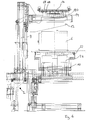
- the device 2 for introducing insulating materials in holes of perforated bricks 6, which represent a hole pattern, comprises a brick receptacle 10 supported on a frame 8.
- Various frame guides, motor drives, etc. are arranged on the frame 8, which are of secondary importance for the function of the device of interest here Significance so that a more detailed explanation and representation of these device parts is intended.
- FIG. 1 The basic position shown is shown above an alignment unit 12, the receiving device 14, which has various receiving elements 16.
- Clamping elements 18 are arranged on the receiving elements 16.
- the clamping elements 18 are designed here as metal sheets which are arranged to be movable towards and away from one another. Gripping elements are arranged on the clamping elements, which are designed as spring plates shaped like tweezers.
- the alignment unit 12 has alignment elements 20, which in the exemplary embodiment the clamping elements 18 are shown immediately adjacent. Both the alignment unit 12 and the receiving device 14 are guided movably up and down on the frame 8 by corresponding motor drives, the alignment unit 12 also being able to be moved relative to the receiving device 14. Both the alignment unit 12 and the receiving elements 16 are designed to widen upwards. Fixing elements 22 for fixing and aligning a perforated brick 12 are arranged on the brick holder 10. These are in Fig. 1 shown in a lowered position and can be raised to grip the brick 6. A suction box 24 is arranged below the brick holder 10. The pressure difference, in particular as a negative pressure in the holes of the perforated brick 12, is generated via this suction box.
- Fig. 2 the perforated brick 6 is shown in a raised and aligned position by the brick receptacle 10 and the fixing elements 22.
- the suction box 24 is also raised so that it rests against the underside of the perforated brick 6.
- Fig. 3 the strip-shaped insulating materials are shown in a position that has been brought into the receiving device 14 and alignment unit 12 by a feed device 28.
- the strip-shaped insulating materials 26 are shown threaded onto spiked grippers 30 of the feed device 28.
- Fig. 4 the alignment unit 12 is shown in a position lowered onto the surface of the perforated brick 6.
- the ends of the strip-shaped ones facing the perforated brick Insulating materials 26 are aligned with the holes 4 of the perforated brick 6 by the alignment elements 20 of the alignment unit 12.
- the clamping elements 18 of the receiving device 14 fix the strip-shaped insulating materials 26, so that the feed device 28 with the barbed grippers 30 can be separated from the strip-shaped insulating materials 26.
- the suction box 24 can be switched on in order to apply a pressure differential between the ends of the strip-shaped insulating materials 26.
- the receiving device is also lowered in the direction of the perforated brick 6 and shown in the lowest position. In this position, the gripping elements of the clamping elements 18 penetrate the holes in the perforated brick 6.
- the strip-shaped insulating materials 26 are now in the desired position within the holes 4 - In this position, the suction box 24 can be switched off and the clamping elements 18 opened in order to release the strip-shaped insulating materials 26.
- the receiving device 14, the aligning unit 12, the brick receiving element 10 and the suction box 24 then move back to the starting position as shown in FIG Fig. 1 is shown.
Landscapes
- Engineering & Computer Science (AREA)
- Structural Engineering (AREA)
- Chemical & Material Sciences (AREA)
- Ceramic Engineering (AREA)
- Mechanical Engineering (AREA)
- Furnace Housings, Linings, Walls, And Ceilings (AREA)
- Insulating Bodies (AREA)
- Devices For Post-Treatments, Processing, Supply, Discharge, And Other Processes (AREA)
Priority Applications (1)
| Application Number | Priority Date | Filing Date | Title |
|---|---|---|---|
| PL17000974T PL3266574T3 (pl) | 2016-07-04 | 2017-06-09 | Urządzenie i sposób wprowadzania materiałów izolacyjnych do cegły dziurawki |
Applications Claiming Priority (1)
| Application Number | Priority Date | Filing Date | Title |
|---|---|---|---|
| DE102016008020.5A DE102016008020B4 (de) | 2016-07-04 | 2016-07-04 | Vorrichtung und Verfahren zum Verbringen von Isoliermaterialien in Lochziegel |
Publications (2)
| Publication Number | Publication Date |
|---|---|
| EP3266574A1 EP3266574A1 (de) | 2018-01-10 |
| EP3266574B1 true EP3266574B1 (de) | 2021-02-24 |
Family
ID=59054941
Family Applications (1)
| Application Number | Title | Priority Date | Filing Date |
|---|---|---|---|
| EP17000974.0A Active EP3266574B1 (de) | 2016-07-04 | 2017-06-09 | Vorrichtung und verfahren zum verbringen von isoliermaterialien in lochziegel |
Country Status (5)
| Country | Link |
|---|---|
| EP (1) | EP3266574B1 (pl) |
| DE (1) | DE102016008020B4 (pl) |
| ES (1) | ES2869290T3 (pl) |
| PL (1) | PL3266574T3 (pl) |
| RU (1) | RU2707309C2 (pl) |
Families Citing this family (1)
| Publication number | Priority date | Publication date | Assignee | Title |
|---|---|---|---|---|
| CN111331718B (zh) * | 2020-04-24 | 2021-09-28 | 陶正云 | 一种陶瓷杯及其加工系统与加工方法 |
Family Cites Families (6)
| Publication number | Priority date | Publication date | Assignee | Title |
|---|---|---|---|---|
| GB461314A (en) * | 1935-08-06 | 1937-02-08 | Henry Warburton | Improvements in, and relating to, bricks |
| SE8004635L (sv) * | 1980-06-23 | 1981-12-24 | Ferila Lettblock Ab | Maskin for isolering av halblock |
| US5755216A (en) * | 1995-06-06 | 1998-05-26 | The University Of Dayton | Building products incorporating phase change materials and method of making same |
| DE202007009591U1 (de) * | 2007-07-09 | 2007-09-20 | Grenzebach Maschinenbau Gmbh | Vorrichtung zum Befüllen von Strukturen mit unterschiedlichen Hohlräumen |
| EP2180110A1 (en) * | 2008-10-21 | 2010-04-28 | Rockwool International A/S | Thermally insulated building brick |
| DE102010045927B4 (de) * | 2010-09-21 | 2012-12-20 | Keller Hcw Gmbh | Vorrichtung zum Einbringen von Isoliermaterialien in Lochziegel |
-
2016
- 2016-07-04 DE DE102016008020.5A patent/DE102016008020B4/de not_active Expired - Fee Related
-
2017
- 2017-06-09 ES ES17000974T patent/ES2869290T3/es active Active
- 2017-06-09 PL PL17000974T patent/PL3266574T3/pl unknown
- 2017-06-09 EP EP17000974.0A patent/EP3266574B1/de active Active
- 2017-07-03 RU RU2017123352A patent/RU2707309C2/ru active
Non-Patent Citations (1)
| Title |
|---|
| None * |
Also Published As
| Publication number | Publication date |
|---|---|
| EP3266574A1 (de) | 2018-01-10 |
| ES2869290T3 (es) | 2021-10-25 |
| DE102016008020B4 (de) | 2021-01-28 |
| RU2017123352A (ru) | 2019-01-09 |
| DE102016008020A1 (de) | 2018-01-04 |
| RU2707309C2 (ru) | 2019-11-26 |
| PL3266574T3 (pl) | 2021-09-27 |
| RU2017123352A3 (pl) | 2019-01-09 |
Similar Documents
| Publication | Publication Date | Title |
|---|---|---|
| EP2233626B1 (de) | Einführhilfe zur Bestückung von Nadelbrettern | |
| DE102016008020B4 (de) | Vorrichtung und Verfahren zum Verbringen von Isoliermaterialien in Lochziegel | |
| EP1147440A1 (de) | Vorrichtung zum trennen von mindestens einer lichtleitenden faser | |
| DE102010045927B4 (de) | Vorrichtung zum Einbringen von Isoliermaterialien in Lochziegel | |
| EP3075504B2 (de) | Vorrichtung zur herstellung von betonformteilen in einer formmaschine | |
| DE202008017576U1 (de) | Bearbeitungsmodul für eine Kabelabisoliervorrichtung | |
| DE3522076A1 (de) | Vorrichtung zum auswechseln der greiferbacken an manipulatoren | |
| EP2724832B1 (de) | Verfahren zur herstellung eines mauersteins mit dämmfüllung | |
| DE102013005176B4 (de) | Vorrichtung und Verfahren zur Herstellung von Bauteilen aus Faserverbundwerkstoffen | |
| DE2419998A1 (de) | Vorrichtung zum anbringen von entlastungsschnitten an vorgeritzten glasscheiben | |
| EP1995029B1 (de) | Verfahren zum Herstellen eines Formsteins und Formsteinfüllvorrichtung | |
| DE102008044352A1 (de) | Mobile Bohrvorrichtung zum Erstellen von Mehrfachbohrungen in einem Bauteil | |
| DE2653759A1 (de) | Verfahren und vorrichtung zum ausrichten von nutzen | |
| DE29515577U1 (de) | Mauerwerkstein / Bausatz | |
| AT514245B1 (de) | Farbkissenhalter sowie Vorrichtung und Verfahren zur Herstellung eines solchen | |
| DE202009001310U1 (de) | Fliesenschneidvorrichtung | |
| DE3807136A1 (de) | Verfahren zum sanieren von kaminen und vorrichtungen zum durchfuehren der einzelnen verfahrensschritte | |
| DE102018119196B4 (de) | Vorrichtung zum Durchführen einer Leitung durch eine Bodenplatte | |
| DE1511077B1 (de) | Vorrichtung zum Erfassen und Abfuehren des Stanzabfalles beim Bearbeiten von Werkstoffbahnen | |
| DE3329629A1 (de) | Verfahren und vorrichtung zum einsetzen eines stuetzringes in einen dauerelastischen dichtring, insbesondere fuer kunststoffrohre | |
| DE102016108880A1 (de) | Hybridsetter | |
| DE102006036193B4 (de) | Vorrichtung und Verfahren zur Montage eines Möbelkorpus | |
| DE1183966B (de) | Kabelbrett fuer die Herstellung von Kabelbaeumen fuer Fernmeldevermittlungsanlagen | |
| AT522423A1 (de) | Magazin für Einlegeteile | |
| EP2596931B1 (de) | Verfahren sowie formwerkzeug zur herstellung eines räumlichen flächengebildes |
Legal Events
| Date | Code | Title | Description |
|---|---|---|---|
| PUAI | Public reference made under article 153(3) epc to a published international application that has entered the european phase |
Free format text: ORIGINAL CODE: 0009012 |
|
| STAA | Information on the status of an ep patent application or granted ep patent |
Free format text: STATUS: THE APPLICATION HAS BEEN PUBLISHED |
|
| AK | Designated contracting states |
Kind code of ref document: A1 Designated state(s): AL AT BE BG CH CY CZ DE DK EE ES FI FR GB GR HR HU IE IS IT LI LT LU LV MC MK MT NL NO PL PT RO RS SE SI SK SM TR |
|
| AX | Request for extension of the european patent |
Extension state: BA ME |
|
| STAA | Information on the status of an ep patent application or granted ep patent |
Free format text: STATUS: REQUEST FOR EXAMINATION WAS MADE |
|
| 17P | Request for examination filed |
Effective date: 20180611 |
|
| RBV | Designated contracting states (corrected) |
Designated state(s): AL AT BE BG CH CY CZ DE DK EE ES FI FR GB GR HR HU IE IS IT LI LT LU LV MC MK MT NL NO PL PT RO RS SE SI SK SM TR |
|
| RAX | Requested extension states of the european patent have changed |
Extension state: ME Extension state: BA Payment date: 20180621 |
|
| RIC1 | Information provided on ipc code assigned before grant |
Ipc: B28B 11/04 20060101AFI20201013BHEP |
|
| GRAP | Despatch of communication of intention to grant a patent |
Free format text: ORIGINAL CODE: EPIDOSNIGR1 |
|
| STAA | Information on the status of an ep patent application or granted ep patent |
Free format text: STATUS: GRANT OF PATENT IS INTENDED |
|
| INTG | Intention to grant announced |
Effective date: 20201120 |
|
| GRAS | Grant fee paid |
Free format text: ORIGINAL CODE: EPIDOSNIGR3 |
|
| GRAA | (expected) grant |
Free format text: ORIGINAL CODE: 0009210 |
|
| STAA | Information on the status of an ep patent application or granted ep patent |
Free format text: STATUS: THE PATENT HAS BEEN GRANTED |
|
| AK | Designated contracting states |
Kind code of ref document: B1 Designated state(s): AL AT BE BG CH CY CZ DE DK EE ES FI FR GB GR HR HU IE IS IT LI LT LU LV MC MK MT NL NO PL PT RO RS SE SI SK SM TR |
|
| AX | Request for extension of the european patent |
Extension state: BA |
|
| REG | Reference to a national code |
Ref country code: CH Ref legal event code: EP |
|
| REG | Reference to a national code |
Ref country code: AT Ref legal event code: REF Ref document number: 1363880 Country of ref document: AT Kind code of ref document: T Effective date: 20210315 Ref country code: CH Ref legal event code: NV Representative=s name: KELLER SCHNEIDER PATENT- UND MARKENANWAELTE AG, CH |
|
| REG | Reference to a national code |
Ref country code: IE Ref legal event code: FG4D Free format text: LANGUAGE OF EP DOCUMENT: GERMAN |
|
| REG | Reference to a national code |
Ref country code: DE Ref legal event code: R096 Ref document number: 502017009425 Country of ref document: DE |
|
| REG | Reference to a national code |
Ref country code: NL Ref legal event code: FP |
|
| REG | Reference to a national code |
Ref country code: GR Ref legal event code: EP Ref document number: 20210400946 Country of ref document: GR Effective date: 20210519 |
|
| REG | Reference to a national code |
Ref country code: SK Ref legal event code: T3 Ref document number: E 36988 Country of ref document: SK |
|
| REG | Reference to a national code |
Ref country code: LT Ref legal event code: MG9D |
|
| PG25 | Lapsed in a contracting state [announced via postgrant information from national office to epo] |
Ref country code: FI Free format text: LAPSE BECAUSE OF FAILURE TO SUBMIT A TRANSLATION OF THE DESCRIPTION OR TO PAY THE FEE WITHIN THE PRESCRIBED TIME-LIMIT Effective date: 20210224 Ref country code: HR Free format text: LAPSE BECAUSE OF FAILURE TO SUBMIT A TRANSLATION OF THE DESCRIPTION OR TO PAY THE FEE WITHIN THE PRESCRIBED TIME-LIMIT Effective date: 20210224 Ref country code: PT Free format text: LAPSE BECAUSE OF FAILURE TO SUBMIT A TRANSLATION OF THE DESCRIPTION OR TO PAY THE FEE WITHIN THE PRESCRIBED TIME-LIMIT Effective date: 20210624 Ref country code: NO Free format text: LAPSE BECAUSE OF FAILURE TO SUBMIT A TRANSLATION OF THE DESCRIPTION OR TO PAY THE FEE WITHIN THE PRESCRIBED TIME-LIMIT Effective date: 20210524 Ref country code: BG Free format text: LAPSE BECAUSE OF FAILURE TO SUBMIT A TRANSLATION OF THE DESCRIPTION OR TO PAY THE FEE WITHIN THE PRESCRIBED TIME-LIMIT Effective date: 20210524 Ref country code: LT Free format text: LAPSE BECAUSE OF FAILURE TO SUBMIT A TRANSLATION OF THE DESCRIPTION OR TO PAY THE FEE WITHIN THE PRESCRIBED TIME-LIMIT Effective date: 20210224 |
|
| PG25 | Lapsed in a contracting state [announced via postgrant information from national office to epo] |
Ref country code: SE Free format text: LAPSE BECAUSE OF FAILURE TO SUBMIT A TRANSLATION OF THE DESCRIPTION OR TO PAY THE FEE WITHIN THE PRESCRIBED TIME-LIMIT Effective date: 20210224 Ref country code: RS Free format text: LAPSE BECAUSE OF FAILURE TO SUBMIT A TRANSLATION OF THE DESCRIPTION OR TO PAY THE FEE WITHIN THE PRESCRIBED TIME-LIMIT Effective date: 20210224 Ref country code: LV Free format text: LAPSE BECAUSE OF FAILURE TO SUBMIT A TRANSLATION OF THE DESCRIPTION OR TO PAY THE FEE WITHIN THE PRESCRIBED TIME-LIMIT Effective date: 20210224 |
|
| PG25 | Lapsed in a contracting state [announced via postgrant information from national office to epo] |
Ref country code: IS Free format text: LAPSE BECAUSE OF FAILURE TO SUBMIT A TRANSLATION OF THE DESCRIPTION OR TO PAY THE FEE WITHIN THE PRESCRIBED TIME-LIMIT Effective date: 20210624 |
|
| REG | Reference to a national code |
Ref country code: ES Ref legal event code: FG2A Ref document number: 2869290 Country of ref document: ES Kind code of ref document: T3 Effective date: 20211025 |
|
| PG25 | Lapsed in a contracting state [announced via postgrant information from national office to epo] |
Ref country code: SM Free format text: LAPSE BECAUSE OF FAILURE TO SUBMIT A TRANSLATION OF THE DESCRIPTION OR TO PAY THE FEE WITHIN THE PRESCRIBED TIME-LIMIT Effective date: 20210224 Ref country code: EE Free format text: LAPSE BECAUSE OF FAILURE TO SUBMIT A TRANSLATION OF THE DESCRIPTION OR TO PAY THE FEE WITHIN THE PRESCRIBED TIME-LIMIT Effective date: 20210224 |
|
| REG | Reference to a national code |
Ref country code: DE Ref legal event code: R097 Ref document number: 502017009425 Country of ref document: DE |
|
| PG25 | Lapsed in a contracting state [announced via postgrant information from national office to epo] |
Ref country code: DK Free format text: LAPSE BECAUSE OF FAILURE TO SUBMIT A TRANSLATION OF THE DESCRIPTION OR TO PAY THE FEE WITHIN THE PRESCRIBED TIME-LIMIT Effective date: 20210224 Ref country code: RO Free format text: LAPSE BECAUSE OF FAILURE TO SUBMIT A TRANSLATION OF THE DESCRIPTION OR TO PAY THE FEE WITHIN THE PRESCRIBED TIME-LIMIT Effective date: 20210224 |
|
| PLBE | No opposition filed within time limit |
Free format text: ORIGINAL CODE: 0009261 |
|
| STAA | Information on the status of an ep patent application or granted ep patent |
Free format text: STATUS: NO OPPOSITION FILED WITHIN TIME LIMIT |
|
| PG25 | Lapsed in a contracting state [announced via postgrant information from national office to epo] |
Ref country code: AL Free format text: LAPSE BECAUSE OF FAILURE TO SUBMIT A TRANSLATION OF THE DESCRIPTION OR TO PAY THE FEE WITHIN THE PRESCRIBED TIME-LIMIT Effective date: 20210224 Ref country code: MC Free format text: LAPSE BECAUSE OF FAILURE TO SUBMIT A TRANSLATION OF THE DESCRIPTION OR TO PAY THE FEE WITHIN THE PRESCRIBED TIME-LIMIT Effective date: 20210224 |
|
| 26N | No opposition filed |
Effective date: 20211125 |
|
| GBPC | Gb: european patent ceased through non-payment of renewal fee |
Effective date: 20210609 |
|
| PG25 | Lapsed in a contracting state [announced via postgrant information from national office to epo] |
Ref country code: SI Free format text: LAPSE BECAUSE OF FAILURE TO SUBMIT A TRANSLATION OF THE DESCRIPTION OR TO PAY THE FEE WITHIN THE PRESCRIBED TIME-LIMIT Effective date: 20210224 |
|
| PG25 | Lapsed in a contracting state [announced via postgrant information from national office to epo] |
Ref country code: LU Free format text: LAPSE BECAUSE OF NON-PAYMENT OF DUE FEES Effective date: 20210609 |
|
| PG25 | Lapsed in a contracting state [announced via postgrant information from national office to epo] |
Ref country code: GB Free format text: LAPSE BECAUSE OF NON-PAYMENT OF DUE FEES Effective date: 20210609 |
|
| PG25 | Lapsed in a contracting state [announced via postgrant information from national office to epo] |
Ref country code: IS Free format text: LAPSE BECAUSE OF FAILURE TO SUBMIT A TRANSLATION OF THE DESCRIPTION OR TO PAY THE FEE WITHIN THE PRESCRIBED TIME-LIMIT Effective date: 20210624 |
|
| PG25 | Lapsed in a contracting state [announced via postgrant information from national office to epo] |
Ref country code: IE Free format text: LAPSE BECAUSE OF NON-PAYMENT OF DUE FEES Effective date: 20220609 |
|
| PG25 | Lapsed in a contracting state [announced via postgrant information from national office to epo] |
Ref country code: HU Free format text: LAPSE BECAUSE OF FAILURE TO SUBMIT A TRANSLATION OF THE DESCRIPTION OR TO PAY THE FEE WITHIN THE PRESCRIBED TIME-LIMIT; INVALID AB INITIO Effective date: 20170609 |
|
| PG25 | Lapsed in a contracting state [announced via postgrant information from national office to epo] |
Ref country code: CY Free format text: LAPSE BECAUSE OF FAILURE TO SUBMIT A TRANSLATION OF THE DESCRIPTION OR TO PAY THE FEE WITHIN THE PRESCRIBED TIME-LIMIT Effective date: 20210224 |
|
| PG25 | Lapsed in a contracting state [announced via postgrant information from national office to epo] |
Ref country code: MK Free format text: LAPSE BECAUSE OF FAILURE TO SUBMIT A TRANSLATION OF THE DESCRIPTION OR TO PAY THE FEE WITHIN THE PRESCRIBED TIME-LIMIT Effective date: 20210224 |
|
| PG25 | Lapsed in a contracting state [announced via postgrant information from national office to epo] |
Ref country code: IE Free format text: LAPSE BECAUSE OF NON-PAYMENT OF DUE FEES Effective date: 20210609 |
|
| PGFP | Annual fee paid to national office [announced via postgrant information from national office to epo] |
Ref country code: DE Payment date: 20240318 Year of fee payment: 8 |
|
| PGFP | Annual fee paid to national office [announced via postgrant information from national office to epo] |
Ref country code: GR Payment date: 20240409 Year of fee payment: 8 |
|
| PGFP | Annual fee paid to national office [announced via postgrant information from national office to epo] |
Ref country code: NL Payment date: 20240628 Year of fee payment: 8 |
|
| PGFP | Annual fee paid to national office [announced via postgrant information from national office to epo] |
Ref country code: AT Payment date: 20240702 Year of fee payment: 8 Ref country code: CZ Payment date: 20240415 Year of fee payment: 8 |
|
| PGFP | Annual fee paid to national office [announced via postgrant information from national office to epo] |
Ref country code: SK Payment date: 20240415 Year of fee payment: 8 |
|
| PGFP | Annual fee paid to national office [announced via postgrant information from national office to epo] |
Ref country code: FR Payment date: 20240620 Year of fee payment: 8 |
|
| PGFP | Annual fee paid to national office [announced via postgrant information from national office to epo] |
Ref country code: PL Payment date: 20240410 Year of fee payment: 8 |
|
| PGFP | Annual fee paid to national office [announced via postgrant information from national office to epo] |
Ref country code: BE Payment date: 20240624 Year of fee payment: 8 |
|
| PG25 | Lapsed in a contracting state [announced via postgrant information from national office to epo] |
Ref country code: MT Free format text: LAPSE BECAUSE OF FAILURE TO SUBMIT A TRANSLATION OF THE DESCRIPTION OR TO PAY THE FEE WITHIN THE PRESCRIBED TIME-LIMIT Effective date: 20210224 |
|
| PGFP | Annual fee paid to national office [announced via postgrant information from national office to epo] |
Ref country code: IT Payment date: 20240605 Year of fee payment: 8 |
|
| PGFP | Annual fee paid to national office [announced via postgrant information from national office to epo] |
Ref country code: ES Payment date: 20240702 Year of fee payment: 8 Ref country code: CH Payment date: 20240701 Year of fee payment: 8 |
|
| PG25 | Lapsed in a contracting state [announced via postgrant information from national office to epo] |
Ref country code: TR Free format text: LAPSE BECAUSE OF FAILURE TO SUBMIT A TRANSLATION OF THE DESCRIPTION OR TO PAY THE FEE WITHIN THE PRESCRIBED TIME-LIMIT Effective date: 20210224 |
|
| REG | Reference to a national code |
Ref country code: DE Ref legal event code: R119 Ref document number: 502017009425 Country of ref document: DE |
|
| PG25 | Lapsed in a contracting state [announced via postgrant information from national office to epo] |
Ref country code: CZ Free format text: LAPSE BECAUSE OF NON-PAYMENT OF DUE FEES Effective date: 20250609 |
|
| REG | Reference to a national code |
Ref country code: CH Ref legal event code: H13 Free format text: ST27 STATUS EVENT CODE: U-0-0-H10-H13 (AS PROVIDED BY THE NATIONAL OFFICE) Effective date: 20260127 |
|
| REG | Reference to a national code |
Ref country code: SK Ref legal event code: MM4A Ref document number: E 36988 Country of ref document: SK Effective date: 20250609 |
|
| REG | Reference to a national code |
Ref country code: NL Ref legal event code: MM Effective date: 20250701 |
|
| REG | Reference to a national code |
Ref country code: AT Ref legal event code: MM01 Ref document number: 1363880 Country of ref document: AT Kind code of ref document: T Effective date: 20250609 |
|
| REG | Reference to a national code |
Ref country code: BE Ref legal event code: MM Effective date: 20250630 |
|
| PG25 | Lapsed in a contracting state [announced via postgrant information from national office to epo] |
Ref country code: NL Free format text: LAPSE BECAUSE OF NON-PAYMENT OF DUE FEES Effective date: 20250701 |
|
| PG25 | Lapsed in a contracting state [announced via postgrant information from national office to epo] |
Ref country code: DE Free format text: LAPSE BECAUSE OF NON-PAYMENT OF DUE FEES Effective date: 20260101 |
|
| PG25 | Lapsed in a contracting state [announced via postgrant information from national office to epo] |
Ref country code: AT Free format text: LAPSE BECAUSE OF NON-PAYMENT OF DUE FEES Effective date: 20250609 |
|
| PG25 | Lapsed in a contracting state [announced via postgrant information from national office to epo] |
Ref country code: BE Free format text: LAPSE BECAUSE OF NON-PAYMENT OF DUE FEES Effective date: 20250630 Ref country code: IT Free format text: LAPSE BECAUSE OF NON-PAYMENT OF DUE FEES Effective date: 20250609 |
|
| PG25 | Lapsed in a contracting state [announced via postgrant information from national office to epo] |
Ref country code: FR Free format text: LAPSE BECAUSE OF NON-PAYMENT OF DUE FEES Effective date: 20250630 |
|
| PG25 | Lapsed in a contracting state [announced via postgrant information from national office to epo] |
Ref country code: CH Free format text: LAPSE BECAUSE OF NON-PAYMENT OF DUE FEES Effective date: 20250630 |
|
| PG25 | Lapsed in a contracting state [announced via postgrant information from national office to epo] |
Ref country code: GR Free format text: LAPSE BECAUSE OF NON-PAYMENT OF DUE FEES Effective date: 20260108 |
|
| PG25 | Lapsed in a contracting state [announced via postgrant information from national office to epo] |
Ref country code: SK Free format text: LAPSE BECAUSE OF NON-PAYMENT OF DUE FEES Effective date: 20250609 |