EP3265666B1 - Anordnung zur zusätzlichen luftzuführung für einen motor - Google Patents
Anordnung zur zusätzlichen luftzuführung für einen motor Download PDFInfo
- Publication number
- EP3265666B1 EP3265666B1 EP16710564.2A EP16710564A EP3265666B1 EP 3265666 B1 EP3265666 B1 EP 3265666B1 EP 16710564 A EP16710564 A EP 16710564A EP 3265666 B1 EP3265666 B1 EP 3265666B1
- Authority
- EP
- European Patent Office
- Prior art keywords
- air
- engine
- throttle
- cylinder
- supplementary
- Prior art date
- Legal status (The legal status is an assumption and is not a legal conclusion. Google has not performed a legal analysis and makes no representation as to the accuracy of the status listed.)
- Active
Links
Images


Classifications
-
- F—MECHANICAL ENGINEERING; LIGHTING; HEATING; WEAPONS; BLASTING
- F02—COMBUSTION ENGINES; HOT-GAS OR COMBUSTION-PRODUCT ENGINE PLANTS
- F02M—SUPPLYING COMBUSTION ENGINES IN GENERAL WITH COMBUSTIBLE MIXTURES OR CONSTITUENTS THEREOF
- F02M35/00—Combustion-air cleaners, air intakes, intake silencers, or induction systems specially adapted for, or arranged on, internal-combustion engines
- F02M35/10—Air intakes; Induction systems
- F02M35/10006—Air intakes; Induction systems characterised by the position of elements of the air intake system in direction of the air intake flow, i.e. between ambient air inlet and supply to the combustion chamber
-
- F—MECHANICAL ENGINEERING; LIGHTING; HEATING; WEAPONS; BLASTING
- F02—COMBUSTION ENGINES; HOT-GAS OR COMBUSTION-PRODUCT ENGINE PLANTS
- F02B—INTERNAL-COMBUSTION PISTON ENGINES; COMBUSTION ENGINES IN GENERAL
- F02B27/00—Use of kinetic or wave energy of charge in induction systems, or of combustion residues in exhaust systems, for improving quantity of charge or for increasing removal of combustion residues
- F02B27/005—Oscillating pipes with charging achieved by arrangement, dimensions or shapes of intakes pipes or chambers; Ram air pipes
- F02B27/006—Oscillating pipes with charging achieved by arrangement, dimensions or shapes of intakes pipes or chambers; Ram air pipes of intake runners
-
- F—MECHANICAL ENGINEERING; LIGHTING; HEATING; WEAPONS; BLASTING
- F02—COMBUSTION ENGINES; HOT-GAS OR COMBUSTION-PRODUCT ENGINE PLANTS
- F02B—INTERNAL-COMBUSTION PISTON ENGINES; COMBUSTION ENGINES IN GENERAL
- F02B31/00—Modifying induction systems for imparting a rotation to the charge in the cylinder
- F02B31/08—Modifying induction systems for imparting a rotation to the charge in the cylinder having multiple air inlets
-
- F—MECHANICAL ENGINEERING; LIGHTING; HEATING; WEAPONS; BLASTING
- F02—COMBUSTION ENGINES; HOT-GAS OR COMBUSTION-PRODUCT ENGINE PLANTS
- F02D—CONTROLLING COMBUSTION ENGINES
- F02D9/00—Controlling engines by throttling air or fuel-and-air induction conduits or exhaust conduits
- F02D9/02—Controlling engines by throttling air or fuel-and-air induction conduits or exhaust conduits concerning induction conduits
-
- F—MECHANICAL ENGINEERING; LIGHTING; HEATING; WEAPONS; BLASTING
- F02—COMBUSTION ENGINES; HOT-GAS OR COMBUSTION-PRODUCT ENGINE PLANTS
- F02D—CONTROLLING COMBUSTION ENGINES
- F02D9/00—Controlling engines by throttling air or fuel-and-air induction conduits or exhaust conduits
- F02D9/08—Throttle valves specially adapted therefor; Arrangements of such valves in conduits
- F02D9/10—Throttle valves specially adapted therefor; Arrangements of such valves in conduits having pivotally-mounted flaps
- F02D9/1035—Details of the valve housing
- F02D9/1055—Details of the valve housing having a fluid by-pass
-
- F—MECHANICAL ENGINEERING; LIGHTING; HEATING; WEAPONS; BLASTING
- F02—COMBUSTION ENGINES; HOT-GAS OR COMBUSTION-PRODUCT ENGINE PLANTS
- F02D—CONTROLLING COMBUSTION ENGINES
- F02D9/00—Controlling engines by throttling air or fuel-and-air induction conduits or exhaust conduits
- F02D9/08—Throttle valves specially adapted therefor; Arrangements of such valves in conduits
- F02D9/10—Throttle valves specially adapted therefor; Arrangements of such valves in conduits having pivotally-mounted flaps
- F02D9/109—Throttle valves specially adapted therefor; Arrangements of such valves in conduits having pivotally-mounted flaps having two or more flaps
-
- F—MECHANICAL ENGINEERING; LIGHTING; HEATING; WEAPONS; BLASTING
- F02—COMBUSTION ENGINES; HOT-GAS OR COMBUSTION-PRODUCT ENGINE PLANTS
- F02M—SUPPLYING COMBUSTION ENGINES IN GENERAL WITH COMBUSTIBLE MIXTURES OR CONSTITUENTS THEREOF
- F02M35/00—Combustion-air cleaners, air intakes, intake silencers, or induction systems specially adapted for, or arranged on, internal-combustion engines
- F02M35/10—Air intakes; Induction systems
- F02M35/10006—Air intakes; Induction systems characterised by the position of elements of the air intake system in direction of the air intake flow, i.e. between ambient air inlet and supply to the combustion chamber
- F02M35/10072—Intake runners
-
- F—MECHANICAL ENGINEERING; LIGHTING; HEATING; WEAPONS; BLASTING
- F02—COMBUSTION ENGINES; HOT-GAS OR COMBUSTION-PRODUCT ENGINE PLANTS
- F02M—SUPPLYING COMBUSTION ENGINES IN GENERAL WITH COMBUSTIBLE MIXTURES OR CONSTITUENTS THEREOF
- F02M35/00—Combustion-air cleaners, air intakes, intake silencers, or induction systems specially adapted for, or arranged on, internal-combustion engines
- F02M35/10—Air intakes; Induction systems
- F02M35/10091—Air intakes; Induction systems characterised by details of intake ducts: shapes; connections; arrangements
- F02M35/10131—Ducts situated in more than one plane; Ducts of one plane crossing ducts of another plane
-
- F—MECHANICAL ENGINEERING; LIGHTING; HEATING; WEAPONS; BLASTING
- F02—COMBUSTION ENGINES; HOT-GAS OR COMBUSTION-PRODUCT ENGINE PLANTS
- F02M—SUPPLYING COMBUSTION ENGINES IN GENERAL WITH COMBUSTIBLE MIXTURES OR CONSTITUENTS THEREOF
- F02M35/00—Combustion-air cleaners, air intakes, intake silencers, or induction systems specially adapted for, or arranged on, internal-combustion engines
- F02M35/10—Air intakes; Induction systems
- F02M35/10242—Devices or means connected to or integrated into air intakes; Air intakes combined with other engine or vehicle parts
- F02M35/10255—Arrangements of valves; Multi-way valves
-
- F—MECHANICAL ENGINEERING; LIGHTING; HEATING; WEAPONS; BLASTING
- F02—COMBUSTION ENGINES; HOT-GAS OR COMBUSTION-PRODUCT ENGINE PLANTS
- F02M—SUPPLYING COMBUSTION ENGINES IN GENERAL WITH COMBUSTIBLE MIXTURES OR CONSTITUENTS THEREOF
- F02M35/00—Combustion-air cleaners, air intakes, intake silencers, or induction systems specially adapted for, or arranged on, internal-combustion engines
- F02M35/10—Air intakes; Induction systems
- F02M35/10242—Devices or means connected to or integrated into air intakes; Air intakes combined with other engine or vehicle parts
- F02M35/10275—Means to avoid a change in direction of incoming fluid, e.g. all intake ducts diverging from plenum chamber at acute angles; Check valves; Flame arrestors for backfire prevention
-
- F—MECHANICAL ENGINEERING; LIGHTING; HEATING; WEAPONS; BLASTING
- F02—COMBUSTION ENGINES; HOT-GAS OR COMBUSTION-PRODUCT ENGINE PLANTS
- F02M—SUPPLYING COMBUSTION ENGINES IN GENERAL WITH COMBUSTIBLE MIXTURES OR CONSTITUENTS THEREOF
- F02M35/00—Combustion-air cleaners, air intakes, intake silencers, or induction systems specially adapted for, or arranged on, internal-combustion engines
- F02M35/10—Air intakes; Induction systems
- F02M35/10242—Devices or means connected to or integrated into air intakes; Air intakes combined with other engine or vehicle parts
- F02M35/10308—Equalizing conduits, e.g. between intake ducts or between plenum chambers
-
- F—MECHANICAL ENGINEERING; LIGHTING; HEATING; WEAPONS; BLASTING
- F02—COMBUSTION ENGINES; HOT-GAS OR COMBUSTION-PRODUCT ENGINE PLANTS
- F02M—SUPPLYING COMBUSTION ENGINES IN GENERAL WITH COMBUSTIBLE MIXTURES OR CONSTITUENTS THEREOF
- F02M35/00—Combustion-air cleaners, air intakes, intake silencers, or induction systems specially adapted for, or arranged on, internal-combustion engines
- F02M35/10—Air intakes; Induction systems
- F02M35/104—Intake manifolds
- F02M35/1045—Intake manifolds characterised by the charge distribution between the cylinders/combustion chambers or its homogenisation
-
- F—MECHANICAL ENGINEERING; LIGHTING; HEATING; WEAPONS; BLASTING
- F02—COMBUSTION ENGINES; HOT-GAS OR COMBUSTION-PRODUCT ENGINE PLANTS
- F02B—INTERNAL-COMBUSTION PISTON ENGINES; COMBUSTION ENGINES IN GENERAL
- F02B31/00—Modifying induction systems for imparting a rotation to the charge in the cylinder
- F02B31/08—Modifying induction systems for imparting a rotation to the charge in the cylinder having multiple air inlets
- F02B31/085—Modifying induction systems for imparting a rotation to the charge in the cylinder having multiple air inlets having two inlet valves
-
- F—MECHANICAL ENGINEERING; LIGHTING; HEATING; WEAPONS; BLASTING
- F02—COMBUSTION ENGINES; HOT-GAS OR COMBUSTION-PRODUCT ENGINE PLANTS
- F02D—CONTROLLING COMBUSTION ENGINES
- F02D9/00—Controlling engines by throttling air or fuel-and-air induction conduits or exhaust conduits
- F02D9/02—Controlling engines by throttling air or fuel-and-air induction conduits or exhaust conduits concerning induction conduits
- F02D2009/0201—Arrangements; Control features; Details thereof
- F02D2009/0213—Electronic or electric governor
-
- F—MECHANICAL ENGINEERING; LIGHTING; HEATING; WEAPONS; BLASTING
- F02—COMBUSTION ENGINES; HOT-GAS OR COMBUSTION-PRODUCT ENGINE PLANTS
- F02M—SUPPLYING COMBUSTION ENGINES IN GENERAL WITH COMBUSTIBLE MIXTURES OR CONSTITUENTS THEREOF
- F02M35/00—Combustion-air cleaners, air intakes, intake silencers, or induction systems specially adapted for, or arranged on, internal-combustion engines
- F02M35/10—Air intakes; Induction systems
- F02M35/104—Intake manifolds
- F02M35/108—Intake manifolds with primary and secondary intake passages
- F02M35/1085—Intake manifolds with primary and secondary intake passages the combustion chamber having multiple intake valves
-
- F—MECHANICAL ENGINEERING; LIGHTING; HEATING; WEAPONS; BLASTING
- F02—COMBUSTION ENGINES; HOT-GAS OR COMBUSTION-PRODUCT ENGINE PLANTS
- F02M—SUPPLYING COMBUSTION ENGINES IN GENERAL WITH COMBUSTIBLE MIXTURES OR CONSTITUENTS THEREOF
- F02M35/00—Combustion-air cleaners, air intakes, intake silencers, or induction systems specially adapted for, or arranged on, internal-combustion engines
- F02M35/10—Air intakes; Induction systems
- F02M35/104—Intake manifolds
- F02M35/116—Intake manifolds for engines with cylinders in V-arrangement or arranged oppositely relative to the main shaft
-
- Y—GENERAL TAGGING OF NEW TECHNOLOGICAL DEVELOPMENTS; GENERAL TAGGING OF CROSS-SECTIONAL TECHNOLOGIES SPANNING OVER SEVERAL SECTIONS OF THE IPC; TECHNICAL SUBJECTS COVERED BY FORMER USPC CROSS-REFERENCE ART COLLECTIONS [XRACs] AND DIGESTS
- Y02—TECHNOLOGIES OR APPLICATIONS FOR MITIGATION OR ADAPTATION AGAINST CLIMATE CHANGE
- Y02T—CLIMATE CHANGE MITIGATION TECHNOLOGIES RELATED TO TRANSPORTATION
- Y02T10/00—Road transport of goods or passengers
- Y02T10/10—Internal combustion engine [ICE] based vehicles
- Y02T10/12—Improving ICE efficiencies
Definitions
- the present disclosure relates to a throttling mechanism for an engine and, more particularly, to a supplementary air throttling feature for supplying air to a supplementary intake air circuit of an internal combustion engine.
- faster combustion burn rates may be achieved by increasing turbulence in the combustion air entering the combustion chamber.
- By increasing the turbulence of the combustion air better fuel-air mixing may occur.
- an internal combustion engine 1000 includes at least one cylinder 60 with a combustion chamber 100 therein, an air inlet 120, and at least one intake port 140.
- a throttle body assembly 200 has a body portion 240 and a throttle plate 260, and a supplementary air assembly 400 includes a supplementary air inlet or port 420 and an air tube 440 for introducing a swirl into the combustion air to increase turbulence when engine 1000 is operating at low load or idle conditions.
- An idle air control valve 500 may also be provided to control throttle at supplementary air inlet 420. More particularly, in some embodiments, a flow of air travels through air tube 440 and air inlet 420 and into the intake port 140 of engine 1000.
- An engine control unit may be electrically coupled to idle air control valve 500 to control idle air control valve 500 based on predetermined parameters and/or conditions of engine 1000 during operation.
- JPS54103913 discloses an internal combustion engine comprising a cylinder defining an internal combustion chamber and an air intake system comprising an air inlet and an intake port of the cylinder.
- the engine also comprises a supplementary fluid inlet coupled to the intake port.
- US2008/053391 generally relates to an air-intake apparatus for an internal combustion engine.
- DE29811432 U1 generally relates to a pipe system, in particular an intake manifold system for an internal combustion engine.
- JPH0216329 generally relates to an international combustion engine comprising an air inlet coupled to a throttle valve and a supplementary fluid inlet coupled to the intake port of a cylinder.
- an internal combustion engine including a crankcase including a crankshaft and at least one cylinder coupled to the crankcase.
- the at least one cylinder has an intake port and defines an internal combustion chamber.
- the engine further includes a throttle body assembly with a throttle valve coupled to an air inlet of the at least one cylinder and a throttle plate.
- the engine includes a supplementary air inlet fluidly coupled to the intake port and spaced apart from the throttle valve.
- the supplementary air inlet is configured to receive a flow of air from a location downstream of the throttle plate when the throttle plate is in a fully closed position and the flow of air is directed into the combustion chamber through the intake port for combustion therein.
- an internal combustion engine comprising a crankcase including a crankshaft; at least one cylinder coupled to the crankcase and having an intake port and the at least one cylinder defining an internal combustion chamber; a throttle body assembly having a throttle valve coupled to an air inlet of the at least one cylinder and including a throttle plate; a supplementary air inlet fluidly coupled to the intake port, wherein the supplementary air inlet is configured to receive a flow of air from a location downstream of the throttle plate of the at least one cylinder, and the flow of air is directed into the intake port of the at least one cylinder for combustion within the combustion chamber.
- an internal combustion engine including a crankcase including a crankshaft and at least one cylinder coupled to the crankcase.
- the at least one cylinder defines an internal combustion chamber.
- the engine further includes a throttle body assembly with an inlet and an outlet fluidly coupled to an air inlet of the at least one cylinder.
- the throttle body assembly also includes a body portion and a throttle plate movably coupled within the body portion.
- the body portion includes a plurality of apertures.
- the engine also includes a supplementary air inlet fluidly coupled to the intake port and configured to receive air through at least one of the plurality of apertures of the body portion of the throttle body.
- a throttle body assembly for use with an engine including a throttle port configured to fluidly couple with an air intake of the engine and has a body portion including a plurality of apertures.
- the throttle body assembly also includes a throttle plate movably coupled within the body portion and an outlet port coupled to the body portion and positioned adjacent the plurality of apertures.
- Engine 2 includes a crankcase 4 and at least one cylinder 6.
- engine 2 includes two cylinders 6 in a V-shaped configuration; however, engine 2 may include any number of cylinder(s) 6 in any configuration possible for cylinder 6.
- Each cylinder 6 includes a cylinder head 8 defining a top end of each cylinder 6.
- An internal combustion chamber 10 ( Fig. 4A ) is defined within each cylinder 6 and is configured for combustion therein during operation of engine 2.
- each cylinder 6 also includes an air inlet 12 for supplying air to combustion chamber 10 for combustion.
- Engine 2 also includes at least one intake port 14 and an exhaust port (not shown). Air inlet 12 and intake port 14 facilitate combustion with combustion chamber 10.
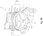
- a throttle body assembly 20 is coupled to engine 2 which includes a plurality of throttle valves 22 which are each fluidly coupled to the air inlet 12 of each cylinder 6.
- Throttle valve 22 includes a body portion 24 and a throttle plate 26 movably coupled within body portion 24.
- Body portion 24 includes a top wall 24a, a bottom wall 24b, a first side wall 24c, and a second side wall 24d.
- Illustrative throttle body assembly 20 may be electronically controlled by an engine control unit (“ECU") 30 to control operation of throttle body assembly 20, including movement of throttle plate 26.
- throttle plate 26 is configured to rotatably move between at least positions A, B, C, D, and any position therebetween ( Fig. 6 ).
- throttle body assembly 20 also includes an outlet 28 coupled to body portion 24, as shown in Figs. 4A-6 .
- body portion 24 of throttle body assembly 20 includes a plurality of apertures 32 which are arranged in a staggered orientation.
- apertures 32 extend through bottom wall 24b of body portion 24, however, apertures 32 may extend through any of walls 24a, 24b, 24c, 24d.
- at least one aperture 32a is positioned downstream of throttle plate 26 and at least one aperture 32b is positioned upstream of throttle plate 26 when throttle plate 26 is in a fully closed position A ( Fig. 6 ).
- Fig. 6 the embodiment of Fig.
- each aperture 32 is positioned downstream of throttle plate 26 when throttle plate 26 is in the fully closed position A ( Fig. 6 ).
- Outlet 28 is positioned adjacent apertures 32 such that when a portion of air at air inlet 12 of engine 2 is received through apertures 32, that portion of air flows into outlet 28.
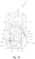
- an auxiliary or supplementary air circuit or assembly 40 is fluidly coupled to throttle body assembly 20 and intake port 14 of engine 2.
- Supplementary air assembly 40 includes a supplementary air inlet 42 and a supplementary air tube or hose 44.
- Supplementary air inlet 42 is fluidly coupled to cylinder 6 of engine 2 and, more particularly, is fluidly coupled to intake port 14 to provide air to combustion chamber 10 via intake port 14 for combustion at low load, idle conditions, or at other operating conditions of engine 2. More particularly, when engine 2 operates at low load or idle, throttle plate 26 may be nearly closed (e.g., throttle plate 26 may be positioned in a first intermediate position B ( Fig. 6 )) because there is no input to the throttle. However, air is still needed within combustion chamber 10 to maintain operation of engine 2 even at idle, low load, or other conditions of engine 2.
- illustrative supplementary air tube 44 has a first end 44a coupled to supplementary air inlet 42 and a second end 44b coupled to outlet 28.
- supplementary air tube 44 is positioned within an outer sleeve 46.
- Supplementary air tube 44 is configured to receive a flow of air at air inlet 12 which flows through supplementary air inlet 42, into intake port 14, and then into the combustion chamber 10 for combustion therein. When the air flows through supplementary air tube 44 and into supplementary air inlet 42, the turbulence of the air increases, which may increase the combustion rate within combustion chamber 10.
- throttle valve 22 in operation, when engine 2 is not operating, throttle valve 22 is closed and throttle plate 26 is positioned in the fully closed position A.
- throttle plate 26 when in the fully closed position A, throttle plate 26 extends between top and bottom walls 24a, 24b of body portion 24, and may be in contact with or sealed against walls 24, to block air flow into air inlet 12.
- air flow is not received within combustion chamber 10 or through apertures 32, which are positioned downstream of throttle plate 26 in the fully closed position A, such that the position and movement of throttle plate 26 controls the air flow to apertures 32.
- ECU 30 electronically controls operation of throttle body assembly 20 based on throttle conditions of engine 2 and/or other operating parameters of engine 2. For example, when a large throttle input occurs, ECU 30 transmits a signal to throttle body assembly 20 and throttle plate 26 is moved to the fully open position D. When throttle plate 26 is in the fully open position D, air flows through throttle valve 22, into air inlet 12, and into combustion chamber 10 for combustion therein. In the open positioned, throttle plate 26 is generally parallel to top and bottom walls 24a, 24b and extends in the same direction as the flow path of air into combustion chamber 10.
- ECU 30 transmits a signal to throttle body assembly 20 and throttle plate 26 may be opened to a first intermediate position B, a second intermediate position C, or any position between fully closed position A and fully open position D.
- throttle plate 26 may be opened to a first intermediate position B, a second intermediate position C, or any position between fully closed position A and fully open position D.
- throttle plate 26 when throttle plate 26 is at least partially opened, at least one aperture 32 is now upstream of throttle plate 26 and is exposed and a portion of air in throttle valve 22 flows through the exposed aperture(s) 32.
- the position of throttle plate 26 affects which apertures 32 receive air and/or the quantity of air received through apertures 32 such that the position of throttle plate 26 modulates and controls air flow through supplementary air assembly 40.
- a one-way valve 48 ( Fig. 4A ), for example a reed valve, is positioned adjacent apertures 32 to control the direction of air flow within supplementary air tube 44. More particularly, one-way valve 48 allows the flow of air in one direction toward supplementary air tube 44 but inhibits air flow in the opposite direction toward throttle valve 22.
- Figs. 4A-6 do not require the use of an air control valve 500 ( Fig. 3 ) because operation of supplementary air assembly 40 is controlled by throttle body assembly 20 of engine 2. As such, no additional valve or throttling mechanism is required to control the supplementary air entering intake port 14 and combustion chamber 10 because supplementary air assembly 40 is controlled and modulated by throttle body assembly 20.
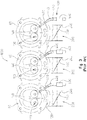
- an illustrative engine 2' includes three cylinders 6 1, 6 2 , 6 3 , however, engine 2' may include any number of cylinders.
- An alternative embodiment of throttle body assembly 20 is also shown as throttle body assembly 20' which is fluidly coupled to cylinders 6 1, 6 2 , 6 3 .
- Throttle body assembly 20' includes a throttle valve 22' fluidly coupled to air inlet 12 of each cylinder 6 1, 6 2 , 6 3 .
- Throttle valve 22' has a solid body portion 24' such that body portion 24' of throttle body assembly 20' does not include apertures 32.
- Throttle body assembly 20' is fluidly coupled to a supplementary air assembly 40' which includes supplementary air inlet 42 fluidly coupled to intake port 14 and supplementary air tubes 44 1 ', 44 2 ', 44 3 ' corresponding to cylinders 6 1, 6 2 , 6 3 , respectively. More particularly, supplementary air tube 44 1 ' has a first end 44a 1 ' coupled to supplementary air inlet 42 of cylinder 6 1 and a second end 44b 1 ' which extends into body portion 24' of cylinder 6 3 and is downstream of throttle plate 26.
- supplementary air tube 44 2 ' has a first end 44a 2 ' coupled to supplementary air inlet 42 of cylinder 6 2 and a second end 44b 2 ' which extends into body portion 24' of cylinder 6 1 and is downstream of throttle plate 26.
- Supplementary air tube 44 3 ' has a first end 44a 3 ' coupled to supplementary air inlet 42 of cylinder 6 3 and a second end 44b 3 ' which extends into body portion 24' of cylinder 6 2 and is downstream of throttle plate 26.
- cylinder 6 1, 6 2 , 6 3 are fluidly coupled to each other through supplementary air assembly 40'.
- a one-way valve 48 such as a reed valve, is positioned within any of supplementary air tubes 44 1 ', 44 2 ', 44 3 ' to control the direction of air flow therein.
- the combustion cycles of cylinders 6 1, 6 2 , 6 3 are out of phase with each other such that when one of cylinders 6 1, 6 2 , 6 3 is in one stroke of the combustion cycle (e.g., the power stroke), the other cylinders 6 1, 6 2 , 6 3 are in a different stroke (e.g., intake stroke, exhaust stroke, etc.). Because cylinders 6 1, 6 2 , 6 3 are out of phase with each other, there is a pressure difference between intake ports of cylinders 6 1, 6 2 , 6 3 , which facilitates air flow between the intake ports of cylinders 6 1, 6 2 , 6 3 through supplementary air assembly 40'.
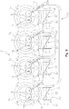
- an illustrative engine 2' includes four cylinders 6 1, 6 2 , 6 3 , 6 4 , but may include any number of cylinders.
- Throttle body assembly 20' is fluidly coupled to cylinders 6 1, 6 2 , 6 3 , 6 4 .
- Throttle body assembly 20' includes throttle valve 22' with the solid body portion 24' such that body portion 24' of throttle body assembly 20' does not include apertures 32.
- Supplementary air assembly 40 is fluidly coupled to throttle body assembly 20'.
- Supplementary air assembly 40" includes a first supplementary air tube 52 which has a first end 52a fluidly coupled to supplementary air inlet 42 of cylinder 6 1 and a second end fluidly coupled to supplementary air inlet 42 of cylinder 6 4 .
- supplementary air assembly 40" includes a second supplementary air tube 54 which has a first end 54a fluidly coupled to supplementary air inlet 42 of cylinder 6 2 and a second end 54b fluidly coupled to supplementary air inlet 42 of cylinder 6 3 .
- the combustion cycles of cylinders 6 1 , 6 2 , 6 3 , 6 4 are out of phase with each other such that when one of cylinders 6 1 , 6 2 , 6 3 , 6 4 is in one stroke of the combustion cycle (e.g., the power stroke), the other cylinders 6 1 , 6 2 , 6 3 , 6 4 are in a different stroke (e.g., intake stroke, exhaust stroke, etc.).
- one stroke of the combustion cycle e.g., the power stroke
- the other cylinders 6 1 , 6 2 , 6 3 , 6 4 are in a different stroke (e.g., intake stroke, exhaust stroke, etc.).
- cylinders 6 1 , 6 2 , 6 3 , 6 4 are out of phase with each other, there is a pressure difference between the intake port of cylinders 6 1 , 6 2 , 6 3 , 6 4 , which facilitates air flow between the intake port of cylinders 6 1 , 6 2 , 6 3 , 6 4 through supplementary air assembly 40".
- supplementary air assembly 40 For example, when pressure is high in the intake port of cylinder 6 1 , the pressure in the intake port of cylinder 6 4 is low which facilitates air flow through supplementary air tube 52 and into supplementary air inlet 42 of cylinder 6 4 .
Landscapes
- Engineering & Computer Science (AREA)
- Chemical & Material Sciences (AREA)
- Combustion & Propulsion (AREA)
- Mechanical Engineering (AREA)
- General Engineering & Computer Science (AREA)
- Control Of Throttle Valves Provided In The Intake System Or In The Exhaust System (AREA)
Claims (6)
- Verbrennungsmotor (2), der ein Kurbelgehäuse (4) umfasst und Folgendes beinhaltet
eine Kurbelwelle;
mindestens einen Zylinder (6; 6i, 62, 63, 64), der an das Kurbelgehäuse gekoppelt ist und eine interne Brennkammer (10) definiert;
ein Luftansaugsystem, das einen Lufteinlass (12) und einen Ansauganschluss (14) des mindestens einen Zylinders, einen Zusatzlufteinlass (42), der fluidisch an den Ansauganschluss gekoppelt ist, und eine Drosselgehäuseanordnung (20) mit einem Drosselventil (22), das an den Lufteinlass gekoppelt ist und eine Drosselklappe (26) beinhaltet, umfasst;
wobei der Zusatzlufteinlass dazu ausgelegt ist, einen Luftstrom vom Luftansaugsystem des mindestens einen Zylinders von einer Stelle stromabwärts von der Drosselklappe zu empfangen, der Luftstrom in den Ansauganschluss des mindestens einen Zylinders zur Verbrennung in der Brennkammer geleitet wird und der Luftstrom durch die Position der Drosselklappe gesteuert und moduliert wird;
dadurch gekennzeichnet, dass die Drosselgehäuseanordnung eine Vielzahl von Öffnungen beinhaltet, die sich durch eine Wand der Drosselgehäuseanordnung erstrecken; und dadurch, dass ein Abschnitt der Vielzahl von Öffnungen stromabwärts von der Drosselklappe positioniert ist, wenn sich die Drosselklappe in der vollständig geschlossenen Position befindet, und ein Abschnitt der Öffnungen dazu ausgelegt ist, Luft zu empfangen, wenn sich die Drosselklappe in der vollständig geschlossenen Position (A) befindet, und jede der Öffnungen Luft empfängt, wenn sich die Drosselklappe in einer geöffneten Position (B, C, D) befindet;
und dadurch, dass die Vielzahl von Öffnungen mindestens ein Einwegeventil (48) beinhalten, um den Luftstrom zum Zusatzlufteinlass zu erlauben, den Luftstrom in die entgegengesetzte Richtung zum Drosselventil aber zu unterbinden. - Motor nach Anspruch 1, dadurch gekennzeichnet, dass der Luftstrom durch ein Zusatzluftrohr (44; 441', 442', 443', 52, 54) mit einem ersten und einem zweiten Ende (44a, 44b; 44a1', 44b1'; 44a2', 44b2' ; 44a3', 44b3'; 52a, 52b; 54a, 54b) empfangen wird.
- Motor nach Anspruch 2, dadurch gekennzeichnet, dass das erste Ende des Zusatzluftrohrs (44a, 44a1'; 44a2' , 44a3' ) positioniert ist, um einen Luftstrom in den Ansauganschluss zu leiten, und ein zweites Ende (44b, 44b1' , 44b2' , 44b3') dem Drosselventil benachbart positioniert ist.
- Motor nach einem der Ansprüche 1 bis 3, dadurch gekennzeichnet, dass das Zusatzluftrohr an einem einzelnen Zylinder positioniert ist.
- Motor nach einem der Ansprüche 1 bis 4, dadurch gekennzeichnet, dass der Betrieb der Drosselgehäuseanordnung von einer Motorsteuereinheit elektronisch gesteuert wird.
- Motor nach einem der Ansprüche 1 bis 5, dadurch gekennzeichnet, dass der Luftstrom, der in den Ansauganschluss des mindestens einen Zylinders zur Verbrennung in der Brennkammer geleitet wird, von der Drosselklappe moduliert wird, ohne dass ein zusätzliches Ventil oder ein zusätzlicher Drosselmechanismus erforderlich ist.
Applications Claiming Priority (2)
| Application Number | Priority Date | Filing Date | Title |
|---|---|---|---|
| US201562129183P | 2015-03-06 | 2015-03-06 | |
| PCT/US2016/020357 WO2016144630A1 (en) | 2015-03-06 | 2016-03-02 | Supplementary air assembly for an engine |
Publications (2)
| Publication Number | Publication Date |
|---|---|
| EP3265666A1 EP3265666A1 (de) | 2018-01-10 |
| EP3265666B1 true EP3265666B1 (de) | 2021-04-28 |
Family
ID=55543085
Family Applications (1)
| Application Number | Title | Priority Date | Filing Date |
|---|---|---|---|
| EP16710564.2A Active EP3265666B1 (de) | 2015-03-06 | 2016-03-02 | Anordnung zur zusätzlichen luftzuführung für einen motor |
Country Status (8)
| Country | Link |
|---|---|
| US (1) | US10247148B2 (de) |
| EP (1) | EP3265666B1 (de) |
| JP (1) | JP6779222B2 (de) |
| CN (1) | CN107429641B (de) |
| AU (1) | AU2016229289B2 (de) |
| BR (1) | BR112017018762A2 (de) |
| CA (1) | CA2978309A1 (de) |
| WO (1) | WO2016144630A1 (de) |
Family Cites Families (36)
| Publication number | Priority date | Publication date | Assignee | Title |
|---|---|---|---|---|
| GB1195060A (en) * | 1966-10-05 | 1970-06-17 | Vergaser Ges M B H & Co K G De | Improvements in Induction Systems for Internal Combustion Engines. |
| US3437320A (en) * | 1966-11-10 | 1969-04-08 | Brooks Walker | Carburetor |
| DE2033624C2 (de) * | 1969-07-15 | 1982-12-16 | Alfa Romeo S.p.A., Milano | Vorrichtung zur Handeinstellung der Leerlaufdrehzahl eines Verbrennungsmotors |
| JPS5624784B2 (de) * | 1973-07-24 | 1981-06-08 | ||
| US4867109A (en) * | 1976-11-26 | 1989-09-19 | Etsuhiro Tezuka | Intake passage arrangement for internal combustion engines |
| JPS6035533B2 (ja) * | 1977-09-09 | 1985-08-15 | ヤマハ発動機株式会社 | エンジンの吸気装置 |
| JPS54103913A (en) * | 1978-02-01 | 1979-08-15 | Fuji Heavy Ind Ltd | Internal combustion engine |
| JPS54118915A (en) * | 1978-03-07 | 1979-09-14 | Toyota Motor Corp | Suction controller for internal combustion engine |
| JPS6060007B2 (ja) * | 1978-05-22 | 1985-12-27 | トヨタ自動車株式会社 | カウンタフロ−型多気筒内燃機関の吸気装置 |
| JPS589249B2 (ja) * | 1978-08-10 | 1983-02-19 | トヨタ自動車株式会社 | 多気筒内燃機関の吸気装置 |
| JPS5583528U (de) * | 1978-12-04 | 1980-06-09 | ||
| JPS5583528A (en) | 1978-12-18 | 1980-06-24 | Inoue Japax Res Inc | Wire cut electrical discharge machining device |
| JPS5627025A (en) * | 1979-08-10 | 1981-03-16 | Honda Motor Co Ltd | Suction device in internal-combustion engine |
| JPS5783631A (en) * | 1980-11-13 | 1982-05-25 | Suzuki Motor Co Ltd | Internal combustion engine |
| US4516544A (en) * | 1982-05-25 | 1985-05-14 | Toyota Jidosha Kabushiki Kaisha | Helically-shaped intake port of an internal-combustion engine |
| JPS6134317A (ja) * | 1984-07-26 | 1986-02-18 | Suzuki Motor Co Ltd | 内燃機関の吸気制御装置 |
| US4934331A (en) * | 1988-06-09 | 1990-06-19 | Pommer Fredi A | Additional air supply means for an internal combustion engine |
| JPH02144623A (ja) | 1988-11-25 | 1990-06-04 | Seiko Instr Inc | 桁落ち防止演算機構 |
| JPH02107758U (de) * | 1989-02-14 | 1990-08-28 | ||
| US5005535A (en) * | 1989-02-27 | 1991-04-09 | Outboard Marine Corporation | Internal Combustion engine with recessed intake manifold |
| JPH02144623U (de) * | 1989-05-10 | 1990-12-07 | ||
| JPH0216329A (ja) * | 1989-05-24 | 1990-01-19 | Yamaha Motor Co Ltd | エンジンの吸気装置 |
| US5035211A (en) * | 1990-04-23 | 1991-07-30 | Outboard Marine Corporation | Internal combustion engine |
| US5022355A (en) * | 1990-04-23 | 1991-06-11 | Outboard Motor Corporation | Internal combustion engine |
| US5261231A (en) * | 1991-04-02 | 1993-11-16 | Huh Chan Hoi | Intake/exhaust air pressure balancer and method of reducing intake/exhaust air pressure resistance |
| SE502371C2 (sv) * | 1991-07-10 | 1995-10-09 | Volvo Ab | Anordning vid insugningssystem för förbränningsmotorer |
| JPH0693866A (ja) * | 1992-09-11 | 1994-04-05 | Suzuki Motor Corp | エンジンの吸気装置 |
| US5377650A (en) * | 1993-10-26 | 1995-01-03 | Walbro Corporation | Low emission engines |
| DE29811432U1 (de) * | 1998-06-26 | 1998-09-03 | Filterwerk Mann & Hummel Gmbh, 71638 Ludwigsburg | Rohrsystem, insbesondere Saugrohrsystem für eine Brennkraftmaschine |
| JP2002364467A (ja) * | 2001-06-08 | 2002-12-18 | Yamaha Motor Co Ltd | エンジンの吸気装置 |
| JP3726901B2 (ja) * | 2002-08-09 | 2005-12-14 | 株式会社日立製作所 | 内燃機関の制御装置とスワール発生装置 |
| AU2002952646A0 (en) * | 2002-11-12 | 2002-11-28 | HUNTER, Shane | A crankcase breather for a motorcycle engine |
| JP2008057345A (ja) * | 2006-08-29 | 2008-03-13 | Denso Corp | 吸気装置 |
| US20080141968A1 (en) * | 2006-12-18 | 2008-06-19 | Gm Global Technology Operations, Inc. | Intake manifold assembly |
| JP2010116870A (ja) * | 2008-11-13 | 2010-05-27 | Yamaha Motor Co Ltd | 車両用内燃機関 |
| US8181634B2 (en) * | 2010-05-17 | 2012-05-22 | GM Global Technology Operations LLC | Engine including positive crankcase ventilation |
-
2016
- 2016-03-02 EP EP16710564.2A patent/EP3265666B1/de active Active
- 2016-03-02 CN CN201680013671.9A patent/CN107429641B/zh active Active
- 2016-03-02 WO PCT/US2016/020357 patent/WO2016144630A1/en not_active Ceased
- 2016-03-02 JP JP2017546207A patent/JP6779222B2/ja active Active
- 2016-03-02 BR BR112017018762A patent/BR112017018762A2/pt not_active IP Right Cessation
- 2016-03-02 AU AU2016229289A patent/AU2016229289B2/en not_active Ceased
- 2016-03-02 CA CA2978309A patent/CA2978309A1/en not_active Abandoned
- 2016-03-07 US US15/062,898 patent/US10247148B2/en active Active
Non-Patent Citations (1)
| Title |
|---|
| None * |
Also Published As
| Publication number | Publication date |
|---|---|
| US10247148B2 (en) | 2019-04-02 |
| AU2016229289A1 (en) | 2017-09-28 |
| BR112017018762A2 (pt) | 2018-04-17 |
| WO2016144630A1 (en) | 2016-09-15 |
| AU2016229289B2 (en) | 2019-10-10 |
| CA2978309A1 (en) | 2016-09-15 |
| EP3265666A1 (de) | 2018-01-10 |
| CN107429641A (zh) | 2017-12-01 |
| CN107429641B (zh) | 2020-08-21 |
| JP6779222B2 (ja) | 2020-11-04 |
| JP2018511728A (ja) | 2018-04-26 |
| US20160258393A1 (en) | 2016-09-08 |
Similar Documents
| Publication | Publication Date | Title |
|---|---|---|
| US6234154B1 (en) | Integral PCV system | |
| US6672296B2 (en) | Cylinder head structure in multi-cylinder engine | |
| EP1447533B1 (de) | Etlüftungsvorrichtung für eine Brennkraftmaschine | |
| JP4923036B2 (ja) | 内燃機関の排気ガス再循環装置 | |
| US8371254B2 (en) | Fuel injector cooling | |
| US10119439B2 (en) | Blow-by gas recirculating apparatus | |
| JP2005113844A (ja) | 内燃機関の吸気装置 | |
| JP2017180383A (ja) | 排気ガス環流装置 | |
| US7673620B2 (en) | Internal combustion engine with breather chamber | |
| EP3265666B1 (de) | Anordnung zur zusätzlichen luftzuführung für einen motor | |
| US20200141369A1 (en) | Intake system for vehicle | |
| US20130104817A1 (en) | Engine assembly including crankcase ventilation system | |
| JP6782200B2 (ja) | ブローバイガス還流装置 | |
| JP4652303B2 (ja) | 排気ガス還流装置を備える多気筒内燃機関 | |
| CN111188669B (zh) | 空气-油分离器 | |
| JP4079828B2 (ja) | Pcvバルブを備える内燃機関 | |
| JP6933700B2 (ja) | ヘッドカバー構造 | |
| US6782864B2 (en) | Mount structure for an engine accessory | |
| JP2004245114A (ja) | V型エンジンの吸気マニホールド | |
| JP2003035136A (ja) | 内燃機関の2次空気供給構造 | |
| EP2912297B1 (de) | Einlassanordnung für einen verbrennungsmotor und damit ausgestatteter verbrennungsmotor | |
| KR100233612B1 (ko) | 엔진 보조흡기장치 | |
| JP6795465B2 (ja) | ブローバイガス還流装置 | |
| JP2005248745A (ja) | 多気筒エンジンのブローバイガス戻し構造 |
Legal Events
| Date | Code | Title | Description |
|---|---|---|---|
| STAA | Information on the status of an ep patent application or granted ep patent |
Free format text: STATUS: THE INTERNATIONAL PUBLICATION HAS BEEN MADE |
|
| PUAI | Public reference made under article 153(3) epc to a published international application that has entered the european phase |
Free format text: ORIGINAL CODE: 0009012 |
|
| STAA | Information on the status of an ep patent application or granted ep patent |
Free format text: STATUS: REQUEST FOR EXAMINATION WAS MADE |
|
| 17P | Request for examination filed |
Effective date: 20170901 |
|
| AK | Designated contracting states |
Kind code of ref document: A1 Designated state(s): AL AT BE BG CH CY CZ DE DK EE ES FI FR GB GR HR HU IE IS IT LI LT LU LV MC MK MT NL NO PL PT RO RS SE SI SK SM TR |
|
| AX | Request for extension of the european patent |
Extension state: BA ME |
|
| DAV | Request for validation of the european patent (deleted) | ||
| DAX | Request for extension of the european patent (deleted) | ||
| STAA | Information on the status of an ep patent application or granted ep patent |
Free format text: STATUS: EXAMINATION IS IN PROGRESS |
|
| 17Q | First examination report despatched |
Effective date: 20190313 |
|
| GRAP | Despatch of communication of intention to grant a patent |
Free format text: ORIGINAL CODE: EPIDOSNIGR1 |
|
| STAA | Information on the status of an ep patent application or granted ep patent |
Free format text: STATUS: GRANT OF PATENT IS INTENDED |
|
| INTG | Intention to grant announced |
Effective date: 20201117 |
|
| GRAS | Grant fee paid |
Free format text: ORIGINAL CODE: EPIDOSNIGR3 |
|
| GRAA | (expected) grant |
Free format text: ORIGINAL CODE: 0009210 |
|
| STAA | Information on the status of an ep patent application or granted ep patent |
Free format text: STATUS: THE PATENT HAS BEEN GRANTED |
|
| AK | Designated contracting states |
Kind code of ref document: B1 Designated state(s): AL AT BE BG CH CY CZ DE DK EE ES FI FR GB GR HR HU IE IS IT LI LT LU LV MC MK MT NL NO PL PT RO RS SE SI SK SM TR |
|
| REG | Reference to a national code |
Ref country code: GB Ref legal event code: FG4D |
|
| REG | Reference to a national code |
Ref country code: CH Ref legal event code: EP |
|
| REG | Reference to a national code |
Ref country code: AT Ref legal event code: REF Ref document number: 1387335 Country of ref document: AT Kind code of ref document: T Effective date: 20210515 |
|
| REG | Reference to a national code |
Ref country code: DE Ref legal event code: R096 Ref document number: 602016056832 Country of ref document: DE |
|
| REG | Reference to a national code |
Ref country code: IE Ref legal event code: FG4D |
|
| REG | Reference to a national code |
Ref country code: LT Ref legal event code: MG9D |
|
| REG | Reference to a national code |
Ref country code: AT Ref legal event code: MK05 Ref document number: 1387335 Country of ref document: AT Kind code of ref document: T Effective date: 20210428 |
|
| PG25 | Lapsed in a contracting state [announced via postgrant information from national office to epo] |
Ref country code: FI Free format text: LAPSE BECAUSE OF FAILURE TO SUBMIT A TRANSLATION OF THE DESCRIPTION OR TO PAY THE FEE WITHIN THE PRESCRIBED TIME-LIMIT Effective date: 20210428 Ref country code: LT Free format text: LAPSE BECAUSE OF FAILURE TO SUBMIT A TRANSLATION OF THE DESCRIPTION OR TO PAY THE FEE WITHIN THE PRESCRIBED TIME-LIMIT Effective date: 20210428 Ref country code: NL Free format text: LAPSE BECAUSE OF FAILURE TO SUBMIT A TRANSLATION OF THE DESCRIPTION OR TO PAY THE FEE WITHIN THE PRESCRIBED TIME-LIMIT Effective date: 20210428 Ref country code: BG Free format text: LAPSE BECAUSE OF FAILURE TO SUBMIT A TRANSLATION OF THE DESCRIPTION OR TO PAY THE FEE WITHIN THE PRESCRIBED TIME-LIMIT Effective date: 20210728 Ref country code: AT Free format text: LAPSE BECAUSE OF FAILURE TO SUBMIT A TRANSLATION OF THE DESCRIPTION OR TO PAY THE FEE WITHIN THE PRESCRIBED TIME-LIMIT Effective date: 20210428 Ref country code: HR Free format text: LAPSE BECAUSE OF FAILURE TO SUBMIT A TRANSLATION OF THE DESCRIPTION OR TO PAY THE FEE WITHIN THE PRESCRIBED TIME-LIMIT Effective date: 20210428 |
|
| PG25 | Lapsed in a contracting state [announced via postgrant information from national office to epo] |
Ref country code: GR Free format text: LAPSE BECAUSE OF FAILURE TO SUBMIT A TRANSLATION OF THE DESCRIPTION OR TO PAY THE FEE WITHIN THE PRESCRIBED TIME-LIMIT Effective date: 20210729 Ref country code: LV Free format text: LAPSE BECAUSE OF FAILURE TO SUBMIT A TRANSLATION OF THE DESCRIPTION OR TO PAY THE FEE WITHIN THE PRESCRIBED TIME-LIMIT Effective date: 20210428 Ref country code: IS Free format text: LAPSE BECAUSE OF FAILURE TO SUBMIT A TRANSLATION OF THE DESCRIPTION OR TO PAY THE FEE WITHIN THE PRESCRIBED TIME-LIMIT Effective date: 20210828 Ref country code: SE Free format text: LAPSE BECAUSE OF FAILURE TO SUBMIT A TRANSLATION OF THE DESCRIPTION OR TO PAY THE FEE WITHIN THE PRESCRIBED TIME-LIMIT Effective date: 20210428 Ref country code: RS Free format text: LAPSE BECAUSE OF FAILURE TO SUBMIT A TRANSLATION OF THE DESCRIPTION OR TO PAY THE FEE WITHIN THE PRESCRIBED TIME-LIMIT Effective date: 20210428 Ref country code: NO Free format text: LAPSE BECAUSE OF FAILURE TO SUBMIT A TRANSLATION OF THE DESCRIPTION OR TO PAY THE FEE WITHIN THE PRESCRIBED TIME-LIMIT Effective date: 20210728 Ref country code: PL Free format text: LAPSE BECAUSE OF FAILURE TO SUBMIT A TRANSLATION OF THE DESCRIPTION OR TO PAY THE FEE WITHIN THE PRESCRIBED TIME-LIMIT Effective date: 20210428 Ref country code: PT Free format text: LAPSE BECAUSE OF FAILURE TO SUBMIT A TRANSLATION OF THE DESCRIPTION OR TO PAY THE FEE WITHIN THE PRESCRIBED TIME-LIMIT Effective date: 20210830 |
|
| REG | Reference to a national code |
Ref country code: NL Ref legal event code: MP Effective date: 20210428 |
|
| PG25 | Lapsed in a contracting state [announced via postgrant information from national office to epo] |
Ref country code: SK Free format text: LAPSE BECAUSE OF FAILURE TO SUBMIT A TRANSLATION OF THE DESCRIPTION OR TO PAY THE FEE WITHIN THE PRESCRIBED TIME-LIMIT Effective date: 20210428 Ref country code: SM Free format text: LAPSE BECAUSE OF FAILURE TO SUBMIT A TRANSLATION OF THE DESCRIPTION OR TO PAY THE FEE WITHIN THE PRESCRIBED TIME-LIMIT Effective date: 20210428 Ref country code: EE Free format text: LAPSE BECAUSE OF FAILURE TO SUBMIT A TRANSLATION OF THE DESCRIPTION OR TO PAY THE FEE WITHIN THE PRESCRIBED TIME-LIMIT Effective date: 20210428 Ref country code: CZ Free format text: LAPSE BECAUSE OF FAILURE TO SUBMIT A TRANSLATION OF THE DESCRIPTION OR TO PAY THE FEE WITHIN THE PRESCRIBED TIME-LIMIT Effective date: 20210428 Ref country code: DK Free format text: LAPSE BECAUSE OF FAILURE TO SUBMIT A TRANSLATION OF THE DESCRIPTION OR TO PAY THE FEE WITHIN THE PRESCRIBED TIME-LIMIT Effective date: 20210428 Ref country code: ES Free format text: LAPSE BECAUSE OF FAILURE TO SUBMIT A TRANSLATION OF THE DESCRIPTION OR TO PAY THE FEE WITHIN THE PRESCRIBED TIME-LIMIT Effective date: 20210428 Ref country code: RO Free format text: LAPSE BECAUSE OF FAILURE TO SUBMIT A TRANSLATION OF THE DESCRIPTION OR TO PAY THE FEE WITHIN THE PRESCRIBED TIME-LIMIT Effective date: 20210428 |
|
| REG | Reference to a national code |
Ref country code: DE Ref legal event code: R097 Ref document number: 602016056832 Country of ref document: DE |
|
| PLBE | No opposition filed within time limit |
Free format text: ORIGINAL CODE: 0009261 |
|
| STAA | Information on the status of an ep patent application or granted ep patent |
Free format text: STATUS: NO OPPOSITION FILED WITHIN TIME LIMIT |
|
| 26N | No opposition filed |
Effective date: 20220131 |
|
| PG25 | Lapsed in a contracting state [announced via postgrant information from national office to epo] |
Ref country code: IS Free format text: LAPSE BECAUSE OF FAILURE TO SUBMIT A TRANSLATION OF THE DESCRIPTION OR TO PAY THE FEE WITHIN THE PRESCRIBED TIME-LIMIT Effective date: 20210828 Ref country code: AL Free format text: LAPSE BECAUSE OF FAILURE TO SUBMIT A TRANSLATION OF THE DESCRIPTION OR TO PAY THE FEE WITHIN THE PRESCRIBED TIME-LIMIT Effective date: 20210428 |
|
| PG25 | Lapsed in a contracting state [announced via postgrant information from national office to epo] |
Ref country code: IT Free format text: LAPSE BECAUSE OF FAILURE TO SUBMIT A TRANSLATION OF THE DESCRIPTION OR TO PAY THE FEE WITHIN THE PRESCRIBED TIME-LIMIT Effective date: 20210428 |
|
| PG25 | Lapsed in a contracting state [announced via postgrant information from national office to epo] |
Ref country code: MC Free format text: LAPSE BECAUSE OF FAILURE TO SUBMIT A TRANSLATION OF THE DESCRIPTION OR TO PAY THE FEE WITHIN THE PRESCRIBED TIME-LIMIT Effective date: 20210428 |
|
| REG | Reference to a national code |
Ref country code: CH Ref legal event code: PL |
|
| REG | Reference to a national code |
Ref country code: BE Ref legal event code: MM Effective date: 20220331 |
|
| PG25 | Lapsed in a contracting state [announced via postgrant information from national office to epo] |
Ref country code: LU Free format text: LAPSE BECAUSE OF NON-PAYMENT OF DUE FEES Effective date: 20220302 Ref country code: LI Free format text: LAPSE BECAUSE OF NON-PAYMENT OF DUE FEES Effective date: 20220331 Ref country code: IE Free format text: LAPSE BECAUSE OF NON-PAYMENT OF DUE FEES Effective date: 20220302 Ref country code: CH Free format text: LAPSE BECAUSE OF NON-PAYMENT OF DUE FEES Effective date: 20220331 |
|
| PG25 | Lapsed in a contracting state [announced via postgrant information from national office to epo] |
Ref country code: BE Free format text: LAPSE BECAUSE OF NON-PAYMENT OF DUE FEES Effective date: 20220331 |
|
| P01 | Opt-out of the competence of the unified patent court (upc) registered |
Effective date: 20230514 |
|
| PG25 | Lapsed in a contracting state [announced via postgrant information from national office to epo] |
Ref country code: HU Free format text: LAPSE BECAUSE OF FAILURE TO SUBMIT A TRANSLATION OF THE DESCRIPTION OR TO PAY THE FEE WITHIN THE PRESCRIBED TIME-LIMIT; INVALID AB INITIO Effective date: 20160302 |
|
| PG25 | Lapsed in a contracting state [announced via postgrant information from national office to epo] |
Ref country code: MK Free format text: LAPSE BECAUSE OF FAILURE TO SUBMIT A TRANSLATION OF THE DESCRIPTION OR TO PAY THE FEE WITHIN THE PRESCRIBED TIME-LIMIT Effective date: 20210428 Ref country code: CY Free format text: LAPSE BECAUSE OF FAILURE TO SUBMIT A TRANSLATION OF THE DESCRIPTION OR TO PAY THE FEE WITHIN THE PRESCRIBED TIME-LIMIT Effective date: 20210428 |
|
| PG25 | Lapsed in a contracting state [announced via postgrant information from national office to epo] |
Ref country code: TR Free format text: LAPSE BECAUSE OF FAILURE TO SUBMIT A TRANSLATION OF THE DESCRIPTION OR TO PAY THE FEE WITHIN THE PRESCRIBED TIME-LIMIT Effective date: 20210428 |
|
| PG25 | Lapsed in a contracting state [announced via postgrant information from national office to epo] |
Ref country code: MT Free format text: LAPSE BECAUSE OF FAILURE TO SUBMIT A TRANSLATION OF THE DESCRIPTION OR TO PAY THE FEE WITHIN THE PRESCRIBED TIME-LIMIT Effective date: 20210428 |
|
| PGFP | Annual fee paid to national office [announced via postgrant information from national office to epo] |
Ref country code: DE Payment date: 20250218 Year of fee payment: 10 |
|
| PGFP | Annual fee paid to national office [announced via postgrant information from national office to epo] |
Ref country code: FR Payment date: 20250219 Year of fee payment: 10 |
|
| PGFP | Annual fee paid to national office [announced via postgrant information from national office to epo] |
Ref country code: GB Payment date: 20250221 Year of fee payment: 10 |