EP3265666B1 - Supplementary air assembly for an engine - Google Patents
Supplementary air assembly for an engine Download PDFInfo
- Publication number
- EP3265666B1 EP3265666B1 EP16710564.2A EP16710564A EP3265666B1 EP 3265666 B1 EP3265666 B1 EP 3265666B1 EP 16710564 A EP16710564 A EP 16710564A EP 3265666 B1 EP3265666 B1 EP 3265666B1
- Authority
- EP
- European Patent Office
- Prior art keywords
- air
- engine
- throttle
- cylinder
- supplementary
- Prior art date
- Legal status (The legal status is an assumption and is not a legal conclusion. Google has not performed a legal analysis and makes no representation as to the accuracy of the status listed.)
- Active
Links
- 238000002485 combustion reaction Methods 0.000 claims description 66
- 238000011144 upstream manufacturing Methods 0.000 description 4
- 235000014676 Phragmites communis Nutrition 0.000 description 2
- 239000012530 fluid Substances 0.000 description 2
- 239000007787 solid Substances 0.000 description 2
- 230000006978 adaptation Effects 0.000 description 1
- 230000000712 assembly Effects 0.000 description 1
- 238000000429 assembly Methods 0.000 description 1
- 238000010276 construction Methods 0.000 description 1
- 230000001419 dependent effect Effects 0.000 description 1
Images


Classifications
-
- F—MECHANICAL ENGINEERING; LIGHTING; HEATING; WEAPONS; BLASTING
- F02—COMBUSTION ENGINES; HOT-GAS OR COMBUSTION-PRODUCT ENGINE PLANTS
- F02M—SUPPLYING COMBUSTION ENGINES IN GENERAL WITH COMBUSTIBLE MIXTURES OR CONSTITUENTS THEREOF
- F02M35/00—Combustion-air cleaners, air intakes, intake silencers, or induction systems specially adapted for, or arranged on, internal-combustion engines
- F02M35/10—Air intakes; Induction systems
- F02M35/10006—Air intakes; Induction systems characterised by the position of elements of the air intake system in direction of the air intake flow, i.e. between ambient air inlet and supply to the combustion chamber
-
- F—MECHANICAL ENGINEERING; LIGHTING; HEATING; WEAPONS; BLASTING
- F02—COMBUSTION ENGINES; HOT-GAS OR COMBUSTION-PRODUCT ENGINE PLANTS
- F02B—INTERNAL-COMBUSTION PISTON ENGINES; COMBUSTION ENGINES IN GENERAL
- F02B27/00—Use of kinetic or wave energy of charge in induction systems, or of combustion residues in exhaust systems, for improving quantity of charge or for increasing removal of combustion residues
- F02B27/005—Oscillating pipes with charging achieved by arrangement, dimensions or shapes of intakes pipes or chambers; Ram air pipes
- F02B27/006—Oscillating pipes with charging achieved by arrangement, dimensions or shapes of intakes pipes or chambers; Ram air pipes of intake runners
-
- F—MECHANICAL ENGINEERING; LIGHTING; HEATING; WEAPONS; BLASTING
- F02—COMBUSTION ENGINES; HOT-GAS OR COMBUSTION-PRODUCT ENGINE PLANTS
- F02B—INTERNAL-COMBUSTION PISTON ENGINES; COMBUSTION ENGINES IN GENERAL
- F02B31/00—Modifying induction systems for imparting a rotation to the charge in the cylinder
- F02B31/04—Modifying induction systems for imparting a rotation to the charge in the cylinder by means within the induction channel, e.g. deflectors
- F02B31/06—Movable means, e.g. butterfly valves
- F02B31/08—Movable means, e.g. butterfly valves having multiple air inlets, i.e. having main and auxiliary intake passages
-
- F—MECHANICAL ENGINEERING; LIGHTING; HEATING; WEAPONS; BLASTING
- F02—COMBUSTION ENGINES; HOT-GAS OR COMBUSTION-PRODUCT ENGINE PLANTS
- F02D—CONTROLLING COMBUSTION ENGINES
- F02D9/00—Controlling engines by throttling air or fuel-and-air induction conduits or exhaust conduits
- F02D9/02—Controlling engines by throttling air or fuel-and-air induction conduits or exhaust conduits concerning induction conduits
-
- F—MECHANICAL ENGINEERING; LIGHTING; HEATING; WEAPONS; BLASTING
- F02—COMBUSTION ENGINES; HOT-GAS OR COMBUSTION-PRODUCT ENGINE PLANTS
- F02D—CONTROLLING COMBUSTION ENGINES
- F02D9/00—Controlling engines by throttling air or fuel-and-air induction conduits or exhaust conduits
- F02D9/08—Throttle valves specially adapted therefor; Arrangements of such valves in conduits
- F02D9/10—Throttle valves specially adapted therefor; Arrangements of such valves in conduits having pivotally-mounted flaps
- F02D9/1035—Details of the valve housing
- F02D9/1055—Details of the valve housing having a fluid by-pass
-
- F—MECHANICAL ENGINEERING; LIGHTING; HEATING; WEAPONS; BLASTING
- F02—COMBUSTION ENGINES; HOT-GAS OR COMBUSTION-PRODUCT ENGINE PLANTS
- F02D—CONTROLLING COMBUSTION ENGINES
- F02D9/00—Controlling engines by throttling air or fuel-and-air induction conduits or exhaust conduits
- F02D9/08—Throttle valves specially adapted therefor; Arrangements of such valves in conduits
- F02D9/10—Throttle valves specially adapted therefor; Arrangements of such valves in conduits having pivotally-mounted flaps
- F02D9/109—Throttle valves specially adapted therefor; Arrangements of such valves in conduits having pivotally-mounted flaps having two or more flaps
-
- F—MECHANICAL ENGINEERING; LIGHTING; HEATING; WEAPONS; BLASTING
- F02—COMBUSTION ENGINES; HOT-GAS OR COMBUSTION-PRODUCT ENGINE PLANTS
- F02M—SUPPLYING COMBUSTION ENGINES IN GENERAL WITH COMBUSTIBLE MIXTURES OR CONSTITUENTS THEREOF
- F02M35/00—Combustion-air cleaners, air intakes, intake silencers, or induction systems specially adapted for, or arranged on, internal-combustion engines
- F02M35/10—Air intakes; Induction systems
- F02M35/10006—Air intakes; Induction systems characterised by the position of elements of the air intake system in direction of the air intake flow, i.e. between ambient air inlet and supply to the combustion chamber
- F02M35/10072—Intake runners
-
- F—MECHANICAL ENGINEERING; LIGHTING; HEATING; WEAPONS; BLASTING
- F02—COMBUSTION ENGINES; HOT-GAS OR COMBUSTION-PRODUCT ENGINE PLANTS
- F02M—SUPPLYING COMBUSTION ENGINES IN GENERAL WITH COMBUSTIBLE MIXTURES OR CONSTITUENTS THEREOF
- F02M35/00—Combustion-air cleaners, air intakes, intake silencers, or induction systems specially adapted for, or arranged on, internal-combustion engines
- F02M35/10—Air intakes; Induction systems
- F02M35/10091—Air intakes; Induction systems characterised by details of intake ducts: shapes; connections; arrangements
- F02M35/10131—Ducts situated in more than one plane; Ducts of one plane crossing ducts of another plane
-
- F—MECHANICAL ENGINEERING; LIGHTING; HEATING; WEAPONS; BLASTING
- F02—COMBUSTION ENGINES; HOT-GAS OR COMBUSTION-PRODUCT ENGINE PLANTS
- F02M—SUPPLYING COMBUSTION ENGINES IN GENERAL WITH COMBUSTIBLE MIXTURES OR CONSTITUENTS THEREOF
- F02M35/00—Combustion-air cleaners, air intakes, intake silencers, or induction systems specially adapted for, or arranged on, internal-combustion engines
- F02M35/10—Air intakes; Induction systems
- F02M35/10242—Devices or means connected to or integrated into air intakes; Air intakes combined with other engine or vehicle parts
- F02M35/10255—Arrangements of valves; Multi-way valves
-
- F—MECHANICAL ENGINEERING; LIGHTING; HEATING; WEAPONS; BLASTING
- F02—COMBUSTION ENGINES; HOT-GAS OR COMBUSTION-PRODUCT ENGINE PLANTS
- F02M—SUPPLYING COMBUSTION ENGINES IN GENERAL WITH COMBUSTIBLE MIXTURES OR CONSTITUENTS THEREOF
- F02M35/00—Combustion-air cleaners, air intakes, intake silencers, or induction systems specially adapted for, or arranged on, internal-combustion engines
- F02M35/10—Air intakes; Induction systems
- F02M35/10242—Devices or means connected to or integrated into air intakes; Air intakes combined with other engine or vehicle parts
- F02M35/10275—Means to avoid a change in direction of incoming fluid, e.g. all intake ducts diverging from plenum chamber at acute angles; Check valves; Flame arrestors for backfire prevention
-
- F—MECHANICAL ENGINEERING; LIGHTING; HEATING; WEAPONS; BLASTING
- F02—COMBUSTION ENGINES; HOT-GAS OR COMBUSTION-PRODUCT ENGINE PLANTS
- F02M—SUPPLYING COMBUSTION ENGINES IN GENERAL WITH COMBUSTIBLE MIXTURES OR CONSTITUENTS THEREOF
- F02M35/00—Combustion-air cleaners, air intakes, intake silencers, or induction systems specially adapted for, or arranged on, internal-combustion engines
- F02M35/10—Air intakes; Induction systems
- F02M35/10242—Devices or means connected to or integrated into air intakes; Air intakes combined with other engine or vehicle parts
- F02M35/10308—Equalizing conduits, e.g. between intake ducts or between plenum chambers
-
- F—MECHANICAL ENGINEERING; LIGHTING; HEATING; WEAPONS; BLASTING
- F02—COMBUSTION ENGINES; HOT-GAS OR COMBUSTION-PRODUCT ENGINE PLANTS
- F02M—SUPPLYING COMBUSTION ENGINES IN GENERAL WITH COMBUSTIBLE MIXTURES OR CONSTITUENTS THEREOF
- F02M35/00—Combustion-air cleaners, air intakes, intake silencers, or induction systems specially adapted for, or arranged on, internal-combustion engines
- F02M35/10—Air intakes; Induction systems
- F02M35/104—Intake manifolds
- F02M35/1045—Intake manifolds characterised by the charge distribution between the cylinders/combustion chambers or its homogenisation
-
- F—MECHANICAL ENGINEERING; LIGHTING; HEATING; WEAPONS; BLASTING
- F02—COMBUSTION ENGINES; HOT-GAS OR COMBUSTION-PRODUCT ENGINE PLANTS
- F02B—INTERNAL-COMBUSTION PISTON ENGINES; COMBUSTION ENGINES IN GENERAL
- F02B31/00—Modifying induction systems for imparting a rotation to the charge in the cylinder
- F02B31/04—Modifying induction systems for imparting a rotation to the charge in the cylinder by means within the induction channel, e.g. deflectors
- F02B31/06—Movable means, e.g. butterfly valves
- F02B31/08—Movable means, e.g. butterfly valves having multiple air inlets, i.e. having main and auxiliary intake passages
- F02B31/085—Movable means, e.g. butterfly valves having multiple air inlets, i.e. having main and auxiliary intake passages having two inlet valves
-
- F—MECHANICAL ENGINEERING; LIGHTING; HEATING; WEAPONS; BLASTING
- F02—COMBUSTION ENGINES; HOT-GAS OR COMBUSTION-PRODUCT ENGINE PLANTS
- F02D—CONTROLLING COMBUSTION ENGINES
- F02D9/00—Controlling engines by throttling air or fuel-and-air induction conduits or exhaust conduits
- F02D9/02—Controlling engines by throttling air or fuel-and-air induction conduits or exhaust conduits concerning induction conduits
- F02D2009/0201—Arrangements; Control features; Details thereof
- F02D2009/0213—Electronic or electric governor
-
- F—MECHANICAL ENGINEERING; LIGHTING; HEATING; WEAPONS; BLASTING
- F02—COMBUSTION ENGINES; HOT-GAS OR COMBUSTION-PRODUCT ENGINE PLANTS
- F02M—SUPPLYING COMBUSTION ENGINES IN GENERAL WITH COMBUSTIBLE MIXTURES OR CONSTITUENTS THEREOF
- F02M35/00—Combustion-air cleaners, air intakes, intake silencers, or induction systems specially adapted for, or arranged on, internal-combustion engines
- F02M35/10—Air intakes; Induction systems
- F02M35/104—Intake manifolds
- F02M35/108—Intake manifolds with primary and secondary intake passages
- F02M35/1085—Intake manifolds with primary and secondary intake passages the combustion chamber having multiple intake valves
-
- F—MECHANICAL ENGINEERING; LIGHTING; HEATING; WEAPONS; BLASTING
- F02—COMBUSTION ENGINES; HOT-GAS OR COMBUSTION-PRODUCT ENGINE PLANTS
- F02M—SUPPLYING COMBUSTION ENGINES IN GENERAL WITH COMBUSTIBLE MIXTURES OR CONSTITUENTS THEREOF
- F02M35/00—Combustion-air cleaners, air intakes, intake silencers, or induction systems specially adapted for, or arranged on, internal-combustion engines
- F02M35/10—Air intakes; Induction systems
- F02M35/104—Intake manifolds
- F02M35/116—Intake manifolds for engines with cylinders in V-arrangement or arranged oppositely relative to the main shaft
-
- Y—GENERAL TAGGING OF NEW TECHNOLOGICAL DEVELOPMENTS; GENERAL TAGGING OF CROSS-SECTIONAL TECHNOLOGIES SPANNING OVER SEVERAL SECTIONS OF THE IPC; TECHNICAL SUBJECTS COVERED BY FORMER USPC CROSS-REFERENCE ART COLLECTIONS [XRACs] AND DIGESTS
- Y02—TECHNOLOGIES OR APPLICATIONS FOR MITIGATION OR ADAPTATION AGAINST CLIMATE CHANGE
- Y02T—CLIMATE CHANGE MITIGATION TECHNOLOGIES RELATED TO TRANSPORTATION
- Y02T10/00—Road transport of goods or passengers
- Y02T10/10—Internal combustion engine [ICE] based vehicles
- Y02T10/12—Improving ICE efficiencies
Definitions
- the present disclosure relates to a throttling mechanism for an engine and, more particularly, to a supplementary air throttling feature for supplying air to a supplementary intake air circuit of an internal combustion engine.
- faster combustion burn rates may be achieved by increasing turbulence in the combustion air entering the combustion chamber.
- By increasing the turbulence of the combustion air better fuel-air mixing may occur.
- an internal combustion engine 1000 includes at least one cylinder 60 with a combustion chamber 100 therein, an air inlet 120, and at least one intake port 140.
- a throttle body assembly 200 has a body portion 240 and a throttle plate 260, and a supplementary air assembly 400 includes a supplementary air inlet or port 420 and an air tube 440 for introducing a swirl into the combustion air to increase turbulence when engine 1000 is operating at low load or idle conditions.
- An idle air control valve 500 may also be provided to control throttle at supplementary air inlet 420. More particularly, in some embodiments, a flow of air travels through air tube 440 and air inlet 420 and into the intake port 140 of engine 1000.
- An engine control unit may be electrically coupled to idle air control valve 500 to control idle air control valve 500 based on predetermined parameters and/or conditions of engine 1000 during operation.
- JPS54103913 discloses an internal combustion engine comprising a cylinder defining an internal combustion chamber and an air intake system comprising an air inlet and an intake port of the cylinder.
- the engine also comprises a supplementary fluid inlet coupled to the intake port.
- US2008/053391 generally relates to an air-intake apparatus for an internal combustion engine.
- DE29811432 U1 generally relates to a pipe system, in particular an intake manifold system for an internal combustion engine.
- JPH0216329 generally relates to an international combustion engine comprising an air inlet coupled to a throttle valve and a supplementary fluid inlet coupled to the intake port of a cylinder.
- an internal combustion engine including a crankcase including a crankshaft and at least one cylinder coupled to the crankcase.
- the at least one cylinder has an intake port and defines an internal combustion chamber.
- the engine further includes a throttle body assembly with a throttle valve coupled to an air inlet of the at least one cylinder and a throttle plate.
- the engine includes a supplementary air inlet fluidly coupled to the intake port and spaced apart from the throttle valve.
- the supplementary air inlet is configured to receive a flow of air from a location downstream of the throttle plate when the throttle plate is in a fully closed position and the flow of air is directed into the combustion chamber through the intake port for combustion therein.
- an internal combustion engine comprising a crankcase including a crankshaft; at least one cylinder coupled to the crankcase and having an intake port and the at least one cylinder defining an internal combustion chamber; a throttle body assembly having a throttle valve coupled to an air inlet of the at least one cylinder and including a throttle plate; a supplementary air inlet fluidly coupled to the intake port, wherein the supplementary air inlet is configured to receive a flow of air from a location downstream of the throttle plate of the at least one cylinder, and the flow of air is directed into the intake port of the at least one cylinder for combustion within the combustion chamber.
- an internal combustion engine including a crankcase including a crankshaft and at least one cylinder coupled to the crankcase.
- the at least one cylinder defines an internal combustion chamber.
- the engine further includes a throttle body assembly with an inlet and an outlet fluidly coupled to an air inlet of the at least one cylinder.
- the throttle body assembly also includes a body portion and a throttle plate movably coupled within the body portion.
- the body portion includes a plurality of apertures.
- the engine also includes a supplementary air inlet fluidly coupled to the intake port and configured to receive air through at least one of the plurality of apertures of the body portion of the throttle body.
- a throttle body assembly for use with an engine including a throttle port configured to fluidly couple with an air intake of the engine and has a body portion including a plurality of apertures.
- the throttle body assembly also includes a throttle plate movably coupled within the body portion and an outlet port coupled to the body portion and positioned adjacent the plurality of apertures.
- Engine 2 includes a crankcase 4 and at least one cylinder 6.
- engine 2 includes two cylinders 6 in a V-shaped configuration; however, engine 2 may include any number of cylinder(s) 6 in any configuration possible for cylinder 6.
- Each cylinder 6 includes a cylinder head 8 defining a top end of each cylinder 6.
- An internal combustion chamber 10 ( Fig. 4A ) is defined within each cylinder 6 and is configured for combustion therein during operation of engine 2.
- each cylinder 6 also includes an air inlet 12 for supplying air to combustion chamber 10 for combustion.
- Engine 2 also includes at least one intake port 14 and an exhaust port (not shown). Air inlet 12 and intake port 14 facilitate combustion with combustion chamber 10.
- a throttle body assembly 20 is coupled to engine 2 which includes a plurality of throttle valves 22 which are each fluidly coupled to the air inlet 12 of each cylinder 6.
- Throttle valve 22 includes a body portion 24 and a throttle plate 26 movably coupled within body portion 24.
- Body portion 24 includes a top wall 24a, a bottom wall 24b, a first side wall 24c, and a second side wall 24d.
- Illustrative throttle body assembly 20 may be electronically controlled by an engine control unit (“ECU") 30 to control operation of throttle body assembly 20, including movement of throttle plate 26.
- throttle plate 26 is configured to rotatably move between at least positions A, B, C, D, and any position therebetween ( Fig. 6 ).
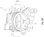
- throttle body assembly 20 also includes an outlet 28 coupled to body portion 24, as shown in Figs. 4A-6 .
- body portion 24 of throttle body assembly 20 includes a plurality of apertures 32 which are arranged in a staggered orientation.
- apertures 32 extend through bottom wall 24b of body portion 24, however, apertures 32 may extend through any of walls 24a, 24b, 24c, 24d.
- at least one aperture 32a is positioned downstream of throttle plate 26 and at least one aperture 32b is positioned upstream of throttle plate 26 when throttle plate 26 is in a fully closed position A ( Fig. 6 ).
- Fig. 6 the embodiment of Fig.
- each aperture 32 is positioned downstream of throttle plate 26 when throttle plate 26 is in the fully closed position A ( Fig. 6 ).
- Outlet 28 is positioned adjacent apertures 32 such that when a portion of air at air inlet 12 of engine 2 is received through apertures 32, that portion of air flows into outlet 28.
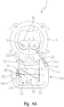
- an auxiliary or supplementary air circuit or assembly 40 is fluidly coupled to throttle body assembly 20 and intake port 14 of engine 2.
- Supplementary air assembly 40 includes a supplementary air inlet 42 and a supplementary air tube or hose 44.
- Supplementary air inlet 42 is fluidly coupled to cylinder 6 of engine 2 and, more particularly, is fluidly coupled to intake port 14 to provide air to combustion chamber 10 via intake port 14 for combustion at low load, idle conditions, or at other operating conditions of engine 2. More particularly, when engine 2 operates at low load or idle, throttle plate 26 may be nearly closed (e.g., throttle plate 26 may be positioned in a first intermediate position B ( Fig. 6 )) because there is no input to the throttle. However, air is still needed within combustion chamber 10 to maintain operation of engine 2 even at idle, low load, or other conditions of engine 2.
- illustrative supplementary air tube 44 has a first end 44a coupled to supplementary air inlet 42 and a second end 44b coupled to outlet 28.
- supplementary air tube 44 is positioned within an outer sleeve 46.
- Supplementary air tube 44 is configured to receive a flow of air at air inlet 12 which flows through supplementary air inlet 42, into intake port 14, and then into the combustion chamber 10 for combustion therein. When the air flows through supplementary air tube 44 and into supplementary air inlet 42, the turbulence of the air increases, which may increase the combustion rate within combustion chamber 10.
- throttle valve 22 in operation, when engine 2 is not operating, throttle valve 22 is closed and throttle plate 26 is positioned in the fully closed position A.
- throttle plate 26 when in the fully closed position A, throttle plate 26 extends between top and bottom walls 24a, 24b of body portion 24, and may be in contact with or sealed against walls 24, to block air flow into air inlet 12.
- air flow is not received within combustion chamber 10 or through apertures 32, which are positioned downstream of throttle plate 26 in the fully closed position A, such that the position and movement of throttle plate 26 controls the air flow to apertures 32.
- ECU 30 electronically controls operation of throttle body assembly 20 based on throttle conditions of engine 2 and/or other operating parameters of engine 2. For example, when a large throttle input occurs, ECU 30 transmits a signal to throttle body assembly 20 and throttle plate 26 is moved to the fully open position D. When throttle plate 26 is in the fully open position D, air flows through throttle valve 22, into air inlet 12, and into combustion chamber 10 for combustion therein. In the open positioned, throttle plate 26 is generally parallel to top and bottom walls 24a, 24b and extends in the same direction as the flow path of air into combustion chamber 10.
- ECU 30 transmits a signal to throttle body assembly 20 and throttle plate 26 may be opened to a first intermediate position B, a second intermediate position C, or any position between fully closed position A and fully open position D.
- throttle plate 26 may be opened to a first intermediate position B, a second intermediate position C, or any position between fully closed position A and fully open position D.
- throttle plate 26 when throttle plate 26 is at least partially opened, at least one aperture 32 is now upstream of throttle plate 26 and is exposed and a portion of air in throttle valve 22 flows through the exposed aperture(s) 32.
- the position of throttle plate 26 affects which apertures 32 receive air and/or the quantity of air received through apertures 32 such that the position of throttle plate 26 modulates and controls air flow through supplementary air assembly 40.
- a one-way valve 48 ( Fig. 4A ), for example a reed valve, is positioned adjacent apertures 32 to control the direction of air flow within supplementary air tube 44. More particularly, one-way valve 48 allows the flow of air in one direction toward supplementary air tube 44 but inhibits air flow in the opposite direction toward throttle valve 22.
- Figs. 4A-6 do not require the use of an air control valve 500 ( Fig. 3 ) because operation of supplementary air assembly 40 is controlled by throttle body assembly 20 of engine 2. As such, no additional valve or throttling mechanism is required to control the supplementary air entering intake port 14 and combustion chamber 10 because supplementary air assembly 40 is controlled and modulated by throttle body assembly 20.
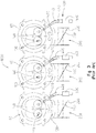
- an illustrative engine 2' includes three cylinders 6 1, 6 2 , 6 3 , however, engine 2' may include any number of cylinders.
- An alternative embodiment of throttle body assembly 20 is also shown as throttle body assembly 20' which is fluidly coupled to cylinders 6 1, 6 2 , 6 3 .
- Throttle body assembly 20' includes a throttle valve 22' fluidly coupled to air inlet 12 of each cylinder 6 1, 6 2 , 6 3 .
- Throttle valve 22' has a solid body portion 24' such that body portion 24' of throttle body assembly 20' does not include apertures 32.
- Throttle body assembly 20' is fluidly coupled to a supplementary air assembly 40' which includes supplementary air inlet 42 fluidly coupled to intake port 14 and supplementary air tubes 44 1 ', 44 2 ', 44 3 ' corresponding to cylinders 6 1, 6 2 , 6 3 , respectively. More particularly, supplementary air tube 44 1 ' has a first end 44a 1 ' coupled to supplementary air inlet 42 of cylinder 6 1 and a second end 44b 1 ' which extends into body portion 24' of cylinder 6 3 and is downstream of throttle plate 26.
- supplementary air tube 44 2 ' has a first end 44a 2 ' coupled to supplementary air inlet 42 of cylinder 6 2 and a second end 44b 2 ' which extends into body portion 24' of cylinder 6 1 and is downstream of throttle plate 26.
- Supplementary air tube 44 3 ' has a first end 44a 3 ' coupled to supplementary air inlet 42 of cylinder 6 3 and a second end 44b 3 ' which extends into body portion 24' of cylinder 6 2 and is downstream of throttle plate 26.
- cylinder 6 1, 6 2 , 6 3 are fluidly coupled to each other through supplementary air assembly 40'.
- a one-way valve 48 such as a reed valve, is positioned within any of supplementary air tubes 44 1 ', 44 2 ', 44 3 ' to control the direction of air flow therein.
- the combustion cycles of cylinders 6 1, 6 2 , 6 3 are out of phase with each other such that when one of cylinders 6 1, 6 2 , 6 3 is in one stroke of the combustion cycle (e.g., the power stroke), the other cylinders 6 1, 6 2 , 6 3 are in a different stroke (e.g., intake stroke, exhaust stroke, etc.). Because cylinders 6 1, 6 2 , 6 3 are out of phase with each other, there is a pressure difference between intake ports of cylinders 6 1, 6 2 , 6 3 , which facilitates air flow between the intake ports of cylinders 6 1, 6 2 , 6 3 through supplementary air assembly 40'.
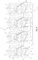
- an illustrative engine 2' includes four cylinders 6 1, 6 2 , 6 3 , 6 4 , but may include any number of cylinders.
- Throttle body assembly 20' is fluidly coupled to cylinders 6 1, 6 2 , 6 3 , 6 4 .
- Throttle body assembly 20' includes throttle valve 22' with the solid body portion 24' such that body portion 24' of throttle body assembly 20' does not include apertures 32.
- Supplementary air assembly 40 is fluidly coupled to throttle body assembly 20'.
- Supplementary air assembly 40" includes a first supplementary air tube 52 which has a first end 52a fluidly coupled to supplementary air inlet 42 of cylinder 6 1 and a second end fluidly coupled to supplementary air inlet 42 of cylinder 6 4 .
- supplementary air assembly 40" includes a second supplementary air tube 54 which has a first end 54a fluidly coupled to supplementary air inlet 42 of cylinder 6 2 and a second end 54b fluidly coupled to supplementary air inlet 42 of cylinder 6 3 .
- the combustion cycles of cylinders 6 1 , 6 2 , 6 3 , 6 4 are out of phase with each other such that when one of cylinders 6 1 , 6 2 , 6 3 , 6 4 is in one stroke of the combustion cycle (e.g., the power stroke), the other cylinders 6 1 , 6 2 , 6 3 , 6 4 are in a different stroke (e.g., intake stroke, exhaust stroke, etc.).
- one stroke of the combustion cycle e.g., the power stroke
- the other cylinders 6 1 , 6 2 , 6 3 , 6 4 are in a different stroke (e.g., intake stroke, exhaust stroke, etc.).
- cylinders 6 1 , 6 2 , 6 3 , 6 4 are out of phase with each other, there is a pressure difference between the intake port of cylinders 6 1 , 6 2 , 6 3 , 6 4 , which facilitates air flow between the intake port of cylinders 6 1 , 6 2 , 6 3 , 6 4 through supplementary air assembly 40".
- supplementary air assembly 40 For example, when pressure is high in the intake port of cylinder 6 1 , the pressure in the intake port of cylinder 6 4 is low which facilitates air flow through supplementary air tube 52 and into supplementary air inlet 42 of cylinder 6 4 .
Landscapes
- Engineering & Computer Science (AREA)
- Chemical & Material Sciences (AREA)
- Combustion & Propulsion (AREA)
- Mechanical Engineering (AREA)
- General Engineering & Computer Science (AREA)
- Control Of Throttle Valves Provided In The Intake System Or In The Exhaust System (AREA)
Description
- The present disclosure relates to a throttling mechanism for an engine and, more particularly, to a supplementary air throttling feature for supplying air to a supplementary intake air circuit of an internal combustion engine.
- To increase the efficiency of an engine, for example, when the engine is operating at low load or idle, faster combustion burn rates may be achieved by increasing turbulence in the combustion air entering the combustion chamber. By increasing the turbulence of the combustion air, better fuel-air mixing may occur.
- For example, as shown in
Fig. 3 , aninternal combustion engine 1000 includes at least onecylinder 60 with acombustion chamber 100 therein, anair inlet 120, and at least oneintake port 140. Athrottle body assembly 200 has abody portion 240 and athrottle plate 260, and asupplementary air assembly 400 includes a supplementary air inlet orport 420 and anair tube 440 for introducing a swirl into the combustion air to increase turbulence whenengine 1000 is operating at low load or idle conditions. An idleair control valve 500 may also be provided to control throttle atsupplementary air inlet 420. More particularly, in some embodiments, a flow of air travels throughair tube 440 andair inlet 420 and into theintake port 140 ofengine 1000. This air flow is not modulated by the throttle ofengine 1000, but rather, by the separate idleair control valve 500. An engine control unit may be electrically coupled to idleair control valve 500 to control idleair control valve 500 based on predetermined parameters and/or conditions ofengine 1000 during operation. - JPS54103913 discloses an internal combustion engine comprising a cylinder defining an internal combustion chamber and an air intake system comprising an air inlet and an intake port of the cylinder. The engine also comprises a supplementary fluid inlet coupled to the intake port.
US2008/053391 generally relates to an air-intake apparatus for an internal combustion engine. -
DE29811432 U1 generally relates to a pipe system, in particular an intake manifold system for an internal combustion engine. - JPH0216329 generally relates to an international combustion engine comprising an air inlet coupled to a throttle valve and a supplementary fluid inlet coupled to the intake port of a cylinder.
- The invention is set forth in
claim 1. Dependent claims recite advantageous embodiments of the invention. - Disclosed herein is an internal combustion engine including a crankcase including a crankshaft and at least one cylinder coupled to the crankcase. The at least one cylinder has an intake port and defines an internal combustion chamber. The engine further includes a throttle body assembly with a throttle valve coupled to an air inlet of the at least one cylinder and a throttle plate. Additionally, the engine includes a supplementary air inlet fluidly coupled to the intake port and spaced apart from the throttle valve. The supplementary air inlet is configured to receive a flow of air from a location downstream of the throttle plate when the throttle plate is in a fully closed position and the flow of air is directed into the combustion chamber through the intake port for combustion therein.
- Also disclosed herein is an internal combustion engine comprising a crankcase including a crankshaft; at least one cylinder coupled to the crankcase and having an intake port and the at least one cylinder defining an internal combustion chamber; a throttle body assembly having a throttle valve coupled to an air inlet of the at least one cylinder and including a throttle plate; a supplementary air inlet fluidly coupled to the intake port, wherein the supplementary air inlet is configured to receive a flow of air from a location downstream of the throttle plate of the at least one cylinder, and the flow of air is directed into the intake port of the at least one cylinder for combustion within the combustion chamber.
- Also disclosed herein is an internal combustion engine including a crankcase including a crankshaft and at least one cylinder coupled to the crankcase. The at least one cylinder defines an internal combustion chamber. The engine further includes a throttle body assembly with an inlet and an outlet fluidly coupled to an air inlet of the at least one cylinder. The throttle body assembly also includes a body portion and a throttle plate movably coupled within the body portion. The body portion includes a plurality of apertures. The engine also includes a supplementary air inlet fluidly coupled to the intake port and configured to receive air through at least one of the plurality of apertures of the body portion of the throttle body.
- Also disclosed herein is a throttle body assembly for use with an engine including a throttle port configured to fluidly couple with an air intake of the engine and has a body portion including a plurality of apertures. The throttle body assembly also includes a throttle plate movably coupled within the body portion and an outlet port coupled to the body portion and positioned adjacent the plurality of apertures.
- The above mentioned and other features, and the manner of attaining them, will become more apparent and the invention itself will be better understood by reference to the following description taken in conjunction with the accompanying drawings, where:
-
Fig. 1 is a perspective view of an illustrative two-cylinder internal combustion engine; -
Fig. 2 is a cross-sectional view of a cylinder head of one of the cylinders coupled to a throttle valve of a throttle body assembly of the engine ofFig. 1 ; -
Fig. 3 is a schematic view of three cylinders of an internal combustion engine each having a prior art air assembly with an idle air control valve; -
Fig. 4A is a schematic view of one cylinder of an engine of the present disclosure, including a first embodiment of a supplementary air assembly which includes a supplementary air inlet fluidly coupled to the throttle valve of the throttle body through a supplementary tube; -
Fig. 4B is a schematic view of one cylinder of an engine of the present disclosure, including an alternative embodiment of the supplementary air assembly ofFig. 4A which includes a supplementary air inlet fluidly coupled to the throttle valve through a tube; -
Fig. 5A is a perspective view of the throttle body ofFigs. 4A or4B having a throttle plate and a plurality of apertures extending through a wall of the throttle valve; -
Fig. 5B is a further perspective view of the throttle body ofFigs. 4A or4B shown in the open position and exposing the plurality of apertures; -
Fig. 6 is a cross-sectional view of the throttle valve ofFig. 5A , taken along line 6-6 ofFig. 5A ; -
Fig. 7 is a schematic view of three cylinders of an engine of the present disclosure including a second embodiment of a supplementary air assembly which includes a tube extending from a throttle valve of one cylinder to a supplementary air inlet of another cylinder; and -
Fig. 8 is a schematic view of four cylinders of an engine of the present disclosure including a third embodiment of a supplementary air assembly which includes a tube extending from a supplementary air inlet of one cylinder to a supplementary air inlet of another cylinder. - Corresponding reference characters indicate corresponding parts throughout the several views. Unless stated otherwise the drawings are proportional.
- The embodiments disclosed below are not intended to be exhaustive or to limit the invention to the precise forms disclosed in the following detailed description. Rather, the embodiments are chosen and described so that others skilled in the art may utilize their teachings. It should be understood that the invention as defined by the appended claims may have application to various types of engine-driven equipment, such as, but not limited to generators, construction equipment, utility equipment, all-terrain vehicles, motorcycles, watercraft, utility vehicles, scooters, golf carts, automobiles, aircraft, and mopeds, or any other device or vehicle with a spark-ignited, four-stroke engine.
- An illustrative embodiment of an
internal combustion engine 2 is shown inFig. 1 .Engine 2 includes acrankcase 4 and at least onecylinder 6. Illustratively,engine 2 includes twocylinders 6 in a V-shaped configuration; however,engine 2 may include any number of cylinder(s) 6 in any configuration possible forcylinder 6. Eachcylinder 6 includes acylinder head 8 defining a top end of eachcylinder 6. An internal combustion chamber 10 (Fig. 4A ) is defined within eachcylinder 6 and is configured for combustion therein during operation ofengine 2. - Referring to
Figs. 1 ,2 ,4A , and4B , eachcylinder 6 also includes anair inlet 12 for supplying air tocombustion chamber 10 for combustion.Engine 2 also includes at least oneintake port 14 and an exhaust port (not shown).Air inlet 12 andintake port 14 facilitate combustion withcombustion chamber 10. - Additionally, as shown in
Fig. 1 , athrottle body assembly 20 is coupled toengine 2 which includes a plurality ofthrottle valves 22 which are each fluidly coupled to theair inlet 12 of eachcylinder 6.Throttle valve 22 includes abody portion 24 and athrottle plate 26 movably coupled withinbody portion 24.Body portion 24 includes atop wall 24a, abottom wall 24b, a first side wall 24c, and asecond side wall 24d. Illustrativethrottle body assembly 20 may be electronically controlled by an engine control unit ("ECU") 30 to control operation ofthrottle body assembly 20, including movement ofthrottle plate 26. In one embodiment,throttle plate 26 is configured to rotatably move between at least positions A, B, C, D, and any position therebetween (Fig. 6 ). - In one embodiment,
throttle body assembly 20 also includes anoutlet 28 coupled tobody portion 24, as shown inFigs. 4A-6 . Additionally,body portion 24 ofthrottle body assembly 20 includes a plurality ofapertures 32 which are arranged in a staggered orientation. Illustratively,apertures 32 extend throughbottom wall 24b ofbody portion 24, however,apertures 32 may extend through any ofwalls Fig. 4A , at least oneaperture 32a is positioned downstream ofthrottle plate 26 and at least oneaperture 32b is positioned upstream ofthrottle plate 26 whenthrottle plate 26 is in a fully closed position A (Fig. 6 ). Conversely, in the embodiment ofFig. 4B , eachaperture 32 is positioned downstream ofthrottle plate 26 whenthrottle plate 26 is in the fully closed position A (Fig. 6 ).Outlet 28 is positionedadjacent apertures 32 such that when a portion of air atair inlet 12 ofengine 2 is received throughapertures 32, that portion of air flows intooutlet 28. - Referring still to
Figs. 4A-6 , an auxiliary or supplementary air circuit orassembly 40 is fluidly coupled to throttlebody assembly 20 andintake port 14 ofengine 2.Supplementary air assembly 40 includes asupplementary air inlet 42 and a supplementary air tube orhose 44.Supplementary air inlet 42 is fluidly coupled tocylinder 6 ofengine 2 and, more particularly, is fluidly coupled tointake port 14 to provide air tocombustion chamber 10 viaintake port 14 for combustion at low load, idle conditions, or at other operating conditions ofengine 2. More particularly, whenengine 2 operates at low load or idle,throttle plate 26 may be nearly closed (e.g.,throttle plate 26 may be positioned in a first intermediate position B (Fig. 6 )) because there is no input to the throttle. However, air is still needed withincombustion chamber 10 to maintain operation ofengine 2 even at idle, low load, or other conditions ofengine 2. - As shown in
Figs. 4A-6 , illustrativesupplementary air tube 44 has a first end 44a coupled tosupplementary air inlet 42 and asecond end 44b coupled tooutlet 28. In one embodiment,supplementary air tube 44 is positioned within anouter sleeve 46.Supplementary air tube 44 is configured to receive a flow of air atair inlet 12 which flows throughsupplementary air inlet 42, intointake port 14, and then into thecombustion chamber 10 for combustion therein. When the air flows throughsupplementary air tube 44 and intosupplementary air inlet 42, the turbulence of the air increases, which may increase the combustion rate withincombustion chamber 10. - Referring to
Fig. 6 , in operation, whenengine 2 is not operating,throttle valve 22 is closed andthrottle plate 26 is positioned in the fully closed position A. Illustratively, when in the fully closed position A,throttle plate 26 extends between top andbottom walls body portion 24, and may be in contact with or sealed againstwalls 24, to block air flow intoair inlet 12. As such, whenthrottle plate 26 is in the fully closed position A, air flow is not received withincombustion chamber 10 or throughapertures 32, which are positioned downstream ofthrottle plate 26 in the fully closed position A, such that the position and movement ofthrottle plate 26 controls the air flow to apertures 32. However, whenengine 2 is operating, air enterscombustion chamber 10 for combustion therein. More particularly,ECU 30 electronically controls operation ofthrottle body assembly 20 based on throttle conditions ofengine 2 and/or other operating parameters ofengine 2. For example, when a large throttle input occurs,ECU 30 transmits a signal to throttlebody assembly 20 andthrottle plate 26 is moved to the fully open position D. Whenthrottle plate 26 is in the fully open position D, air flows throughthrottle valve 22, intoair inlet 12, and intocombustion chamber 10 for combustion therein. In the open positioned,throttle plate 26 is generally parallel to top andbottom walls combustion chamber 10. - However, when
engine 2 is operating but the throttle input does not requireopening throttle valve 22 to the fully open position D, for example whenengine 2 is operating at low loads or at idle,ECU 30 transmits a signal to throttlebody assembly 20 andthrottle plate 26 may be opened to a first intermediate position B, a second intermediate position C, or any position between fully closed position A and fully open position D. As such, whenthrottle plate 26 is at least partially opened, at least oneaperture 32 is now upstream ofthrottle plate 26 and is exposed and a portion of air inthrottle valve 22 flows through the exposed aperture(s) 32. The position ofthrottle plate 26 affects which apertures 32 receive air and/or the quantity of air received throughapertures 32 such that the position ofthrottle plate 26 modulates and controls air flow throughsupplementary air assembly 40. The portion of air received through the exposed, upstream aperture(s) 32 then flows throughoutlet 28, intosupplementary air tube 44, throughsupplementary air inlet 42, intointake port 14, and then intocombustion chamber 10. In this way, combustion still occurs incombustion chamber 10 even whenengine 2 is at a low loads or at idle and the flow of air throughapertures 32 is controlled and modulated by the position ofthrottle plate 26 and operation ofthrottle body assembly 20. Furthermore, in the embodiment ofFig. 4A , even whenthrottle plate 26 is in the fully closed position A, air inthrottle valve 22 flows throughaperture 32b, which is upstream ofthrottle plate 26, and throughsupplementary air tube 44 for combustion incombustion chamber 10. - When air is in
throttle valve 22, air flows towardcombustion chamber 10. However, to prevent air from flowing in the opposite direction within supplementary air tube 44 (i.e., towards throttle valve 22), a one-way valve 48 (Fig. 4A ), for example a reed valve, is positionedadjacent apertures 32 to control the direction of air flow withinsupplementary air tube 44. More particularly, one-way valve 48 allows the flow of air in one direction towardsupplementary air tube 44 but inhibits air flow in the opposite direction towardthrottle valve 22. - It should be understood that the embodiments of
Figs. 4A-6 do not require the use of an air control valve 500 (Fig. 3 ) because operation ofsupplementary air assembly 40 is controlled bythrottle body assembly 20 ofengine 2. As such, no additional valve or throttling mechanism is required to control the supplementary air enteringintake port 14 andcombustion chamber 10 becausesupplementary air assembly 40 is controlled and modulated bythrottle body assembly 20. - Referring to
Fig. 7 , an illustrative engine 2' includes threecylinders 61, 62, 63, however, engine 2' may include any number of cylinders. An alternative embodiment ofthrottle body assembly 20 is also shown as throttle body assembly 20' which is fluidly coupled tocylinders 61, 62, 63. Throttle body assembly 20' includes a throttle valve 22' fluidly coupled toair inlet 12 of eachcylinder 61, 62, 63. Throttle valve 22' has a solid body portion 24' such that body portion 24' of throttle body assembly 20' does not includeapertures 32. - Throttle body assembly 20' is fluidly coupled to a supplementary air assembly 40' which includes
supplementary air inlet 42 fluidly coupled tointake port 14 and supplementary air tubes 441', 442', 443' corresponding tocylinders 61, 62, 63, respectively. More particularly, supplementary air tube 441' has a first end 44a1' coupled tosupplementary air inlet 42 ofcylinder 61 and asecond end 44b1' which extends into body portion 24' ofcylinder 63 and is downstream ofthrottle plate 26. Additionally, supplementary air tube 442' has a first end 44a2' coupled tosupplementary air inlet 42 ofcylinder 62 and asecond end 44b2' which extends into body portion 24' ofcylinder 61 and is downstream ofthrottle plate 26. Supplementary air tube 443' has a first end 44a3' coupled tosupplementary air inlet 42 ofcylinder 63 and asecond end 44b3' which extends into body portion 24' ofcylinder 62 and is downstream ofthrottle plate 26. As such,cylinder 61, 62, 63 are fluidly coupled to each other through supplementary air assembly 40'. In one embodiment, a one-way valve 48, such as a reed valve, is positioned within any of supplementary air tubes 441', 442', 443' to control the direction of air flow therein. - In operation, the combustion cycles of
cylinders 61, 62, 63 are out of phase with each other such that when one ofcylinders 61, 62, 63 is in one stroke of the combustion cycle (e.g., the power stroke), theother cylinders 61, 62, 63 are in a different stroke (e.g., intake stroke, exhaust stroke, etc.). Becausecylinders 61, 62, 63 are out of phase with each other, there is a pressure difference between intake ports ofcylinders 61, 62, 63, which facilitates air flow between the intake ports ofcylinders 61, 62, 63 through supplementary air assembly 40'. For example, when pressure is high in the intake port ofcylinder 61, the pressure in the intake port ofcylinder 62 is low which facilitates air flow through supplementary air tube 442' and intosupplementary air inlet 42 of the intake port ofcylinder 62. Additionally, when pressure is high in the intake port ofcylinder 62, pressure is low in the intake port ofcylinder 63 which facilitates air flow through supplementary air tube 443' and intosupplementary air inlet 42 ofcylinder 63. Similarly, when pressure is high in the intake port ofcylinder 63, pressure is low in the intake port ofcylinder 61 which facilitates air flow through supplementary air tube 441' and intosupplementary air inlet 42 ofcylinder 61. In this way, the embodiment ofFig. 7 does not require the use of air control valve 500 (Fig. 3 ) because operation of supplementary air assembly 40' is controlled and modulated by throttle body assembly 20' of engine 2'. As such, no additional valve or throttling mechanism is required and combustion occurs efficiently incombustion chambers 10 even when engine 2' is operating at low loads or at idle. - Referring to
Fig. 8 , an illustrative engine 2' includes fourcylinders 61, 62, 63, 64, but may include any number of cylinders. Throttle body assembly 20' is fluidly coupled tocylinders 61, 62, 63, 64. Throttle body assembly 20' includes throttle valve 22' with the solid body portion 24' such that body portion 24' of throttle body assembly 20' does not includeapertures 32. - Referring still to
Fig. 8 , a further alternative embodiment ofsupplementary air assemblies 40 and 40' is shown assupplementary air assembly 40".Supplementary air assembly 40" is fluidly coupled to throttle body assembly 20'.Supplementary air assembly 40" includes a firstsupplementary air tube 52 which has afirst end 52a fluidly coupled tosupplementary air inlet 42 ofcylinder 61 and a second end fluidly coupled tosupplementary air inlet 42 ofcylinder 64. Additionally,supplementary air assembly 40" includes a secondsupplementary air tube 54 which has afirst end 54a fluidly coupled tosupplementary air inlet 42 ofcylinder 62 and asecond end 54b fluidly coupled tosupplementary air inlet 42 ofcylinder 63. - In operation, the combustion cycles of
cylinders cylinders other cylinders cylinders cylinders cylinders supplementary air assembly 40". For example, when pressure is high in the intake port ofcylinder 61, the pressure in the intake port ofcylinder 64 is low which facilitates air flow throughsupplementary air tube 52 and intosupplementary air inlet 42 ofcylinder 64. Similarly, when pressure is high in the intake port ofcylinder 64, pressure is low in the intake port ofcylinder 61 which facilitates air flow throughsupplementary air tube 52 in the opposite direction and intosupplementary air inlet 42 ofcylinder 61. Additionally, when pressure is high in the intake port ofcylinder 63, pressure is low in the intake port ofcylinder 62 which facilitates air flow throughsupplementary air tube 54 and intosupplementary air inlet 42 ofcylinder 62. Similarly, when pressure is high in the intake port ofcylinder 62, pressure is low in the intake port ofcylinder 63 which facilitates air flow throughsupplementary air tube 54 in the opposite direction and intosupplementary air inlet 42 ofcylinder 63. In this way, the embodiment ofFig. 8 does not require the use of air control valve 500 (Fig. 3 ) because operation ofsupplementary air assembly 40" is controlled and modulated by throttle body assembly 20' ofengine 2". As such, no additional valve or throttling mechanism is required and combustion occurs efficiently incombustion chambers 10 even whenengine 2" is operating at low loads or at idle. - While this invention has been described as having an exemplary design, the present invention may be further modified within the scope of this disclosure. This application is therefore intended to cover any variations, uses, or adaptations of the invention as defined by the appended claims.
Claims (6)
- An internal combustion engine (2) comprising a crankcase (4) including
a crankshaft;
at least one cylinder (6; 6i, 62, 63, 64) coupled to the crankcase and defining an internal combustion chamber (10);
an air intake system comprising an air inlet (12) and an intake port (14) of the at least one cylinder, a supplementary air inlet (42) fluidly coupled to the intake port, and a throttle body assembly (20) having a throttle valve (22) coupled to the air inlet and including a throttle plate (26);
wherein the supplementary air inlet is configured to receive a flow of air from the air intake system of the at least one cylinder from a location downstream of the throttle plate, the flow of air is directed into the intake port of the at least one cylinder for combustion within the combustion chamber, and the flow of air is controlled and modulated by the position of the throttle plate;
characterized in that the throttle body assembly includes a plurality of apertures extending through a wall of the throttle body assembly; and in that a portion of the plurality of apertures are positioned downstream from the throttle plate when the throttle plate is in a fully closed position, and a portion of the apertures are configured to receive air when the throttle plate is in a fully closed position (A) and each of the apertures receives air when the throttle plate is in an open position (B, C, D);
and in that the plurality of apertures include at least one one-way valve (48) to allow the flow of air toward the supplementary air inlet but inhibit the flow of air in the opposite direction toward the throttle valve. - The engine of claim 1, characterized in that the flow of air is received through a supplementary air tube (44; 441', 442', 443', 52, 54) having first and second ends (44a, 44b; 44ai', 44bi'; 44a2', 44b2'; 44a3', 44b3'; 52a, 52b; 54a, 54b).
- The engine of claim 2, characterized in that the first end of the supplementary air tube (44a, 44a ; 44a2', 44a3') is positioned to direct air flow into the intake port and a second end (44b, 44bi', 44b2', 44b3) is positioned adjacent to the throttle valve.
- The engine of any of claims 1-3, characterized in that the supplementary air tube is positioned on a single cylinder.
- The engine of any of claims 1-4, characterized in that operation of the throttle body assembly is electronically controlled by an engine control unit.
- The engine of any of claims 1-5, characterized in that the flow of air directed into the intake port of the at least one cylinder for combustion within the combustion chamber is modulated by the throttle plate with no additional valve or throttling mechanism required.
Applications Claiming Priority (2)
| Application Number | Priority Date | Filing Date | Title |
|---|---|---|---|
| US201562129183P | 2015-03-06 | 2015-03-06 | |
| PCT/US2016/020357 WO2016144630A1 (en) | 2015-03-06 | 2016-03-02 | Supplementary air assembly for an engine |
Publications (2)
| Publication Number | Publication Date |
|---|---|
| EP3265666A1 EP3265666A1 (en) | 2018-01-10 |
| EP3265666B1 true EP3265666B1 (en) | 2021-04-28 |
Family
ID=55543085
Family Applications (1)
| Application Number | Title | Priority Date | Filing Date |
|---|---|---|---|
| EP16710564.2A Active EP3265666B1 (en) | 2015-03-06 | 2016-03-02 | Supplementary air assembly for an engine |
Country Status (8)
| Country | Link |
|---|---|
| US (1) | US10247148B2 (en) |
| EP (1) | EP3265666B1 (en) |
| JP (1) | JP6779222B2 (en) |
| CN (1) | CN107429641B (en) |
| AU (1) | AU2016229289B2 (en) |
| BR (1) | BR112017018762A2 (en) |
| CA (1) | CA2978309A1 (en) |
| WO (1) | WO2016144630A1 (en) |
Family Cites Families (36)
| Publication number | Priority date | Publication date | Assignee | Title |
|---|---|---|---|---|
| GB1195060A (en) * | 1966-10-05 | 1970-06-17 | Vergaser Ges M B H & Co K G De | Improvements in Induction Systems for Internal Combustion Engines. |
| US3437320A (en) * | 1966-11-10 | 1969-04-08 | Brooks Walker | Carburetor |
| DE2033624C2 (en) * | 1969-07-15 | 1982-12-16 | Alfa Romeo S.p.A., Milano | Device for manual adjustment of the idling speed of an internal combustion engine |
| JPS5624784B2 (en) * | 1973-07-24 | 1981-06-08 | ||
| US4867109A (en) * | 1976-11-26 | 1989-09-19 | Etsuhiro Tezuka | Intake passage arrangement for internal combustion engines |
| JPS6035533B2 (en) * | 1977-09-09 | 1985-08-15 | ヤマハ発動機株式会社 | engine intake system |
| JPS54103913A (en) * | 1978-02-01 | 1979-08-15 | Fuji Heavy Ind Ltd | Internal combustion engine |
| JPS54118915A (en) * | 1978-03-07 | 1979-09-14 | Toyota Motor Corp | Suction controller for internal combustion engine |
| JPS6060007B2 (en) * | 1978-05-22 | 1985-12-27 | トヨタ自動車株式会社 | Intake system for counterflow multi-cylinder internal combustion engine |
| JPS589249B2 (en) * | 1978-08-10 | 1983-02-19 | トヨタ自動車株式会社 | Intake system for multi-cylinder internal combustion engine |
| JPS5583528U (en) * | 1978-12-04 | 1980-06-09 | ||
| JPS5583528A (en) | 1978-12-18 | 1980-06-24 | Inoue Japax Res Inc | Wire cut electrical discharge machining device |
| JPS5627025A (en) * | 1979-08-10 | 1981-03-16 | Honda Motor Co Ltd | Suction device in internal-combustion engine |
| JPS5783631A (en) * | 1980-11-13 | 1982-05-25 | Suzuki Motor Co Ltd | Internal combustion engine |
| US4516544A (en) * | 1982-05-25 | 1985-05-14 | Toyota Jidosha Kabushiki Kaisha | Helically-shaped intake port of an internal-combustion engine |
| JPS6134317A (en) * | 1984-07-26 | 1986-02-18 | Suzuki Motor Co Ltd | Intake controlling of internal-combustion engine |
| US4934331A (en) * | 1988-06-09 | 1990-06-19 | Pommer Fredi A | Additional air supply means for an internal combustion engine |
| JPH02144623A (en) | 1988-11-25 | 1990-06-04 | Seiko Instr Inc | Computing mechanism for prevention of column truncation |
| JPH02107758U (en) * | 1989-02-14 | 1990-08-28 | ||
| US5005535A (en) * | 1989-02-27 | 1991-04-09 | Outboard Marine Corporation | Internal Combustion engine with recessed intake manifold |
| JPH02144623U (en) * | 1989-05-10 | 1990-12-07 | ||
| JPH0216329A (en) * | 1989-05-24 | 1990-01-19 | Yamaha Motor Co Ltd | Intake device of engine |
| US5022355A (en) * | 1990-04-23 | 1991-06-11 | Outboard Motor Corporation | Internal combustion engine |
| US5035211A (en) * | 1990-04-23 | 1991-07-30 | Outboard Marine Corporation | Internal combustion engine |
| US5261231A (en) * | 1991-04-02 | 1993-11-16 | Huh Chan Hoi | Intake/exhaust air pressure balancer and method of reducing intake/exhaust air pressure resistance |
| SE502371C2 (en) * | 1991-07-10 | 1995-10-09 | Volvo Ab | Device for suction engine combustion systems |
| JPH0693866A (en) * | 1992-09-11 | 1994-04-05 | Suzuki Motor Corp | Intake system for engine |
| US5377650A (en) * | 1993-10-26 | 1995-01-03 | Walbro Corporation | Low emission engines |
| DE29811432U1 (en) * | 1998-06-26 | 1998-09-03 | Mann & Hummel Filter | Pipe system, especially intake manifold system for an internal combustion engine |
| JP2002364467A (en) * | 2001-06-08 | 2002-12-18 | Yamaha Motor Co Ltd | Intake device for engine |
| JP3726901B2 (en) * | 2002-08-09 | 2005-12-14 | 株式会社日立製作所 | Internal combustion engine control device and swirl generator |
| AU2002952646A0 (en) * | 2002-11-12 | 2002-11-28 | HUNTER, Shane | A crankcase breather for a motorcycle engine |
| JP2008057345A (en) * | 2006-08-29 | 2008-03-13 | Denso Corp | Intake device |
| US20080141968A1 (en) * | 2006-12-18 | 2008-06-19 | Gm Global Technology Operations, Inc. | Intake manifold assembly |
| JP2010116870A (en) * | 2008-11-13 | 2010-05-27 | Yamaha Motor Co Ltd | Internal combustion engine for vehicle |
| US8181634B2 (en) * | 2010-05-17 | 2012-05-22 | GM Global Technology Operations LLC | Engine including positive crankcase ventilation |
-
2016
- 2016-03-02 JP JP2017546207A patent/JP6779222B2/en active Active
- 2016-03-02 AU AU2016229289A patent/AU2016229289B2/en not_active Ceased
- 2016-03-02 EP EP16710564.2A patent/EP3265666B1/en active Active
- 2016-03-02 CA CA2978309A patent/CA2978309A1/en not_active Abandoned
- 2016-03-02 BR BR112017018762A patent/BR112017018762A2/en not_active IP Right Cessation
- 2016-03-02 WO PCT/US2016/020357 patent/WO2016144630A1/en active Application Filing
- 2016-03-02 CN CN201680013671.9A patent/CN107429641B/en active Active
- 2016-03-07 US US15/062,898 patent/US10247148B2/en active Active
Non-Patent Citations (1)
| Title |
|---|
| None * |
Also Published As
| Publication number | Publication date |
|---|---|
| US10247148B2 (en) | 2019-04-02 |
| JP2018511728A (en) | 2018-04-26 |
| CA2978309A1 (en) | 2016-09-15 |
| AU2016229289A1 (en) | 2017-09-28 |
| BR112017018762A2 (en) | 2018-04-17 |
| US20160258393A1 (en) | 2016-09-08 |
| CN107429641A (en) | 2017-12-01 |
| CN107429641B (en) | 2020-08-21 |
| AU2016229289B2 (en) | 2019-10-10 |
| EP3265666A1 (en) | 2018-01-10 |
| JP6779222B2 (en) | 2020-11-04 |
| WO2016144630A1 (en) | 2016-09-15 |
Similar Documents
| Publication | Publication Date | Title |
|---|---|---|
| US6234154B1 (en) | Integral PCV system | |
| US6672296B2 (en) | Cylinder head structure in multi-cylinder engine | |
| EP1447533B1 (en) | Blowby gas circulating apparatus for an internal combustion engine | |
| JP4923036B2 (en) | Exhaust gas recirculation device for internal combustion engine | |
| US8371254B2 (en) | Fuel injector cooling | |
| CN107269428B (en) | Exhaust gas recirculation device | |
| US10119439B2 (en) | Blow-by gas recirculating apparatus | |
| JP2005113844A (en) | Intake system of internal combustion engine | |
| JP4652303B2 (en) | Multi-cylinder internal combustion engine with exhaust gas recirculation device | |
| US7673620B2 (en) | Internal combustion engine with breather chamber | |
| EP3265666B1 (en) | Supplementary air assembly for an engine | |
| US10851742B2 (en) | Intake system for vehicle | |
| US20130104817A1 (en) | Engine assembly including crankcase ventilation system | |
| JP6933700B2 (en) | Head cover structure | |
| JP4079828B2 (en) | Internal combustion engine with a PCV valve | |
| CN111188669B (en) | Air-oil separator | |
| JP2010031685A (en) | Spark ignition internal combustion engine | |
| JP2010031688A (en) | Spark-ignition internal combustion engine | |
| US6782864B2 (en) | Mount structure for an engine accessory | |
| JP2004245114A (en) | Intake manifold of v-type engine | |
| JP2010053737A (en) | Control device of internal combustion engine and cooling system of internal combustion engine | |
| JP2003035136A (en) | Secondary air supply structure for internal combustion engine | |
| JP6795465B2 (en) | Blow-by gas reflux device | |
| EP2912297B1 (en) | Intake assembly for an internal combustion engine and internal combustion engine with the same | |
| WO2020095965A1 (en) | Intake structure of internal combustion engine |
Legal Events
| Date | Code | Title | Description |
|---|---|---|---|
| STAA | Information on the status of an ep patent application or granted ep patent |
Free format text: STATUS: THE INTERNATIONAL PUBLICATION HAS BEEN MADE |
|
| PUAI | Public reference made under article 153(3) epc to a published international application that has entered the european phase |
Free format text: ORIGINAL CODE: 0009012 |
|
| STAA | Information on the status of an ep patent application or granted ep patent |
Free format text: STATUS: REQUEST FOR EXAMINATION WAS MADE |
|
| 17P | Request for examination filed |
Effective date: 20170901 |
|
| AK | Designated contracting states |
Kind code of ref document: A1 Designated state(s): AL AT BE BG CH CY CZ DE DK EE ES FI FR GB GR HR HU IE IS IT LI LT LU LV MC MK MT NL NO PL PT RO RS SE SI SK SM TR |
|
| AX | Request for extension of the european patent |
Extension state: BA ME |
|
| DAV | Request for validation of the european patent (deleted) | ||
| DAX | Request for extension of the european patent (deleted) | ||
| STAA | Information on the status of an ep patent application or granted ep patent |
Free format text: STATUS: EXAMINATION IS IN PROGRESS |
|
| 17Q | First examination report despatched |
Effective date: 20190313 |
|
| GRAP | Despatch of communication of intention to grant a patent |
Free format text: ORIGINAL CODE: EPIDOSNIGR1 |
|
| STAA | Information on the status of an ep patent application or granted ep patent |
Free format text: STATUS: GRANT OF PATENT IS INTENDED |
|
| INTG | Intention to grant announced |
Effective date: 20201117 |
|
| GRAS | Grant fee paid |
Free format text: ORIGINAL CODE: EPIDOSNIGR3 |
|
| GRAA | (expected) grant |
Free format text: ORIGINAL CODE: 0009210 |
|
| STAA | Information on the status of an ep patent application or granted ep patent |
Free format text: STATUS: THE PATENT HAS BEEN GRANTED |
|
| AK | Designated contracting states |
Kind code of ref document: B1 Designated state(s): AL AT BE BG CH CY CZ DE DK EE ES FI FR GB GR HR HU IE IS IT LI LT LU LV MC MK MT NL NO PL PT RO RS SE SI SK SM TR |
|
| REG | Reference to a national code |
Ref country code: GB Ref legal event code: FG4D |
|
| REG | Reference to a national code |
Ref country code: CH Ref legal event code: EP |
|
| REG | Reference to a national code |
Ref country code: AT Ref legal event code: REF Ref document number: 1387335 Country of ref document: AT Kind code of ref document: T Effective date: 20210515 |
|
| REG | Reference to a national code |
Ref country code: DE Ref legal event code: R096 Ref document number: 602016056832 Country of ref document: DE |
|
| REG | Reference to a national code |
Ref country code: IE Ref legal event code: FG4D |
|
| REG | Reference to a national code |
Ref country code: LT Ref legal event code: MG9D |
|
| REG | Reference to a national code |
Ref country code: AT Ref legal event code: MK05 Ref document number: 1387335 Country of ref document: AT Kind code of ref document: T Effective date: 20210428 |
|
| PG25 | Lapsed in a contracting state [announced via postgrant information from national office to epo] |
Ref country code: FI Free format text: LAPSE BECAUSE OF FAILURE TO SUBMIT A TRANSLATION OF THE DESCRIPTION OR TO PAY THE FEE WITHIN THE PRESCRIBED TIME-LIMIT Effective date: 20210428 Ref country code: LT Free format text: LAPSE BECAUSE OF FAILURE TO SUBMIT A TRANSLATION OF THE DESCRIPTION OR TO PAY THE FEE WITHIN THE PRESCRIBED TIME-LIMIT Effective date: 20210428 Ref country code: NL Free format text: LAPSE BECAUSE OF FAILURE TO SUBMIT A TRANSLATION OF THE DESCRIPTION OR TO PAY THE FEE WITHIN THE PRESCRIBED TIME-LIMIT Effective date: 20210428 Ref country code: BG Free format text: LAPSE BECAUSE OF FAILURE TO SUBMIT A TRANSLATION OF THE DESCRIPTION OR TO PAY THE FEE WITHIN THE PRESCRIBED TIME-LIMIT Effective date: 20210728 Ref country code: AT Free format text: LAPSE BECAUSE OF FAILURE TO SUBMIT A TRANSLATION OF THE DESCRIPTION OR TO PAY THE FEE WITHIN THE PRESCRIBED TIME-LIMIT Effective date: 20210428 Ref country code: HR Free format text: LAPSE BECAUSE OF FAILURE TO SUBMIT A TRANSLATION OF THE DESCRIPTION OR TO PAY THE FEE WITHIN THE PRESCRIBED TIME-LIMIT Effective date: 20210428 |
|
| PG25 | Lapsed in a contracting state [announced via postgrant information from national office to epo] |
Ref country code: GR Free format text: LAPSE BECAUSE OF FAILURE TO SUBMIT A TRANSLATION OF THE DESCRIPTION OR TO PAY THE FEE WITHIN THE PRESCRIBED TIME-LIMIT Effective date: 20210729 Ref country code: LV Free format text: LAPSE BECAUSE OF FAILURE TO SUBMIT A TRANSLATION OF THE DESCRIPTION OR TO PAY THE FEE WITHIN THE PRESCRIBED TIME-LIMIT Effective date: 20210428 Ref country code: IS Free format text: LAPSE BECAUSE OF FAILURE TO SUBMIT A TRANSLATION OF THE DESCRIPTION OR TO PAY THE FEE WITHIN THE PRESCRIBED TIME-LIMIT Effective date: 20210828 Ref country code: SE Free format text: LAPSE BECAUSE OF FAILURE TO SUBMIT A TRANSLATION OF THE DESCRIPTION OR TO PAY THE FEE WITHIN THE PRESCRIBED TIME-LIMIT Effective date: 20210428 Ref country code: RS Free format text: LAPSE BECAUSE OF FAILURE TO SUBMIT A TRANSLATION OF THE DESCRIPTION OR TO PAY THE FEE WITHIN THE PRESCRIBED TIME-LIMIT Effective date: 20210428 Ref country code: NO Free format text: LAPSE BECAUSE OF FAILURE TO SUBMIT A TRANSLATION OF THE DESCRIPTION OR TO PAY THE FEE WITHIN THE PRESCRIBED TIME-LIMIT Effective date: 20210728 Ref country code: PL Free format text: LAPSE BECAUSE OF FAILURE TO SUBMIT A TRANSLATION OF THE DESCRIPTION OR TO PAY THE FEE WITHIN THE PRESCRIBED TIME-LIMIT Effective date: 20210428 Ref country code: PT Free format text: LAPSE BECAUSE OF FAILURE TO SUBMIT A TRANSLATION OF THE DESCRIPTION OR TO PAY THE FEE WITHIN THE PRESCRIBED TIME-LIMIT Effective date: 20210830 |
|
| REG | Reference to a national code |
Ref country code: NL Ref legal event code: MP Effective date: 20210428 |
|
| PG25 | Lapsed in a contracting state [announced via postgrant information from national office to epo] |
Ref country code: SK Free format text: LAPSE BECAUSE OF FAILURE TO SUBMIT A TRANSLATION OF THE DESCRIPTION OR TO PAY THE FEE WITHIN THE PRESCRIBED TIME-LIMIT Effective date: 20210428 Ref country code: SM Free format text: LAPSE BECAUSE OF FAILURE TO SUBMIT A TRANSLATION OF THE DESCRIPTION OR TO PAY THE FEE WITHIN THE PRESCRIBED TIME-LIMIT Effective date: 20210428 Ref country code: EE Free format text: LAPSE BECAUSE OF FAILURE TO SUBMIT A TRANSLATION OF THE DESCRIPTION OR TO PAY THE FEE WITHIN THE PRESCRIBED TIME-LIMIT Effective date: 20210428 Ref country code: CZ Free format text: LAPSE BECAUSE OF FAILURE TO SUBMIT A TRANSLATION OF THE DESCRIPTION OR TO PAY THE FEE WITHIN THE PRESCRIBED TIME-LIMIT Effective date: 20210428 Ref country code: DK Free format text: LAPSE BECAUSE OF FAILURE TO SUBMIT A TRANSLATION OF THE DESCRIPTION OR TO PAY THE FEE WITHIN THE PRESCRIBED TIME-LIMIT Effective date: 20210428 Ref country code: ES Free format text: LAPSE BECAUSE OF FAILURE TO SUBMIT A TRANSLATION OF THE DESCRIPTION OR TO PAY THE FEE WITHIN THE PRESCRIBED TIME-LIMIT Effective date: 20210428 Ref country code: RO Free format text: LAPSE BECAUSE OF FAILURE TO SUBMIT A TRANSLATION OF THE DESCRIPTION OR TO PAY THE FEE WITHIN THE PRESCRIBED TIME-LIMIT Effective date: 20210428 |
|
| REG | Reference to a national code |
Ref country code: DE Ref legal event code: R097 Ref document number: 602016056832 Country of ref document: DE |
|
| PLBE | No opposition filed within time limit |
Free format text: ORIGINAL CODE: 0009261 |
|
| STAA | Information on the status of an ep patent application or granted ep patent |
Free format text: STATUS: NO OPPOSITION FILED WITHIN TIME LIMIT |
|
| 26N | No opposition filed |
Effective date: 20220131 |
|
| PG25 | Lapsed in a contracting state [announced via postgrant information from national office to epo] |
Ref country code: IS Free format text: LAPSE BECAUSE OF FAILURE TO SUBMIT A TRANSLATION OF THE DESCRIPTION OR TO PAY THE FEE WITHIN THE PRESCRIBED TIME-LIMIT Effective date: 20210828 Ref country code: AL Free format text: LAPSE BECAUSE OF FAILURE TO SUBMIT A TRANSLATION OF THE DESCRIPTION OR TO PAY THE FEE WITHIN THE PRESCRIBED TIME-LIMIT Effective date: 20210428 |
|
| PG25 | Lapsed in a contracting state [announced via postgrant information from national office to epo] |
Ref country code: IT Free format text: LAPSE BECAUSE OF FAILURE TO SUBMIT A TRANSLATION OF THE DESCRIPTION OR TO PAY THE FEE WITHIN THE PRESCRIBED TIME-LIMIT Effective date: 20210428 |
|
| PG25 | Lapsed in a contracting state [announced via postgrant information from national office to epo] |
Ref country code: MC Free format text: LAPSE BECAUSE OF FAILURE TO SUBMIT A TRANSLATION OF THE DESCRIPTION OR TO PAY THE FEE WITHIN THE PRESCRIBED TIME-LIMIT Effective date: 20210428 |
|
| REG | Reference to a national code |
Ref country code: CH Ref legal event code: PL |
|
| REG | Reference to a national code |
Ref country code: BE Ref legal event code: MM Effective date: 20220331 |
|
| PG25 | Lapsed in a contracting state [announced via postgrant information from national office to epo] |
Ref country code: LU Free format text: LAPSE BECAUSE OF NON-PAYMENT OF DUE FEES Effective date: 20220302 Ref country code: LI Free format text: LAPSE BECAUSE OF NON-PAYMENT OF DUE FEES Effective date: 20220331 Ref country code: IE Free format text: LAPSE BECAUSE OF NON-PAYMENT OF DUE FEES Effective date: 20220302 Ref country code: CH Free format text: LAPSE BECAUSE OF NON-PAYMENT OF DUE FEES Effective date: 20220331 |
|
| PG25 | Lapsed in a contracting state [announced via postgrant information from national office to epo] |
Ref country code: BE Free format text: LAPSE BECAUSE OF NON-PAYMENT OF DUE FEES Effective date: 20220331 |
|
| PGFP | Annual fee paid to national office [announced via postgrant information from national office to epo] |
Ref country code: FR Payment date: 20230222 Year of fee payment: 8 |
|
| PGFP | Annual fee paid to national office [announced via postgrant information from national office to epo] |
Ref country code: GB Payment date: 20230222 Year of fee payment: 8 Ref country code: DE Payment date: 20230221 Year of fee payment: 8 |
|
| P01 | Opt-out of the competence of the unified patent court (upc) registered |
Effective date: 20230514 |
|
| PG25 | Lapsed in a contracting state [announced via postgrant information from national office to epo] |
Ref country code: HU Free format text: LAPSE BECAUSE OF FAILURE TO SUBMIT A TRANSLATION OF THE DESCRIPTION OR TO PAY THE FEE WITHIN THE PRESCRIBED TIME-LIMIT; INVALID AB INITIO Effective date: 20160302 |
|
| PG25 | Lapsed in a contracting state [announced via postgrant information from national office to epo] |
Ref country code: MK Free format text: LAPSE BECAUSE OF FAILURE TO SUBMIT A TRANSLATION OF THE DESCRIPTION OR TO PAY THE FEE WITHIN THE PRESCRIBED TIME-LIMIT Effective date: 20210428 Ref country code: CY Free format text: LAPSE BECAUSE OF FAILURE TO SUBMIT A TRANSLATION OF THE DESCRIPTION OR TO PAY THE FEE WITHIN THE PRESCRIBED TIME-LIMIT Effective date: 20210428 |
|
| PGFP | Annual fee paid to national office [announced via postgrant information from national office to epo] |
Ref country code: DE Payment date: 20240220 Year of fee payment: 9 Ref country code: GB Payment date: 20240220 Year of fee payment: 9 |