JP4079828B2 - Internal combustion engine with a PCV valve - Google Patents
Internal combustion engine with a PCV valve Download PDFInfo
- Publication number
- JP4079828B2 JP4079828B2 JP2003141012A JP2003141012A JP4079828B2 JP 4079828 B2 JP4079828 B2 JP 4079828B2 JP 2003141012 A JP2003141012 A JP 2003141012A JP 2003141012 A JP2003141012 A JP 2003141012A JP 4079828 B2 JP4079828 B2 JP 4079828B2
- Authority
- JP
- Japan
- Prior art keywords
- pcv valve
- breather chamber
- bracket
- internal combustion
- combustion engine
- Prior art date
- Legal status (The legal status is an assumption and is not a legal conclusion. Google has not performed a legal analysis and makes no representation as to the accuracy of the status listed.)
- Expired - Fee Related
Links
Images


Description
【0001】
【発明の属する技術分野】
本願発明は、車両に搭載された内燃機関であって、ブローバイガス還元装置におけるPCV(Positive Crankcase Ventilation)バルブを備える内燃機関に関する。
【0002】
【従来の技術】
従来、内燃機関では、クランクケース内のブローバイガスを吸気系に還流し、再度燃焼室に吸入させて燃焼させるために、ブローバイガス還元装置が設けられる。このブローバイガス還元装置には、ブローバイガスに混入しているオイルが吸気系に流入して、オイルが吸気系の装置に付着する不都合やオイルの消費量が増加するのを防止するために、ブローバイガス中のオイルを分離するためのブリーザ室が設けられ、さらにブローバイガスの発生量に対応して、吸気系に還流されるブローバイガスの還流量を吸気負圧に応じて調整するPCVバルブが設けられる。
【0003】
そして、ブリーザ室が設けられたブローバイガス還元装置では、通常、PCVバルブはブリーザ室を形成する形成部材に、直接またはグロメットを介して取り付けられる。例えば特許第2888383号公報に開示された技術では、相互に近接したサージタンクとシリンダブロックの側壁との間に配置されたブリーザ室が、シリンダブロックの側壁に設けられたブリーザ凹部と、該ブリーザ凹部に固定される蓋板(形成部材に相当)とで形成され、PCVバルブは、グロメッットを介して該蓋板に取り付けられる。
【0004】
【発明が解決しようとする課題】
ところで、このようにPCVバルブがブリーザ室を形成する形成部材に取り付けられるものでは、PCVバルブ自体が小さいため、該形成部材の外側面からの突出量も小さいこと、また、ブリーザ室がシリンダブロックに形成された内燃機関では、前記公報に開示されたブリーザ室のように、ブリーザ室が吸気装置(サージタンク)の背後あるいは側方に配置されて、PCVバルブも該吸気装置の背後あるいは側方に位置したり、あるいはPCVバルブがシリンダブロックに取り付けられた補機類の背後あるいは側方に位置することが多く、メンテナンスに伴うPCVバルブの脱着作業が効率的になされず、PCVバルブのメンテナンスの作業性が良好ではなかった。
【0005】
本願発明は、このような事情に鑑みてなされたものであって、請求項1ないし請求項3記載の発明は、車両に搭載された内燃機関において、補機の背後に形成されたブリーザ室から吸気系にブローバイガスを導く還流路に設けられたPCVバルブの脱着を容易にして、PCVバルブのメンテナンスの作業性の向上を図ることを共通の目的とする。そして、請求項2記載の発明は、さらに、PCVバルブの配置の自由度を増して、PCVバルブの脱着性を向上させることを目的とし、請求項3記載の発明は、さらに、PCVバルブに接続されてブローバイガスを吸気系に導く接続ホースの取付け作業を容易にすることを目的とする。
【0006】
【課題を解決するための手段および発明の効果】
本願の請求項1記載の発明は、車両に搭載された内燃機関であって、補機が取り付けられた補機用のブラケットと、ブリーザ室を形成するシリンダブロックと、ブローバイガスを前記ブリーザ室から吸気系に導く還流路に設けられたPCVバルブとを備える内燃機関において、前記ブリーザ室は、前記補機の背後において前記シリンダブロックと前記ブラケットとによりに形成され、前記還流路は前記ブラケットに形成されて前記ブリーザ室に連通する連通路を含み、前記連通路を介して前記ブリーザ室に連通する前記PCVバルブは、前記補機の前記ブリーザ室寄りの部分よりも前方で、かつ前記補機の上方に、外部に露出した状態で、前記補機に近接して配置されている内燃機関である。
【0007】
この請求項1記載の発明によれば、補機に近接して配置されたPCVバルブは、補機が取り付けられたブラケットに形成された連通路を介して補機の背後に形成されたブリーザ室に連通し、しかも補機のブリーザ室寄りの部分よりも前方で、かつ補機の上方に、外部に露出した状態で配置されるので、補機に対して、より前側でかつ上方において、ブリーザ室の前方に位置する補機を避けた、脱着し易い位置に配置される。
【0008】
その結果、次の効果が奏される。すなわち、PCVバルブは補機を避けた脱着し易い位置に配置されるので、補機に近接して配置されたPCVバルブの脱着が容易になって、PCVバルブのメンテナンスの作業性が向上する。
【0009】
請求項2記載の発明は、請求項1記載の内燃機関において、前記連通路は、前記ブラケットの、前記部分よりも前方に位置すると共に前記補機の上方に位置する前面に開口する開口部を有し、前記PCVバルブは、前記開口部にて前記ブラケットに取り付けられた接続管を介して前記連通路に連通し、前記接続管の、前記前面から前方に突出すると共に前記補機の上方に位置する突出部に、前記PCVバルブが取り付けられているものである。
【0010】
この請求項2記載の発明によれば、ブラケットにおいて連通路の開口部が開口する前面は、補機のブリーザ室寄りの部分よりも前方で、かつ補機の上方に位置し、PCVバルブが取り付けられる接続管の突出部は前記前面から前方に突出しているため、PCVバルブは、その突出している分、前記前面から前方に離れて位置し、補機に対してより前側に位置することになるので、脱着し易い位置に配置される。また、連通路に接続される接続管が使用されるため、PCVバルブの位置が連通路の位置の制約を受けることが少なくなる。
【0011】
その結果、請求項1記載の発明の効果に加えて、次の効果が奏される。すなわち、PCVバルブの位置がブラケットに形成される連通路の位置の制約を受けることが少なくなるので、PCVバルブの配置の自由度が増加して、その脱着性が向上する。
【0012】
請求項3記載の発明は、請求項2記載の内燃機関において、前記PCVバルブには、 前記還流路の構成要素であると共にブローバイガスを前記吸気系に導く接続ホースが接続され、前記接続管は、前記吸気系での還流位置に近くなる方向に屈曲している曲管であるものである。
【0013】
この請求項3記載の発明によれば、接続管が曲管であるので、直管である場合に比べて、PCVバルブの配置の自由度が一層増加し、また接続管が吸気系でのブローバイガスの還流位置に近くなる方向に屈曲するので、接続ホースの長さを短縮することができる。
【0014】
その結果、引用された請求項記載の発明の効果に加えて、次の効果が奏される。すなわち、PCVバルブの配置の自由度が一層増加するので、PCVバルブの脱着性が向上し、さらに接続ホースの取付け作業が容易になる。
【0015】
【発明の実施の形態】
以下、本願発明の実施例を図1ないし図4を参照して説明する。
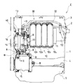
本願発明が適用される内燃機関の正面図である図1を参照すると、内燃機関Eは、車両に搭載される頭上カム軸式の直列4気筒の水冷式4サイクル内燃機関であり、左右方向を指向するクランク軸(図示されず)を回転自在に支持するシリンダブロック1の上端にシリンダヘッド2が、さらにシリンダヘッド2の上端にヘッドカバー3が結合される一方、シリンダブロック1の下端にロアブロック4が結合され、該ロアブロック4の下端にオイルパン5が結合される。そして、シリンダブロック1の下部とロアブロック4とオイルパン5とによりクランク室6(図2参照)が形成され、シリンダヘッド2とヘッドカバー3とにより動弁室が形成される。シリンダブロック1には、クランク軸側から若干後傾して延びる中心軸線を有する4つのシリンダ(図2には、そのうちの第1シリンダ7が示されている)が設けられ、前記各シリンダのボア(図2には、そのうちの第1シリンダ7のボア7aが示されている)内にピストン(図示されず)が摺動自在に嵌合し、該ピストンの往復動がコンロッドを介してクランク軸の回転動に変換される。
【0016】
なお、この明細書において、「前後左右」は、特に断らない限り、車両を基準としたときの「前後左右」を意味するものとする。
【0017】
シリンダブロック1の一側面である前面には、吸気マニホルド10を構成する4つの吸気管101〜104が並列配置され、各吸気管101〜104の下流端はシリンダヘッド2の4つの吸気ポートに連通する一方、その上流端はサージタンク11に接続され、該サージタンク11の上流端に、スロットル弁を有するスロットルボディ12が接続される。吸気マニホルド10の右方には、シリンダブロック1に複数のボルトBにより締結される補機用のブラケット20が配置され、該ブラケット20には、補機類、この実施例では油圧式パワーステアリング用の油圧を発生する油圧ポンプ13、交流発電機14、空調用のコンプレッサ15、およびウォータポンプ(図示されず)が取り付けられ、これらの補機は、伝動ベルト16を介して伝達されるクランク軸の動力により回転駆動される。
【0018】
図2も併せて参照すると、ブリーザ室21は、シリンダブロック1に形成された第1凹部22とブラケット20に形成された第2凹部23とにより形成される。第1凹部22は、前記シリンダのうち右端に位置する第1シリンダ7の前方のシリンダブロック1の前面において、シリンダブロック1の一部が前方から見て略矩形の枠を形成するように前方に突出する上下左右の各突出部を、シリンダブロック1側の上壁1a、下壁1b、右壁(図示されず)および左壁1cとして、それら4つの側壁W1に囲まれ、第1シリンダ7の冷却水ジャケット24を形成するシリンダ壁を底壁1dとして形成される。また、第2凹部23は、ブラケット20における発電機14の取付け部分の背面において、シリンダブロック1側の前記4つの側壁W1の前端面が合わせ面Pとなるように、後方に突出して略矩形の枠を形成する上下左右の突出部をブラケット20側の上壁20a、下壁20b、右壁(図示されず)および左壁20dとして、それら4つの側壁W2に囲まれて形成される。そして、この第2凹部23の底壁20dは、発電機14の前記取付け部分により形成され、さらに下壁20bと底壁20dとの交差部には、ラジエータ(図示されず)から開状態にあるサーモスタット(図示されず)を経た冷却水を冷却水ポンプのポンプ室に導入するための導入通路25が形成され、該導入通路25の通路壁25aが、ブリーザ室21内に膨出している。それゆえ、ブリーザ室21は、シリンダブロック1およびブラケット20を形成部材として形成される。また、ブリーザ室 21 は、発電機 14 の背後にシリンダブロック1とブラケット 20 とによりに形成されている。
【0019】
このブリーザ室21は、ブローバイガスの導入路を介してクランク室6に連通し、該導入路のブリーザ室21での開口部26、すなわちブリーザ室21へのブローバイガスの導入口が、左壁1cの底壁1d寄りでかつ上下方向の中央よりやや下方に設けられる。なお、動弁室には、空気通路を介してスロットル弁の上流の空気が導入され、該空気が、シリンダブロック1に設けられた通路を経てクランク室6に流入する。そして、ブリーザ室21には後述する還流路 30を介して内燃機関Eのスロットル弁下流の吸気系の吸気負圧が作用することから、クランク室6内のブローバイガスが前記導入路に流入する流れが形成される。
【0020】
また、側壁W1のうちの右壁には、ブリーザ室21の略最下部となる位置において、ブリーザ室21内で分離されたブローバイガス中のオイルを回収するための回収孔27が形成される。この回収孔27は、シリンダブロック1の右端がチェーンカバー8により覆われて形成されて、シリンダヘッド2に設けられた吸気弁および排気弁を作動させるカム軸とクランク軸との間に掛け渡されたタイミングチェーンを収容するチェーン室に開口しており、ブリーザ室21で分離されたオイルは、回収孔27から該チェーン室を経てオイルパン5に戻る。
【0021】
さらに、ブリーザ室21は、後述するPCVバルブ40が設けられた還流路30を介して、スロットルボディ12においてスロットル弁の下流位置に連通する。この還流路30は、ブリーザ室21からブラケット20を貫通して形成された連通路31と、該連通路31に接続された接続管32と、接続ホース33とを、主な構成要素として形成され、接続管32と接続ホース33との間にPCVバルブ40が設けられる。それゆえ、PCVバルブ 40 は接続管 32 を介して連通路 31 に連通する。
【0022】
以下、この還流路30について説明すると、ブリーザ室21に比べて小径の円孔からなる連通路31は、ブリーザ室21の略最上部となる底壁20dの上壁20a寄りの最適位置で、ブリーザ室21に開口する第1開口部31a、すなわちブリーザ室21からのブローバイガスの導出口と、ブリーザ室21の形成部材としてのブラケット20の外側面であるの前面20aに開口する第2開口部31bとを有する。この第2開口部31bは、吸気マニホルド10の右側方に位置すると共に、発電機14の上方で、かつ近接した位置であって、しかも前方から見ると発電機14の最上部よりも後方に位置する。そして、連通路31の内周面には、第2開口部31bから所定長さに渡ってネジが切られた雌ネジ部31cが形成される。
【0023】
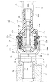
接続管32およびPCVバルブ40を中心とした要部断面図である図3を併せて参照すると、第2開口部31bに取り付けられる段付きの筒状の接続管32は、金属製、例えば鋼製の管材をプレス加工することにより形成され、接続管32の円筒状の小径部であって、雌ネジ部31cに螺合する雄ネジ部34aを有するネジ部34と、接続管32の円筒状の大径部であって後述するグロメット37が嵌合して係止される保持部36と、ネジ部34と保持部36との間に設けられ、かつネジ部34の外径および内径よりも大きく、保持部36の外径および内径よりも小さい外径および内径をそれぞれ有し、工具が係合する係合部35とを有する。
【0024】
工具により接続管32を第2開口部31bから連通路31にねじ込むことができるように、図4に図示されるように、係合部35の内周面には、横断面形状が多角形、この実施例では六角形である多角形部35aが形成され、多角形部35aと同一の横断面形状を有する工具が接続管32内に挿入されて、工具により接続管32を回転させることで、雄ネジ部34aが雌ネジ部31cに螺合して、接続管32がブラケット20に螺着される。また、係合部35の外周面の横断面形状も、多角形部35aの横断面形状と略相似の形状とされる。そして、ブラケット20に対する接続管32の螺着が完了した状態で、係合部35および保持部36は、ブラケット20の前面20aから前方に突出する突出部を形成する。
【0025】
また、保持部36の端部には、内方に突出して円周方向に延びる円環状の突条36aが形成され、この突条36aが、合成ゴム製のグロメット37の外周に形成された環状溝37aに係合することで、接続管32に対してグロメット37が係止される。
【0026】
このようにして、ブラケット20に接続管32が螺着され、さらにその接続管32にグロメット37が係止された状態で、PCVバルブ40が、グロメット37の内孔に圧入される。そして、そのグロメット37の弾性力により、PCVバルブ40が、グロメット37に対して、ひいては接続管32に対して保持される。それゆえ、PCVバルブ40は、発電機 14 のブリーザ室 21 寄りの部分 14a よりも前方で、発電機14の上方で、しかも近接した位置に、外部に露出した状態で接続管32に取り付けられる。しかも、PCVバルブ40は、一端部がネジ部34によりブラケット20に取り付けられた接続管32の他端部である保持部36に取り付けられるため、接続管32内においても、ねじ部34とPCVバルブ40との間に通路が存する。
【0027】
図3に図示されるように、PCVバルブ40は、フランジ41aを有する円筒状のボディ41と、フランジ42aを有する円筒状のカバー42と、円柱状の弁体43と、円筒状の圧縮コイルバネからなる制御バネ44とを備え、ボディ41、カバー42および弁体43は、いずれも合成樹脂、例えばポリブチレンテレフタレート樹脂(PBT)で形成され、制御バネ44はバネ鋼で形成される。
【0028】
そして、ボディ41は、接続ホース33がその外周に嵌合する嵌合部41bに設けられた流出孔41cと、該流出孔41cに連なる計量孔41dとを有し、カバー42は、グロメット37がその外周に嵌合する嵌合部42bに設けられた流入孔42cと、弁体43の後述する開閉弁部が制御バネ44のバネ力により着座する弁座42dとを有する。また、弁体43は、流入孔42cを開閉する円板状の開閉弁部43aと、計量孔41d内への進入の程度により、計量孔41dの周壁との間に形成される環状流路の流路面積を変更して、ブローバイガスの吸気系への還流量を制御する計量弁部43bとを有し、さらに制御バネ44は、ボディ41のバネ受け部41eと開閉弁部43aに隣接して弁体43に設けられたバネ受け部43cとの間で、その内側に計量弁部43bが配置されるように装着される。ボディ41とカバー42とは、両フランジ部41a,42aが超音波溶着されることで一体に結合されて、PCVバルブ40のハウジングを形成する。
【0029】
このような構成のPCVバルブ40により、流入孔42cおよび流出孔41cに等しい圧力が作用するときは、制御バネ44のバネ力により開閉弁部43aが弁座42dに着座して、流入孔42cを閉じる。そして、内燃機関Eのアイドル時や低負荷時等で、流出孔41cを介して弁体43に作用する吸気負圧が大きいときは、弁体43が制御バネ44のバネ力に抗して移動して、開閉弁部43aが流入孔42cを開くと同時に、計量弁部43bが計量孔41d内に大きく進入するため、前記環状流路の流路面積が小さくなって、ブローバイガスの吸気系への還流量が減少し、また内燃機関Eの高負荷時等で、流出孔41cを介して弁体43に作用する吸気負圧が小さいときは、弁体43が制御バネ44のバネ力に抗して移動して、開閉弁部43aが流入孔42cを開く一方で、計量弁部43bが計量孔41d内に進入する程度が小さくなるため、前記環状流路の流路面積が低負荷時等のそれに比べて大きくなって、ブローバイガスの吸気系への還流量が増加する。
このようにして、前記導入路、ブリーザ室21、PCVバルブ40および還流路30を主たる構成要素としてブローバイガス還元装置が構成される。
【0030】
次に、前述のように構成された実施例の作用および効果について説明する。
前記空気通路から動弁室を経てクランク室6に導入された空気により生じる流れで、クランク室6内のブローバイガスが前記導入路を経て、開口部26からブリーザ室21に流入し、ブリーザ室21内でブローバイガスに混入したオイルが分離される。そして、分離されたオイルは、回収孔27からチェーン室を経てオイルパン5に回収される。
【0031】
そして、ブリーザ室21内でオイルが分離されて、オイル混入量が少なくなったブローバイガスは、連通路31、接続管32および接続ホース33を主たる構成要素とする還流路30の第1開口部31aから、該還流路30を通って、PCVバルブ40により吸気負圧に基づいて流量制御された還流量で、吸気系に還流して、燃焼室内で燃焼される。
【0032】
発電機 14 に近接して配置されたPCVバルブ 40 は、発電機 14 が取り付けられたブラケット 14 に形成された連通路 31 を介して発電機 14 の背後に形成されたブリーザ室 21 に連通し、しかも発電機 14 のブリーザ室 21 寄りの部分 14a よりも前方で、かつ発電機 14 の上方に、外部に露出した状態で配置されるので、発電機 14 に対して、より前側でかつ上方において、ブリーザ室 21 の前方に位置する発電機 14 を避けた、脱着し易い位置に配置される。
この結果、PCVバルブ 40 は発電機 14 を避けた脱着し易い位置に配置されるので、発電機 14 に近接して配置されたPCVバルブ 40 の脱着が容易になって、PCVバルブ 40 のメンテナンスの作業性が向上する。
【0033】
ブラケット 20 において連通路 31 の第2開口部 31b が開口する前面 20a は、発電機 14 のブリーザ室 21 寄りの部分 14a よりも前方で、かつ発電機 14 の上方に位置し、PCVバルブ 40 が取り付けられる接続管 32 の前記突出部を構成する係合部35および保持部36がブリーザ室21を形成するブラケット20の前面 20aから突出している分、PCVバルブ40がブラケット20の前面20aよりも前方に離れて位置し、発電機 14 に対してより前側に位置することになるので、PCVバルブ40の脱着が容易になる。また、接続管32を使用するため、接続管32の一端部であるネジ部34が、ブリーザ室21において最適な位置に設けられたブローバイガスの導出口である第1開口部31aに連通される一方で、接続管32の他端部であるPCVバルブ40が取り付けられる保持部36を、PCVバルブ40に近接して配置される発電機14を避けて、PCVバルブ40の脱着がし易い位置に配置できる。
【0034】
その結果、次の効果が奏される。すなわち、PCVバルブ40はブリーザ室21を形成するブラケット20に取り付けられる接続管32の、ブラケット20の前面 20aから突出した保持部36に取り付けられるので、その脱着性が向上し、またブリーザ室21に連通する接続管32にPCVバルブ40が取り付けられるため、PCVバルブ40の位置が第1開口部31aを含む連通路31の位置の制約を受けることが少なくなって、PCVバルブ40の配置の自由度が増加するので、ブリーザ室21の室壁の周囲に位置する発電機14を避けて、PCVバルブ40の脱着がし易い位置を選択でき、この点でもその脱着性が向上し、PCVバルブ40のメンテナンスの作業性が向上する。
【0035】
PCVバルブ40のボディ41、カバー42および弁体43は合成樹脂製であるため、PCVバルブ40が軽量となる。しかしながら、ボディ41およびカバー42が合成樹脂であるため、PCVバルブ40自体をブリーザ室21を形成するブラケット20に強固に固定することはできない。しかしながら、取り付けられる接続管32は金属製であるため、その剛性が高く、ブリーザ室21を形成するブラケット20に接続管32は強固に取り付けられる。
【0036】
その結果、次の効果が奏される。すなわち、PCVバルブ40は、ボディ41、カバー42および弁体43が合成樹脂製であることから軽量化される。そして、金属製であることから高剛性であり、ブリーザ室21を形成するブラケット20に強固に取り付けられた接続管32を介して、合成樹脂製のボディ41およびカバー42を有するPCVバルブ40が、ブリーザ室21を形成するブラケット20に対して確実に保持される。
【0037】
接続管32をブリーザ室21のブラケット20に螺着する際、工具は接続管32の内側壁面の多角形部35aに係合されるので、接続管32の外側面で工具が係合するもののように、接続管32の周囲に工具を受け入れるための空間を確保する必要がない。
【0038】
その結果、次の効果が奏される。すなわち、接続管32は、ブリーザ室21を形成するブラケット20に対して、接続管32の内周面の多角形部35aに工具を係合させることにより螺着されるので、接続管32の周囲に工具を受け入れるための空間を確保する必要がなく、接続管32の周囲に配置される発電機14に近接して、ブラケット20における接続管32の螺着位置、すなわち第2開口部31bの位置を設定し、メンテナンスの作業の容易性を確保しつつ、PCVバルブ40をコンパクトに配置できる。
【0039】
PCVバルブ40が螺着された接続管32は、ブリーザ室21に比べて小さな内径の連通路31を介してブリーザ室21に連通するので、ブローバイガスがブリーザ室21から連通路31に流入するときは、この連通路31が絞りとして機能して、ブローバイガスに混入しているオイルは、連通路31を通過しにくくなり、結果としてブリーザ室21に留まる割合が高くなると共に、連通路31を通過するとき、連通路31の壁面に付着する。さらに、PCVバルブ40は接続管32を介して取り付けられるため、接続管32内の通路の分、ブリーザ室21からPCVバルブ40までの通路長が長くなり、この間でも接続管32の内面で形成される通路壁面にブローバイガス中のオイルが付着する。
【0040】
その結果、次の効果が奏される。すなわち、PCVバルブ40とブリーザ室21との間に設けられた連通路31が絞りとして機能すること、そしてブローバイガスに混入しているオイルが、連通路31の壁面に付着することにより分離されるので、PCVバルブ40に流入するブローバイガス中のオイルの量が少なくなって、吸気系でのオイルの付着やオイル消費量の増加を抑制できる。さらに、PCVバルブ40は接続管32を介して取り付けられるため、ブリーザ室21からPCVバルブ40までの通路長は、連通路31の通路長に加えて、接続管32内の通路の分長くなり、この間でもブローバイガス中のオイルが分離されるので、オイル分離機能がさらに向上する。
【0041】
ブリーザ室21の室壁の一部が冷却水ジャケット24を形成するシリンダ壁、および冷却水の導入通路25の通路壁25aで形成されていることから、内燃機関Eの暖機時には、冷却水ジャケット24および導入通路25を流れる冷却水によりブリーザ室21が効率よく暖められる。また、内燃機関Eの暖機後は、ラジエータで冷やされた冷却水が導入通路25を経てポンプ室に導入されるので、導入通路25および冷却水ジャケット24により、ブリーザ室21が高温となることが抑制される。
【0042】
その結果、次の効果が奏される。すなわち、内燃機関Eの暖機時には、冷却水ジャケット24および導入通路25の2つの加熱源となる冷却水によりブリーザ室21が効率よく暖められて、ブリーザ室21内での水蒸気の結露が防止されるので、回収されるオイルに水が混じることが防止されて、水の混入によるオイルの劣化を回避することができる。また、内燃機関Eの暖機後は、冷却水ジャケット24、およびラジエータからの冷却水が流れる導入通路25の2つの冷却源により、ブリーザ室21が高温となることが抑制されるので、オイルの分離が促進される。
【0043】
以下、前記実施例の一部の構成を変更した実施例について、変更した構成に関して説明する。
前記実施例では、PCVバルブ40は、発電機14に近接した位置に設けられたが、発電機14以外の補機に近接して設けられてもよく、またブリーザ室21がより吸気マニホルド10に近い位置に設けられる場合は、PCVバルブ40は、吸気マニホルド10に近接した位置に設けられる。また、接続管32は、ブラケット20に取り付けられたが、シリンダブロック1に取り付けられてもよい。
【0044】
PCVバルブ40は、補機である油圧ポンプ13と吸気マニホルド10との間に配置されてもよく、この場合にも、PCVバルブ40は接続管32に取り付けられるので、PCVバルブ40の脱着性は良好であり、PCVバルブ40のメンテナンスの作業性が向上する。
【0045】
接続管32には、ネジ部34と係合部35との代わりに圧入部を設けて、接続管がブラケット20等のブリーザ室21を形成する形成部材に圧入されるものであってもよく、その場合に、接続管を直管とすることのほかに、曲管とすることもでき、曲管とすることで、PCVバルブ40の配置の自由度が一層増加し、PCVバルブ40の脱着性が向上する。そして、接続管を曲管とする場合、該接続管を、吸気系でのブローバイガスの還流位置に近くなる方向に屈曲させることにより、例えば前記実施例のように、接続管32が吸気マニホルド10の右側方に位置して、吸気系でのブローバイガスの還流位置が吸気マニホルド10の左側方に位置する場合、接続管32を左方、すなわち吸気マニホルド10側に屈曲させることにより、接続ホース33の長さを短縮できるので、接続ホース33の取付け作業が容易になる。
【図面の簡単な説明】
【図1】 本願発明が適用される内燃機関の正面図である。
【図2】 図1のII−II線でのシリンダブロックおよびブラケットの断面図である。
【図3】 図2の要部断面図である。
【図4】 図3のIV−IV線断面図である。
【符号の説明】
1…シリンダブロック、2…シリンダヘッド、3…ヘッドカバー、4…ロアブロック、5…オイルパン、6…クランク室、7…シリンダ、8…チェーンカバー、
10…吸気マニホルド、11…サージタンク、12…スロットルボディ、13…油圧ポンプ、14…発電機、14a …部分、15…コンプレッサ、16…伝動ベルト、
20…ブラケット、20a …前面、21…ブリーザ室、22…第1凹部、23…第2凹部、24…冷却水ジャケット、25…導入通路、26…開口部、27…回収孔、
30…還流路、31…連通路、31a,31b…開口部、31c…雌ネジ部、32…接続管、33…接続ホース、34…ネジ部、35…係合部、35a…多角形部、36…保持部、37…グロメット、
40…PCVバルブ、41…ボディ、42…カバー、43…弁体、44…制御バネ、
E…内燃機関、B…ボルト、W1,W2…側壁、P…合わせ面。[0001]
BACKGROUND OF THE INVENTION
The present invention relates to an internal combustion engine mounted on a vehicle and including a PCV (Positive Crankcase Ventilation) valve in a blow-by gas reduction device .
[0002]
[Prior art]
2. Description of the Related Art Conventionally, in an internal combustion engine, a blow-by gas reduction device is provided to recirculate blow-by gas in a crankcase to an intake system and again suck it into a combustion chamber for combustion. In this blow-by gas reduction device, in order to prevent the oil mixed in the blow-by gas from flowing into the intake system and preventing the oil from adhering to the intake system and increasing the oil consumption, A breather chamber is provided to separate the oil in the gas, and a PCV valve is provided to adjust the amount of blow-by gas recirculated to the intake system according to the amount of blow-by gas generated according to the intake negative pressure. It is done.
[0003]
In a blow-by gas reduction device provided with a breather chamber, the PCV valve is usually attached to a forming member that forms the breather chamber directly or via a grommet. For example, in the technology disclosed in Japanese Patent No. 2888383, a breather chamber disposed between a surge tank and a cylinder block side wall that are close to each other includes a breather recess provided in the side wall of the cylinder block, and the breather recess. The PCV valve is attached to the lid plate via a grommet.
[0004]
[Problems to be solved by the invention]
By the way, in the case where the PCV valve is attached to the forming member forming the breather chamber in this way, since the PCV valve itself is small, the protruding amount from the outer surface of the forming member is small, and the breather chamber is attached to the cylinder block. In the formed internal combustion engine, like the breather chamber disclosed in the above publication, the breather chamber is disposed behind or to the side of the intake device (surge tank), and the PCV valve is also behind or to the side of the intake device. The PCV valve is often located behind or to the side of the auxiliary equipment attached to the cylinder block, and the PCV valve is not efficiently attached / detached during maintenance. The property was not good.
[0005]
The present invention has been made in view of such circumstances, and the invention according to
[0006]
[Means for Solving the Problems and Effects of the Invention]
The invention according to
[0007]
According to the first aspect of the present invention, the PCV valve disposed in the vicinity of the auxiliary machine has a breather chamber formed behind the auxiliary machine through a communication path formed in a bracket to which the auxiliary machine is attached. In addition, the breather is disposed in front of the part near the breather chamber of the auxiliary machine and above the auxiliary machine so as to be exposed to the outside. It is located at a position where it can be easily attached and detached, avoiding auxiliary equipment located in front of the chamber.
[0008]
As a result, the following effects are exhibited. That is, since the PCV valve is disposed at a position where it can be easily detached while avoiding the auxiliary machine , the PCV valve disposed near the auxiliary machine can be easily detached and the workability of the maintenance of the PCV valve is improved.
[0009]
According to a second aspect of the invention, Oite internal combustion agencies according to
[0010]
According to the second aspect of the present invention, the front surface of the bracket where the opening portion of the communication path opens is located in front of the auxiliary machine near the breather chamber and above the auxiliary machine, and the PCV valve is attached. Since the protruding portion of the connecting pipe protrudes forward from the front surface, the PCV valve is positioned forward from the front surface by the amount of the protruding portion, and is positioned further forward than the accessory. Therefore, it arrange | positions in the position which is easy to remove | desorb. In addition, since the connecting pipe connected to the communication path is used, the position of the PCV valve is less restricted by the position of the communication path.
[0011]
As a result, in addition to the effect of the first aspect of the invention, the following effect is achieved. That is, since the position of the PCV valve is less restricted by the position of the communication path formed in the bracket, the degree of freedom of the arrangement of the PCV valve is increased and its detachability is improved.
[0012]
According to a third aspect of the invention, Oite internal combustion agencies according to
[0013]
According to the third aspect of the present invention, since the connecting pipe is a curved pipe, the degree of freedom of the arrangement of the PCV valve is further increased as compared with a straight pipe, and the connecting pipe is blow-by in the intake system. Since it bends in the direction close to the gas recirculation position, the length of the connection hose can be shortened.
[0014]
As a result, in addition to the effects of the cited invention, the following effects are exhibited. That is, since the degree of freedom of arrangement of the PCV valve is further increased, the detachability of the PCV valve is improved, and the connecting hose can be easily attached.
[0015]
DETAILED DESCRIPTION OF THE INVENTION
Embodiments of the present invention will be described below with reference to FIGS.
Referring to FIG. 1 which is a front view of an internal combustion engine to which the present invention is applied, the internal combustion engine E is an overhead camshaft type in-line four-cylinder water-cooled four-cycle internal combustion engine mounted on a vehicle. A
[0016]
In this specification , “front / rear and left / right” means “front / rear and left / right” with reference to the vehicle unless otherwise specified.
[0017]
Four
[0018]
Referring also to FIG. 2, the
[0019]
The
[0020]
Further, a
[0021]
Further, the
[0022]
Hereinafter, the
[0023]
Referring also to FIG. 3, which is a cross-sectional view of the main part centering on the connecting
[0024]
As shown in FIG. 4, the inner circumferential surface of the engaging
[0025]
In addition, an
[0026]
Thus, the
[0027]
As shown in FIG. 3, the
[0028]
The
[0029]
When equal pressure acts on the
In this way, the blow-by gas reduction device is configured with the introduction path, the
[0030]
Next, operations and effects of the embodiment configured as described above will be described.
The blow-by gas in the
[0031]
The blow-by gas, in which the oil is separated in the
[0032]
As a result, the
[0033]
Front 20a is forward than the
[0034]
As a result, the following effects are exhibited. That is, since the
[0035]
Since the
[0036]
As a result, the following effects are exhibited. That is, the
[0037]
When the connecting
[0038]
As a result, the following effects are exhibited. That is, the connecting
[0039]
Since the connecting
[0040]
As a result, the following effects are exhibited. That is, the
[0041]
Since a part of the chamber wall of the
[0042]
As a result, the following effects are exhibited. That is, when the internal combustion engine E is warmed up, the
[0043]
Hereinafter, an example in which a part of the configuration of the embodiment is changed will be described with respect to the changed configuration.
In the above embodiment, the
[0044]
The
[0045]
The connecting
[Brief description of the drawings]
FIG. 1 is a front view of an internal combustion engine to which the present invention is applied.
FIG. 2 is a cross-sectional view of a cylinder block and a bracket taken along line II-II in FIG.
3 is a cross-sectional view of the main part of FIG. 2;
4 is a cross-sectional view taken along the line IV-IV in FIG. 3;
[Explanation of symbols]
DESCRIPTION OF
10 ... intake manifold, 11 ... surge tank, 12 ... throttle body, 13 ... hydraulic pump, 14 ... generator, 14a ... part, 15 ... compressor, 16 ... transmission belt,
20 ... Bracket, 20a ... Front, 21 ... Breather chamber, 22 ... First recess, 23 ... Second recess, 24 ... Cooling water jacket, 25 ... Introduction passage, 26 ... Opening, 27 ... Collection hole,
30 ... Return path, 31 ... Communication path, 31a, 31b ... Opening, 31c ... Female thread part, 32 ... Connection pipe, 33 ... Connection hose, 34 ... Screw part, 35 ... Engagement part, 35a ... Polygon part, 36 ... holding part, 37 ... grommet,
40 ... PCV valve, 41 ... Body, 42 ... Cover, 43 ... Valve, 44 ... Control spring,
E ... Internal combustion engine, B ... Bolt, W1, W2 ... Side wall, P ... Mating surface.
Claims (3)
前記ブリーザ室は、前記補機の背後において前記シリンダブロックと前記ブラケットとによりに形成され、前記還流路は前記ブラケットに形成されて前記ブリーザ室に連通する連通路を含み、前記連通路を介して前記ブリーザ室に連通する前記PCVバルブは、前記補機の前記ブリーザ室寄りの部分よりも前方で、かつ前記補機の上方に、外部に露出した状態で、前記補機に近接して配置されていることを特徴とする内燃機関。 An internal combustion engine mounted on a vehicle, provided in an accessory bracket to which an accessory is attached, a cylinder block that forms a breather chamber, and a return path that guides blow-by gas from the breather chamber to the intake system In an internal combustion engine comprising a PCV valve,
The breather chamber is formed by the cylinder block and the bracket behind the auxiliary machine, and the return path includes a communication path formed in the bracket and communicating with the breather chamber, through the communication path. The PCV valve communicating with the breather chamber is disposed in front of the portion near the breather chamber of the auxiliary machine and above the auxiliary machine in a state exposed to the outside and in the vicinity of the auxiliary machine. An internal combustion engine characterized by that .
Priority Applications (1)
| Application Number | Priority Date | Filing Date | Title |
|---|---|---|---|
| JP2003141012A JP4079828B2 (en) | 2003-05-19 | 2003-05-19 | Internal combustion engine with a PCV valve |
Applications Claiming Priority (1)
| Application Number | Priority Date | Filing Date | Title |
|---|---|---|---|
| JP2003141012A JP4079828B2 (en) | 2003-05-19 | 2003-05-19 | Internal combustion engine with a PCV valve |
Related Parent Applications (1)
| Application Number | Title | Priority Date | Filing Date |
|---|---|---|---|
| JP2000326062A Division JP3451397B2 (en) | 2000-10-25 | 2000-10-25 | Mounting structure of PCV valve for internal combustion engine |
Publications (3)
| Publication Number | Publication Date |
|---|---|
| JP2003301709A JP2003301709A (en) | 2003-10-24 |
| JP2003301709A5 JP2003301709A5 (en) | 2005-10-13 |
| JP4079828B2 true JP4079828B2 (en) | 2008-04-23 |
Family
ID=29398349
Family Applications (1)
| Application Number | Title | Priority Date | Filing Date |
|---|---|---|---|
| JP2003141012A Expired - Fee Related JP4079828B2 (en) | 2003-05-19 | 2003-05-19 | Internal combustion engine with a PCV valve |
Country Status (1)
| Country | Link |
|---|---|
| JP (1) | JP4079828B2 (en) |
Families Citing this family (6)
| Publication number | Priority date | Publication date | Assignee | Title |
|---|---|---|---|---|
| JP4683486B2 (en) * | 2006-02-21 | 2011-05-18 | 本田技研工業株式会社 | Engine with breather device |
| JP4946856B2 (en) * | 2007-12-21 | 2012-06-06 | トヨタ自動車株式会社 | Oil separator |
| JP5002037B2 (en) * | 2010-05-12 | 2012-08-15 | 本田技研工業株式会社 | Blowby gas recirculation system |
| US8919329B2 (en) | 2011-11-07 | 2014-12-30 | Ford Global Technologies, Llc | PCV system having internal routing |
| JP6135102B2 (en) * | 2012-11-22 | 2017-05-31 | アイシン精機株式会社 | Blow-by gas reduction device |
| JP5983350B2 (en) * | 2012-11-22 | 2016-08-31 | アイシン精機株式会社 | PCV valve mounting structure |
-
2003
- 2003-05-19 JP JP2003141012A patent/JP4079828B2/en not_active Expired - Fee Related
Also Published As
| Publication number | Publication date |
|---|---|
| JP2003301709A (en) | 2003-10-24 |
Similar Documents
| Publication | Publication Date | Title |
|---|---|---|
| EP2149697B1 (en) | Air intake manifold for internal combustion engine | |
| CA2198168C (en) | Engine breather device with cooling baffle | |
| US20150275830A1 (en) | Supercharging system for engine | |
| EP1447533A1 (en) | Blowby gas circulating apparatus for an internal combustion engine | |
| JP6174348B2 (en) | Internal combustion engine for vehicles | |
| US7556013B2 (en) | Cover structure for a cooling system component of an internal combustion engine, and engine incorporating same | |
| JP4079828B2 (en) | Internal combustion engine with a PCV valve | |
| JP5009271B2 (en) | Internal combustion engine | |
| CN109026322B (en) | Cooling oil passage structure of engine | |
| JP3451397B2 (en) | Mounting structure of PCV valve for internal combustion engine | |
| JP2007085301A (en) | Multicylinder engine | |
| CN109072836B (en) | Engine device | |
| US11280233B2 (en) | Ventilator-equipped engine | |
| JP4603405B2 (en) | Saddle riding vehicle | |
| JP3680965B2 (en) | Intake pipe of internal combustion engine with carburetor | |
| JP4042951B2 (en) | Blow-by gas reduction device | |
| US7571704B2 (en) | Internal combustion engine provided with electrical equipment holder | |
| JP2004270457A (en) | Cylinder head for internal combustion engine | |
| JP2007085215A (en) | Multicylinder engine | |
| JPH10141154A (en) | Intake manifold of engine | |
| US10871137B2 (en) | Fuel supply device for internal combustion engine | |
| US20040216726A1 (en) | Exhaust gas purifying device for engines | |
| US7665449B2 (en) | V-type engine | |
| CN109578133B (en) | Intake device for internal combustion engine for vehicle | |
| JP4390218B2 (en) | Engine fuel injection device for motorcycles |
Legal Events
| Date | Code | Title | Description |
|---|---|---|---|
| A521 | Written amendment |
Free format text: JAPANESE INTERMEDIATE CODE: A523 Effective date: 20050608 |
|
| A621 | Written request for application examination |
Free format text: JAPANESE INTERMEDIATE CODE: A621 Effective date: 20050608 |
|
| TRDD | Decision of grant or rejection written | ||
| A01 | Written decision to grant a patent or to grant a registration (utility model) |
Free format text: JAPANESE INTERMEDIATE CODE: A01 Effective date: 20080205 |
|
| A61 | First payment of annual fees (during grant procedure) |
Free format text: JAPANESE INTERMEDIATE CODE: A61 Effective date: 20080205 |
|
| FPAY | Renewal fee payment (event date is renewal date of database) |
Free format text: PAYMENT UNTIL: 20110215 Year of fee payment: 3 |
|
| R150 | Certificate of patent or registration of utility model |
Free format text: JAPANESE INTERMEDIATE CODE: R150 |
|
| FPAY | Renewal fee payment (event date is renewal date of database) |
Free format text: PAYMENT UNTIL: 20110215 Year of fee payment: 3 |
|
| FPAY | Renewal fee payment (event date is renewal date of database) |
Free format text: PAYMENT UNTIL: 20120215 Year of fee payment: 4 |
|
| FPAY | Renewal fee payment (event date is renewal date of database) |
Free format text: PAYMENT UNTIL: 20120215 Year of fee payment: 4 |
|
| FPAY | Renewal fee payment (event date is renewal date of database) |
Free format text: PAYMENT UNTIL: 20130215 Year of fee payment: 5 |
|
| FPAY | Renewal fee payment (event date is renewal date of database) |
Free format text: PAYMENT UNTIL: 20130215 Year of fee payment: 5 |
|
| FPAY | Renewal fee payment (event date is renewal date of database) |
Free format text: PAYMENT UNTIL: 20140215 Year of fee payment: 6 |
|
| LAPS | Cancellation because of no payment of annual fees |