EP3263807A1 - Schliesseinrichtung, insbesondere schliesszylinder - Google Patents
Schliesseinrichtung, insbesondere schliesszylinder Download PDFInfo
- Publication number
- EP3263807A1 EP3263807A1 EP17176003.6A EP17176003A EP3263807A1 EP 3263807 A1 EP3263807 A1 EP 3263807A1 EP 17176003 A EP17176003 A EP 17176003A EP 3263807 A1 EP3263807 A1 EP 3263807A1
- Authority
- EP
- European Patent Office
- Prior art keywords
- positive
- core
- locking
- cam
- locking element
- Prior art date
- Legal status (The legal status is an assumption and is not a legal conclusion. Google has not performed a legal analysis and makes no representation as to the accuracy of the status listed.)
- Granted
Links
Images

Classifications
-
- E—FIXED CONSTRUCTIONS
- E05—LOCKS; KEYS; WINDOW OR DOOR FITTINGS; SAFES
- E05B—LOCKS; ACCESSORIES THEREFOR; HANDCUFFS
- E05B17/00—Accessories in connection with locks
- E05B17/04—Devices for coupling the turning cylinder of a single or a double cylinder lock with the bolt operating member
-
- E—FIXED CONSTRUCTIONS
- E05—LOCKS; KEYS; WINDOW OR DOOR FITTINGS; SAFES
- E05B—LOCKS; ACCESSORIES THEREFOR; HANDCUFFS
- E05B15/00—Other details of locks; Parts for engagement by bolts of fastening devices
- E05B15/004—Lost motion connections
-
- E—FIXED CONSTRUCTIONS
- E05—LOCKS; KEYS; WINDOW OR DOOR FITTINGS; SAFES
- E05B—LOCKS; ACCESSORIES THEREFOR; HANDCUFFS
- E05B17/00—Accessories in connection with locks
- E05B17/04—Devices for coupling the turning cylinder of a single or a double cylinder lock with the bolt operating member
- E05B17/047—Devices for coupling the turning cylinder of a single or a double cylinder lock with the bolt operating member with rotating output elements forming part of cylinder locks, e.g. locking cams of double cylinder locks
-
- E—FIXED CONSTRUCTIONS
- E05—LOCKS; KEYS; WINDOW OR DOOR FITTINGS; SAFES
- E05B—LOCKS; ACCESSORIES THEREFOR; HANDCUFFS
- E05B47/00—Operating or controlling locks or other fastening devices by electric or magnetic means
- E05B47/06—Controlling mechanically-operated bolts by electro-magnetically-operated detents
- E05B47/0611—Cylinder locks with electromagnetic control
-
- E—FIXED CONSTRUCTIONS
- E05—LOCKS; KEYS; WINDOW OR DOOR FITTINGS; SAFES
- E05B—LOCKS; ACCESSORIES THEREFOR; HANDCUFFS
- E05B47/00—Operating or controlling locks or other fastening devices by electric or magnetic means
- E05B47/06—Controlling mechanically-operated bolts by electro-magnetically-operated detents
- E05B47/0611—Cylinder locks with electromagnetic control
- E05B47/0638—Cylinder locks with electromagnetic control by disconnecting the rotor
- E05B47/0646—Cylinder locks with electromagnetic control by disconnecting the rotor radially
- E05B47/0649—Cylinder locks with electromagnetic control by disconnecting the rotor radially with a rectilinearly moveable coupling element
-
- E—FIXED CONSTRUCTIONS
- E05—LOCKS; KEYS; WINDOW OR DOOR FITTINGS; SAFES
- E05B—LOCKS; ACCESSORIES THEREFOR; HANDCUFFS
- E05B9/00—Lock casings or latch-mechanism casings ; Fastening locks or fasteners or parts thereof to the wing
- E05B9/10—Coupling devices for the two halves of double cylinder locks, e.g. devices for coupling the rotor with the locking cam
-
- E—FIXED CONSTRUCTIONS
- E05—LOCKS; KEYS; WINDOW OR DOOR FITTINGS; SAFES
- E05B—LOCKS; ACCESSORIES THEREFOR; HANDCUFFS
- E05B9/00—Lock casings or latch-mechanism casings ; Fastening locks or fasteners or parts thereof to the wing
- E05B9/04—Casings of cylinder locks
- E05B2009/047—Means for returning cylinder locks to their neutral position
Definitions
- the invention relates to a locking device, in particular lock cylinder, with a core mounted in a housing, with a locking mechanism for generating a positive connection between the housing and the core, with a cam and with a clutch for selectively generating or solving a positive connection of the cam with the core and means for introducing a torque into the core, the coupling having a positive engagement element penetrating into the movement region of the core and the locking bit to produce positive locking.
- Such a closing device is for example from the EP 1 079 050 A1 known.
- the coupling can only be separated from one side of the closing device.
- the lock bit can be moved from the other side.
- an anti-panic cylinder has become known in which a locking lug can be moved from an outside of a door via a key and from the inside by operating a door handle.
- the cylinder has a return mechanism which, in a basic position of the cylinder, returns the locking lug to a predetermined position.
- the cam In anti-panic locking devices, however, it is necessary that in a non-actuation corresponding basic position of the lock cylinder, the cam has a freewheeling function, so that the cam can be moved without activation of the locking mechanism.
- the invention is based on the problem, so to form a locking device of the type mentioned so that a freewheeling function of the cam in the basic position is reliably guaranteed.
- the optional generation or solution of the positive connection of the coupling is dependent on the angular range of the core.
- the cam can be driven by a correspondingly wide rotation of the core.
- the clutch also ensures a freewheel over at least the angular range.
- the cam can be driven independently of the core to produce the anti-panic function.
- the means for introducing a torque are usually a knob or a closing channel for insertion of a key in common locking devices.
- the limitation of the positive locking on the intended angular range designed according to another advantageous embodiment of the invention is particularly simple if the coupling has means for removing the positive locking element from the range of motion of the core or the cam after the intended angle range.
- the means have a arranged in a fixed component pocket for receiving the positive locking element.
- the positive locking element can dive into the pocket after the intended angular range and solve the positive connection between the core and cam.
- the positive-locking element can protrude radially out of the guide and thus produce a positive connection with the respective other component of the core or of the locking bit.
- the interlocking element is movable back into the guide depending on the angular range, the positive connection between the core and cam can be easily solved.
- the freewheel of the cam can be easily ensured in accordance with another advantageous embodiment of the invention in the basic state of the locking device when the interlocking element is arranged outside the range of movement of the control cam in a key withdrawal position of the locking mechanism.
- the positive connection in the basic state of the closing device for a drive on the cam is permanently released, so that a blockage of a lock is avoided by the locking device located in the ground state.
- the generation of the freewheel for the intended angular range designed in accordance with another advantageous embodiment of the invention structurally particularly simple if the leadership of the opposing component of the cam or the core extending over the intended angular range, limited by the control cam groove for receiving the from Guide protruding positive locking element has.
- the positive connection is produced in one direction of rotation, as long as the positive locking element protrudes from the guide, but solved in the opposite direction of rotation of the positive locking over the intended angular range, because the positive locking element moves in the groove.
- a change of the positive connection and the freewheel over several revolutions of the core can be easily generated according to another advantageous embodiment of the invention, if between two control cam a second groove for receiving the positive locking element is arranged and that the second groove at least over the angular range of the pocket in the fixed Component extends. This ensures that one freewheel is generated over one revolution of the core after every complete revolution or every second complete revolution of the core.
- the mode of action also applies in both directions.
- the locking device can be produced in accordance with another advantageous embodiment of the invention particularly cost-effective, if the positive locking element is designed as a ball.
- control of the positive locking element in the radial direction is particularly simple according to another advantageous embodiment of the invention, if at least one the components of the pocket, the groove and the second groove have at their ends ramps for moving the positive locking element in the guide.
- the closing device is structurally particularly simple if a ring element connected to the core has the guide, a cam bit connected to the cam has the control cam and / or a housing arm connected to the housing has the pocket.
- FIG. 1 shows a trained as a lock cylinder closing device with a housing 1 and with a rotatably mounted in the housing 1 core 2. Furthermore, the locking device has a mounted in the housing 1 second core 3. The two cores 2, 3 allow unlocking of the locking device of the two End faces of the housing 1. Between the cores 2, 3, a cam 4 is rotatably mounted in the housing 1. A clutch 5 is disposed between the core 2 and the cam 4 and has a non-rotatably connected to the core 2 clutch plate 6. A driver 7 connects the second core 3 with the clutch plate 6 of the clutch 5. The driver 7 is a sliding bolt. 8 controlled, which is displaceable over a key inserted into a closing channel 9 of a core 2 key.
- the sliding bolt 8 About the position of the sliding bolt 8 a positive connection between the second core 3 and the clutch plate 6 is released or generated.
- a non-rotatably connected to the cam 4 lock bit sleeve 10 limits the clutch 5 radially outward.
- a ring member 11 of the clutch plate 6 Radially within the lock bit sleeve 10, a ring member 11 of the clutch plate 6 is arranged.
- a rotatably connected to the housing 1 housing arm 12 is disposed radially within the ring member 11.
- the locking device has an electronic locking mechanism 13 for selectively blocking or releasing the movement of the core 2 in the housing 1.
- FIG. 2 shows a sectional view through the coupling 5 with adjacent areas of the locking device.
- the ring element 11 has a radially oriented guide 14 for a positive-locking element 15 designed as a ball or as a cylinder.
- the positive locking element 15 is rotatably connected to the ring member 11 and is in the position shown partially in front of the guide 14 radially inwardly.
- the lock bit sleeve 10 has one of two radially inwardly facing control cam 16, 17 limited groove 18 and a second groove 19.
- the groove 18 extends over a large angular range of about 300 °.
- the housing extension 12 has a pocket 20.
- the pocket 20 and the second groove 19 extend approximately over the same, relative to the angular range of the groove 18 small angle range of about 50 °.
- the groove 18, the second groove 19 and the pocket 20 are designed expiring flat at their ends and thus each form ramps to facilitate the movement of the positive locking element 15 in the radial direction.
- FIG. 2 shows the coupling 5 in a position in which the positive-locking element 15 is located in the region of the pocket 20 of the housing arm 12. In this position, the positive locking element is completely outside the ranges of movement of the control cam 16, 17. Thus, the cam 4 can be rotated freely by manual drive in both directions without the locking mechanism 13 of the core 2 can block this movement.
- the position of the ring element 11 indicates a key withdrawal position and thus a ground state of the locking device.
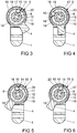
- the positive locking element 15 is moved out of the pocket 20 and passes depending on the position of the cam 4, for example, in the second groove 19 of the cam bit 10. This allows the cam 4 by rotation of the core 2 to drive at least one revolution until the interlocking element 15 again falls into the pocket 20 of the housing arm 12. By further rotation of the ring member 11, however, the positive locking element 15 infiltrates the control cam 17 and enters the groove 18. This position is in FIG. 3 shown. Starting from this position, in a further rotation of the core 2, a movement of the positive-locking element 15 in the groove 18, without the lock bit 4 is taken.
- the positive locking element 15 comes against the other control cam 16 and generates a new positive connection.
- This position is in FIG. 4 shown.
- the positive locking element 15 is partially in the guide 14 of the ring element 11 connected to the core 2 and partially in the groove 18 of the lock bit sleeve 10 immediately before one of the control cam 16.
- the positive locking element 15 is supported in this position by the housing bracket 12. In a direction of rotation of the core 2 and thus the ring member 11 in a clockwise direction, the cam bit 10 and thus the cam 4 is taken.
- a lock equipped with the locking device can be closed with it.
- the form-locking element 15 can be moved over the entire angular range of the groove 18 to the other control cam 17, without the cam 4 is rotated.
- the cam 4 can be rotated over the angular range without the locking mechanism 13 obstructing the movement of the core 2.
- the core 2 can be rotated further in a clockwise direction.
- the positive locking element 15 infiltrates the one control cam 16 and gets back into the second groove 19, as in FIG. 6 is shown.
Landscapes
- Physics & Mathematics (AREA)
- Electromagnetism (AREA)
- Engineering & Computer Science (AREA)
- Mechanical Engineering (AREA)
- Lock And Its Accessories (AREA)
Abstract
Description
- Die Erfindung betrifft eine Schließeinrichtung, insbesondere Schließzylinder, mit einem in einem Gehäuse gelagerten Kern, mit einem Sperrmechanismus zur Erzeugung eines Formschlusses zwischen dem Gehäuse und dem Kern, mit einem Schließbart und mit einer Kupplung zur wahlweisen Erzeugung oder Lösung eines Formschlusses des Schließbartes mit dem Kern und mit Mitteln zur Einleitung eines Drehmoments in den Kern, wobei die Kupplung ein in den Bewegungsbereich des Kerns und des Schließbartes eindringendes Formschlusselement zur Erzeugung eines Formschlusses aufweist.
- Eine solche Schließeinrichtung ist beispielsweise aus der
EP 1 079 050 A1 bekannt. Bei dieser Schließeinrichtung lässt sich die Kupplung nur von einer Seite der Schließeinrichtung trennen. Damit kann, wenn der Sperrmechanismus eine Seite blockiert, der Schließbart von der anderen Seite bewegt werden. - Aus der
DE 10 2009 052 663 A1 ist ein Anti-Panik-Zylinder bekannt geworden, bei dem eine Schließnase von einer Außenseite einer Tür über einen Schlüssel und von der Innenseite durch Betätigen eines Türdrückers bewegt werden kann. Der Zylinder hat einen Rückstellmechanismus, welcher in einer Grundstellung des Zylinders die Schließnase in eine vorbestimmte Position zurückdreht. - Bei Anti-Panik Schließeinrichtungen ist es jedoch erforderlich, dass in einer der Nichtbetätigung entsprechenden Grundstellung des Schließzylinders der Schließbart eine Freilauffunktion aufweist, so dass der Schließbart ohne Ansteuerung des Sperrmechanismus bewegt werden kann.
- Der Erfindung liegt das Problem zugrunde, eine Schließeinrichtung der eingangs genannten Art so weiter zu bilden, dass eine Freilauffunktion des Schließbartes in Grundstellung zuverlässig gewährleistet ist.
- Dieses Problem wird erfindungsgemäß dadurch gelöst, dass der Formschluss der Kupplung auf einen vorgesehenen Winkelbereich begrenzt ist und dass die Kupplung über den vorgesehenen Winkelbereich einen Freilauf hat.
- Durch diese Gestaltung ist die wahlweise Erzeugung oder Lösung des Formschlusses der Kupplung abhängig von dem Winkelbereich des Kerns. Damit lässt sich der Schließbart durch eine entsprechend weite Drehung des Kerns antreiben. Jedoch gewährleistet die Kupplung auch einen Freilauf über zumindest den Winkelbereich. Damit kann der Schließbart unabhängig von dem Kern angetrieben werden, um die Anti-Panik Funktion zu erzeugen. Die Mittel zur Einleitung eines Drehmoments sind bei gängigen Schließeinrichtungen meist ein Knauf oder ein Schließkanal zum Einführen eines Schlüssels.
- Die Begrenzung des Formschlusses auf den vorgesehenen Winkelbereich gestaltet sich gemäß einer anderen vorteilhaften Weiterbildung der Erfindung besonders einfach, wenn die Kupplung Mittel zur Entfernung des Formschlusselementes aus dem Bewegungsbereich des Kerns oder des Schließbartes nach dem vorgesehenen Winkelbereich hat.
- Zur Vereinfachung der Lösung des Formschlusses nach dem vorgesehenen Winkelbereich trägt es gemäß einer anderen vorteilhaften Weiterbildung der Erfindung bei, wenn die Mittel eine in einem feststehenden Bauteil angeordnete Tasche zur Aufnahme des Formschlusselementes haben. Durch diese Gestaltung kann das Formschlusselement nach dem vorgesehenen Winkelbereich in die Tasche abtauchen und den Formschluss zwischen Kern und Schließbart lösen.
- Die Lösung oder Erzeugung des Formschlusses zwischen dem Kern und dem Schließbart in Abhängigkeit von dem Winkelbereich gestaltet sich gemäß einer anderen vorteilhaften Weiterbildung der Erfindung konstruktiv besonders einfach, wenn der Kern oder der Schließbart eine Führung für das Formschlusselement aufweist, wobei das Formschlusselement in Drehrichtung einen Formschluss in der Führung hat und in Abhängigkeit von dem Winkelbereich radial nach innen oder nach außen über die Begrenzung der Führung bewegbar ist. Durch diese Gestaltung kann das Formschlusselement aus der Führung radial herausragen und damit einen Formschluss mit dem jeweils anderen Bauteil des Kerns oder des Schließbartes erzeugen. Da jedoch das Formschlusselement in Abhängigkeit von dem Winkelbereich in die Führung zurückbewegbar ist, kann der Formschluss zwischen Kern und Schließbart einfach gelöst werden.
- Die Erzeugung des Formschlusses zwischen Schließbart und Kern gestaltet sich gemäß einer anderen vorteilhaften Weiterbildung der Erfindung konstruktiv besonders einfach, wenn das der Führung gegenüberstehende Bauteil des Schließbartes oder des Kerns zumindest einen in den Bewegungsbereich des aus der Führung hervorstehenden Formschlusselementes hineinragenden Steuernocken hat.
- Der Freilauf des Schließbartes lässt sich gemäß einer anderen vorteilhaften Weiterbildung der Erfindung im Grundzustand der Schließeinrichtung einfach sicherstellen, wenn in einer Schlüsselabzugsstellung des Sperrmechanismus das Formschlusselement außerhalb des Bewegungsbereichs des Steuernockens angeordnet ist. Durch diese Gestaltung ist der Formschluss im Grundzustand der Schließeinrichtung für einen Antrieb am Schließbart dauerhaft gelöst, so dass eine Blockierung eines Schlosses durch die im Grundzustand befindliche Schließeinrichtung vermieden ist.
- Die Erzeugung des Freilaufes für den vorgesehenen Winkelbereich gestaltet sich gemäß einer anderen vorteilhaften Weiterbildung der Erfindung konstruktiv besonders einfach, wenn das der Führung gegenüberstehende Bauteil des Schließbartes oder des Kerns eine sich über den vorgesehenen Winkelbereich erstreckende, von dem Steuernocken begrenzte Nut zur Aufnahme des aus der Führung hervorstehenden Formschlusselementes hat. Durch diese Gestaltung ist in der einen Drehrichtung der Formschluss erzeugt, solange das Formschlusselement aus der Führung hervorsteht, jedoch in der entgegen gesetzten Drehrichtung der Formschluss über den vorgesehenen Winkelbereich gelöst, weil sich das Formschlusselement in der Nut bewegt.
- Ein Abwechseln des Formschlusses und des Freilaufes über mehrere Umdrehungen des Kerns lässt sich gemäß einer anderen vorteilhaften Weiterbildung der Erfindung einfach erzeugen, wenn zwischen zwei Steuernocken eine Zweitnut zur Aufnahme des Formschlusselementes angeordnet ist und dass sich die Zweitnut zumindest über den Winkelbereich der Tasche in dem feststehenden Bauteil erstreckt. Hierdurch lässt sich gewährleisten, dass nach jeder vollständigen Umdrehung oder jeder zweiten vollständigen Umdrehung des Kerns ein Freilauf über eine Umdrehung des Kerns erzeugt ist. Die Wirkungsweise gilt zudem in beide Drehrichtungen.
- Die Schließeinrichtung lässt sich gemäß einer anderen vorteilhaften Weiterbildung der Erfindung besonders kostengünstig fertigen, wenn das Formschlusselement als Kugel ausgebildet ist.
- Die Steuerung des Formschlusselementes in radialer Richtung gestaltet sich gemäß einer anderen vorteilhaften Weiterbildung der Erfindung besonders einfach, wenn zumindest eines der Bauteile der Tasche, der Nut und der Zweitnut an ihren Enden Rampen zur Bewegung des Formschlusselementes in die Führung aufweisen.
- Die Schließeinrichtung gestaltet sich gemäß einer anderen vorteilhaften Weiterbildung der Erfindung konstruktiv besonders einfach, wenn ein mit dem Kern verbundenes Ringelement die Führung, ein mit dem Schließbart verbundene Schließbarthülse den Steuernocken und/oder ein mit dem Gehäuse verbundener Gehäuseausleger die Tasche aufweist.
- Die Erfindung lässt zahlreiche Ausführungsformen zu. Zur weiteren Verdeutlichung ihres Grundprinzips ist eine davon in der Zeichnung dargestellt und wird nachfolgend beschrieben. Diese zeigt in
- Fig. 1
- einen Längsschnitt durch eine erfindungsgemäße Schließeinrichtung,
- Fig. 2
- eine Schnittdarstellung durch die Schließeinrichtung aus
Figur 1 ent-lang der Linie II - II, im Bereich einer Kupplung, - Fig. 3 - 6
- die Kupplung aus
Figur 2 in weiteren Stellungen. -
Figur 1 zeigt eine als Schließzylinder ausgebildete Schließeinrichtung mit einem Gehäuse 1 und mit einem in dem Gehäuse 1 drehbar gelagerten Kern 2. Weiterhin hat die Schließeinrichtung einen in dem Gehäuse 1 gelagerten zweiten Kern 3. Die beiden Kerne 2, 3 ermöglichen eine Entriegelung der Schließeinrichtung von den beiden Stirnseiten des Gehäuses 1. Zwischen den Kernen 2, 3 ist ein Schließbart 4 drehbar in dem Gehäuse 1 gelagert. Eine Kupplung 5 ist zwischen dem einem Kern 2 und dem Schließbart 4 angeordnet und hat eine mit dem Kern 2 drehfest verbundene Kupplungsplatte 6. Ein Mitnehmer 7 verbindet den zweiten Kern 3 mit der Kupplungsplatte 6 der Kupplung 5. Der Mitnehmer 7 wird über einen Schiebebolzen 8 gesteuert, welcher über einen in einen Schließkanal 9 des einen Kerns 2 eingeführten Schlüssels verschiebbar ist. Über die Stellung des Schiebebolzens 8 wird ein Formschluss zwischen dem zweiten Kern 3 und der Kupplungsplatte 6 gelöst oder erzeugt. Eine drehfest mit dem Schließbart 4 verbundene Schließbarthülse 10 begrenzt die Kupplung 5 radial nach außen. Radial innerhalb der Schließbarthülse 10 ist ein Ringelement 11 der Kupplungsplatte 6 angeordnet. Ein drehfest mit dem Gehäuse 1 verbundener Gehäuseausleger 12 ist radial innerhalb des Ringelementes 11 angeordnet. Weiterhin hat die Schließeinrichtung einen elektronischen Sperrmechanismus 13 zur wahlweisen Blockierung oder Freigabe der Bewegung des Kerns 2 in dem Gehäuse 1. -
Figur 2 zeigt eine Schnittdarstellung durch die Kupplung 5 mit angrenzenden Bereichen der Schließeinrichtung. Hierbei ist zu erkennen, dass das Ringelement 11 eine radial ausgerichtete Führung 14 für ein als Kugel oder als Zylinder ausgebildetes Formschlusselement 15 hat. Das Formschlusselement 15 ist drehfest mit dem Ringelement 11 verbunden und steht in der dargestellten Stellung teilweise aus der Führung 14 radial nach innen vor. Die Schließbarthülse 10 hat eine von zwei radial nach innen weisenden Steuernocken 16, 17 begrenzte Nut 18 und eine Zweitnut 19. Die Nut 18 erstreckt sich über einen großen Winkelbereich von etwa 300°. Der Gehäuseausleger 12 weist eine Tasche 20 auf. Die Tasche 20 und die Zweitnut 19 erstrecken sich ungefähr über den gleichen, relativ zum Winkelbereich der Nut 18 kleinen Winkelbereich von etwa 50°. Die Nut 18, die Zweitnut 19 und die Tasche 20 sind an ihren Enden flach auslaufend gestaltet und bilden damit jeweils Rampen zur Erleichterung der Bewegung des Formschlusselementes 15 in radialer Richtung. -
Figur 2 zeigt die Kupplung 5 in einer Stellung, in der das Formschlusselement 15 im Bereich der Tasche 20 des Gehäuseauslegers 12 liegt. In dieser Stellung befindet sich das Formschlusselement vollständig außerhalb der Bewegungsbereiche der Steuernocken 16, 17. Damit kann der Schließbart 4 durch manuellen Antrieb in beide Drehrichtungen ungehindert verdreht werden, ohne dass der Sperrmechanismus 13 des Kerns 2 diese Bewegung blockieren kann. Die Stellung des Ringelementes 11 kennzeichnet eine Schlüsselabzugsstellung und damit einem Grundzustand der Schließeinrichtung. - Bei einem Antrieb des Kerns 2 und damit des Ringelementes 11 im Uhrzeigersinn oder gegen den Uhrzeigersinn wird jedoch das Formschlusselement 15 aus der Tasche 20 herausbewegt und gelangt je nach Stellung des Schließbartes 4 beispielsweise in die Zweitnut 19 der Schließbarthülse 10. Damit lässt sich der Schließbart 4 durch Drehung des Kerns 2 um zumindest eine Umdrehung antreiben, bis das Formschlusselement 15 erneut in die Tasche 20 des Gehäuseauslegers 12 fällt. Durch weitere Drehung des Ringelementes 11 unterwandert das Formschlusselement 15 jedoch den Steuernocken 17 und gelangt in die Nut 18. Diese Stellung ist in
Figur 3 dargestellt. Ausgehend von dieser Stellung erfolgt bei einer weiteren Drehung des Kerns 2 eine Bewegung des Formschlusselementes 15 in der Nut 18, ohne dass der Schließbart 4 mitgenommen wird. - Am Ende der Nut 18 gelangt das Formschlusselement 15 jedoch gegen den anderen Steuernocken 16 und erzeugt einen erneuten Formschluss. Diese Stellung ist in
Figur 4 dargestellt. Hierbei befindet sich das Formschlusselement 15 teilweise in der Führung 14 des mit dem Kern 2 verbundenen Ringelementes 11 und teilweise in der Nut 18 der Schließbarthülse 10 unmittelbar vor einem der Steuernocken 16. Das Formschlusselement 15 wird in dieser Stellung von dem Gehäuseausleger 12 abgestützt. Bei einer Drehrichtung des Kerns 2 und damit des Ringelementes 11 im Uhrzeigersinn wird die Schließbarthülse 10 und damit der Schließbart 4 mitgenommen. Ein mit der Schließeinrichtung ausgestattetes Schloss kann damit geschlossen werden. In der Drehrichtung des Kerns 2 gegen den Uhrzeigersinn kann das Formschlusselement 15 über den gesamten Winkelbereich der Nut 18 bis zu dem anderem Steuernocken 17 bewegt werden, ohne dass der Schließbart 4 verdreht wird. Ebenso kann der Schließbart 4 über den Winkelbereich verdreht werden, ohne dass der Sperrmechanismus 13 die Bewegung des Kerns 2 behindert. - Bei einer weiteren Drehung des Kerns 2 gelangt die Führung 14 des Ringelementes 11 wieder über der Tasche 20 und der Formschluss zwischen Ringelement 11 und der Schließbarthülse 10 ist wieder gelöst. Diese Stellung ist in
Figur 5 dargestellt. - Ausgehend von der Stellung aus
Figur 5 kann der Kern 2 im Uhrzeigersinn weiter gedreht werden. Dabei unterwandert das Formschlusselement 15 den einen Steuernocken 16 und gelangt wieder in die Zweitnut 19, wie es inFigur 6 dargestellt ist.
Claims (11)
- Schließeinrichtung, insbesondere Schließzylinder, mit einem in einem Gehäuse (1) gelagerten Kern (2), mit einem Sperrmechanismus (13) zur Erzeugung eines Formschlusses zwischen dem Gehäuse (1) und dem Kern (2), mit einem Schließbart (4) und mit einer Kupplung (5) zur wahlweisen Erzeugung oder Lösung eines Formschlusses des Schließbartes (4) mit dem Kern (2) und mit Mitteln zur Einleitung eines Drehmoments in den Kern (2), wobei die Kupplung (5) ein in den Bewegungsbereich des Kerns (2) und des Schließbartes (4) eindringendes Formschlusselement (15) zur Erzeugung eines Formschlusses aufweist, dadurch gekennzeichnet, dass der Formschluss der Kupplung (5) auf einen vorgesehenen Winkelbereich begrenzt ist und dass die Kupplung (5) über den vorgesehenen Winkelbereich einen Freilauf hat.
- Schließeinrichtung nach Anspruch 1, dadurch gekennzeichnet, dass die Kupplung (5) Mittel zur Entfernung des Formschlusselementes (15) aus dem Bewegungsbereich des Kerns (2) oder des Schließbartes (4) nach dem vorgesehenen Winkelbereich hat.
- Schließeinrichtung nach Anspruch 2, dadurch gekennzeichnet, dass die Mittel eine in einem feststehenden Bauteil angeordnete Tasche (20) zur Aufnahme des Formschlusselementes (15) haben.
- Schließeinrichtung nach einem der Ansprüche 1 bis 3, dadurch gekennzeichnet, dass der Kern (2) oder der Schließbart (4) eine Führung (14) für das Formschlusselement (15) aufweist, wobei das Formschlusselement (15) in Drehrichtung einen Formschluss in der Führung (14) hat und in Abhängigkeit von dem Winkelbereich radial nach innen oder nach außen über die Begrenzung der Führung (14) bewegbar ist.
- Schließeinrichtung nach Anspruch 4, dadurch gekennzeichnet, dass das der Führung (14) gegenüberstehende Bauteil des Schließbartes (4) oder des Kerns (2) zumindest einen in den Bewegungsbereich des aus der Führung (14) hervorstehenden Formschlusselementes (14) hineinragenden Steuernocken (16, 17) hat.
- Schließeinrichtung nach Anspruch 5, dadurch gekennzeichnet, dass in einer Schlüsselabzugsstellung des Sperrmechanismus (13) das Formschlusselement (15) außerhalb des Bewegungsbereichs des Steuernockens (16, 17) angeordnet ist.
- Schließeinrichtung nach Anspruch 4 oder 5, dadurch gekennzeichnet, dass das der Führung (14) gegenüberstehende Bauteil des Schließbartes (4) oder des Kerns (2) eine sich über den vorgesehenen Winkelbereich erstreckende, von dem Steuernocken (16, 17) begrenzte Nut (18) zur Aufnahme des aus der Führung (14) hervorstehenden Formschlusselementes (15) hat.
- Schließeinrichtung nach einem der Ansprüche 4 bis 7, dadurch gekennzeichnet, dass zwischen zwei Steuernocken (16, 17) eine Zweitnut (19) zur Aufnahme des Formschlusselementes (15) angeordnet ist und dass sich die Zweitnut (19) zumindest über den Winkelbereich der Tasche (20) in dem feststehenden Bauteil erstreckt.
- Schließeinrichtung nach einem der Ansprüche 1 bis 8, dadurch gekennzeichnet, dass das Formschlusselement (15) als Kugel ausgebildet ist.
- Schließeinrichtung nach einem der Ansprüche 1 bis 9, dadurch gekennzeichnet, dass zumindest eines der Bauteile der Tasche (20), der Nut (18) und der Zweitnut (19) an ihren Enden Rampen zur Bewegung des Formschlusselementes (15) in die Führung (14) aufweisen.
- Schließeinrichtung nach einem der Ansprüche 1 bis 10, dadurch gekennzeichnet, dass ein mit dem Kern (2) verbundenes Ringelement (11) die Führung, ein mit dem Schließbart (4) verbundene Schließbarthülse (10) den Steuernocken (16, 17) und/oder ein mit dem Gehäuse (1) verbundener Gehäuseausleger (12) die Tasche (20) aufweist.
Applications Claiming Priority (1)
| Application Number | Priority Date | Filing Date | Title |
|---|---|---|---|
| DE102016211573.1A DE102016211573A1 (de) | 2016-06-28 | 2016-06-28 | Schließeinrichtung, insbesondere Schließzylinder |
Publications (2)
| Publication Number | Publication Date |
|---|---|
| EP3263807A1 true EP3263807A1 (de) | 2018-01-03 |
| EP3263807B1 EP3263807B1 (de) | 2019-10-09 |
Family
ID=59061908
Family Applications (1)
| Application Number | Title | Priority Date | Filing Date |
|---|---|---|---|
| EP17176003.6A Active EP3263807B1 (de) | 2016-06-28 | 2017-06-14 | Schliesseinrichtung, insbesondere schliesszylinder |
Country Status (3)
| Country | Link |
|---|---|
| EP (1) | EP3263807B1 (de) |
| DE (1) | DE102016211573A1 (de) |
| ES (1) | ES2754627T3 (de) |
Families Citing this family (1)
| Publication number | Priority date | Publication date | Assignee | Title |
|---|---|---|---|---|
| CN108843131B (zh) * | 2018-09-01 | 2025-04-18 | 广东合邦精密五金有限公司 | 门锁驱动机构 |
Citations (8)
| Publication number | Priority date | Publication date | Assignee | Title |
|---|---|---|---|---|
| DE3243029A1 (de) * | 1982-11-20 | 1984-05-24 | Dieter 5620 Velbert Ramsauer | Versenkbarer verschluss fuer schaltschranktueren |
| EP1079050A1 (de) | 1999-08-25 | 2001-02-28 | Aug. Winkhaus GmbH & Co. KG | Schliesseinrichtung |
| DE10065155A1 (de) * | 2000-12-23 | 2002-06-27 | Schulte Zylinderschl Gmbh | Kupplungsanordnung in einem Schließzylinder |
| DE10243615A1 (de) * | 2002-09-19 | 2004-04-15 | Meister, Klaus, Dr. | Elektronisches Zylindersystem für Panikschlösser |
| WO2005093191A1 (en) * | 2004-03-26 | 2005-10-06 | Pbt (Ip) Limited | Radial clutch with piezo ceramic operation |
| DE102004048231A1 (de) * | 2004-10-04 | 2006-04-06 | Simonsvoss Technologies Ag | Automatische Rückstellvorrichtung |
| DE102009052663A1 (de) | 2009-11-12 | 2011-05-19 | ASTRA Gesellschaft für Asset Management mbH & Co. KG | Anti-Panik-Zylinder |
| US20160108642A1 (en) * | 2014-10-20 | 2016-04-21 | Assa Abloy Australia Pty Limited | Cylinder lock |
-
2016
- 2016-06-28 DE DE102016211573.1A patent/DE102016211573A1/de not_active Withdrawn
-
2017
- 2017-06-14 ES ES17176003T patent/ES2754627T3/es active Active
- 2017-06-14 EP EP17176003.6A patent/EP3263807B1/de active Active
Patent Citations (8)
| Publication number | Priority date | Publication date | Assignee | Title |
|---|---|---|---|---|
| DE3243029A1 (de) * | 1982-11-20 | 1984-05-24 | Dieter 5620 Velbert Ramsauer | Versenkbarer verschluss fuer schaltschranktueren |
| EP1079050A1 (de) | 1999-08-25 | 2001-02-28 | Aug. Winkhaus GmbH & Co. KG | Schliesseinrichtung |
| DE10065155A1 (de) * | 2000-12-23 | 2002-06-27 | Schulte Zylinderschl Gmbh | Kupplungsanordnung in einem Schließzylinder |
| DE10243615A1 (de) * | 2002-09-19 | 2004-04-15 | Meister, Klaus, Dr. | Elektronisches Zylindersystem für Panikschlösser |
| WO2005093191A1 (en) * | 2004-03-26 | 2005-10-06 | Pbt (Ip) Limited | Radial clutch with piezo ceramic operation |
| DE102004048231A1 (de) * | 2004-10-04 | 2006-04-06 | Simonsvoss Technologies Ag | Automatische Rückstellvorrichtung |
| DE102009052663A1 (de) | 2009-11-12 | 2011-05-19 | ASTRA Gesellschaft für Asset Management mbH & Co. KG | Anti-Panik-Zylinder |
| US20160108642A1 (en) * | 2014-10-20 | 2016-04-21 | Assa Abloy Australia Pty Limited | Cylinder lock |
Also Published As
| Publication number | Publication date |
|---|---|
| ES2754627T3 (es) | 2020-04-20 |
| DE102016211573A1 (de) | 2017-12-28 |
| EP3263807B1 (de) | 2019-10-09 |
Similar Documents
| Publication | Publication Date | Title |
|---|---|---|
| EP3058155B1 (de) | Verriegelungseinheit für ein kraftfahrzeug | |
| EP2436858A2 (de) | Schließzylinder für ein Schloss | |
| EP3390751B1 (de) | Schliesseinrichtung für eine tür, türanordnung | |
| DE102007014800B3 (de) | Spindelarretierung eines handgeführten Bohr- und Meißelhammers | |
| EP3529436B1 (de) | Schloss für ein verschlusselement einer immobilie sowie entsprechendes verschlusselement | |
| DE102010023116B4 (de) | Vorrichtung zum Ein- und Ausschalten eines elektrischen Schalters | |
| DE102010032995B4 (de) | Verriegelungsvorrichtung | |
| DE102007059710B4 (de) | Kompakte Verriegelungsvorrichtung mit Sicherungselement | |
| DE202007015503U1 (de) | Treibstangengetriebe | |
| DE102007040356B4 (de) | Koppeleinheit für elektronische Schließ-Systeme mit Umlenkelement | |
| DE102014119252A1 (de) | Betätigungsvorrichtung für einen Verriegelungsmechanismus einer Tür oder eines Fensters | |
| EP3263807B1 (de) | Schliesseinrichtung, insbesondere schliesszylinder | |
| DE102009017246A1 (de) | Verschluss für Gerätetüren mit zusätzlichem Sperriegel | |
| EP2674553B1 (de) | Schliesszylinder | |
| DE102019113666A1 (de) | Schließzylinder | |
| EP2848754B1 (de) | Schliesszylinder | |
| DE10346956B3 (de) | Schließzylinder für ein Schloss, insbesondere bei Fahrzeugen | |
| DE102014114512A1 (de) | Kraftfahrzeugtürverschluss | |
| AT406176B (de) | Mehrriegelverschluss | |
| EP3312369B1 (de) | Verschlusselement einer immobilie sowie entsprechendes verfahren | |
| EP3521538B1 (de) | Schloss mit einem fallenriegel | |
| AT514538B1 (de) | Sicherheitseinrichtung für Schließzylinder | |
| EP3486409B1 (de) | Fehlschaltsicherung für einen treibstangenbeschlag | |
| EP3299543B1 (de) | Schliesszylinder | |
| EP3299559B1 (de) | Verriegelungordnung für ein fenster |
Legal Events
| Date | Code | Title | Description |
|---|---|---|---|
| PUAI | Public reference made under article 153(3) epc to a published international application that has entered the european phase |
Free format text: ORIGINAL CODE: 0009012 |
|
| STAA | Information on the status of an ep patent application or granted ep patent |
Free format text: STATUS: THE APPLICATION HAS BEEN PUBLISHED |
|
| AK | Designated contracting states |
Kind code of ref document: A1 Designated state(s): AL AT BE BG CH CY CZ DE DK EE ES FI FR GB GR HR HU IE IS IT LI LT LU LV MC MK MT NL NO PL PT RO RS SE SI SK SM TR |
|
| AX | Request for extension of the european patent |
Extension state: BA ME |
|
| STAA | Information on the status of an ep patent application or granted ep patent |
Free format text: STATUS: REQUEST FOR EXAMINATION WAS MADE |
|
| 17P | Request for examination filed |
Effective date: 20180612 |
|
| RBV | Designated contracting states (corrected) |
Designated state(s): AL AT BE BG CH CY CZ DE DK EE ES FI FR GB GR HR HU IE IS IT LI LT LU LV MC MK MT NL NO PL PT RO RS SE SI SK SM TR |
|
| RIC1 | Information provided on ipc code assigned before grant |
Ipc: E05B 9/10 20060101AFI20190418BHEP Ipc: E05B 17/04 20060101ALI20190418BHEP Ipc: E05B 65/10 20060101ALN20190418BHEP |
|
| GRAP | Despatch of communication of intention to grant a patent |
Free format text: ORIGINAL CODE: EPIDOSNIGR1 |
|
| STAA | Information on the status of an ep patent application or granted ep patent |
Free format text: STATUS: GRANT OF PATENT IS INTENDED |
|
| INTG | Intention to grant announced |
Effective date: 20190527 |
|
| GRAS | Grant fee paid |
Free format text: ORIGINAL CODE: EPIDOSNIGR3 |
|
| GRAA | (expected) grant |
Free format text: ORIGINAL CODE: 0009210 |
|
| STAA | Information on the status of an ep patent application or granted ep patent |
Free format text: STATUS: THE PATENT HAS BEEN GRANTED |
|
| AK | Designated contracting states |
Kind code of ref document: B1 Designated state(s): AL AT BE BG CH CY CZ DE DK EE ES FI FR GB GR HR HU IE IS IT LI LT LU LV MC MK MT NL NO PL PT RO RS SE SI SK SM TR |
|
| REG | Reference to a national code |
Ref country code: GB Ref legal event code: FG4D Free format text: NOT ENGLISH |
|
| REG | Reference to a national code |
Ref country code: CH Ref legal event code: EP |
|
| REG | Reference to a national code |
Ref country code: IE Ref legal event code: FG4D Free format text: LANGUAGE OF EP DOCUMENT: GERMAN |
|
| REG | Reference to a national code |
Ref country code: DE Ref legal event code: R096 Ref document number: 502017002496 Country of ref document: DE |
|
| REG | Reference to a national code |
Ref country code: AT Ref legal event code: REF Ref document number: 1188986 Country of ref document: AT Kind code of ref document: T Effective date: 20191115 |
|
| REG | Reference to a national code |
Ref country code: NL Ref legal event code: MP Effective date: 20191009 |
|
| REG | Reference to a national code |
Ref country code: LT Ref legal event code: MG4D |
|
| REG | Reference to a national code |
Ref country code: ES Ref legal event code: FG2A Ref document number: 2754627 Country of ref document: ES Kind code of ref document: T3 Effective date: 20200420 |
|
| PG25 | Lapsed in a contracting state [announced via postgrant information from national office to epo] |
Ref country code: LT Free format text: LAPSE BECAUSE OF FAILURE TO SUBMIT A TRANSLATION OF THE DESCRIPTION OR TO PAY THE FEE WITHIN THE PRESCRIBED TIME-LIMIT Effective date: 20191009 Ref country code: NO Free format text: LAPSE BECAUSE OF FAILURE TO SUBMIT A TRANSLATION OF THE DESCRIPTION OR TO PAY THE FEE WITHIN THE PRESCRIBED TIME-LIMIT Effective date: 20200109 Ref country code: PL Free format text: LAPSE BECAUSE OF FAILURE TO SUBMIT A TRANSLATION OF THE DESCRIPTION OR TO PAY THE FEE WITHIN THE PRESCRIBED TIME-LIMIT Effective date: 20191009 Ref country code: PT Free format text: LAPSE BECAUSE OF FAILURE TO SUBMIT A TRANSLATION OF THE DESCRIPTION OR TO PAY THE FEE WITHIN THE PRESCRIBED TIME-LIMIT Effective date: 20200210 Ref country code: NL Free format text: LAPSE BECAUSE OF FAILURE TO SUBMIT A TRANSLATION OF THE DESCRIPTION OR TO PAY THE FEE WITHIN THE PRESCRIBED TIME-LIMIT Effective date: 20191009 Ref country code: GR Free format text: LAPSE BECAUSE OF FAILURE TO SUBMIT A TRANSLATION OF THE DESCRIPTION OR TO PAY THE FEE WITHIN THE PRESCRIBED TIME-LIMIT Effective date: 20200110 Ref country code: FI Free format text: LAPSE BECAUSE OF FAILURE TO SUBMIT A TRANSLATION OF THE DESCRIPTION OR TO PAY THE FEE WITHIN THE PRESCRIBED TIME-LIMIT Effective date: 20191009 Ref country code: BG Free format text: LAPSE BECAUSE OF FAILURE TO SUBMIT A TRANSLATION OF THE DESCRIPTION OR TO PAY THE FEE WITHIN THE PRESCRIBED TIME-LIMIT Effective date: 20200109 Ref country code: SE Free format text: LAPSE BECAUSE OF FAILURE TO SUBMIT A TRANSLATION OF THE DESCRIPTION OR TO PAY THE FEE WITHIN THE PRESCRIBED TIME-LIMIT Effective date: 20191009 Ref country code: LV Free format text: LAPSE BECAUSE OF FAILURE TO SUBMIT A TRANSLATION OF THE DESCRIPTION OR TO PAY THE FEE WITHIN THE PRESCRIBED TIME-LIMIT Effective date: 20191009 |
|
| PG25 | Lapsed in a contracting state [announced via postgrant information from national office to epo] |
Ref country code: HR Free format text: LAPSE BECAUSE OF FAILURE TO SUBMIT A TRANSLATION OF THE DESCRIPTION OR TO PAY THE FEE WITHIN THE PRESCRIBED TIME-LIMIT Effective date: 20191009 Ref country code: RS Free format text: LAPSE BECAUSE OF FAILURE TO SUBMIT A TRANSLATION OF THE DESCRIPTION OR TO PAY THE FEE WITHIN THE PRESCRIBED TIME-LIMIT Effective date: 20191009 Ref country code: IS Free format text: LAPSE BECAUSE OF FAILURE TO SUBMIT A TRANSLATION OF THE DESCRIPTION OR TO PAY THE FEE WITHIN THE PRESCRIBED TIME-LIMIT Effective date: 20200224 |
|
| PG25 | Lapsed in a contracting state [announced via postgrant information from national office to epo] |
Ref country code: AL Free format text: LAPSE BECAUSE OF FAILURE TO SUBMIT A TRANSLATION OF THE DESCRIPTION OR TO PAY THE FEE WITHIN THE PRESCRIBED TIME-LIMIT Effective date: 20191009 |
|
| REG | Reference to a national code |
Ref country code: DE Ref legal event code: R097 Ref document number: 502017002496 Country of ref document: DE |
|
| PG2D | Information on lapse in contracting state deleted |
Ref country code: IS |
|
| PG25 | Lapsed in a contracting state [announced via postgrant information from national office to epo] |
Ref country code: CZ Free format text: LAPSE BECAUSE OF FAILURE TO SUBMIT A TRANSLATION OF THE DESCRIPTION OR TO PAY THE FEE WITHIN THE PRESCRIBED TIME-LIMIT Effective date: 20191009 Ref country code: EE Free format text: LAPSE BECAUSE OF FAILURE TO SUBMIT A TRANSLATION OF THE DESCRIPTION OR TO PAY THE FEE WITHIN THE PRESCRIBED TIME-LIMIT Effective date: 20191009 Ref country code: DK Free format text: LAPSE BECAUSE OF FAILURE TO SUBMIT A TRANSLATION OF THE DESCRIPTION OR TO PAY THE FEE WITHIN THE PRESCRIBED TIME-LIMIT Effective date: 20191009 Ref country code: RO Free format text: LAPSE BECAUSE OF FAILURE TO SUBMIT A TRANSLATION OF THE DESCRIPTION OR TO PAY THE FEE WITHIN THE PRESCRIBED TIME-LIMIT Effective date: 20191009 Ref country code: IS Free format text: LAPSE BECAUSE OF FAILURE TO SUBMIT A TRANSLATION OF THE DESCRIPTION OR TO PAY THE FEE WITHIN THE PRESCRIBED TIME-LIMIT Effective date: 20200209 |
|
| PLBE | No opposition filed within time limit |
Free format text: ORIGINAL CODE: 0009261 |
|
| STAA | Information on the status of an ep patent application or granted ep patent |
Free format text: STATUS: NO OPPOSITION FILED WITHIN TIME LIMIT |
|
| PG25 | Lapsed in a contracting state [announced via postgrant information from national office to epo] |
Ref country code: IT Free format text: LAPSE BECAUSE OF FAILURE TO SUBMIT A TRANSLATION OF THE DESCRIPTION OR TO PAY THE FEE WITHIN THE PRESCRIBED TIME-LIMIT Effective date: 20191009 Ref country code: SK Free format text: LAPSE BECAUSE OF FAILURE TO SUBMIT A TRANSLATION OF THE DESCRIPTION OR TO PAY THE FEE WITHIN THE PRESCRIBED TIME-LIMIT Effective date: 20191009 Ref country code: SM Free format text: LAPSE BECAUSE OF FAILURE TO SUBMIT A TRANSLATION OF THE DESCRIPTION OR TO PAY THE FEE WITHIN THE PRESCRIBED TIME-LIMIT Effective date: 20191009 |
|
| 26N | No opposition filed |
Effective date: 20200710 |
|
| PG25 | Lapsed in a contracting state [announced via postgrant information from national office to epo] |
Ref country code: SI Free format text: LAPSE BECAUSE OF FAILURE TO SUBMIT A TRANSLATION OF THE DESCRIPTION OR TO PAY THE FEE WITHIN THE PRESCRIBED TIME-LIMIT Effective date: 20191009 |
|
| PG25 | Lapsed in a contracting state [announced via postgrant information from national office to epo] |
Ref country code: MC Free format text: LAPSE BECAUSE OF FAILURE TO SUBMIT A TRANSLATION OF THE DESCRIPTION OR TO PAY THE FEE WITHIN THE PRESCRIBED TIME-LIMIT Effective date: 20191009 |
|
| REG | Reference to a national code |
Ref country code: CH Ref legal event code: PL |
|
| PG25 | Lapsed in a contracting state [announced via postgrant information from national office to epo] |
Ref country code: LU Free format text: LAPSE BECAUSE OF NON-PAYMENT OF DUE FEES Effective date: 20200614 |
|
| REG | Reference to a national code |
Ref country code: BE Ref legal event code: MM Effective date: 20200630 |
|
| PG25 | Lapsed in a contracting state [announced via postgrant information from national office to epo] |
Ref country code: IE Free format text: LAPSE BECAUSE OF NON-PAYMENT OF DUE FEES Effective date: 20200614 Ref country code: CH Free format text: LAPSE BECAUSE OF NON-PAYMENT OF DUE FEES Effective date: 20200630 Ref country code: LI Free format text: LAPSE BECAUSE OF NON-PAYMENT OF DUE FEES Effective date: 20200630 |
|
| PG25 | Lapsed in a contracting state [announced via postgrant information from national office to epo] |
Ref country code: BE Free format text: LAPSE BECAUSE OF NON-PAYMENT OF DUE FEES Effective date: 20200630 |
|
| GBPC | Gb: european patent ceased through non-payment of renewal fee |
Effective date: 20210614 |
|
| PG25 | Lapsed in a contracting state [announced via postgrant information from national office to epo] |
Ref country code: GB Free format text: LAPSE BECAUSE OF NON-PAYMENT OF DUE FEES Effective date: 20210614 |
|
| PG25 | Lapsed in a contracting state [announced via postgrant information from national office to epo] |
Ref country code: TR Free format text: LAPSE BECAUSE OF FAILURE TO SUBMIT A TRANSLATION OF THE DESCRIPTION OR TO PAY THE FEE WITHIN THE PRESCRIBED TIME-LIMIT Effective date: 20191009 Ref country code: MT Free format text: LAPSE BECAUSE OF FAILURE TO SUBMIT A TRANSLATION OF THE DESCRIPTION OR TO PAY THE FEE WITHIN THE PRESCRIBED TIME-LIMIT Effective date: 20191009 Ref country code: CY Free format text: LAPSE BECAUSE OF FAILURE TO SUBMIT A TRANSLATION OF THE DESCRIPTION OR TO PAY THE FEE WITHIN THE PRESCRIBED TIME-LIMIT Effective date: 20191009 |
|
| PG25 | Lapsed in a contracting state [announced via postgrant information from national office to epo] |
Ref country code: MK Free format text: LAPSE BECAUSE OF FAILURE TO SUBMIT A TRANSLATION OF THE DESCRIPTION OR TO PAY THE FEE WITHIN THE PRESCRIBED TIME-LIMIT Effective date: 20191009 |
|
| P01 | Opt-out of the competence of the unified patent court (upc) registered |
Effective date: 20230515 |
|
| REG | Reference to a national code |
Ref country code: DE Ref legal event code: R081 Ref document number: 502017002496 Country of ref document: DE Owner name: AUG. WINKHAUS SE & CO. KG, DE Free format text: FORMER OWNER: AUG. WINKHAUS GMBH & CO. KG, 48291 TELGTE, DE Ref country code: DE Ref legal event code: R081 Ref document number: 502017002496 Country of ref document: DE Owner name: AUG. WINKHAUS SE, DE Free format text: FORMER OWNER: AUG. WINKHAUS GMBH & CO. KG, 48291 TELGTE, DE |
|
| PGFP | Annual fee paid to national office [announced via postgrant information from national office to epo] |
Ref country code: DE Payment date: 20250618 Year of fee payment: 9 |
|
| PGFP | Annual fee paid to national office [announced via postgrant information from national office to epo] |
Ref country code: FR Payment date: 20250618 Year of fee payment: 9 |
|
| PGFP | Annual fee paid to national office [announced via postgrant information from national office to epo] |
Ref country code: AT Payment date: 20250616 Year of fee payment: 9 |
|
| REG | Reference to a national code |
Ref country code: DE Ref legal event code: R081 Ref document number: 502017002496 Country of ref document: DE Owner name: AUG. WINKHAUS SE, DE Free format text: FORMER OWNER: AUG. WINKHAUS SE & CO. KG, 48291 TELGTE, DE |
|
| PGFP | Annual fee paid to national office [announced via postgrant information from national office to epo] |
Ref country code: ES Payment date: 20250718 Year of fee payment: 9 |