EP3262471B1 - Verfahren zur korrektur eines vorgegebenen schneidwegs zum schneiden einer blechplatine - Google Patents
Verfahren zur korrektur eines vorgegebenen schneidwegs zum schneiden einer blechplatine Download PDFInfo
- Publication number
- EP3262471B1 EP3262471B1 EP16723033.3A EP16723033A EP3262471B1 EP 3262471 B1 EP3262471 B1 EP 3262471B1 EP 16723033 A EP16723033 A EP 16723033A EP 3262471 B1 EP3262471 B1 EP 3262471B1
- Authority
- EP
- European Patent Office
- Prior art keywords
- coordinate
- metal strip
- point
- measuring device
- predetermined
- Prior art date
- Legal status (The legal status is an assumption and is not a legal conclusion. Google has not performed a legal analysis and makes no representation as to the accuracy of the status listed.)
- Active
Links
Images

Classifications
-
- G—PHYSICS
- G06—COMPUTING OR CALCULATING; COUNTING
- G06T—IMAGE DATA PROCESSING OR GENERATION, IN GENERAL
- G06T7/00—Image analysis
- G06T7/0002—Inspection of images, e.g. flaw detection
- G06T7/0004—Industrial image inspection
-
- B—PERFORMING OPERATIONS; TRANSPORTING
- B23—MACHINE TOOLS; METAL-WORKING NOT OTHERWISE PROVIDED FOR
- B23K—SOLDERING OR UNSOLDERING; WELDING; CLADDING OR PLATING BY SOLDERING OR WELDING; CUTTING BY APPLYING HEAT LOCALLY, e.g. FLAME CUTTING; WORKING BY LASER BEAM
- B23K26/00—Working by laser beam, e.g. welding, cutting or boring
- B23K26/08—Devices involving relative movement between laser beam and workpiece
- B23K26/083—Devices involving movement of the workpiece in at least one axial direction
- B23K26/0838—Devices involving movement of the workpiece in at least one axial direction by using an endless conveyor belt
- B23K26/0846—Devices involving movement of the workpiece in at least one axial direction by using an endless conveyor belt for moving elongated workpieces longitudinally, e.g. wire or strip material
-
- B—PERFORMING OPERATIONS; TRANSPORTING
- B23—MACHINE TOOLS; METAL-WORKING NOT OTHERWISE PROVIDED FOR
- B23K—SOLDERING OR UNSOLDERING; WELDING; CLADDING OR PLATING BY SOLDERING OR WELDING; CUTTING BY APPLYING HEAT LOCALLY, e.g. FLAME CUTTING; WORKING BY LASER BEAM
- B23K26/00—Working by laser beam, e.g. welding, cutting or boring
- B23K26/36—Removing material
- B23K26/38—Removing material by boring or cutting
-
- G—PHYSICS
- G01—MEASURING; TESTING
- G01B—MEASURING LENGTH, THICKNESS OR SIMILAR LINEAR DIMENSIONS; MEASURING ANGLES; MEASURING AREAS; MEASURING IRREGULARITIES OF SURFACES OR CONTOURS
- G01B11/00—Measuring arrangements characterised by the use of optical techniques
- G01B11/002—Measuring arrangements characterised by the use of optical techniques for measuring two or more coordinates
-
- G—PHYSICS
- G01—MEASURING; TESTING
- G01B—MEASURING LENGTH, THICKNESS OR SIMILAR LINEAR DIMENSIONS; MEASURING ANGLES; MEASURING AREAS; MEASURING IRREGULARITIES OF SURFACES OR CONTOURS
- G01B11/00—Measuring arrangements characterised by the use of optical techniques
- G01B11/02—Measuring arrangements characterised by the use of optical techniques for measuring length, width or thickness
- G01B11/04—Measuring arrangements characterised by the use of optical techniques for measuring length, width or thickness specially adapted for measuring length or width of objects while moving
-
- G—PHYSICS
- G05—CONTROLLING; REGULATING
- G05B—CONTROL OR REGULATING SYSTEMS IN GENERAL; FUNCTIONAL ELEMENTS OF SUCH SYSTEMS; MONITORING OR TESTING ARRANGEMENTS FOR SUCH SYSTEMS OR ELEMENTS
- G05B19/00—Programme-control systems
- G05B19/02—Programme-control systems electric
- G05B19/18—Numerical control [NC], i.e. automatically operating machines, in particular machine tools, e.g. in a manufacturing environment, so as to execute positioning, movement or co-ordinated operations by means of programme data in numerical form
- G05B19/402—Numerical control [NC], i.e. automatically operating machines, in particular machine tools, e.g. in a manufacturing environment, so as to execute positioning, movement or co-ordinated operations by means of programme data in numerical form characterised by control arrangements for positioning, e.g. centring a tool relative to a hole in the workpiece, additional detection means to correct position
-
- G—PHYSICS
- G06—COMPUTING OR CALCULATING; COUNTING
- G06T—IMAGE DATA PROCESSING OR GENERATION, IN GENERAL
- G06T7/00—Image analysis
- G06T7/70—Determining position or orientation of objects or cameras
-
- G—PHYSICS
- G05—CONTROLLING; REGULATING
- G05B—CONTROL OR REGULATING SYSTEMS IN GENERAL; FUNCTIONAL ELEMENTS OF SUCH SYSTEMS; MONITORING OR TESTING ARRANGEMENTS FOR SUCH SYSTEMS OR ELEMENTS
- G05B2219/00—Program-control systems
- G05B2219/30—Nc systems
- G05B2219/37—Measurements
- G05B2219/37593—Measure correct setting of workpiece
-
- G—PHYSICS
- G05—CONTROLLING; REGULATING
- G05B—CONTROL OR REGULATING SYSTEMS IN GENERAL; FUNCTIONAL ELEMENTS OF SUCH SYSTEMS; MONITORING OR TESTING ARRANGEMENTS FOR SUCH SYSTEMS OR ELEMENTS
- G05B2219/00—Program-control systems
- G05B2219/30—Nc systems
- G05B2219/50—Machine tool, machine tool null till machine tool work handling
- G05B2219/50062—Measure deviation of workpiece under working conditions, machine correction
-
- G—PHYSICS
- G06—COMPUTING OR CALCULATING; COUNTING
- G06T—IMAGE DATA PROCESSING OR GENERATION, IN GENERAL
- G06T2207/00—Indexing scheme for image analysis or image enhancement
- G06T2207/30—Subject of image; Context of image processing
- G06T2207/30108—Industrial image inspection
- G06T2207/30136—Metal
-
- G—PHYSICS
- G06—COMPUTING OR CALCULATING; COUNTING
- G06T—IMAGE DATA PROCESSING OR GENERATION, IN GENERAL
- G06T2207/00—Indexing scheme for image analysis or image enhancement
- G06T2207/30—Subject of image; Context of image processing
- G06T2207/30204—Marker
Definitions
- the invention relates to a method for correcting a predetermined cutting path for cutting a metal sheet from a continuously transported in a transport direction sheet metal strip.
- the DE 10 2013 203 384 A1 discloses a method for correcting a predetermined cutting path for cutting a sheet metal blank from a sheet metal strip continuously transported in a transporting direction or x-direction by means of a laser cutting device.
- the cutting path is defined in a cutting program by a plurality of successive cutting path coordinates.
- deviations of the band edge in the y direction are constantly measured by means of two band edge measuring devices arranged successively in the transport direction.
- the cutting path coordinates are then corrected.
- fluctuations of the transport speed can be detected by means of a path measuring device and taken into account in the correction of the cutting path coordinates.
- the edge of the metal strip is straight. In practice, this is not the case.
- the edge of the metal strip actually has a waviness with a first wavelength in the range of a few centimeters to several meters or corresponding unevenness.
- the band edge may have a so-called saberiness, whose radius of curvature is usually beyond 100 m.
- the above-mentioned waviness of the band edge in the known method means that the distance values measured in the y direction do not exactly reflect the actual deviation of a center line of the band strip from a given y reference.
- the correction of the cutting path coordinates is not always sufficient. This can be one of several partial cuts produced contour cause that the ends of the respective sections are not exactly on each other or merge into each other.
- Another method for correcting a cutting path for cutting a sheet metal blank is from WO 2009/105608 known.
- markings are mounted on a laser cutting device facing top of the sheet metal strip.
- the markings are detected by means of a camera mounted above the metal band. From a comparison of the successive images, a deviation of the markings in the y direction and thus a deviation of the center line of the metal strip from a y reference is determined. The determined deviation in the y-direction is used to correct the cutting path.
- the accuracy of the correction depends on the quality of the markings applied to the sheet metal strip. These are usually sprayed-on color dots, which sometimes have an irregular circumference in practice.
- the document DE 10 2007 042 165 A1 proposes an apparatus and method for combined plan and elevation of a strip. It is provided that an edge guide device is mounted floating relative to a roller leveling machine transversely to the transport direction of the metal strip.
- the object of the invention is to eliminate the disadvantages of the prior art. It should be specified in particular a method which allows a particularly accurate correction of a cutting path in a continuously moving metal strip and thus increases the precision of processing.
- any point on the surface of the metal strip is detected. It may be, for example, a point on the edge of the metal strip.
- its first location coordinates x1y1 are detected with respect to an x- and a y-reference.
- second location coordinates x2y2 of the same point are detected with respect to the y-reference.
- the x-reference results, for example, from the fixed first distance dx1.
- the inaccuracies of the methods known from the prior art can be avoided.
- the proposed method provides precise correction values even if the y-coordinates are determined on an uneven edge of the sheet metal strip.
- cutting paths for cutting a sheet-metal blank can be corrected so precisely that the ends of sub-cuts surrounding the blank precisely merge into one another. It can be dispensed with post-processing of the board in the overlapping ends of sections.
- the first and the second y measuring devices are advantageously measuring devices with which a distance of the band edge from a y reference can be measured.
- identical measuring devices are used as first and second y-measuring device.
- the y-measuring devices may be conventional measuring devices for detecting the position of a band edge.
- optical measuring devices are used for this purpose.
- the first displacement measuring device is advantageously a mechanical displacement transducer with a measuring wheel resting against the sheet-metal strip.
- the covered path of the metal strip in particular an offset of the metal strip by the first distance dx1
- a further change in the position of the observed point on the sheet metal strip downstream of the second y-measuring device is observed.
- the location of the point is defined by third location coordinates x3y3. From a comparison of the first location coordinates x1y1, the second location coordinates x2y2 and the third location coordinates x3y3, it can be concluded whether the metal strip has saberiness and, if so, how large the radius of saberiness is. It is thus possible to determine a second y-correction value K y 2, with the addition of the saberiness of the tape is taken into account. For an even more accurate correction of the coordinates of the cutting path is possible.
- the method comprises the following further step: Providing a third y-measuring device for measuring the third y-coordinate y3 of the metal strip with respect to the y-reference, wherein the third y-measuring device is arranged at the predetermined second distance dx2 downstream of the second y-measuring device.
- the proposed arrangement of a first, second and third y-measuring device successively in the transport direction in each case in defined first dx1 and second distances dx2, in particular in combination with the first Wegmess drove exactly the position of a point on the sheet metal strip and its change in position after movement of the metal strip to determine the first dx1 as well as the second distance dx2.
- At least one point of a surface of the sheet metal strip ie, a point on the surface formed by the material of the sheet metal strip is observed.
- the point it may be z. B. to act a visually recognizable height and / or material anomaly.
- the location coordinates x1y1 of the point with respect to the x and the y reference are determined by means of a band flow measuring device.
- the second location coordinates x2y2 of the point with respect to the x- and the y-reference are determined.
- a vector is then determined.
- a third y correction value K y 3 is subsequently calculated, with which the cutting path coordinates describing the predetermined cutting path are finally corrected.
- the proposed determination of a vector allows fast calculation of the third y-correction value as well as fast correction of the cutting path coordinates.
- the vector can be repetitively generated at a high clock frequency. This allows a fast and very precise correction of the cutting path coordinates.
- the method according to the second aspect comprises the following further step: Measuring a fourth y-coordinate y4 of the point of the surface of the metal strip by means of a fourth y-measuring device arranged at a predetermined fourth distance dx4 from the ribbon flow measuring device and dynamically correcting the third y-correction value K y 3 using the fourth y-coordinate y4 ,
- the measurement of the fourth y-coordinate y4 makes it possible to detect a saberiness of the metal strip, in particular a radius of saberiness.
- a fourth x-coordinate x4 of the point of the surface of the metal strip is measured by means of a second path measuring device and the fourth x-coordinate x4 is used for the dynamic correction of the third y-correction value K y 3.
- This allows a particularly accurate determination of the fourth distance dx4 and thus a particularly accurate determination of the fourth y-coordinate y4.
- the first coordinate pair x1y1 is advantageously determined from a surface structure detected by the band flow measuring device at a time t1.
- the surface structure can be determined from a two- or three-dimensional surface image produced at time t1.
- the second coordinate pair x2y2 can be derived from a further surface structure detected by the band flow measuring device at a second point in time tn following the point in time t1 be calculated.
- the position change of the point P can be determined by a comparison of the surface structure detected at the time t1 with a later-detected further surface structure.
- the change in position of the point P can be described by a vector with the initial coordinates x1y1 and the final coordinates x2y2. In particular, the vector can be determined by the method of image correlation.
- a tape flow measuring device which comprises one of the following components: camera, preferably optical mouse sensor, optical motion sensor, distance sensor, preferably confocal-chromatic distance sensor, trailing wheel with angle sensor.
- camera preferably optical mouse sensor, optical motion sensor, distance sensor, preferably confocal-chromatic distance sensor, trailing wheel with angle sensor.
- the point may be on a belt edge, a cut edge, or an upper or lower surface of the metal strip. According to the first aspect of the invention, the point is advantageously located on a strip edge, according to the second aspect of the invention advantageously on an upper side of the sheet metal strip.
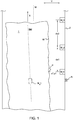
- Fig. 1 to 4 is a continuously transported in a transport direction x sheet metal strip designated by the reference numeral 1.
- the reference numeral 2 designates generally a frame of a device which may comprise transport belts, transport rollers, a roller leveling machine or the like for transporting the sheet metal strip 1 (not shown here).
- laser cutting device for cutting the metal strip 1 is arranged in sheet metal blanks with a predetermined geometry.
- the laser cutting device conventionally comprises one or more lasers, which are each movable in the transport direction x and a transverse direction y extending perpendicularly thereto.
- electric servomotors For moving each of the lasers in the x and y directions, electric servomotors may be provided, for example.
- a computer To control such servomotors usually a computer is provided in which a predetermined cutting path descriptive Schneidweg coordinates for moving each of the laser are stored.
- the cutting path coordinates describe a cutting path with respect to a center plane of the device, ie, for example, a center plane M of the frame 2 extending in the xy direction.
- a point P at one edge of the sheet metal strip 1 by means of a first y-measuring device M y 1 are detected.
- a distance of the point P in the y-direction with respect to a fixed to the frame 2 y-reference R is measured.
- a first x-coordinate x1 of the point P with respect to the reference R is determined with a first path measuring device M x 1.
- the first location coordinates x1y1 of the point P are stored.
- a second y-measuring device M y 2 is arranged at a first distance dx1.
- a movement of the sheet metal strip 1 in the transport direction x is determined with the second y-measuring means M y 2, a second y-coordinate y2 of the distance to the edge of the sheet metal bands. 1
- the first location coordinates x1y1 and the second location coordinates x2y2 each exactly describe the location of the same point P on the edge of the sheet metal strip 1.
- the edge of the metal strip 1 has an edge ripple W.
- a first y-correction value K y 1 can be determined.
- the y-coordinates of the cutting path coordinates can be corrected.
- a skew of the band center BM with respect to the center plane M can be determined and corrected.
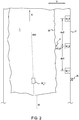
- the sheet metal strip 1 is a Has saberiness, ie a curvature with a large radius.
- a third y-measuring device M y 3 can be provided downstream of the second y-measuring device M y 2 at a second distance dx2.
- dx 1 dx 2
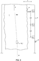
- the 4 to 6 schematically show a second variant of the method according to the invention.
- a second displacement measuring device M x 2 is arranged upstream of a designated with the reference numeral BF band flow measuring device.
- the band flow measuring device BF may be a device which is designed similarly to a mouse optical sensor.
- a camera for example an 18 ⁇ 18 CCD
- the point P may be, for example, an eruption on the surface of the metal strip 1, which appears dark in the image captured by the camera.
- the sheet-metal strip 1 has been moved in the transporting direction x by a distance dx3
- another image of the surface structure of the sheet-metal strip 1 is taken by means of the camera.
- the second location coordinates x2y2 of the point P are determined.
- the vector V describing the velocity and the direction of movement of the point P can then be determined.
- the third distance dx3 is for example 0.1 to 3.0 mm. Nevertheless, the vector defines a first coordinate pair x1y1 and a second coordinate pair x2y2.
- the coordinate pairs x1y1 and x2y2 and, in turn, the third y-correction value K y 3 can be determined from the vector V by means of conventional calculation methods.
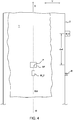
- a fourth y-measuring device M y 4 may be provided in the second aspect of the invention.
- the third y-correction value K y 3 can be corrected using a fourth y-coordinate y4 determined therewith.
- the fourth y-measuring device M y 4 can constantly the position, for example, the band edge of the metal strip 1, measured and used to determine a drift of the y-values. Using the measured drift, if the fourth distance dx4 is known, the third y correction value K y 3 determined by means of the band flow measuring device BF can be dynamically corrected.
Landscapes
- Engineering & Computer Science (AREA)
- Physics & Mathematics (AREA)
- General Physics & Mathematics (AREA)
- Optics & Photonics (AREA)
- Mechanical Engineering (AREA)
- Plasma & Fusion (AREA)
- Theoretical Computer Science (AREA)
- Computer Vision & Pattern Recognition (AREA)
- Human Computer Interaction (AREA)
- Automation & Control Theory (AREA)
- Manufacturing & Machinery (AREA)
- Quality & Reliability (AREA)
- Length Measuring Devices By Optical Means (AREA)
- Registering, Tensioning, Guiding Webs, And Rollers Therefor (AREA)
- Laser Beam Processing (AREA)
Applications Claiming Priority (2)
| Application Number | Priority Date | Filing Date | Title |
|---|---|---|---|
| DE102015203221.3A DE102015203221B3 (de) | 2015-02-23 | 2015-02-23 | Verfahren zur Korrektur eines vorgegebenen Schneidwegs zum Schneiden einer Blechplatine |
| PCT/EP2016/059202 WO2016135350A1 (de) | 2015-02-23 | 2016-04-25 | Verfahren zur korrektur eines vorgegebenen schneidwegs zum schneiden einer blechplatine |
Publications (2)
| Publication Number | Publication Date |
|---|---|
| EP3262471A1 EP3262471A1 (de) | 2018-01-03 |
| EP3262471B1 true EP3262471B1 (de) | 2019-05-22 |
Family
ID=55975032
Family Applications (1)
| Application Number | Title | Priority Date | Filing Date |
|---|---|---|---|
| EP16723033.3A Active EP3262471B1 (de) | 2015-02-23 | 2016-04-25 | Verfahren zur korrektur eines vorgegebenen schneidwegs zum schneiden einer blechplatine |
Country Status (8)
| Country | Link |
|---|---|
| US (1) | US10586320B2 (enExample) |
| EP (1) | EP3262471B1 (enExample) |
| JP (1) | JP6791866B2 (enExample) |
| CN (1) | CN107548476B (enExample) |
| DE (1) | DE102015203221B3 (enExample) |
| ES (1) | ES2742415T3 (enExample) |
| MX (1) | MX369029B (enExample) |
| WO (1) | WO2016135350A1 (enExample) |
Families Citing this family (13)
| Publication number | Priority date | Publication date | Assignee | Title |
|---|---|---|---|---|
| JP2018140419A (ja) * | 2017-02-28 | 2018-09-13 | 株式会社リコー | 光加工装置及び光加工物の生産方法 |
| EP3477248B1 (de) * | 2017-10-26 | 2023-06-07 | Heinrich Georg GmbH Maschinenfabrik | Inspektionssystem und verfahren zur fehleranalyse |
| JP6939581B2 (ja) * | 2018-01-10 | 2021-09-22 | Agc株式会社 | 曲面ガラス基板の加工方法及び製造方法 |
| CN109249138B (zh) * | 2018-11-12 | 2020-12-01 | 广州里程科技发展有限公司 | 激光雕刻机跨平台运动控制系统 |
| DE102019100661A1 (de) * | 2019-01-11 | 2020-07-16 | Dieffenbacher GmbH Maschinen- und Anlagenbau | Vermessungsvorrichtung und Verfahren zur Vermessung von Werkstoffplatten und Anlage |
| CN109865953B (zh) * | 2019-04-23 | 2024-01-19 | 安徽速达数控设备有限责任公司 | 一种待切割物料位置自动校正装置及其使用方法 |
| CN110834155A (zh) * | 2019-12-23 | 2020-02-25 | 雷科股份有限公司 | Aoi应用在激光蚀薄铜线圈的方法及其设备 |
| ES2971479T3 (es) * | 2020-02-13 | 2024-06-05 | Fagor Arrasate S Coop | Procedimiento e instalación para cortar un formato de chapa |
| CN113110289B (zh) * | 2021-04-25 | 2022-12-02 | 南通大学 | 一种环刀连续切割中回刀预判点优化方法 |
| CN113222941B (zh) * | 2021-05-17 | 2022-11-11 | 中冶赛迪信息技术(重庆)有限公司 | 连铸铸坯的切割状态确定方法、系统、设备及介质 |
| DE102021130870B3 (de) * | 2021-11-25 | 2022-12-15 | Sick Ag | Verfahren und vorrichtung zur vermessung von objekten |
| DE102023112933A1 (de) | 2023-05-16 | 2024-11-21 | Schuler Pressen Gmbh | Verfahren zum Schneiden von Platinen mit einer vorgegebenen Soll-Kontur |
| CN119115243B (zh) * | 2024-09-14 | 2025-04-25 | 武汉华工激光工程有限责任公司 | 晶圆切割过程中的切口校正和预警方法、晶圆切割设备 |
Family Cites Families (26)
| Publication number | Priority date | Publication date | Assignee | Title |
|---|---|---|---|---|
| US4047457A (en) * | 1975-11-11 | 1977-09-13 | Potomac Applied Mechanics, Inc. | Sheet metal cutting |
| JPS62212089A (ja) * | 1986-03-11 | 1987-09-18 | Amada Co Ltd | 板材加工機械における板材加工方法 |
| US5163008A (en) | 1990-08-21 | 1992-11-10 | Gerber Garment Technology, Inc. | Method and apparatus for advancing sheet material for the cutting of successive segments thereof |
| US5134911A (en) * | 1991-04-05 | 1992-08-04 | Gerber Garment Technology, Inc. | Method for the interrupted cutting of a line in sheet material |
| US5421185A (en) * | 1993-01-19 | 1995-06-06 | Spiro America, Inc. | Apparatus for cutting sheet material into curved segments |
| GB2297682B (en) * | 1995-02-08 | 1997-01-15 | Gerber Garment Technology Inc | Apparatus and method for bite cutting pattern pieces for made to order garments |
| US5727433A (en) * | 1995-09-08 | 1998-03-17 | Gerber Garment Technology, Inc. | Method for cutting sheet material |
| EP0841131A1 (de) * | 1996-11-07 | 1998-05-13 | Bullmer Spezialmaschinen GmbH | Schneidvorrichtung mit Hubregelung |
| GB2341132B (en) * | 1998-07-16 | 2000-08-23 | Gerber Technology Inc | Overlay pinch mechanism |
| GB2362596B (en) * | 2000-05-26 | 2002-07-10 | Gerber Technology Inc | An apparatus and method for cutting a layup of sheet material |
| DE10112445C2 (de) * | 2001-03-13 | 2003-03-20 | Fraunhofer Ges Forschung | Verfahren zum Schneiden von zu fügenden Bauteilen mit Laserstrahlung |
| DE50101445D1 (de) * | 2001-08-18 | 2004-03-11 | Trumpf Werkzeugmaschinen Gmbh | Werkzeugmaschine zum Bearbeiten von Werkstücken mittels eines Laserstrahls |
| JP4115930B2 (ja) * | 2003-12-26 | 2008-07-09 | 株式会社リコー | 位置調整方法と位置調整装置と組立装置及びそれにより組み立てられた印字ヘッド |
| DE102007042165B4 (de) | 2007-08-17 | 2009-09-10 | Schuler Automation Gmbh & Co. Kg | Vorrichtung und Verfahren zum kombinierten Plan- und Hochkantrichten eines Blechbands |
| CN102105256B (zh) * | 2008-02-20 | 2014-12-31 | 激光线圈技术有限公司 | 用于高速切削的渐进激光切料装置 |
| ES2360386T3 (es) * | 2008-03-12 | 2011-06-03 | SCHULER AUTOMATION GMBH & CO. KG | Dispositivo y procedimiento para la orientación de la posición de piezas de forma de placa. |
| US20120247297A1 (en) * | 2011-03-30 | 2012-10-04 | Brother Kogyo Kabushiki Kaisha | Cutting apparatus and cutting control program therefor |
| US9073162B2 (en) * | 2011-12-16 | 2015-07-07 | Peddinghaus Corporation | Method and apparatus for cutting a mill plate |
| JP2013193192A (ja) * | 2012-03-22 | 2013-09-30 | Brother Industries Ltd | 切断装置 |
| FR2993191B1 (fr) * | 2012-07-16 | 2015-01-16 | Snecma | Procedes et systeme de decoupe |
| US9415467B2 (en) * | 2013-01-08 | 2016-08-16 | Schuler Automation Gmbh & Co., Kg | Method of and device for producing a contour cut in a strip of sheet metal |
| DE102013203384B4 (de) * | 2013-02-28 | 2015-07-23 | Schuler Automation Gmbh & Co. Kg | Verfahren zum Schneiden einer Blechplatine |
| DE102013203385A1 (de) * | 2013-02-28 | 2014-08-28 | Schuler Automation Gmbh & Co. Kg | Verfahren zum Schneiden einer Blechplatine mit einer vorgegebenen Kontur |
| DE102013210878A1 (de) * | 2013-06-11 | 2014-12-11 | Schuler Automation Gmbh & Co. Kg | Verfahren und Vorrichtung zur Herstellung eines Blechformteils |
| EP2878920A1 (en) * | 2013-11-28 | 2015-06-03 | Hexagon Technology Center GmbH | Calibration of a coordinate measuring machine using a calibration laser head at the tool centre point |
| US8923656B1 (en) * | 2014-05-09 | 2014-12-30 | Silhouette America, Inc. | Correction of acquired images for cutting pattern creation |
-
2015
- 2015-02-23 DE DE102015203221.3A patent/DE102015203221B3/de not_active Expired - Fee Related
-
2016
- 2016-04-25 JP JP2017544578A patent/JP6791866B2/ja active Active
- 2016-04-25 CN CN201680011577.XA patent/CN107548476B/zh active Active
- 2016-04-25 EP EP16723033.3A patent/EP3262471B1/de active Active
- 2016-04-25 ES ES16723033T patent/ES2742415T3/es active Active
- 2016-04-25 US US15/552,734 patent/US10586320B2/en active Active
- 2016-04-25 WO PCT/EP2016/059202 patent/WO2016135350A1/de not_active Ceased
- 2016-04-25 MX MX2017010846A patent/MX369029B/es active IP Right Grant
Non-Patent Citations (1)
| Title |
|---|
| None * |
Also Published As
| Publication number | Publication date |
|---|---|
| MX2017010846A (es) | 2018-06-05 |
| ES2742415T3 (es) | 2020-02-14 |
| WO2016135350A8 (de) | 2017-04-27 |
| US20180047151A1 (en) | 2018-02-15 |
| JP2018512278A (ja) | 2018-05-17 |
| MX369029B (es) | 2019-10-25 |
| DE102015203221B3 (de) | 2016-06-09 |
| WO2016135350A1 (de) | 2016-09-01 |
| CN107548476B (zh) | 2021-08-17 |
| US10586320B2 (en) | 2020-03-10 |
| EP3262471A1 (de) | 2018-01-03 |
| JP6791866B2 (ja) | 2020-11-25 |
| CN107548476A (zh) | 2018-01-05 |
Similar Documents
| Publication | Publication Date | Title |
|---|---|---|
| EP3262471B1 (de) | Verfahren zur korrektur eines vorgegebenen schneidwegs zum schneiden einer blechplatine | |
| EP2828029B1 (de) | Verfahren zum schneiden einer blechplatine | |
| EP2961561B1 (de) | Verfahren zum schneiden einer blechplatine mit einer vorgegebenen kontur | |
| EP2950043B1 (de) | Verfahren zum ermitteln einer geschlossenen bahnkurve mittels eines lasers und einem laserlicht-sensor und vorrichtung zum ermitteln einer geschlossenen bahnkurve | |
| DE112014006253T5 (de) | Werkzeugformmessvorrichtung und Werkzeugformmessverfahren | |
| DE102010015884B4 (de) | Verfahren zur reproduzierbaren Bestimmung der Position von Strukturen auf einer Maske mit Pellicle-Rahmen | |
| EP2311583B1 (de) | Verfahren zur Bestimmung der Dicke eines Werkstückes mit einer Biegemaschine und eine solche Biegemaschine | |
| EP2583057A1 (de) | Vorrichtung und verfahren zur vermessung von oberflächen | |
| DE102014007201B4 (de) | Vorrichtung und Verfahren zur geometrischen Vermessung eines Objekts | |
| DE102009053874A1 (de) | Roboter zur automatischen 3D-Vermessung und Verfahren | |
| DE102013203383A1 (de) | Verfahren zum Schneiden einer Blechplatine | |
| EP1460375A2 (de) | Verfahren und Vorrichtung zum geometrischen Vermessen eines Materialbandes | |
| DE102018132461B3 (de) | Handgeführte Vorrichtung und Verfahren zur optischen berührungsfreien Bestimmung der Dicke eines gewalzten Metallbandes | |
| DE10393022T5 (de) | Verfahren und Vorrichtung zum Kalibrieren der Position von Klingen einer Rollenschneidmaschine von einer Papiermaschine oder Kartonmaschine | |
| DE102017003641A1 (de) | Verfahren zur Messung von Koordinaten oder Eigenschaften einer Werkstückoberfläche | |
| AT518377B1 (de) | Verfahren und Vorrichtung zur Behandlung von Flachglaseinheiten an einer glasverarbeitenden Anlage | |
| DE102007056773A1 (de) | Verfahren zum automatischen Bestimmen eines virtuellen Arbeitspunktes | |
| AT518560B1 (de) | Biegebalken für eine Schwenkbiegemaschine | |
| DE102020208567B4 (de) | Kalibrieren eines Referenzkörpers für die Führungsfehlerermittlung einer Maschinenachse | |
| EP3740734B1 (de) | Bestimmung der biegeverkürzung eines zu biegenden blechwerkstückes | |
| DE112009004710B4 (de) | Werkstückmessverfahren, Elektroerosions-Bearbeitungsverfahrenund Elektroerosions-Bearbeitungsvorrichtung | |
| DE102006048030A1 (de) | Vorrichtung und Verfahren zur Ermittlung von Spaltmaß und Bündigkeit angrenzender Bauteile | |
| DE102017221737B4 (de) | Verfahren und System zum Auswerten eines durch eine Messvorrichtung erfassten vorbestimmten Oberflächenbereichs eines Prüfkörpers | |
| DE102019121407A1 (de) | Verfahren zum quantitativen beurteilen einer qualität einer bearbeiteten oberfläche | |
| DE19945717A1 (de) | Verfahren und Anordnung zur berürhrungslosen Erfassung der Lage, der Geometrie und der Abmessungen großer Bauteile |
Legal Events
| Date | Code | Title | Description |
|---|---|---|---|
| STAA | Information on the status of an ep patent application or granted ep patent |
Free format text: STATUS: THE INTERNATIONAL PUBLICATION HAS BEEN MADE |
|
| PUAI | Public reference made under article 153(3) epc to a published international application that has entered the european phase |
Free format text: ORIGINAL CODE: 0009012 |
|
| STAA | Information on the status of an ep patent application or granted ep patent |
Free format text: STATUS: REQUEST FOR EXAMINATION WAS MADE |
|
| 17P | Request for examination filed |
Effective date: 20170825 |
|
| AK | Designated contracting states |
Kind code of ref document: A1 Designated state(s): AL AT BE BG CH CY CZ DE DK EE ES FI FR GB GR HR HU IE IS IT LI LT LU LV MC MK MT NL NO PL PT RO RS SE SI SK SM TR |
|
| AX | Request for extension of the european patent |
Extension state: BA ME |
|
| DAV | Request for validation of the european patent (deleted) | ||
| DAX | Request for extension of the european patent (deleted) | ||
| RIC1 | Information provided on ipc code assigned before grant |
Ipc: G05B 19/402 20060101AFI20181017BHEP Ipc: G06T 7/70 20170101ALI20181017BHEP Ipc: B23K 26/08 20140101ALI20181017BHEP Ipc: B23K 26/38 20140101ALI20181017BHEP Ipc: G01B 11/04 20060101ALI20181017BHEP |
|
| GRAP | Despatch of communication of intention to grant a patent |
Free format text: ORIGINAL CODE: EPIDOSNIGR1 |
|
| STAA | Information on the status of an ep patent application or granted ep patent |
Free format text: STATUS: GRANT OF PATENT IS INTENDED |
|
| INTG | Intention to grant announced |
Effective date: 20181218 |
|
| GRAS | Grant fee paid |
Free format text: ORIGINAL CODE: EPIDOSNIGR3 |
|
| GRAA | (expected) grant |
Free format text: ORIGINAL CODE: 0009210 |
|
| STAA | Information on the status of an ep patent application or granted ep patent |
Free format text: STATUS: THE PATENT HAS BEEN GRANTED |
|
| RAP1 | Party data changed (applicant data changed or rights of an application transferred) |
Owner name: SCHULER PRESSEN GMBH |
|
| AK | Designated contracting states |
Kind code of ref document: B1 Designated state(s): AL AT BE BG CH CY CZ DE DK EE ES FI FR GB GR HR HU IE IS IT LI LT LU LV MC MK MT NL NO PL PT RO RS SE SI SK SM TR |
|
| REG | Reference to a national code |
Ref country code: GB Ref legal event code: FG4D Free format text: NOT ENGLISH |
|
| REG | Reference to a national code |
Ref country code: CH Ref legal event code: EP |
|
| REG | Reference to a national code |
Ref country code: IE Ref legal event code: FG4D Free format text: LANGUAGE OF EP DOCUMENT: GERMAN |
|
| REG | Reference to a national code |
Ref country code: DE Ref legal event code: R096 Ref document number: 502016004793 Country of ref document: DE |
|
| REG | Reference to a national code |
Ref country code: AT Ref legal event code: REF Ref document number: 1136875 Country of ref document: AT Kind code of ref document: T Effective date: 20190615 |
|
| REG | Reference to a national code |
Ref country code: NL Ref legal event code: FP |
|
| REG | Reference to a national code |
Ref country code: LT Ref legal event code: MG4D |
|
| PG25 | Lapsed in a contracting state [announced via postgrant information from national office to epo] |
Ref country code: FI Free format text: LAPSE BECAUSE OF FAILURE TO SUBMIT A TRANSLATION OF THE DESCRIPTION OR TO PAY THE FEE WITHIN THE PRESCRIBED TIME-LIMIT Effective date: 20190522 Ref country code: LT Free format text: LAPSE BECAUSE OF FAILURE TO SUBMIT A TRANSLATION OF THE DESCRIPTION OR TO PAY THE FEE WITHIN THE PRESCRIBED TIME-LIMIT Effective date: 20190522 Ref country code: SE Free format text: LAPSE BECAUSE OF FAILURE TO SUBMIT A TRANSLATION OF THE DESCRIPTION OR TO PAY THE FEE WITHIN THE PRESCRIBED TIME-LIMIT Effective date: 20190522 Ref country code: NO Free format text: LAPSE BECAUSE OF FAILURE TO SUBMIT A TRANSLATION OF THE DESCRIPTION OR TO PAY THE FEE WITHIN THE PRESCRIBED TIME-LIMIT Effective date: 20190822 Ref country code: PT Free format text: LAPSE BECAUSE OF FAILURE TO SUBMIT A TRANSLATION OF THE DESCRIPTION OR TO PAY THE FEE WITHIN THE PRESCRIBED TIME-LIMIT Effective date: 20190922 Ref country code: HR Free format text: LAPSE BECAUSE OF FAILURE TO SUBMIT A TRANSLATION OF THE DESCRIPTION OR TO PAY THE FEE WITHIN THE PRESCRIBED TIME-LIMIT Effective date: 20190522 Ref country code: AL Free format text: LAPSE BECAUSE OF FAILURE TO SUBMIT A TRANSLATION OF THE DESCRIPTION OR TO PAY THE FEE WITHIN THE PRESCRIBED TIME-LIMIT Effective date: 20190522 |
|
| PG25 | Lapsed in a contracting state [announced via postgrant information from national office to epo] |
Ref country code: GR Free format text: LAPSE BECAUSE OF FAILURE TO SUBMIT A TRANSLATION OF THE DESCRIPTION OR TO PAY THE FEE WITHIN THE PRESCRIBED TIME-LIMIT Effective date: 20190823 Ref country code: RS Free format text: LAPSE BECAUSE OF FAILURE TO SUBMIT A TRANSLATION OF THE DESCRIPTION OR TO PAY THE FEE WITHIN THE PRESCRIBED TIME-LIMIT Effective date: 20190522 Ref country code: BG Free format text: LAPSE BECAUSE OF FAILURE TO SUBMIT A TRANSLATION OF THE DESCRIPTION OR TO PAY THE FEE WITHIN THE PRESCRIBED TIME-LIMIT Effective date: 20190822 Ref country code: LV Free format text: LAPSE BECAUSE OF FAILURE TO SUBMIT A TRANSLATION OF THE DESCRIPTION OR TO PAY THE FEE WITHIN THE PRESCRIBED TIME-LIMIT Effective date: 20190522 |
|
| PG25 | Lapsed in a contracting state [announced via postgrant information from national office to epo] |
Ref country code: EE Free format text: LAPSE BECAUSE OF FAILURE TO SUBMIT A TRANSLATION OF THE DESCRIPTION OR TO PAY THE FEE WITHIN THE PRESCRIBED TIME-LIMIT Effective date: 20190522 Ref country code: DK Free format text: LAPSE BECAUSE OF FAILURE TO SUBMIT A TRANSLATION OF THE DESCRIPTION OR TO PAY THE FEE WITHIN THE PRESCRIBED TIME-LIMIT Effective date: 20190522 Ref country code: SK Free format text: LAPSE BECAUSE OF FAILURE TO SUBMIT A TRANSLATION OF THE DESCRIPTION OR TO PAY THE FEE WITHIN THE PRESCRIBED TIME-LIMIT Effective date: 20190522 Ref country code: RO Free format text: LAPSE BECAUSE OF FAILURE TO SUBMIT A TRANSLATION OF THE DESCRIPTION OR TO PAY THE FEE WITHIN THE PRESCRIBED TIME-LIMIT Effective date: 20190522 Ref country code: CZ Free format text: LAPSE BECAUSE OF FAILURE TO SUBMIT A TRANSLATION OF THE DESCRIPTION OR TO PAY THE FEE WITHIN THE PRESCRIBED TIME-LIMIT Effective date: 20190522 |
|
| REG | Reference to a national code |
Ref country code: ES Ref legal event code: FG2A Ref document number: 2742415 Country of ref document: ES Kind code of ref document: T3 Effective date: 20200214 |
|
| REG | Reference to a national code |
Ref country code: DE Ref legal event code: R097 Ref document number: 502016004793 Country of ref document: DE |
|
| PG25 | Lapsed in a contracting state [announced via postgrant information from national office to epo] |
Ref country code: SM Free format text: LAPSE BECAUSE OF FAILURE TO SUBMIT A TRANSLATION OF THE DESCRIPTION OR TO PAY THE FEE WITHIN THE PRESCRIBED TIME-LIMIT Effective date: 20190522 |
|
| PLBE | No opposition filed within time limit |
Free format text: ORIGINAL CODE: 0009261 |
|
| STAA | Information on the status of an ep patent application or granted ep patent |
Free format text: STATUS: NO OPPOSITION FILED WITHIN TIME LIMIT |
|
| PG25 | Lapsed in a contracting state [announced via postgrant information from national office to epo] |
Ref country code: TR Free format text: LAPSE BECAUSE OF FAILURE TO SUBMIT A TRANSLATION OF THE DESCRIPTION OR TO PAY THE FEE WITHIN THE PRESCRIBED TIME-LIMIT Effective date: 20190522 |
|
| 26N | No opposition filed |
Effective date: 20200225 |
|
| PG25 | Lapsed in a contracting state [announced via postgrant information from national office to epo] |
Ref country code: PL Free format text: LAPSE BECAUSE OF FAILURE TO SUBMIT A TRANSLATION OF THE DESCRIPTION OR TO PAY THE FEE WITHIN THE PRESCRIBED TIME-LIMIT Effective date: 20190522 |
|
| PG25 | Lapsed in a contracting state [announced via postgrant information from national office to epo] |
Ref country code: SI Free format text: LAPSE BECAUSE OF FAILURE TO SUBMIT A TRANSLATION OF THE DESCRIPTION OR TO PAY THE FEE WITHIN THE PRESCRIBED TIME-LIMIT Effective date: 20190522 |
|
| PGFP | Annual fee paid to national office [announced via postgrant information from national office to epo] |
Ref country code: NL Payment date: 20200420 Year of fee payment: 5 |
|
| PGFP | Annual fee paid to national office [announced via postgrant information from national office to epo] |
Ref country code: GB Payment date: 20200423 Year of fee payment: 5 |
|
| PG25 | Lapsed in a contracting state [announced via postgrant information from national office to epo] |
Ref country code: MC Free format text: LAPSE BECAUSE OF FAILURE TO SUBMIT A TRANSLATION OF THE DESCRIPTION OR TO PAY THE FEE WITHIN THE PRESCRIBED TIME-LIMIT Effective date: 20190522 |
|
| REG | Reference to a national code |
Ref country code: CH Ref legal event code: PL |
|
| PG25 | Lapsed in a contracting state [announced via postgrant information from national office to epo] |
Ref country code: LI Free format text: LAPSE BECAUSE OF NON-PAYMENT OF DUE FEES Effective date: 20200430 Ref country code: CH Free format text: LAPSE BECAUSE OF NON-PAYMENT OF DUE FEES Effective date: 20200430 |
|
| PG25 | Lapsed in a contracting state [announced via postgrant information from national office to epo] |
Ref country code: IE Free format text: LAPSE BECAUSE OF NON-PAYMENT OF DUE FEES Effective date: 20200425 |
|
| REG | Reference to a national code |
Ref country code: NL Ref legal event code: MM Effective date: 20210501 |
|
| GBPC | Gb: european patent ceased through non-payment of renewal fee |
Effective date: 20210425 |
|
| PG25 | Lapsed in a contracting state [announced via postgrant information from national office to epo] |
Ref country code: GB Free format text: LAPSE BECAUSE OF NON-PAYMENT OF DUE FEES Effective date: 20210425 |
|
| PG25 | Lapsed in a contracting state [announced via postgrant information from national office to epo] |
Ref country code: NL Free format text: LAPSE BECAUSE OF NON-PAYMENT OF DUE FEES Effective date: 20210501 |
|
| PG25 | Lapsed in a contracting state [announced via postgrant information from national office to epo] |
Ref country code: MT Free format text: LAPSE BECAUSE OF FAILURE TO SUBMIT A TRANSLATION OF THE DESCRIPTION OR TO PAY THE FEE WITHIN THE PRESCRIBED TIME-LIMIT Effective date: 20190522 Ref country code: CY Free format text: LAPSE BECAUSE OF FAILURE TO SUBMIT A TRANSLATION OF THE DESCRIPTION OR TO PAY THE FEE WITHIN THE PRESCRIBED TIME-LIMIT Effective date: 20190522 |
|
| REG | Reference to a national code |
Ref country code: AT Ref legal event code: MM01 Ref document number: 1136875 Country of ref document: AT Kind code of ref document: T Effective date: 20210425 |
|
| PG25 | Lapsed in a contracting state [announced via postgrant information from national office to epo] |
Ref country code: MK Free format text: LAPSE BECAUSE OF FAILURE TO SUBMIT A TRANSLATION OF THE DESCRIPTION OR TO PAY THE FEE WITHIN THE PRESCRIBED TIME-LIMIT Effective date: 20190522 Ref country code: IS Free format text: LAPSE BECAUSE OF FAILURE TO SUBMIT A TRANSLATION OF THE DESCRIPTION OR TO PAY THE FEE WITHIN THE PRESCRIBED TIME-LIMIT Effective date: 20190922 |
|
| PG25 | Lapsed in a contracting state [announced via postgrant information from national office to epo] |
Ref country code: AT Free format text: LAPSE BECAUSE OF NON-PAYMENT OF DUE FEES Effective date: 20210425 |
|
| P01 | Opt-out of the competence of the unified patent court (upc) registered |
Effective date: 20230528 |
|
| PGFP | Annual fee paid to national office [announced via postgrant information from national office to epo] |
Ref country code: LU Payment date: 20240418 Year of fee payment: 9 |
|
| PGFP | Annual fee paid to national office [announced via postgrant information from national office to epo] |
Ref country code: BE Payment date: 20240419 Year of fee payment: 9 |
|
| PGFP | Annual fee paid to national office [announced via postgrant information from national office to epo] |
Ref country code: DE Payment date: 20250317 Year of fee payment: 10 |
|
| PGFP | Annual fee paid to national office [announced via postgrant information from national office to epo] |
Ref country code: ES Payment date: 20250519 Year of fee payment: 10 |
|
| PGFP | Annual fee paid to national office [announced via postgrant information from national office to epo] |
Ref country code: IT Payment date: 20250430 Year of fee payment: 10 |
|
| PGFP | Annual fee paid to national office [announced via postgrant information from national office to epo] |
Ref country code: FR Payment date: 20250422 Year of fee payment: 10 |