EP3261783B1 - Anlage und verfahren für das behandeln eines werkstücks - Google Patents
Anlage und verfahren für das behandeln eines werkstücks Download PDFInfo
- Publication number
- EP3261783B1 EP3261783B1 EP16700103.1A EP16700103A EP3261783B1 EP 3261783 B1 EP3261783 B1 EP 3261783B1 EP 16700103 A EP16700103 A EP 16700103A EP 3261783 B1 EP3261783 B1 EP 3261783B1
- Authority
- EP
- European Patent Office
- Prior art keywords
- workpiece
- process chamber
- fluid
- cavity
- process fluid
- Prior art date
- Legal status (The legal status is an assumption and is not a legal conclusion. Google has not performed a legal analysis and makes no representation as to the accuracy of the status listed.)
- Active
Links
Images




Classifications
-
- B—PERFORMING OPERATIONS; TRANSPORTING
- B08—CLEANING
- B08B—CLEANING IN GENERAL; PREVENTION OF FOULING IN GENERAL
- B08B3/00—Cleaning by methods involving the use or presence of liquid or steam
- B08B3/04—Cleaning involving contact with liquid
- B08B3/10—Cleaning involving contact with liquid with additional treatment of the liquid or of the object being cleaned, e.g. by heat, by electricity or by vibration
-
- B—PERFORMING OPERATIONS; TRANSPORTING
- B08—CLEANING
- B08B—CLEANING IN GENERAL; PREVENTION OF FOULING IN GENERAL
- B08B9/00—Cleaning hollow articles by methods or apparatus specially adapted thereto
-
- B—PERFORMING OPERATIONS; TRANSPORTING
- B08—CLEANING
- B08B—CLEANING IN GENERAL; PREVENTION OF FOULING IN GENERAL
- B08B7/00—Cleaning by methods not provided for in a single other subclass or a single group in this subclass
- B08B7/02—Cleaning by methods not provided for in a single other subclass or a single group in this subclass by distortion, beating, or vibration of the surface to be cleaned
- B08B7/026—Using sound waves
- B08B7/028—Using ultrasounds
-
- B—PERFORMING OPERATIONS; TRANSPORTING
- B08—CLEANING
- B08B—CLEANING IN GENERAL; PREVENTION OF FOULING IN GENERAL
- B08B2209/00—Details of machines or methods for cleaning hollow articles
- B08B2209/005—Use of ultrasonics or cavitation, e.g. as primary or secondary action
-
- B—PERFORMING OPERATIONS; TRANSPORTING
- B08—CLEANING
- B08B—CLEANING IN GENERAL; PREVENTION OF FOULING IN GENERAL
- B08B3/00—Cleaning by methods involving the use or presence of liquid or steam
- B08B3/04—Cleaning involving contact with liquid
- B08B3/10—Cleaning involving contact with liquid with additional treatment of the liquid or of the object being cleaned, e.g. by heat, by electricity or by vibration
- B08B3/12—Cleaning involving contact with liquid with additional treatment of the liquid or of the object being cleaned, e.g. by heat, by electricity or by vibration by sonic or ultrasonic vibrations
-
- B—PERFORMING OPERATIONS; TRANSPORTING
- B08—CLEANING
- B08B—CLEANING IN GENERAL; PREVENTION OF FOULING IN GENERAL
- B08B9/00—Cleaning hollow articles by methods or apparatus specially adapted thereto
- B08B9/02—Cleaning pipes or tubes or systems of pipes or tubes
- B08B9/027—Cleaning the internal surfaces; Removal of blockages
- B08B9/032—Cleaning the internal surfaces; Removal of blockages by the mechanical action of a moving fluid, e.g. by flushing
- B08B9/035—Cleaning the internal surfaces; Removal of blockages by the mechanical action of a moving fluid, e.g. by flushing by suction
-
- F—MECHANICAL ENGINEERING; LIGHTING; HEATING; WEAPONS; BLASTING
- F02—COMBUSTION ENGINES; HOT-GAS OR COMBUSTION-PRODUCT ENGINE PLANTS
- F02F—CYLINDERS, PISTONS OR CASINGS, FOR COMBUSTION ENGINES; ARRANGEMENTS OF SEALINGS IN COMBUSTION ENGINES
- F02F2200/00—Manufacturing
- F02F2200/06—Casting
-
- F—MECHANICAL ENGINEERING; LIGHTING; HEATING; WEAPONS; BLASTING
- F02—COMBUSTION ENGINES; HOT-GAS OR COMBUSTION-PRODUCT ENGINE PLANTS
- F02F—CYLINDERS, PISTONS OR CASINGS, FOR COMBUSTION ENGINES; ARRANGEMENTS OF SEALINGS IN COMBUSTION ENGINES
- F02F7/00—Casings, e.g. crankcases
- F02F7/0095—Constructing engine casings
Definitions
- the invention relates to a plant for treating a workpiece with a process fluid having a workpiece body having at least one cavity extending from a first opening to a second opening.
- the system includes a conduit system for supplying the process fluid having at least one conduit with an adapter for connecting the conduit system to the at least one cavity.
- the invention also relates to a method of treating a workpiece with a process fluid having a workpiece body having at least one cavity extending from a first opening to a second opening.
- the system includes a suction device connected to the process chamber for generating a negative pressure through a suction channel for drawing the process fluid from a fluid container through the at least one conduit and the at least one cavity into the process chamber.
- the invention also relates to a method of treating a workpiece with a process fluid having a workpiece body having at least one cavity extending from a first opening to a second opening.
- Dirt particles, in particular Spangut, dust, cast sand or liquid droplets can the function of industrially manufactured products such. B. affect injectors for internal combustion engines. The cleanliness of workpieces in industrial production processes is therefore of great importance. In industrial manufacturing, therefore, systems for the treatment of workpieces are used, in which the workpieces are cleaned and deburred. In such cleaning systems, the workpieces are subjected to a process fluid, for. B. with water, which is preferably provided with cleaning additives, or with liquid containing hydrocarbons.
- the DE 44 41 401 A1 discloses a device for cleaning medical instruments, which are immersed in an open tub in a disinfecting liquid for this purpose.
- the instruments are connected by means of an adapter to a suction nozzle connected to a suction nozzle. With the suction pump, the disinfecting liquid is circulated through an instrument in the tub.
- DE 10 2005 019 285 B3 describes a plant a method for cleaning cast workpieces used in engine construction, where there are branched interiors and channels.
- a workpiece to be cleaned is connected here by means of adapters to a pipe or hose line, which serves for supplying cleaning liquid into the interior of the workpiece.
- the object of the invention is to provide a plant for the treatment of workpieces with a process fluid which has a workpiece body with at least one of a first opening to a second opening Have cavity in which not only the walls of cavities of the workpiece, but also other surfaces of the workpiece are acted upon by the process fluid.
- a process chamber for receiving the workpiece during the treatment which has an outlet for discharging introduced into the cavity for the treatment of the workpiece process fluid.
- a system according to the invention can be designed, in particular, as a system for the cleaning of workpieces which have a workpiece body with at least one cavity which extends from a first opening to a second opening. In such a plant it is possible to clean both surfaces of the at least one cavity in the workpieces as well as surfaces lying on the outside of the workpieces.
- a process fluid in a system according to the invention can, for. As water, washing liquor or solvent-based cleaner can be used.
- the process fluid can also be designed as a foam, as an acid, as a cooling lubricant or as an oil.
- plant according to the invention can also be solids, such as ice pellets, salts, microbubbles, granules are used, but also gases, eg. For example, air.
- a suction device which is connected to the process chamber for generating a negative pressure through a suction channel to suck the process fluid from a fluid container through the at least one duct and the at least one cavity in the process chamber.
- This suction device may include a vacuum container communicating with the suction channel and an evacuating device for evacuating the vacuum container.
- connection channel communicating with the at least one line channel and connected to the fluid container for supplying the process fluid into the at least one line channel and for discharging process fluid from the process chamber to the vacuum container connected.
- the connection channel has a first valve for selectively releasing and blocking the supply of process fluid into the process chamber from the fluid container and includes a second valve for selectively connecting and disconnecting the vacuum container and the process chamber.
- the system contains a further conduit communicating with the outlet of the process chamber and the vacuum container with a shut-off valve for selectively enabling and inhibiting fluid flow between the process chamber and the vacuum container through the further conduit.
- the at least one cavity of a workpiece arranged in the process chamber can be flowed through in opposite directions by the process fluid.
- a cleaning action of process fluid is significantly improved. Contaminations that can jam or deposit on bottlenecks or undercuts are loosened or flushed when the flow is reversed.
- the suction channel in the system communicates with the outlet of the process chamber and the vacuum container, wherein in the suction channel, a shut-off valve for selectively enabling and suppressing a fluid flow through the suction channel between the process chamber and the vacuum container is arranged.
- the vacuum container preferably has a closable with a shut-off valve outlet.
- the system may also include means for applying at least one cavity in the workpiece to the process chamber having at least one jet consisting of a medium selected from the group consisting of: process fluid, especially liquid medium, vapor, gaseous medium, ice pellets, abrasives , Alternatively or additionally, a device for pressurizing the process chamber with a gaseous fluid, in particular compressed air, may also be provided in the system. In order to achieve an improved cleaning effect, it is advantageous if the system has a device for applying ultrasound to the at least one workpiece in the process chamber.
- the inventive method for treating a workpiece with a process fluid having a workpiece body having at least one cavity extending from a first opening to a second opening the workpiece to be treated in a first step in a process chamber arranged.
- the process fluid is then sucked through at least one cavity in the workpiece into the process chamber, wherein the surface of the workpiece in the cavity and external surfaces of the workpiece are subjected to the process fluid.
- the wall surfaces of the at least one cavity can be flown by the process fluid in different flow directions.
- the workpiece is arranged in the process chamber such that the second opening of the workpiece body is located on an outlet of the process chamber facing side of the workpiece, wherein the process fluid in the process chamber through the first opening and the cavity to the second Opening of the workpiece body flows.
- the at least one cavity in the workpiece body can also be supplied with gaseous fluid that is under pressure, in particular with compressed air after releasing the process fluid from the process chamber.
- fluid medium is injected into the at least one cavity in the process chamber.
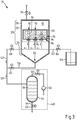
- the plant 10 in Fig. 1 for treating workpieces 14 with a process fluid 18 is designed as a facility for cleaning the workpieces 14.
- the process fluid 18 in the system 10 is a liquid, e.g. B. water.
- a process chamber 12 for receiving a workpiece 14 to be treated In the plant 10 there is a process chamber 12 for receiving a workpiece 14 to be treated.
- the process chamber 12 is formed in a vessel-shaped container 20 having a cylindrical side wall 22 and a funnel-shaped bottom 24 with an outlet 26.
- the vessel-shaped container 20 can be closed with a cover 28.
- the line system in the system 10 has a connection channel 42, which connects a fluid container 44 with ducts 46, which are connected to the adapter 34.
- the system 10 includes a suction device 48, which is connected by a suction channel 50 to an outlet 52 of the process chamber 12.
- the suction device 48 serves to generate a negative pressure in the process chamber 12.
- the suction device 48 has a vacuum container 54 and has an evacuation device 58 connected to the vacuum container 54 through a suction line 56 with a vacuum pump.
- a shut-off valve 60 is arranged, by means of which the suction line 56 can be selectively locked and released to connect the evacuation device 58 to the vacuum tank 54 or to separate the evacuating device 58 from the vacuum container 54.
- the vacuum vessel 54 has an outlet 64 closable with a shut-off valve 62 for the removal of process fluid 18.
- the connecting channel 42 opens into the suction channel 50.
- a first adjustable valve 66 and another adjustable valve 68 is arranged, which can be controlled with a computer unit (not shown).
- the second adjustable valve 68 is for selectively enabling and disabling the flow of process fluid 18 from the conduit 46 to the vacuum vessel 54 of the aspirator 48.
- a check valve 65 for disengaging and disabling the aspiration conduit 50, there is a check valve 65 in the system 10.
- the vessel-shaped vessel 20 can be vented via a vent valve 94.
- a first step In order to treat a workpiece 14 with the process fluid 18 in the process chamber 12 of the system 10 and to clean it, in a first step, the workpiece 14 in the workpiece receiving area 30 on the side of the first openings 36 in the process chamber 12 to the adapter 34 created.
- the adjustable valve 68 in the connection channel 42 and the shut-off valve 65 in the suction channel 50 are closed.
- a vacuum of about 950 mbar is then generated in the vacuum vessel 54 in a third step by means of the evacuation device 58, the shut-off valve 62 being closed.
- shut-off valve 65 and the valve 66 are then opened.
- This measure has the effect that the process chamber 12 is abruptly subjected to the negative pressure in the vacuum container 54 of the suction device 48. Due to this negative pressure is from the fluid container 44th through the ducts 46 and the adapter 34 then sucked through the openings 36 of the workpiece body 32 process fluid 18 in the cavity 38 formed therein. The process fluid 18 sucked into the cavity 38 then passes through the not covered by the adapter 34 openings 70 in the interior of the process chamber 12th
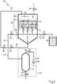
- the Fig. 2 shows the plant 10 in one of the in the Fig. 1 shown operating state with sucked into the process chamber 12 through the openings 36 and the cavity 38 of the workpiece 14 process fluid 18 from the fluid container 44.
- the valve 68 of the system 10 is closed in a fourth step.
- the process fluid 18 then flows in the direction indicated by the arrows 74 flow direction through the cavity 38 into the process chamber 12 a.
- On the walls of the cavity 38 accumulated dirt particles and contaminants 39 are removed here by the process fluid 18 and rinsed into the process chamber 12.
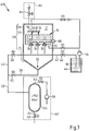
- the Fig. 3 shows the plant 10 in one of the in the Fig. 1 and the Fig. 2 shown operating states various other operating condition.
- the shut-off valve 65 in the suction channel 50 is hereby blocked again in a fifth step, the valve 66 in the connecting channel 42 is closed and the valve 68 in the connecting channel 42 is opened.
- the process fluid 18 is then sucked in the direction indicated by the arrows 76 flow direction by means of the suction device 48 through the cavity 38 in the workpiece body 32 of the workpiece 14 and registered in the vacuum container 54 of the suction device 48.
- the flow direction of the process fluid 18 is the direction indicated by the arrows 76 flow direction in the in the Fig. 2 shown operating state of the system 10 opposite. In this case, dirt particles and contaminants deposited on the walls of the cavity 38 are again removed from the process fluid 18 and thus reach the vacuum container 54.
- the process fluid 18 collected in the vacuum vessel 54 is then removed from the vacuum vessel 54 of the suction device 48 by opening the shut-off valve 62 in the outlet 64.
- the shut-off valve 60 is closed.
- the abovementioned steps can optionally be repeated several times in succession.
- the cover 28 of the process chamber When the cover 28 of the process chamber is open, the workpiece 14 is then removed from the process chamber 12 in order then to treat a further, corresponding workpiece in the process chamber 12.
- the Fig. 4 shows a second system 110 for the treatment of a workpiece 14.
- assemblies and elements in the Fig. 1 to Fig. 3 shown assemblies and elements correspond functionally, these are there identified by respective numbers as reference numerals.
- the suction channel 50 opens for the application of negative pressure in the process chamber 12 in the portion of the lid 28.
- the system 110 includes a conduit 78 with a check valve 80, are moved by the process fluid 18 from the process chamber 12 into the vacuum vessel 54 can.
- the check valve 65 is opened when the vacuum tank 54 of the evacuation device 58 is evacuated.
- the adjustable valves 66, 68 are closed.
- the shut-off valve 80 in the conduit 78 is locked.
- valve 66 By opening the valve 66, the inflow of process fluid 18 into the process chamber 12 through the cavity 38 of the workpiece 14 from the fluid container 44 is effected.
- the check valve 65 and the valve 66 are locked.
- the valve 68 is opened so that process fluid 18 passes through the connecting channel 42 and the suction channel 50 into the vacuum container 54 of the suction device 48 with one of the flow direction when flowing into the process chamber 12 opposite flow direction.
- valves 68 and the shut-off valve 80 can be opened and closed with a time delay to each other.
- the valve 68 may be opened in front of the shut-off valve 80 to cause the process fluid 18 to be initially drawn through the cavity 38 in the workpiece body 32 of the workpiece 14. Then, the valve 68 is closed to then suck the contaminant-laden process fluid via the outlet 26 of the container 20 by means of the suction device 48.
- the Fig. 5 shows a third plant 210 for the treatment of a workpiece 14th
- a device 82 for providing compressed air for pressurizing the process chamber 12 with compressed air through a valve 84 serves to expel process fluid 18 accumulated in the process chamber 12 by means of compressed air, e.g. B. when the valves 65, 66, 68 are closed and the valve 80 is opened or when the valves 65, 66 and the shut-off valve 80 are closed and the valve 68 is opened.
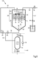
- the Fig. 6 shows a fourth plant 310 for the treatment of a workpiece 14.
- assemblies and elements in the Fig. 1 to Fig. 5 shown assemblies and elements correspond these are identified there by the same numbers as reference numerals.
- the system 310 includes means 83 for applying the at least one cavity 38 in the workpiece 14 to at least one jet 85 of process fluid 18 from a nozzle 86.
- the jet 85 is also from one of the process fluid 18 different other liquid, fluid, in particular gaseous medium may exist.
- the jet 85 may, for. B. be a steam jet.
- the nozzle jet 85 can basically also consist of ice pellets or other abrasives.
- the Fig. 7 shows a fifth plant 410 for the treatment of a workpiece 14.
- the system 410 contains a device 88 for applying ultrasound to the at least one workpiece 14 in the process chamber 12.
- a device 88 for applying ultrasound to the at least one workpiece 14 in the process chamber 12.
- spray nozzles 90 and flood nozzles 92 for applying the process fluid 18 from the fluid container 44 through a conduit 96 to a feed pump 98.
- the Fig. 8 shows a sixth plant 510 for the treatment of a workpiece 14.
- the workpiece 14 is arranged in the container 20 here such that the openings 36 face the funnel-shaped bottom 24 of the container.
- adapter 34 here through the ducts 46 from the fluid container 44 into the cavity 38 of the workpiece 14 flowing fluid 18 through the openings 36 of the cavity 38 to reach the outlet 26 of the container 20, without the fluid thereby flows over the outer surfaces of the Maschinenstücc stresses 32. This ensures that when treating a workpiece 14 in the workpiece receiving area 30 of the process chamber dirt particles from the interior of the cavity 38 do not reach the outer surfaces of the workpiece body 32 and soil these surfaces.
- the system 510 includes a vent valve 94 that communicates with the conduit 46 and allows venting of the process chamber 12 through the interior of the cavity 38 in the workpiece 14.
- a vent valve 94 that communicates with the conduit 46 and allows venting of the process chamber 12 through the interior of the cavity 38 in the workpiece 14.
- process fluid 18 in the systems described above can be used.
- Process fluid can also be a solid.
- process fluid are in principle also other gases, eg. For example, air.
- the system 10, 110, 210, 310, 410, 510 contains a line system for supplying the process fluid 18, which has at least one line channel 46 with an adapter 34 adapted to the workpiece body 32 for connecting the line system to the at least one cavity 38.
- a process chamber 12 for receiving the workpiece 14 during treatment, which has an outlet 26 for discharging process fluid 18 introduced into the cavity 38 for treating the workpiece 14.
Landscapes
- Engineering & Computer Science (AREA)
- Mechanical Engineering (AREA)
- Cleaning By Liquid Or Steam (AREA)
- Cleaning In General (AREA)
Priority Applications (1)
| Application Number | Priority Date | Filing Date | Title |
|---|---|---|---|
| PL16700103T PL3261783T3 (pl) | 2015-02-24 | 2016-01-05 | Urządzenie i sposób do czyszczenia elementu obrabianego |
Applications Claiming Priority (2)
| Application Number | Priority Date | Filing Date | Title |
|---|---|---|---|
| DE102015203323.6A DE102015203323A1 (de) | 2015-02-24 | 2015-02-24 | Anlage und Verfahren für das Behandeln eines Werkstücks |
| PCT/EP2016/050086 WO2016134860A1 (de) | 2015-02-24 | 2016-01-05 | Anlage und verfahren für das behandeln eines werkstücks |
Publications (2)
| Publication Number | Publication Date |
|---|---|
| EP3261783A1 EP3261783A1 (de) | 2018-01-03 |
| EP3261783B1 true EP3261783B1 (de) | 2019-08-21 |
Family
ID=55072655
Family Applications (1)
| Application Number | Title | Priority Date | Filing Date |
|---|---|---|---|
| EP16700103.1A Active EP3261783B1 (de) | 2015-02-24 | 2016-01-05 | Anlage und verfahren für das behandeln eines werkstücks |
Country Status (6)
| Country | Link |
|---|---|
| US (1) | US20170348740A1 (pl) |
| EP (1) | EP3261783B1 (pl) |
| CN (1) | CN107249764A (pl) |
| DE (1) | DE102015203323A1 (pl) |
| PL (1) | PL3261783T3 (pl) |
| WO (1) | WO2016134860A1 (pl) |
Families Citing this family (5)
| Publication number | Priority date | Publication date | Assignee | Title |
|---|---|---|---|---|
| DE102016009094B4 (de) | 2016-07-26 | 2022-11-24 | Wolfgang Merkel | Verbesserung der strömungstechnischen Eigenschaften von Fluidikelementen |
| US10830093B2 (en) * | 2017-06-13 | 2020-11-10 | General Electric Company | System and methods for selective cleaning of turbine engine components |
| DE102018000898A1 (de) * | 2018-02-05 | 2019-08-08 | Audi Ag | Vorrichtung sowie Verfahren zur Reinigung eines Werkstückes |
| DE102019116307A1 (de) * | 2019-05-08 | 2020-11-12 | Ecoclean Gmbh | Reinigungsvorrichtung und Verfahren zum Reinigen von Bauteilen |
| DE102021212436B3 (de) | 2021-11-04 | 2023-02-23 | Lindemann Germany GmbH | System und Verfahren zum Abtasten von Hydraulikflüssigkeiten in einem Hydrauliksystem auf Teilchen |
Family Cites Families (9)
| Publication number | Priority date | Publication date | Assignee | Title |
|---|---|---|---|---|
| DE4441401A1 (de) * | 1994-11-10 | 1996-05-15 | Bandelin Electronic Gmbh & Co | Vorrichtung zur Reinigung ärztlicher Instrumente |
| DE4440363C2 (de) * | 1994-11-11 | 1997-10-02 | Netzsch Newamatic Gmbh | Verfahren zum Prüfen und Reinigen von Instrumenten für die minimal invasive Chirurgie oder minimal invasive Untersuchung von Körperhöhlen |
| DE29717946U1 (de) * | 1997-10-09 | 1999-02-11 | ISS Industrie- und Schiffs-Service R. Gradewald oHG, 22880 Wedel | Ultraschallreinigungsgerät mit Schockvakuumeinrichtung |
| JP2005111444A (ja) * | 2003-10-10 | 2005-04-28 | Isuzu Motors Ltd | 洗浄方法 |
| DE102005019285B3 (de) | 2005-04-26 | 2006-06-01 | Albert Handtmann Armaturenfabrik Gmbh & Co. Kg | Reinigungsanlage für spanend bearbeitete Werkstücke |
| DE202006003679U1 (de) * | 2006-03-09 | 2006-06-08 | Dürr Ecoclean GmbH | Filtervorrichtung |
| DE102006039507A1 (de) * | 2006-08-23 | 2008-03-13 | Dürr Ecoclean GmbH | Reinigungsvorrichtung und Verfahren zum Reinigen eines Werkstücks |
| US20130186428A1 (en) * | 2009-03-16 | 2013-07-25 | Midbrook, Inc. | Method and Apparatus for Cleaning of Laparoscopic Surgical Instruments |
| DE102009038733B4 (de) * | 2009-04-28 | 2020-11-12 | Moers Gmbh Textilmaschinen | Verfahren und Vorrichtung zum Entfernen von Fertigungsrückständen aus Durchgängen in Werkstücken |
-
2015
- 2015-02-24 DE DE102015203323.6A patent/DE102015203323A1/de not_active Withdrawn
-
2016
- 2016-01-05 PL PL16700103T patent/PL3261783T3/pl unknown
- 2016-01-05 WO PCT/EP2016/050086 patent/WO2016134860A1/de not_active Ceased
- 2016-01-05 CN CN201680011948.4A patent/CN107249764A/zh active Pending
- 2016-01-05 EP EP16700103.1A patent/EP3261783B1/de active Active
-
2017
- 2017-08-23 US US15/684,715 patent/US20170348740A1/en not_active Abandoned
Non-Patent Citations (1)
| Title |
|---|
| None * |
Also Published As
| Publication number | Publication date |
|---|---|
| CN107249764A (zh) | 2017-10-13 |
| DE102015203323A1 (de) | 2016-08-25 |
| US20170348740A1 (en) | 2017-12-07 |
| PL3261783T3 (pl) | 2020-03-31 |
| EP3261783A1 (de) | 2018-01-03 |
| WO2016134860A1 (de) | 2016-09-01 |
Similar Documents
| Publication | Publication Date | Title |
|---|---|---|
| EP2054170B1 (de) | Reinigungsvorrichtung und verfahren zum reinigen eines werkstücks | |
| DE102014104172B4 (de) | Werkzeugmaschine mit Schneidfluidfiltriervorrichtung | |
| EP3261783A1 (de) | Anlage und verfahren für das behandeln eines werkstücks | |
| DE102014213089A1 (de) | Reinigen und/oder Trocknen eines Hohlraums | |
| DE1436287A1 (de) | Verfahren zum Filtern eines Fluids und Anlage zur Durchfuehrung des Verfahrens | |
| EP2958685B1 (de) | Anlage für das behandeln von werkstücken | |
| WO2011107435A1 (de) | Werkzeug für das reinigen und/oder trocknen eines hohlraums | |
| WO2016005206A1 (de) | Anlage für das trocknen von werkstücken | |
| EP3337625A1 (de) | Anlage und verfahren für das behandeln eines werkstücks mit einem prozessfluid | |
| WO2018069342A1 (de) | Vorrichtung und verfahren zum reinigen eines werkstücks | |
| DE102012014551A1 (de) | Reinigungsanlage und Reinigungsverfahren | |
| DE102005013948B4 (de) | Einrichtung zum Bestrahlen industrieller Teile mit Flüssigkeit | |
| DE102013218747A1 (de) | Vorrichtung und Verfahren zur Reinigung eines Hohlraumes eines Elementes | |
| DE10311552B4 (de) | Verfahren und Vorrichtung zur Reinigung von Werkstücken von anhaftenden Verunreinigungen | |
| DE102022124327B4 (de) | Reinigungssystem und Reinigungsverfahren, sowie Herstellungsvorrichtung für Werkstücke | |
| DE102009054962A1 (de) | Vorrichtung und Verfahren zur Aufbereitung einer Kühl- und Spülflüssigkeit | |
| DE102010038799A1 (de) | Vorrichtung zum Trocknen von Werkstücken nach einem Reinigungsvorgang | |
| DE102013021318A1 (de) | Behandlungskammer für eine Reinigungsanlage | |
| DE102009038733B4 (de) | Verfahren und Vorrichtung zum Entfernen von Fertigungsrückständen aus Durchgängen in Werkstücken | |
| DE102009010932A1 (de) | Industrielle Reinigungsanlage mit Reinraumatmosphäre | |
| DE102008060776A1 (de) | Industrielle Anlage zum Behandeln eines Werkstücks | |
| DE202014000548U1 (de) | Wasserkreislaufführung bei Reinigungsfahrzeugen zur Öl- und Extremschmutzbeseitigung | |
| DE102016000414A1 (de) | Einrichtung zum Trocknen eines Gegenstandes | |
| DE102015220896B4 (de) | Verfahren zum Abscheiden von in einem gasförmigen Fluid enthaltener Flüssigkeit und Abscheidevorrichtung | |
| DE102018120693B4 (de) | Verfahren zur Reinigung von medienführenden Kunststoffbauteilen |
Legal Events
| Date | Code | Title | Description |
|---|---|---|---|
| STAA | Information on the status of an ep patent application or granted ep patent |
Free format text: STATUS: THE INTERNATIONAL PUBLICATION HAS BEEN MADE |
|
| PUAI | Public reference made under article 153(3) epc to a published international application that has entered the european phase |
Free format text: ORIGINAL CODE: 0009012 |
|
| STAA | Information on the status of an ep patent application or granted ep patent |
Free format text: STATUS: REQUEST FOR EXAMINATION WAS MADE |
|
| 17P | Request for examination filed |
Effective date: 20170718 |
|
| AK | Designated contracting states |
Kind code of ref document: A1 Designated state(s): AL AT BE BG CH CY CZ DE DK EE ES FI FR GB GR HR HU IE IS IT LI LT LU LV MC MK MT NL NO PL PT RO RS SE SI SK SM TR |
|
| AX | Request for extension of the european patent |
Extension state: BA ME |
|
| RAP1 | Party data changed (applicant data changed or rights of an application transferred) |
Owner name: ECOCLEAN GMBH |
|
| DAV | Request for validation of the european patent (deleted) | ||
| DAX | Request for extension of the european patent (deleted) | ||
| GRAP | Despatch of communication of intention to grant a patent |
Free format text: ORIGINAL CODE: EPIDOSNIGR1 |
|
| STAA | Information on the status of an ep patent application or granted ep patent |
Free format text: STATUS: GRANT OF PATENT IS INTENDED |
|
| RIC1 | Information provided on ipc code assigned before grant |
Ipc: B08B 9/035 20060101ALI20190402BHEP Ipc: F02F 7/00 20060101ALN20190402BHEP Ipc: B08B 9/00 20060101ALI20190402BHEP Ipc: B08B 3/10 20060101AFI20190402BHEP Ipc: B08B 3/12 20060101ALI20190402BHEP Ipc: B08B 7/02 20060101ALI20190402BHEP |
|
| RIC1 | Information provided on ipc code assigned before grant |
Ipc: B08B 3/10 20060101AFI20190410BHEP Ipc: B08B 3/12 20060101ALI20190410BHEP Ipc: F02F 7/00 20060101ALN20190410BHEP Ipc: B08B 9/035 20060101ALI20190410BHEP Ipc: B08B 7/02 20060101ALI20190410BHEP Ipc: B08B 9/00 20060101ALI20190410BHEP |
|
| INTG | Intention to grant announced |
Effective date: 20190502 |
|
| GRAS | Grant fee paid |
Free format text: ORIGINAL CODE: EPIDOSNIGR3 |
|
| GRAA | (expected) grant |
Free format text: ORIGINAL CODE: 0009210 |
|
| STAA | Information on the status of an ep patent application or granted ep patent |
Free format text: STATUS: THE PATENT HAS BEEN GRANTED |
|
| AK | Designated contracting states |
Kind code of ref document: B1 Designated state(s): AL AT BE BG CH CY CZ DE DK EE ES FI FR GB GR HR HU IE IS IT LI LT LU LV MC MK MT NL NO PL PT RO RS SE SI SK SM TR |
|
| REG | Reference to a national code |
Ref country code: GB Ref legal event code: FG4D Free format text: NOT ENGLISH |
|
| REG | Reference to a national code |
Ref country code: CH Ref legal event code: EP |
|
| REG | Reference to a national code |
Ref country code: DE Ref legal event code: R096 Ref document number: 502016006181 Country of ref document: DE |
|
| REG | Reference to a national code |
Ref country code: AT Ref legal event code: REF Ref document number: 1169105 Country of ref document: AT Kind code of ref document: T Effective date: 20190915 |
|
| REG | Reference to a national code |
Ref country code: IE Ref legal event code: FG4D Free format text: LANGUAGE OF EP DOCUMENT: GERMAN |
|
| REG | Reference to a national code |
Ref country code: LT Ref legal event code: MG4D |
|
| REG | Reference to a national code |
Ref country code: NL Ref legal event code: MP Effective date: 20190821 |
|
| PG25 | Lapsed in a contracting state [announced via postgrant information from national office to epo] |
Ref country code: PT Free format text: LAPSE BECAUSE OF FAILURE TO SUBMIT A TRANSLATION OF THE DESCRIPTION OR TO PAY THE FEE WITHIN THE PRESCRIBED TIME-LIMIT Effective date: 20191223 Ref country code: NL Free format text: LAPSE BECAUSE OF FAILURE TO SUBMIT A TRANSLATION OF THE DESCRIPTION OR TO PAY THE FEE WITHIN THE PRESCRIBED TIME-LIMIT Effective date: 20190821 Ref country code: BG Free format text: LAPSE BECAUSE OF FAILURE TO SUBMIT A TRANSLATION OF THE DESCRIPTION OR TO PAY THE FEE WITHIN THE PRESCRIBED TIME-LIMIT Effective date: 20191121 Ref country code: LT Free format text: LAPSE BECAUSE OF FAILURE TO SUBMIT A TRANSLATION OF THE DESCRIPTION OR TO PAY THE FEE WITHIN THE PRESCRIBED TIME-LIMIT Effective date: 20190821 Ref country code: HR Free format text: LAPSE BECAUSE OF FAILURE TO SUBMIT A TRANSLATION OF THE DESCRIPTION OR TO PAY THE FEE WITHIN THE PRESCRIBED TIME-LIMIT Effective date: 20190821 Ref country code: SE Free format text: LAPSE BECAUSE OF FAILURE TO SUBMIT A TRANSLATION OF THE DESCRIPTION OR TO PAY THE FEE WITHIN THE PRESCRIBED TIME-LIMIT Effective date: 20190821 Ref country code: NO Free format text: LAPSE BECAUSE OF FAILURE TO SUBMIT A TRANSLATION OF THE DESCRIPTION OR TO PAY THE FEE WITHIN THE PRESCRIBED TIME-LIMIT Effective date: 20191121 Ref country code: FI Free format text: LAPSE BECAUSE OF FAILURE TO SUBMIT A TRANSLATION OF THE DESCRIPTION OR TO PAY THE FEE WITHIN THE PRESCRIBED TIME-LIMIT Effective date: 20190821 |
|
| PG25 | Lapsed in a contracting state [announced via postgrant information from national office to epo] |
Ref country code: AL Free format text: LAPSE BECAUSE OF FAILURE TO SUBMIT A TRANSLATION OF THE DESCRIPTION OR TO PAY THE FEE WITHIN THE PRESCRIBED TIME-LIMIT Effective date: 20190821 Ref country code: ES Free format text: LAPSE BECAUSE OF FAILURE TO SUBMIT A TRANSLATION OF THE DESCRIPTION OR TO PAY THE FEE WITHIN THE PRESCRIBED TIME-LIMIT Effective date: 20190821 Ref country code: GR Free format text: LAPSE BECAUSE OF FAILURE TO SUBMIT A TRANSLATION OF THE DESCRIPTION OR TO PAY THE FEE WITHIN THE PRESCRIBED TIME-LIMIT Effective date: 20191122 Ref country code: RS Free format text: LAPSE BECAUSE OF FAILURE TO SUBMIT A TRANSLATION OF THE DESCRIPTION OR TO PAY THE FEE WITHIN THE PRESCRIBED TIME-LIMIT Effective date: 20190821 Ref country code: IS Free format text: LAPSE BECAUSE OF FAILURE TO SUBMIT A TRANSLATION OF THE DESCRIPTION OR TO PAY THE FEE WITHIN THE PRESCRIBED TIME-LIMIT Effective date: 20191221 Ref country code: LV Free format text: LAPSE BECAUSE OF FAILURE TO SUBMIT A TRANSLATION OF THE DESCRIPTION OR TO PAY THE FEE WITHIN THE PRESCRIBED TIME-LIMIT Effective date: 20190821 |
|
| PG25 | Lapsed in a contracting state [announced via postgrant information from national office to epo] |
Ref country code: TR Free format text: LAPSE BECAUSE OF FAILURE TO SUBMIT A TRANSLATION OF THE DESCRIPTION OR TO PAY THE FEE WITHIN THE PRESCRIBED TIME-LIMIT Effective date: 20190821 |
|
| PG25 | Lapsed in a contracting state [announced via postgrant information from national office to epo] |
Ref country code: RO Free format text: LAPSE BECAUSE OF FAILURE TO SUBMIT A TRANSLATION OF THE DESCRIPTION OR TO PAY THE FEE WITHIN THE PRESCRIBED TIME-LIMIT Effective date: 20190821 Ref country code: EE Free format text: LAPSE BECAUSE OF FAILURE TO SUBMIT A TRANSLATION OF THE DESCRIPTION OR TO PAY THE FEE WITHIN THE PRESCRIBED TIME-LIMIT Effective date: 20190821 Ref country code: DK Free format text: LAPSE BECAUSE OF FAILURE TO SUBMIT A TRANSLATION OF THE DESCRIPTION OR TO PAY THE FEE WITHIN THE PRESCRIBED TIME-LIMIT Effective date: 20190821 |
|
| PG25 | Lapsed in a contracting state [announced via postgrant information from national office to epo] |
Ref country code: IS Free format text: LAPSE BECAUSE OF FAILURE TO SUBMIT A TRANSLATION OF THE DESCRIPTION OR TO PAY THE FEE WITHIN THE PRESCRIBED TIME-LIMIT Effective date: 20200224 Ref country code: SK Free format text: LAPSE BECAUSE OF FAILURE TO SUBMIT A TRANSLATION OF THE DESCRIPTION OR TO PAY THE FEE WITHIN THE PRESCRIBED TIME-LIMIT Effective date: 20190821 Ref country code: SM Free format text: LAPSE BECAUSE OF FAILURE TO SUBMIT A TRANSLATION OF THE DESCRIPTION OR TO PAY THE FEE WITHIN THE PRESCRIBED TIME-LIMIT Effective date: 20190821 Ref country code: CZ Free format text: LAPSE BECAUSE OF FAILURE TO SUBMIT A TRANSLATION OF THE DESCRIPTION OR TO PAY THE FEE WITHIN THE PRESCRIBED TIME-LIMIT Effective date: 20190821 |
|
| REG | Reference to a national code |
Ref country code: DE Ref legal event code: R097 Ref document number: 502016006181 Country of ref document: DE |
|
| PLBE | No opposition filed within time limit |
Free format text: ORIGINAL CODE: 0009261 |
|
| STAA | Information on the status of an ep patent application or granted ep patent |
Free format text: STATUS: NO OPPOSITION FILED WITHIN TIME LIMIT |
|
| PG2D | Information on lapse in contracting state deleted |
Ref country code: IS |
|
| 26N | No opposition filed |
Effective date: 20200603 |
|
| PG25 | Lapsed in a contracting state [announced via postgrant information from national office to epo] |
Ref country code: MC Free format text: LAPSE BECAUSE OF FAILURE TO SUBMIT A TRANSLATION OF THE DESCRIPTION OR TO PAY THE FEE WITHIN THE PRESCRIBED TIME-LIMIT Effective date: 20190821 Ref country code: SI Free format text: LAPSE BECAUSE OF FAILURE TO SUBMIT A TRANSLATION OF THE DESCRIPTION OR TO PAY THE FEE WITHIN THE PRESCRIBED TIME-LIMIT Effective date: 20190821 |
|
| REG | Reference to a national code |
Ref country code: CH Ref legal event code: PL |
|
| GBPC | Gb: european patent ceased through non-payment of renewal fee |
Effective date: 20200105 |
|
| REG | Reference to a national code |
Ref country code: BE Ref legal event code: MM Effective date: 20200131 |
|
| PG25 | Lapsed in a contracting state [announced via postgrant information from national office to epo] |
Ref country code: GB Free format text: LAPSE BECAUSE OF NON-PAYMENT OF DUE FEES Effective date: 20200105 Ref country code: LU Free format text: LAPSE BECAUSE OF NON-PAYMENT OF DUE FEES Effective date: 20200105 |
|
| PG25 | Lapsed in a contracting state [announced via postgrant information from national office to epo] |
Ref country code: LI Free format text: LAPSE BECAUSE OF NON-PAYMENT OF DUE FEES Effective date: 20200131 Ref country code: CH Free format text: LAPSE BECAUSE OF NON-PAYMENT OF DUE FEES Effective date: 20200131 Ref country code: BE Free format text: LAPSE BECAUSE OF NON-PAYMENT OF DUE FEES Effective date: 20200131 |
|
| PG25 | Lapsed in a contracting state [announced via postgrant information from national office to epo] |
Ref country code: IE Free format text: LAPSE BECAUSE OF NON-PAYMENT OF DUE FEES Effective date: 20200105 |
|
| PGFP | Annual fee paid to national office [announced via postgrant information from national office to epo] |
Ref country code: PL Payment date: 20211221 Year of fee payment: 7 |
|
| PG25 | Lapsed in a contracting state [announced via postgrant information from national office to epo] |
Ref country code: MT Free format text: LAPSE BECAUSE OF FAILURE TO SUBMIT A TRANSLATION OF THE DESCRIPTION OR TO PAY THE FEE WITHIN THE PRESCRIBED TIME-LIMIT Effective date: 20190821 Ref country code: CY Free format text: LAPSE BECAUSE OF FAILURE TO SUBMIT A TRANSLATION OF THE DESCRIPTION OR TO PAY THE FEE WITHIN THE PRESCRIBED TIME-LIMIT Effective date: 20190821 |
|
| PG25 | Lapsed in a contracting state [announced via postgrant information from national office to epo] |
Ref country code: MK Free format text: LAPSE BECAUSE OF FAILURE TO SUBMIT A TRANSLATION OF THE DESCRIPTION OR TO PAY THE FEE WITHIN THE PRESCRIBED TIME-LIMIT Effective date: 20190821 |
|
| PG25 | Lapsed in a contracting state [announced via postgrant information from national office to epo] |
Ref country code: PL Free format text: LAPSE BECAUSE OF NON-PAYMENT OF DUE FEES Effective date: 20230105 |
|
| PG25 | Lapsed in a contracting state [announced via postgrant information from national office to epo] |
Ref country code: PL Free format text: LAPSE BECAUSE OF NON-PAYMENT OF DUE FEES Effective date: 20230105 |
|
| PGFP | Annual fee paid to national office [announced via postgrant information from national office to epo] |
Ref country code: DE Payment date: 20260121 Year of fee payment: 11 |
|
| PGFP | Annual fee paid to national office [announced via postgrant information from national office to epo] |
Ref country code: AT Payment date: 20260122 Year of fee payment: 11 |
|
| PGFP | Annual fee paid to national office [announced via postgrant information from national office to epo] |
Ref country code: IT Payment date: 20260123 Year of fee payment: 11 |
|
| PGFP | Annual fee paid to national office [announced via postgrant information from national office to epo] |
Ref country code: FR Payment date: 20260123 Year of fee payment: 11 |