EP3256285B1 - Dispositif d'irradiation, machine de traitement et procédé de fabrication d'une couche ou d'une sous-zone d'une couche d'une pièce tridimensionnelle - Google Patents
Dispositif d'irradiation, machine de traitement et procédé de fabrication d'une couche ou d'une sous-zone d'une couche d'une pièce tridimensionnelle Download PDFInfo
- Publication number
- EP3256285B1 EP3256285B1 EP16706552.3A EP16706552A EP3256285B1 EP 3256285 B1 EP3256285 B1 EP 3256285B1 EP 16706552 A EP16706552 A EP 16706552A EP 3256285 B1 EP3256285 B1 EP 3256285B1
- Authority
- EP
- European Patent Office
- Prior art keywords
- profile
- energy beam
- length
- width
- energy
- Prior art date
- Legal status (The legal status is an assumption and is not a legal conclusion. Google has not performed a legal analysis and makes no representation as to the accuracy of the status listed.)
- Active
Links
- 238000012545 processing Methods 0.000 title claims description 80
- 238000000034 method Methods 0.000 title claims description 19
- 239000000843 powder Substances 0.000 claims description 92
- 230000003287 optical effect Effects 0.000 claims description 44
- 238000004519 manufacturing process Methods 0.000 claims description 22
- 230000001678 irradiating effect Effects 0.000 claims description 7
- 238000007493 shaping process Methods 0.000 description 38
- 239000013307 optical fiber Substances 0.000 description 12
- 239000000463 material Substances 0.000 description 11
- 238000003754 machining Methods 0.000 description 9
- 239000000835 fiber Substances 0.000 description 8
- 238000002844 melting Methods 0.000 description 8
- 230000008018 melting Effects 0.000 description 8
- 230000005855 radiation Effects 0.000 description 7
- 238000003303 reheating Methods 0.000 description 6
- 238000006073 displacement reaction Methods 0.000 description 5
- 238000011161 development Methods 0.000 description 3
- 239000000155 melt Substances 0.000 description 3
- 230000010355 oscillation Effects 0.000 description 3
- 238000000110 selective laser sintering Methods 0.000 description 3
- 238000003466 welding Methods 0.000 description 3
- 239000000654 additive Substances 0.000 description 2
- 230000000996 additive effect Effects 0.000 description 2
- 230000000694 effects Effects 0.000 description 2
- 230000002349 favourable effect Effects 0.000 description 2
- 238000010276 construction Methods 0.000 description 1
- 238000007796 conventional method Methods 0.000 description 1
- 238000001816 cooling Methods 0.000 description 1
- 230000001419 dependent effect Effects 0.000 description 1
- 238000013461 design Methods 0.000 description 1
- 238000009826 distribution Methods 0.000 description 1
- 230000005670 electromagnetic radiation Effects 0.000 description 1
- 230000008020 evaporation Effects 0.000 description 1
- 238000001704 evaporation Methods 0.000 description 1
- 239000011521 glass Substances 0.000 description 1
- 238000010438 heat treatment Methods 0.000 description 1
- 238000003780 insertion Methods 0.000 description 1
- 230000037431 insertion Effects 0.000 description 1
- 238000010309 melting process Methods 0.000 description 1
- 239000002184 metal Substances 0.000 description 1
- 238000012634 optical imaging Methods 0.000 description 1
- 238000005457 optimization Methods 0.000 description 1
- 230000001681 protective effect Effects 0.000 description 1
- 238000005245 sintering Methods 0.000 description 1
- 239000000126 substance Substances 0.000 description 1
Images


Classifications
-
- B—PERFORMING OPERATIONS; TRANSPORTING
- B23—MACHINE TOOLS; METAL-WORKING NOT OTHERWISE PROVIDED FOR
- B23K—SOLDERING OR UNSOLDERING; WELDING; CLADDING OR PLATING BY SOLDERING OR WELDING; CUTTING BY APPLYING HEAT LOCALLY, e.g. FLAME CUTTING; WORKING BY LASER BEAM
- B23K26/00—Working by laser beam, e.g. welding, cutting or boring
- B23K26/34—Laser welding for purposes other than joining
- B23K26/342—Build-up welding
-
- B—PERFORMING OPERATIONS; TRANSPORTING
- B22—CASTING; POWDER METALLURGY
- B22F—WORKING METALLIC POWDER; MANUFACTURE OF ARTICLES FROM METALLIC POWDER; MAKING METALLIC POWDER; APPARATUS OR DEVICES SPECIALLY ADAPTED FOR METALLIC POWDER
- B22F12/00—Apparatus or devices specially adapted for additive manufacturing; Auxiliary means for additive manufacturing; Combinations of additive manufacturing apparatus or devices with other processing apparatus or devices
- B22F12/40—Radiation means
- B22F12/46—Radiation means with translatory movement
-
- B—PERFORMING OPERATIONS; TRANSPORTING
- B23—MACHINE TOOLS; METAL-WORKING NOT OTHERWISE PROVIDED FOR
- B23K—SOLDERING OR UNSOLDERING; WELDING; CLADDING OR PLATING BY SOLDERING OR WELDING; CUTTING BY APPLYING HEAT LOCALLY, e.g. FLAME CUTTING; WORKING BY LASER BEAM
- B23K26/00—Working by laser beam, e.g. welding, cutting or boring
- B23K26/02—Positioning or observing the workpiece, e.g. with respect to the point of impact; Aligning, aiming or focusing the laser beam
- B23K26/06—Shaping the laser beam, e.g. by masks or multi-focusing
- B23K26/073—Shaping the laser spot
- B23K26/0736—Shaping the laser spot into an oval shape, e.g. elliptic shape
-
- B—PERFORMING OPERATIONS; TRANSPORTING
- B23—MACHINE TOOLS; METAL-WORKING NOT OTHERWISE PROVIDED FOR
- B23K—SOLDERING OR UNSOLDERING; WELDING; CLADDING OR PLATING BY SOLDERING OR WELDING; CUTTING BY APPLYING HEAT LOCALLY, e.g. FLAME CUTTING; WORKING BY LASER BEAM
- B23K26/00—Working by laser beam, e.g. welding, cutting or boring
- B23K26/08—Devices involving relative movement between laser beam and workpiece
- B23K26/082—Scanning systems, i.e. devices involving movement of the laser beam relative to the laser head
-
- B—PERFORMING OPERATIONS; TRANSPORTING
- B29—WORKING OF PLASTICS; WORKING OF SUBSTANCES IN A PLASTIC STATE IN GENERAL
- B29C—SHAPING OR JOINING OF PLASTICS; SHAPING OF MATERIAL IN A PLASTIC STATE, NOT OTHERWISE PROVIDED FOR; AFTER-TREATMENT OF THE SHAPED PRODUCTS, e.g. REPAIRING
- B29C64/00—Additive manufacturing, i.e. manufacturing of three-dimensional [3D] objects by additive deposition, additive agglomeration or additive layering, e.g. by 3D printing, stereolithography or selective laser sintering
- B29C64/10—Processes of additive manufacturing
- B29C64/141—Processes of additive manufacturing using only solid materials
- B29C64/153—Processes of additive manufacturing using only solid materials using layers of powder being selectively joined, e.g. by selective laser sintering or melting
-
- B—PERFORMING OPERATIONS; TRANSPORTING
- B29—WORKING OF PLASTICS; WORKING OF SUBSTANCES IN A PLASTIC STATE IN GENERAL
- B29C—SHAPING OR JOINING OF PLASTICS; SHAPING OF MATERIAL IN A PLASTIC STATE, NOT OTHERWISE PROVIDED FOR; AFTER-TREATMENT OF THE SHAPED PRODUCTS, e.g. REPAIRING
- B29C64/00—Additive manufacturing, i.e. manufacturing of three-dimensional [3D] objects by additive deposition, additive agglomeration or additive layering, e.g. by 3D printing, stereolithography or selective laser sintering
- B29C64/20—Apparatus for additive manufacturing; Details thereof or accessories therefor
- B29C64/264—Arrangements for irradiation
- B29C64/268—Arrangements for irradiation using laser beams; using electron beams [EB]
-
- B—PERFORMING OPERATIONS; TRANSPORTING
- B33—ADDITIVE MANUFACTURING TECHNOLOGY
- B33Y—ADDITIVE MANUFACTURING, i.e. MANUFACTURING OF THREE-DIMENSIONAL [3-D] OBJECTS BY ADDITIVE DEPOSITION, ADDITIVE AGGLOMERATION OR ADDITIVE LAYERING, e.g. BY 3-D PRINTING, STEREOLITHOGRAPHY OR SELECTIVE LASER SINTERING
- B33Y30/00—Apparatus for additive manufacturing; Details thereof or accessories therefor
-
- B—PERFORMING OPERATIONS; TRANSPORTING
- B33—ADDITIVE MANUFACTURING TECHNOLOGY
- B33Y—ADDITIVE MANUFACTURING, i.e. MANUFACTURING OF THREE-DIMENSIONAL [3-D] OBJECTS BY ADDITIVE DEPOSITION, ADDITIVE AGGLOMERATION OR ADDITIVE LAYERING, e.g. BY 3-D PRINTING, STEREOLITHOGRAPHY OR SELECTIVE LASER SINTERING
- B33Y50/00—Data acquisition or data processing for additive manufacturing
-
- B—PERFORMING OPERATIONS; TRANSPORTING
- B22—CASTING; POWDER METALLURGY
- B22F—WORKING METALLIC POWDER; MANUFACTURE OF ARTICLES FROM METALLIC POWDER; MAKING METALLIC POWDER; APPARATUS OR DEVICES SPECIALLY ADAPTED FOR METALLIC POWDER
- B22F10/00—Additive manufacturing of workpieces or articles from metallic powder
- B22F10/20—Direct sintering or melting
- B22F10/28—Powder bed fusion, e.g. selective laser melting [SLM] or electron beam melting [EBM]
-
- B—PERFORMING OPERATIONS; TRANSPORTING
- B22—CASTING; POWDER METALLURGY
- B22F—WORKING METALLIC POWDER; MANUFACTURE OF ARTICLES FROM METALLIC POWDER; MAKING METALLIC POWDER; APPARATUS OR DEVICES SPECIALLY ADAPTED FOR METALLIC POWDER
- B22F12/00—Apparatus or devices specially adapted for additive manufacturing; Auxiliary means for additive manufacturing; Combinations of additive manufacturing apparatus or devices with other processing apparatus or devices
- B22F12/22—Driving means
-
- B—PERFORMING OPERATIONS; TRANSPORTING
- B22—CASTING; POWDER METALLURGY
- B22F—WORKING METALLIC POWDER; MANUFACTURE OF ARTICLES FROM METALLIC POWDER; MAKING METALLIC POWDER; APPARATUS OR DEVICES SPECIALLY ADAPTED FOR METALLIC POWDER
- B22F12/00—Apparatus or devices specially adapted for additive manufacturing; Auxiliary means for additive manufacturing; Combinations of additive manufacturing apparatus or devices with other processing apparatus or devices
- B22F12/40—Radiation means
- B22F12/41—Radiation means characterised by the type, e.g. laser or electron beam
-
- B—PERFORMING OPERATIONS; TRANSPORTING
- B22—CASTING; POWDER METALLURGY
- B22F—WORKING METALLIC POWDER; MANUFACTURE OF ARTICLES FROM METALLIC POWDER; MAKING METALLIC POWDER; APPARATUS OR DEVICES SPECIALLY ADAPTED FOR METALLIC POWDER
- B22F12/00—Apparatus or devices specially adapted for additive manufacturing; Auxiliary means for additive manufacturing; Combinations of additive manufacturing apparatus or devices with other processing apparatus or devices
- B22F12/40—Radiation means
- B22F12/44—Radiation means characterised by the configuration of the radiation means
-
- B—PERFORMING OPERATIONS; TRANSPORTING
- B22—CASTING; POWDER METALLURGY
- B22F—WORKING METALLIC POWDER; MANUFACTURE OF ARTICLES FROM METALLIC POWDER; MAKING METALLIC POWDER; APPARATUS OR DEVICES SPECIALLY ADAPTED FOR METALLIC POWDER
- B22F12/00—Apparatus or devices specially adapted for additive manufacturing; Auxiliary means for additive manufacturing; Combinations of additive manufacturing apparatus or devices with other processing apparatus or devices
- B22F12/40—Radiation means
- B22F12/49—Scanners
-
- Y—GENERAL TAGGING OF NEW TECHNOLOGICAL DEVELOPMENTS; GENERAL TAGGING OF CROSS-SECTIONAL TECHNOLOGIES SPANNING OVER SEVERAL SECTIONS OF THE IPC; TECHNICAL SUBJECTS COVERED BY FORMER USPC CROSS-REFERENCE ART COLLECTIONS [XRACs] AND DIGESTS
- Y02—TECHNOLOGIES OR APPLICATIONS FOR MITIGATION OR ADAPTATION AGAINST CLIMATE CHANGE
- Y02P—CLIMATE CHANGE MITIGATION TECHNOLOGIES IN THE PRODUCTION OR PROCESSING OF GOODS
- Y02P10/00—Technologies related to metal processing
- Y02P10/25—Process efficiency
Definitions
- the present invention relates to an irradiation device for a processing machine for producing three-dimensional components by irradiation of powder layers by means of a high energy beam, in particular by means of a laser beam according to the preamble of claim 1 (see US 2012/267345 A ).
- the invention also relates to a processing machine with such an irradiation device (see claim 13), and method for producing a layer or at least a portion of a layer of a three-dimensional component by irradiating a powder layer by means of a high energy beam, in particular by means of a laser beam according to the preamble of claim 14 (please refer US 2012/267345 A ).
- Three-dimensional components can be produced by so-called additive manufacturing processes (also referred to as additive manufacturing processes).
- the three-dimensional component is generated in layers or in layers.
- selective laser melting also: SLM
- selective laser sintering also known as “selective laser sintering”, also: SLS
- a powder material is locally produced by a high-energy beam, in particular a Laser beam, melted to create a position of the three-dimensional component.
- the EP 2 596 901 A1 describes a procedure called shell-core strategy in which the component to be generated is virtually divided into a shell region and a core region.
- the sheath region is irradiated with a high-energy beam which has a comparatively narrow and / or Gaussian beam profile
- the core region is irradiated with a high-energy beam which has a comparatively broad and / or homogeneous beam profile, so that the core area can be melted faster than the shell area.
- At least two different beam profiles are required to realize the sheath-core strategy.
- An optical irradiation apparatus for a plant for the production of three-dimensional workpieces which is designed to produce a first and a second, different from the first beam profile in order to realize the shell-core strategy in the production of a three-dimensional component.
- the optical irradiation device has a switching device which directs the incoming light beam in a first light guide state without changing the beam profile to an output terminal and which guides the incoming light beam in a second light guide state by means of a multi-mode optical fiber to the output terminal to the second, from the first to produce different beam profile.
- the first beam profile is typically a Gaussian beam profile.
- a device for the layered construction of bodies has become known in which a plurality of beams are used for the rapid production of the bodies.
- the rapid production of the body will be similar to that in the EP 2 596 901 A1 achieved in that during sintering or welding of a powdery substance, a first radiation source for generating contours and a second radiation source for rapid realization of the interior of the body to be generated are used.
- the first radiation source should produce a small focus to create the contours.
- the second radiation source is intended to weld or sinter several layers between the generated contours.
- the second radiation source may comprise a one-dimensional scanner for generating a line focus, which is moved over the body to be produced by means of an XY positioning unit.
- the radiation source is designed to generate a planar irradiation, wherein a mask is arranged between the second radiation source and the body, which can be variable in its contour in order to adapt the shape of the irradiated surface.
- an initial path is a path along a contour and subsequent paths are within the contour, with each of the subsequent paths adjacent to a previous path to fuse the material together within the powder layer.
- Adjacent or slightly laterally overlapping paths within the contour are in the DE 10 2013 003 063 T5 typically irradiated in the opposite direction with the light beam.
- the problem arises that the irradiated powder material at the end of a path is hotter than the powder material at the beginning of a subsequent, adjacent path, which is traversed in the opposite direction.
- WO 2012/102655 A1 It is proposed to optimize the specific energy input along an irradiation path for melting a powder layer, for example by changing the speed of the beam, the power of the beam or a beam diameter along the irradiation path.
- a temperature in the powder layer along the irradiation path is calculated for the optimization, ie a complex modeling of the heat input or of the heat discharge along the irradiation path takes place.
- the beam irradiates predetermined positions of a material layer in each case m times (m> 1), wherein for each of these positions it first heats up to a temperature below a melting temperature of the material during the first irradiation and when irradiated for the mth time to an m.sup. te temperature is heated above this melting temperature and thereby melted over the entire layer thickness, that connects the material at this position with the underlying layer.
- m.sup. te temperature m.sup. te temperature
- the invention is based on the object, an irradiation device, a processing machine with such an irradiation device and associated Specify method, with which a particularly efficient production of a three-dimensional component is possible.
- An irradiation device according to the invention is defined in claim 1.
- the beam shaping device is designed to change the length and the width of the beam profile.
- the two dimensions are changed independently of one another (in particular continuously).
- the beam shaping device can be formed be to produce a line-shaped beam profile, ie a beam profile whose length is significantly greater than its width.
- the length L may be more than twenty times, more than ten times, or more than five times the width B (L> 20 ⁇ B, L> 10 ⁇ B or L ⁇ 5 ⁇ B, respectively) ).
- the scanner device is typically located in the beam path of the high energy beam after the beamformer and serves to direct the high energy beam to an (adjustable) position in an edit field of the scanner device.
- the machining field is understood to mean a two-dimensional region (also: scanning region) in which the high-energy beam is focused by means of a focusing device.
- the high energy beam can be aligned by the scanner device to any position within the edit field.
- the focusing device for focusing the high-energy beam into the processing field can be arranged before or after the scanner device.
- the processing field can in particular run in a plane in which a powder layer is to be irradiated by means of the high-energy beam. Ideally, the processing field forms a flat surface in which the powder layer to be irradiated is arranged.
- the processing field may differ slightly from a planar geometry, especially at its lateral edges.
- the processing field or, in the case of the shell-core method, one or more subareas of the processing field are meandered along a plurality of lines by means of a scanner device, at the ends of which a direction reversal occurs during the scanning process.
- the reversal of direction produces a delay and re-acceleration of moveable components provided in the scanner device, for example in the form of scanner mirrors, which leads to time losses in the scanning process and represents a limiting factor for the build-up rate in the production of three-dimensional components.
- the ability to change the beam profile of the high energy beam depending on the position of the high energy beam on the edit field, can the focus geometry of the high energy beam can be adapted to the geometry of the manufactured three-dimensional component on the machining field, without the need for two or more optical imaging systems or laser for this purpose.
- the length of the beam profile perpendicular to the current scanning direction on the machining field can be adapted to the size, for example, to the width of a respective planar partial region of the machining field to be irradiated. In this case, it may be sufficient if the high-energy beam leaves the partial area of the processing field to be irradiated only once along a predetermined trajectory which is predetermined by the scanner device.
- the surface to be irradiated of the respective powder layer can be divided by a programming system depending on the geometry of the component to be produced in a plurality of strip-shaped portions whose strip width is typically not greater than the maximum length of the beam profile of the high energy beam in the edit field.
- a respective strip-shaped subarea can be traversed by means of the high-energy beam of adapted length (and possibly adapted width) of the beam profile for a single time along a typical non-meandering trajectory, so that it is possible to dispense with a meandering scanning of the planar subregions of the processing field to be irradiated.
- the scanner device thus serves only to specify the trajectory along which the variable in its geometry or in its dimensions variable high-energy beam is moved over the processing field, the trajectory typically corresponds to the path of the center of variable in its geometry beam profile of the high energy beam. Since no rapid reversal of the direction at the edges of the meandering lines is required any more, a low-cost scanner device which operates less dynamically than is the case with conventional irradiation devices for producing three-dimensional components can be used for the irradiation of the component or the powder layer.
- the beam shaping device has at least one first adjustable beam telescope for changing the length of the beam profile.
- the length of the beam profile for example, the dimension of the laser beam focus on the processing field in a direction transverse to a (current) scanning direction, along which the laser beam is moved by means of the scanner device, changed and adapted to the geometry of a part of the irradiation field to be irradiated.
- the beam telescope may for example have two or more cylindrical lenses.
- the beam shaping device has at least one second adjustable beam telescope for changing the width of the beam profile, irrespective of the setting of the length of the beam profile.
- the second beam telescope may likewise have two or more cylindrical lenses whose cylinder axis is typically aligned perpendicular to the cylinder axis of the cylindrical lenses of the first beam telescope.
- the (possibly additional) change in the width of the beam profile can be favorable, for example, to produce a preheating and / or reheating of each irradiated portion of the powder layer, when the longitudinal direction of the high energy beam aligned transversely to the instantaneous scanning direction along the path or scan curve is.
- At least one first beam telescope and / or at least one second beam telescope have / have a lens displaceable in the direction of the beam axis of the high-energy beam, preferably a cylindrical lens.
- a respective beam telescope typically has at least one, as a rule at least two cylindrical lenses in order to be able to set the beam profile in one direction (and independently of a second direction perpendicular to the first).
- At least one of the cylindrical lenses may be designed to be displaceable in the beam direction of the high-energy beam in order to change the length or the width of the beam profile.
- the displacement of the (cylindrical) lens can take place with the aid of an actuator of the beam shaping device as a function of the length or width of the beam profile to be set.
- other optical components may optionally be used in or in the beam telescope (s) which have the same or a similar optical effect, for example reflective optical elements.
- the beam shaping device is designed to form a beam profile of the high-energy beam whose length coincides with the beam path Width matches.
- the beam-shaping device is not only designed to produce an asymmetrical beam profile (length> width), but it can also serve to produce a symmetrical beam profile with (substantially) identical dimensions in the first and in the second direction the dimensions in both directions are typically very small in this case, so that an (approximately) point-shaped beam profile is produced.
- contours or contour lines of the three-dimensional component to be produced can be traced by means of a high-energy beam with such an approximately point-shaped beam profile.
- the beam shaping device in particular the or the beam telescopes
- the symmetrical beam profile which is generated by a laser source and which, with a suitable design, may also be present at the exit surface of an optical fiber, typically remains in the passage through the irradiation device. If the beam-shaping device is removed from the beam path of the high-energy beam, it may be necessary to arrange an additional focusing optical system in the beam path instead of the beam-shaping device.
- the beam shaping device is configured to change the orientation of the first direction and the second direction of the beam profile in a plane perpendicular to the beam axis of the high energy beam depending on the position of the high energy beam in the processing field, in particular the first and the second direction in the plane to rotate perpendicular to the beam axis of the high energy beam.
- the orientation of the (focused) beam profile in the edit field defined by the scanner device can be changed.
- the (asymmetric) beam profile of the laser beam in the processing field can be rotated in order to facilitate, if necessary, the tracing of certain contours of the component to be produced.
- the first and the second direction of the beam profile can also be rotated, for example, depending on the instantaneous scanning direction on the machining field such that the longitudinal direction of the beam profile is always perpendicular to the beam profile Trajectory of the high energy beam along the processing field runs.
- a rotation of the beam profile is favorable, for example, if partial regions of the processing field are to be irradiated by means of the high-energy beam, which have a different orientation in the processing field, so that they are typically traversed along trajectories which are likewise oriented differently.
- the length and / or the width of the beam profile can also be changed simultaneously to the rotation of the beam profile in order to achieve a desired planar irradiation of the processing field or of a respective subarea of the processing field.
- the at least one first beam telescope and / or the at least one second beam telescope are / is rotatably mounted about the beam axis of the high-energy beam and the irradiation device has at least one drive for rotating the at least one first and / or second beam telescope about the beam axis.
- the irradiation device additionally comprises a collimation device arranged in the beam path of the high-energy beam in front of the at least one first and / or second beam telescope for collimation of the high-energy beam.
- the collimation device can have a particularly rotationally symmetrical lens, for example a biconvex lens or a plano-convex lens, in order to collimate the typically high-energy beam divergently incident.
- the high-energy beam can, for example, divergent from a fiber end of a fiber, in which the high-energy beam, for example in the form of a laser beam, is guided.
- the fiber may have a round or cylindrical cross-section so that the high-energy beam emerges from the fiber with a circular beam cross-section, but it is also possible for the fiber to have a rectangular cross-section, for example, so that the high-energy beam has a rectangular beam profile from the fiber exit.
- the length and the width of the beam profile of the high-energy beam can be changed, for example, from a round beam cross-section after the collimation an elliptical Beam cross section are generated, or it can the aspect ratio (length: width) of the rectangular beam profile can be changed.
- the beam-shaping device has at least one further optical element for additional shaping, in particular for division, of the beam profile.
- the further optical element for the additional shaping of the beam profile may, for example, be a diffractive optical element.
- the diffractive optical element may, for example, be in the form of a diffraction grating, but it is also possible to use the diffractive optical element, e.g. in the manner of a computer-generated hologram or the like.
- a diffractive optical element makes it possible to generate from the beam profile of the high-energy beam incident thereon a beam profile with a fundamentally approximately arbitrary geometry.
- the diffractive optical element may serve to convert a beam profile having a rectangular geometry into a beam profile having an elliptical geometry, or vice versa.
- the further optical element may be an additional optical element of the beam shaping device.
- the further optical element may possibly be introduced into or removed from the beam path of the high-energy beam, depending on whether the optical effect of the further optical element in the production of a respective three-dimensional component or one or more layers or subregions of layers the three-dimensional component is desired or not.
- an optical element e.g. a lens, which is arranged anyway in the beam-shaping device, as another, e.g. diffractive optical element acts, for example, the collimating lens described above or an optical element, in particular a lens, the first and / or the second beam telescope.
- one or more further optical elements for the additional beam shaping, which optically acts only on individual profile areas of the beam profile, for example around these relative to to separate remaining beam profile, in particular laterally offset.
- one or more profile regions of the beam profile can be spatially separated from other profile regions of the beam profile, so that the beam profile is divided into a plurality of profile regions.
- a beam profile of the high energy beam can be generated, for example along the second direction, ie in its width, two or more divided, for example, three-part, ie a beam profile, for example, a first profile area, a second profile area and a third profile area in the second direction, which are separated by intermediate profile regions in which the beam profile has only a very low power.
- a subdivision of the beam profile, in particular in the second direction can serve, for example, to produce a preheating or a reheating of the component or the powder layer to be produced.
- a high proportion, for example more than 70%, of the total power of the high-energy beam can be attributed to the second, medium profile range.
- the power of the high energy beam which is allocated to the first, second and third profile area, can also be set to a desired energy input to get in the preheating or reheating.
- the irradiation device additionally comprises an objective, for example a F / theta objective, for focusing the high-energy beam in alignment with the (respective) position in the processing field of the scanner device.
- an objective for example a F / theta objective
- Such an objective is typically arranged after the typically two moving scanner mirrors of the scanner device, which serve to direct the high energy beam to any position in the processing field.
- a lens makes it possible to focus the high-energy beam in an (approximately) plane processing field, at which the respective powder layer to be irradiated is typically arranged.
- the scanner device directs a convergent high energy beam to a respective position on the edit field.
- the irradiation device has a beam source, in particular a laser source, for generating the high-energy beam.
- the beam source can be designed, for example, as a CO 2 laser, as a Nd: YAG laser, as a fiber laser or as a high-power diode laser, which ideally generates a laser beam with a power of more than 50 W, possibly of several kW.
- an optical fiber can be used for guiding the laser beam from the beam source to the beam shaping device.
- a laser source other beam sources for generating electromagnetic radiation or a high energy beam can be used, which has a power of typically at least 50 W.
- the instantaneous power output by the beam source may also be changed depending on the position of the high energy beam in the processing field and thus depending on the instantaneous length and / or width of the beam profile, for example, with the aid of one below described control device.
- the area performance which depends on the instantaneous laser power and the instantaneous length and width of the beam profile, can be coupled to the feed rate in order to keep the volume melting performance constant and thus to ensure a safe reflow process or a reliable welding process.
- the irradiation device has a control device which is designed or programmed, the beam shaping device for controlling the length and / or the width of the beam profile and preferably the orientation of the first direction and the second direction of the beam profile (relative to the processing field) Dependence on the position of the high-energy beam in the edit field to control.
- the beam profile of the high-energy beam can be dynamically adjusted as a function of the position of the high-energy beam in the processing field be set or controlled.
- the control device uses data on the (two-dimensional) geometry of the three-dimensional component to be generated at the respective powder layer to be irradiated, which are stored in a memory device or which are predetermined by a programming system.
- the control device can subdivide the processing field into a plurality of partial regions which are irradiated in succession with the high-energy beam.
- the length of the beam profile can be adjusted at a respective position of the processing field in that it corresponds to the width of the partial area at the respective position. In this way, such a partial area can be completely irradiated, although the high-energy beam is guided only once in the longitudinal direction over the partial area.
- control device is designed to control the beam shaping device to irradiate at least a first to be irradiated for producing a layer of the three-dimensional component by means of the high energy beam first portion of the machining field with a beam profile whose length is greater than its width, and at least one second to Produce the same layer of the three-dimensional component by means of the high-energy beam to be irradiated second portion of the processing field to irradiate with a beam profile whose length and width (approximately) match.
- the control device is designed to identify, on the basis of the geometry of the three-dimensional component to be produced, subregions of the processing field (and thus of the corresponding powder layer) to be irradiated, which are irradiated successively.
- the first subregion can be a surface region which lies between the contours of the component to be produced, while the second subregion Partial region is typically a contour region or a contour line of the component to be produced.
- the second subarea can be irradiated without the beam profile of the high energy beam being changed.
- the suitably adjusted beam shaping device preferably serves.
- the beam shaping device from the beam path in order to transmit a symmetrical beam profile generated, for example, by a laser source, directly to the machining field.
- the sequence of irradiation of the first and second partial regions is basically arbitrary, ie the irradiation of one or more of the first partial regions can take place before or after the irradiation of one or more of the second partial regions. In this way, the shell-core strategy described above for producing a three-dimensional component can be realized.
- the first and second sub-areas of one and the same powder layer are irradiated in the manner described above, ie if the first, planar portions of each powder layer are melted individually, so that the heat flow or can distribute until the next powder layer is applied and melted, as this increases the quality of the three-dimensional component.
- the DE 199 53 000 A1 described method in which a plurality of powder layers of a planar portion (or of the core) are melted together, a large volume of melt with a lot of heat energy arise, whereby the component to be produced possibly warps.
- the powder material used usually contains air, so that the powder bed collapses at the simultaneous melting of several layers at once and the level of the melt on the support may be significantly lower than the level of the already produced shell contour. In order to compensate for this, it may be necessary to carry out additional powder application and melting processes in the core, which may at least partially cancel out the time advantage of the melting of several powder layers.
- a plurality of powder layers lying one above the other are common in the region of the core (or in the region of superimposed first partial regions) can be irradiated.
- a further aspect of the invention relates to a processing machine for producing three-dimensional components by irradiation of powder layers by means of a high-energy beam, in particular by means of a laser beam, comprising: an irradiation device as described above, see claim 13.
- the invention also relates to a method for producing a layer of a three-dimensional component by irradiation of a powder layer by means of a high-energy beam, in particular by means of a laser beam, see claim 14.
- first powder layer is applied to an already finished part of the three-dimensional component.
- the method described here for producing a powder layer is typically carried out several times in succession until the three-dimensional component is completely finished.
- the beam profile of the high energy beam can always be aligned so that the first direction of the beam profile is perpendicular to the instantaneous direction of movement or to the current direction of the trajectory of the high energy beam in the processing field.
- the variation of the width of the beam profile in the second direction which coincides with the current direction of the trajectory, in a particularly simple manner, a pre-heating or a reheating of the irradiated powder layer.
- the heat required for the production process can be supplied in a particularly effective manner via the high-energy beam, so that, if necessary, the supply of heat from below (via the carrier) to the powder layer can be dispensed with.
- the beam profile of the high-energy beam in the second direction for example, be divided into three, ie, the width of the beam profile has a first, second and third profile region between which two profile regions are present, in which the beam profile has no or only a negligible power. In this way, if appropriate, less energy can be introduced into the component or into the powder layer than is the case with the use of conventional methods, as a result of which an optionally occurring distortion in the component during its cooling can typically be reduced.
- the powder layer is irradiated in at least a first portion with a first beam profile whose length is greater than its width and the powder layer is irradiated in at least a second portion with a second beam profile whose length and width match.
- the length and possibly the width of the first beam profile can vary during the irradiation of the first partial area and that the orientation of the beam profile can be changed, in particular rotated, during the irradiation.
- the second beam profile is generally not changed in order to follow the contours or the contour lines of the three-dimensional component to be produced.
- Fig. 1 shows a structure of an irradiation device 1, which has a beam source 2 in the form of a laser source, for example in the form of a Nd: YAG laser or a fiber laser, for generating a laser beam 3.
- the irradiation device 1 has a collimation device 4 for collimating the laser beam 3, which comprises an optical fiber 5 for guiding the laser beam 3 starting from the beam source 2. At one end of the optical fiber 5 facing away from the beam source 2, the laser beam 3 exits divergently.
- the beam axis Z of the laser beam 3 corresponds to the in Fig. 1 shown example of the Z-axis of an XYZ coordinate system.
- the beam profile of the laser beam 3 at the end face of the exit-side end of the optical fiber 5 is determined inter alia by the cross-sectional geometry of the optical fiber 5.
- Fig. 1 Below is a beam profile 6 of the laser beam 3 at different locations in the beam path of in Fig. 1 Shown above irradiation device 1 for an optical fiber 5 having a circular cross-section.
- a beam profile 6 'of the laser beam 3 when using an optical fiber 5 is shown with a rectangular cross-section.
- the beam profile 6, 6 'of the laser beam 3 is shown in each case in a plane XY perpendicular to the beam axis Z of the laser beam 3. It is understood that the laser beam 3 can also have a different beam profile, for example a multi-mode beam profile or a top-hat beam profile.
- the laser beam 3 exiting divergently from the optical fiber 5 first passes through an optical element 7, which may be formed, for example, as a protective glass, which is attached to an in Fig. 1 1, which is a plano-convex lens in the example shown, for collimating the laser beam 3. It is understood that one or more other typical spherical lenses, For example, biconvex lenses, can be used to collimate the laser beam 3.
- the beam profile 6, 6 'of the laser beam 3 after the collimating lens 8 corresponds to the (enlarged) beam profile 6, 6' of the laser beam 3 at the exit of the optical fiber 5.
- the irradiation device 1 has a first beam telescope 9, which comprises a first cylindrical lens 10a and a second cylindrical lens 10b, which are arranged consecutively in the beam path of the collimated laser beam 3.
- the two cylindrical lenses 10a, 10b of the first beam telescope 9 have a cylindrical symmetry with an axis of symmetry that runs in the Y direction, so that the two cylindrical lenses 10a, 10b the beam profile 6, 6 'of the laser beam 3 in the X direction, but not in Influence Y direction.
- the first cylindrical lens 10a is formed plano-convex and generates from the collimated incident laser beam 3 in the X direction convergent laser beam 3.
- the first cylindrical lens 10a has a focal length f 1 , which is selected so that the first cylindrical lens 10a, the laser beam 3 on a in Fig. 1 focussed on the right, where an edit box 11 is formed.
- the converging laser beam 3 subsequently impinges on the second, plano-concave cylindrical lens 10b of the first beam telescope 9, which has a focal length f 2 and which slightly widens the convergent laser beam 3 in the X direction in the X direction.
- the second cylindrical lens 10b is displaceable in the direction of the beam axis Z of the laser beam 3 by means of a drive, which in Fig. 1 indicated by a double arrow.
- a drive which in Fig. 1 indicated by a double arrow.
- the length L of the beam profile 6, 6 'of the laser beam 3 can be changed in a first direction (X direction), as in FIG Fig. 1 also indicated by a double arrow. Due to the comparatively small travel distances in the Displacement of the second cylindrical lens 10 b ensures that the laser beam 3 is always focused on the processing field 11.
- the (variable) length L of the beam profile 6, 6 'along the first direction (X direction) is greater than the (constant) width B of the beam profile 6, 6' along the second direction (Y direction)
- a further cylindrical lens 13a is arranged in the beam path after the first beam telescope 9, which is arranged rotated in a plane XY perpendicular to the beam axis Z of the laser beam 3 by 90 ° relative to the two cylindrical lenses 10a, 10b of the first beam telescope 9.
- the cylinder axis of the further cylindrical lens 13a thus extends in the X direction, for which reason the further cylindrical lens 13a alters the beam profile of the laser beam 3 in the Y direction, but not in the X direction.
- the further cylindrical lens 13a has a focal length f 3, which is selected such that after the first telescopic beam 9 in the Y direction is still collimated laser beam is focused 3 also in the X direction on the edit box.
- a scanner device 15 arranged between the further cylindrical lens 13a and the processing field 11 serves to align the laser beam 3 with an adjustable position in the processing field 11, as will be described in more detail below.
- irradiation device 1 forms the beam profile 6, 6 'in an XY plane at the end face of the exit end of the optical fiber 5 on the XY plane, in which the processing field 11 is formed.
- the first cylindrical lens 10a is dispensed with, ie, the laser beam 3 collides with the (second) cylindrical lens 10b.
- the collimating lens 8 is formed together with the (second) cylindrical lens 10b first beam telescope 9.
- the width B of the beam profile 6, 6 'of the laser beam 3 can be determined by means of the in Fig. 1 Do not change the irradiation device 1 shown.
- Fig. 2 shows an irradiation device 1, which differs from the in Fig. 1 differs in that the beam shaping device 14 has a second further cylindrical lens 13b, which forms a second beam telescope 12 with the (first) further cylindrical lens 13a.
- the second further cylindrical lens 13b like the first further cylindrical lens 13a, has a cylinder axis extending in the X direction, so that it influences the laser beam 3 only in the Y direction, but not in the X direction.
- the further second cylindrical lens 13b is displaceable along the beam axis Z of the laser beam 3 by means of a drive device indicated by a double arrow.
- the first further cylindrical lens 13a of the second beam telescope 12 may, for example, be a plano-convex lens, as in the case of the first cylindrical lens 10a of the first beam telescope 9.
- the second further cylindrical lens 13b of the second beam telescope 12 may be, for example, a plano-concave lens, as in the case of the second cylindrical lens 10b of the first beam telescope 9.
- the first further cylindrical lens 13a of the second beam telescope 12 may possibly also be moved in the beam direction Z of the laser beam 3.
- only one further first cylindrical lens 13a may be provided in the beam-shaping device 14, which forms a second beam telescope 12 together with the collimating lens 8.
- both the length L and the width B of the beam profile 6, 6 ' can be changed or adjusted.
- a beam profile 6, 6 'of the laser beam 3 in which the length L coincides with the width B can be set.
- a change in the orientation of the beam profile in the XY plane perpendicular to the beam axis Z is with the in Fig. 2
- each of the resulting beam profile 6, 6 'of the laser beam 3 is shown after rotation, which has a new first direction X' and a new second direction Y ', with respect to the first direction X and the second direction Y in front of the beam shaping device 14th in the XY plane at an angle, ie are rotated.
- the entire in Fig. 3 shown beam shaping device 14 are rotated about the beam direction Z of the laser beam 3.
- the first beam telescope 9 and the second beam telescope 12 are rotatably mounted, wherein the rotatable mounting is realized in the example shown in that the first and second beam telescope 9, 12 are arranged on a common holder 17 which is rotatable about the beam axis Z. is stored.
- the irradiation device 1 has a rotary drive 18, which is designed to rotate the holder 17 and thus the two beam telescopes 9, 12 about the beam axis Z.
- the actuation of the drives for the cylindrical lenses 10b, 13a, 13b or for the rotary drive 18 is carried out by a control device 16, which also controls the scanner device 15 in order to control the laser beam 3 at an adjustable or desired position X P , Y P ( FIG. see. Fig. 4 ) on the processing panel 11, as described in more detail below.
- the control device 16 is used in particular for the respective drives for the cylindrical lenses 10b, 13a, 13b and the rotary drive 18 as a function of the position X P , Yp of the laser beam 3 in the processing field 11 and thus the length L and / or the width B. the beam profile 6, 6 'and possibly the orientation of the beam profile 6, 6' perpendicular to the beam direction Z of the laser beam 3 to change or set.
- this setting is also dependent on the geometry of the three-dimensional component to be produced or the (virtual) division of the region to be irradiated into partial regions, as will be described in more detail below. It is also understood that the change in the orientation of the Beam profile 6, 6 'can also be done with an irradiation device 1, which only a change in the length L of the beam profile 6, 6', but no change in the width B of the beam profile 6, 6 'allows, as in the Fig. 1 shown irradiation device 1 is the case.
- irradiation device 1 can be used in a processing machine 20 for producing three-dimensional components 21, which by way of example in Fig. 4 is shown.
- the scanner device 15 of the irradiation device 1 has a first and a second scanner mirror 22a, 22b, which are rotatable by means of associated rotary drives 23a, 23b about two axes of rotation, for example with the X-direction or with the Y-direction of an XYZ Coordinate system.
- an objective 24 which additionally performs a focusing of the laser beam 3 to the deflected by the scanner device 15 laser beam 3 in an edit field 11 (see. Fig.
- the objective 24 in this case does not homogenize in order not to change the beam profile 6, 6 '.
- the edit box 11 corresponds to an XY plane in which an in Fig. 4 the uppermost powder layer 25 of a powder bed applied to a carrier 26, more particularly to a carrier plate, is arranged.
- the carrier 26 is arranged in a processing chamber 27, which has a viewing window 28 for the passage of the laser beam 3.
- the objective 24 also serves, inter alia, to move the laser beam 3 independently of the position X P , Y P on the processing field 11, which with a suitable positioning of the irradiation device 1 with the XY plane with the at a predetermined height H above the carrier 26 arranged powder layer 25 coincides, the beam axis Z of the light emerging from the lens 24 laser beam 3 substantially perpendicular to the XY plane or to the powder layer 25 to align.
- the powder layer 25 is different than in Fig. 4 is not limited to the top of the already completed part of the three-dimensional component 21, but rather forms the uppermost layer of a powder bed, which extends over the entire top of the support 26 to the height H.
- the powder layer 25, more specifically the in Fig. 4 The area of the powder layer 25 which is to be irradiated for producing an additional layer of the three-dimensional component 21 and which therefore corresponds to the geometry of the component 21 to be produced is shown in FIG Fig. 4 shown example of the processing machine 20, for example, from the control device 16 of the irradiation device 1, in four planar first partial areas T 1a , T 1b , T 1c , T 1d and in a second sub-area T 2 divided, which essentially the inner and outer contour lines of the component 21 at the corresponding height H as well as further internal contour lines which separate the first partial regions T 1a ,..., T 1d from one another.
- the first subregions T 1a ,..., T 1d are substantially strip-shaped or rectangular, the length L of the beam profile 6, 6 'of the laser beam 3 in the respective subregion T 1a ,..., T 1d on the processing field 11 or the powder layer 25 is not greater than the maximum length L which can be set by means of the beam shaping device 14.
- the first subregion T 1a of the processing field 11 or of the powder layer 25 is irradiated with a beam profile 6, 6 'whose length L (in X direction) is Direction) is significantly greater than its width B, ie with a linear beam profile 6, 6 '.
- the position X P , Y P of the center of the beam profile 6, 6 'of the laser beam 3 is hereby moved along a trajectory B, which runs in the Y direction in the middle of the first subregion T 1a .
- the length L of the beam profile 6, 6 'of the laser beam 3 is perpendicular to the direction of the trajectory B (ie in the X direction) and the length L is adjusted dynamically depending on the position X P , Yp of the laser beam on the processing field 11, that this coincides with the respective extent (or the width) of the first portion T 1a in the X direction.
- the line-shaped beam profile 6, 6 'of the laser beam 3 is shown in broken lines in the first subregion T 1a by way of example at several positions.
- the second portion T 2b is irradiated by means of the laser beam 3, wherein in the example shown between the irradiation of the first planar portion T 1a and the irradiation of the second areal Subregion T 1b, the orientation of the beam profile 6, 6 'is rotated in the XY plane, by 90 °.
- the second planar subregion T 1b of the processing field 11 or the powder layer 25 can be irradiated analogously to the first planar subregion T 1a , ie the length L of the (rotated) beam profile 6, 6 'can be changed while the laser beam 3 More specifically, the center of the beam profile 6, 6 ', moves along a straight line which extends in the middle of the second planar portion T 1b in the X direction.
- the areal partial areas T 1a ,..., T 1d can be irradiated in the manner described above without rotating the beam profile 6, 6' for this purpose.
- the geometry of the planar partial regions T 1a ,..., T 1d can be suitably adapted. For example, when using the in Fig.
- irradiation device 1 which allows only a change in the length L of the beam profile 6, 6 'in the X direction, a division of the area to be irradiated of the powder layer 25 in a plurality of extending with the longitudinal side in the Y direction planar portions T 1a , .. ., Whose width in the X direction is not greater than the maximum adjustable length L of the beam profile 6, 6 'in the X direction.
- the orientation of the beam profile 6, 6' set perpendicular to the beam axis Z during the irradiation of a single planar portion T 1a ..., T 1d or changed.
- the irradiation of the second partial region T 2 takes place , for which purpose in the example shown the beam profile 6, 6 'of the laser beam 3 is adjusted by means of the beam shaping device 14 such that the length L and the width B of the beam profile 6, 6 'coincide.
- the length L (and corresponding to the width B) is also adjusted by means of the beam shaping device 14 to less than about 1.0 mm, preferably less than 100 ⁇ m, in particular to a few 10 ⁇ m. In this way, the second partial region T 2 of the powder layer 25 containing the contour lines can be irradiated by means of a substantially punctiform laser beam 3.
- the Irradiation of the second portion T 2 can alternatively be done before the irradiation of the planar first portions T 1a , ..., T 1d .
- the beam shaping device 14 can be removed from the beam path of the laser beam 3 and replaced, for example, by a focusing lens, to obtain a beam profile 6 in which the length L and the width B coincide.
- the powder layer 25 completely irradiated in the manner described above in accordance with the sheath-core method forms a (further) layer of the three-dimensional component 21.
- a present in powder form for example, a metal powder can be removed from a reservoir of the machine 20 to apply a further powder layer 25 on the powder bed with the three-dimensional component 21, which is already up to the height H is completed. This process can be continued until the three-dimensional component 21 is completely completed.
- an adjustment of the power of the laser beam 3 can possibly also take place during the irradiation.
- control device 16 the current area performance, which depends on the instantaneous laser power and the instantaneous length and width of the beam profile 6, 6 ', coupled with the feed rate such that the volume melting performance is kept constant or stable and in this way a secure reflow process or a secure welding process can be ensured.
- the beam profile 6, 6' can be changed by changing the beam profile 6, 6 'by means of a further optical element 19, which is optional in the beam path of the laser beam 3 after the collimating lens 8 (or possibly elsewhere) can be introduced or removed from this, as shown in Fig. 2 and in Fig. 3 is shown. It is understood that such an additional change of the beam profile 6, 6 'also in the in Fig. 1 shown irradiation device 1 can be done.
- the further optical element 19 is formed, the beam profile 6, 6 'of the laser beam 3 along the second direction Y, ie along its width B, in a first profile region 6a, 6a', a second profile region 6b, 6b 'and a third profile region 6c, 6c ', which are each separated by intermediate profile regions, in which the beam profile 6, 6' has only a very low power, as in Fig. 2 is shown.
- the further optical element 19 is formed as a wedge plate in the example shown and has two wedge-shaped sections 19a, 19c with planar, arranged to the beam axis Z at an angle surfaces laterally adjacent to a central, complete plan plate area 19b are arranged.
- the parts of the beam profile 6, 6 ' which meet the wedge-shaped portions 19a, 19c, in the Y direction in each case outwardly, ie away from the beam axis Z, deflected and form the first and third profile region 6a, 6a' and 6c , 6c '.
- the part of the beam profile 6, 6 'which passes through the flat plate area 19b forms the second, middle profile area 6b, 6b' of the beam profile 6, 6 '.
- Such a subdivision of the beam profile 6, 6 'in the second direction (Y direction) can serve to produce a preheating or a reheating of the component 21 or the powder layer 25 to be produced.
- the proportion of the power of the laser beam 3, on the first, second and third profile area 6a, 6a '; 6b, 6b '; 6c, 6c 'is omitted, is given in the example shown by the geometry of the further optical element 19 in the form of the wedge plate.
- the proportions can possibly be changed within narrow limits by changing the position of the wedge plate 19 in the Y direction.
- the wedge plate 19 may be provided for the subdivision of the beam profile, for example, two wedge-shaped optical elements in the beam shaping device 14, which are analogous to the wedge-shaped portions 19a, 19c of the wedge plate 19 and which can be moved independently in the Y direction. Due to the independent displacement of the wedge-shaped optical elements in and out of the beam path of the laser beam 3, the proportion of the power of the laser beam 3 and thus the desired energy input during preheating or during reheating can be adjusted specifically. For example, a high proportion, for example more than 70%, of the total power of the laser beam 3 can be attributed to the second, middle profile area 6b, 6b ', while the first and the second profile area each account for a small proportion of the total power of the laser beam 3.
- the further optical element 19 can with a in Fig. 2 and Fig. 3 indicated by a double arrow drive into the beam path of the laser beam 3 and driven out of this, depending on whether the additional shaping or a division of the beam profile 6, 6 'by the further optical element 19 is desired or not.
- the insertion and removal of the further optical element 19 can optionally take place as a function of the position Xp, Y P of the laser beam 3 on the processing field 11.
- the planar first partial areas T 1a ,..., T 1d can be irradiated with a further optical element 19 introduced into the beam path, whereas the second partial area T 2 is irradiated without a further optical element 19 introduced into the beam path of the laser beam 3 can.
- the in Fig. 1 to Fig. 3 shown optical element 7 are used, which is arranged in the beam path in front of the collimating lens 8, if this is formed for example as a diffractive optical element.
- the diffractive optical element 7 can be introduced into or out of the beam path by means of a drive, depending on whether additional shaping of the beam profile 6, 6 'is desired or not.
- irradiation device 1 can be made in the manner described above, the production of a three-dimensional component 21 with a higher build-up rate than is the case with conventional processing machines used for this purpose.
- the scanner device 15 can be made less dynamic and therefore less expensive due to the unnecessary reversal direction than in conventional processing machines. If necessary, the use of a Lens, for example, the in Fig. 4 Lens 24 shown omitted, ie, the focus is done exclusively in front of the scanner device 15th
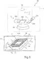
- Fig. 5 shows a processing machine 20, which also allows the production of a three-dimensional component 21 with a higher build-up rate.
- the processing machine 20 of Fig. 5 is different from the one in Fig. 4 Processing machine 20 shown essentially in that the irradiation device 1 has no beam shaping device.
- the laser beam 3 generated by the beam source 2 is thus irradiated without changing its beam profile and thus with a typically circular or circular beam cross section or "spot" with the aid of the scanner device 15 onto the processing field 11, more precisely onto the uppermost powder layer 25 ,
- Fig. 6a shows a section of the uppermost powder layer 25 with a portion T a of a layer of the generated three-dimensional component 21 of Fig. 5 and with the laser beam 3, more precisely with its point-shaped beam profile.
- the laser beam 3 is moved with an oscillating movement in a first direction R1 (X direction) continuously and repeatedly over the powder layer 25, wherein a line-shaped irradiation region 30 is generated, in which the powder layer 25 is melted.
- the line-shaped irradiation area 30, which in Fig. 6a is first generated at an upper end of the portion T a is in a second, different from the first direction R2 along a in Fig. 6a indicated trajectory 31 moves over the powder layer 25 until the portion T a completely melted with the desired geometry and thus the first portion T a of the layer of the three-dimensional component 21 is completely made.
- the second direction R2, ie the feed direction corresponds at the upper end of the powder layer 25 to the (negative) Y direction of the machining field 11 and is also continuously rotated by 90 ° during the movement of the linear irradiation region 30, so that the second direction R2 on the right End of the subarea T a with the X direction of the irradiation field 11 matches.
- Fig. 6a is also indicated, during the movement of the line-shaped irradiation region 30 via the powder layer 25, the two directions R1, R2 are not necessarily aligned perpendicular to each other, but the angle at which the two directions R1, R2 are aligned with each other in the processing field 11 at vary the movement over the powder layer 25.
- the power of the laser beam 3 is preferably controlled during the oscillating movement in such a way that the area to be illuminated or the subarea T a undergoes a constant, constant energy input.
- the power in the movement along the trajectory 31 is lowered in positive X and Y directions and increased in negative X and Y directions.
- the rotary drives 23a, 23b of the two scanner mirrors 22a, 22b are suitably controlled with the aid of the control device 16 in order to position the laser beam 3 in the processing field 11 of the scanner device 15 appropriately.
- the rotary actuators 23a, 23b can be driven to generate the oscillating movement with a high frequency in order to achieve an oscillation frequency of, for example, more than about 1 kHz.
- the laser beam 3 can be moved in particular in the processing field 11 in such a way that the line-shaped irradiation area 30 can be aligned or rotated practically as desired and also the (double) amplitude of the oscillating movement, i. the length L of the line-shaped irradiation area 30, can be varied over a comparatively large value range, which of course is limited by the size of the processing field 11 of the scanner device 15.
- the control device 16 accesses data on the (two-dimensional) geometry of the three-dimensional component 21 to be generated on the respective powder layer 25 to be irradiated, which are stored in a memory device or which are predetermined by a programming system.
- the two edges 32a, b of the produced portion T a which in the movement of the two ends of the line-shaped irradiation region 30 along the in Fig. 6a, b shown trajectory 31, a high smoothness, ie they correspond with a high resolution of the desired contour of the edge of the produced portion T a .
- the high resolution is achieved by changing the orientation as well as by changing the length L of the line-shaped irradiation area 30 during the movement along the path curve 31.
- One or possibly both edges 32a, b of the subregion T a may coincide with a contour of the component 21 to be produced.
- one or both edges 32 a, b of the subarea T a may not match the contour of the component 21, since laterally adjoining the respective edge 32 a, b may be another subregion of the component 21 to be produced followed.
- Fig. 6b shows how Fig. 6a the production of the portion T a of the layer of the three-dimensional component 21, wherein in Fig. 6b However, in contrast to Fig. 6a not one, but three laser beams 3a-c are used to generate the line-shaped irradiation area 30.
- Each of the three laser beams 3a-c carries out an oscillating movement which forms first, second and third sections 30a-c of the line-shaped irradiation area 30.
- the three sections 30a-c, the line-shaped irradiation area 30th form, directly adjacent to each other and have the same length L1 (corresponding to twice the amplitude of the oscillating motion) on.
- L1 corresponding to twice the amplitude of the oscillating motion
- the three laser beams 3a-c are independently movable over the powder layer 25 in the example shown.
- the scanner device 15 may comprise three pairs of scanner mirrors 22a, 22b each serving as two-dimensional scanners for moving a respective laser beam 3a-c over the powder layer 25. *** " It is understood that two or more than three laser beams 3a-c can be moved in this way independently of one another via the powder layer 25 or via the processing field 11.
- diffractive, optionally switchable optical elements can also be used to produce two or more laser beams 3a-c to move independently over the powder layer 25.
- two or more laser beams 3a-c can be moved independently of each other via the powder layer 25, they can be moved as in FIG Fig. 6b is shown on the one hand used for the joint production of a linear irradiation area 30.
- the two or more laser beams 3a-c on the other hand can also be used to independently different subregions T 1a ,..., T 1d, T 2 of the powder layer 25 (see FIG. Fig.
- the respective laser beam 3a-c does not perform an oscillating movement.
- the use of a plurality of laser beams 3a-c thus significantly increases the flexibility in the production of different three-dimensional components 21.
- Fig. 6b shown line-shaped irradiation area 30 can be generated in different ways by means of two or more laser beams 3a, 3b, to an influence on the stability of the melt in the sense of a Schmelzbadberuhist or an effect on the homogeneity of the melt to take, and possibly to increase the build-up rate by the length L of the line-shaped irradiation region 30 and the molten bath is increased.
- Fig. 7a FIG. 12 shows the generation of the line-shaped irradiation area 30 using two laser beams 3a, 3b which are analogous to FIG Fig. 6b produce a respective portion 30a, 30b of identical length L1, each performing an oscillating motion.
- FIG. 12 shows a case where the two portions 30a, 30b partially overlap in a range that is about 10% of the length L1.
- FIG. 7c FIG. 12 shows a case where the two portions 30a, 30b have different lengths L1, L2 to form the line-shaped irradiation area 30 in common. It is understood that the two sections 30a, 30b may possibly completely (100%) overlap, wherein in principle any value for the overlap (ie between 0% and 100%) is possible.
- Fig. 8a, b show the case of the linear irradiation area of Fig. 7a in which the two sections 30a, b do not overlap and have an identical length L1.
- the two sections 30a, b have a constant phase relationship, ie the oscillating movement of the respective laser beams 3a, 3b takes place with the same oscillation frequency.
- Fig. 8a shows the case in which the two laser beams 3a, 3b are moved in opposite directions
- Fig. 8b shows the case where the two laser beams 3a, 3b are moved in the same direction. It is understood that other phase relationships between the oscillating movements of the two laser beams 3a, 3b are possible.
- Fig. 9 finally shows the different directions of rotation of the oscillating movement of the two laser beams 3a, 3b in the opposite movement of Fig. 8a .
- the laser beams 3a, 3b as in Fig. 8a, b is oscillated along a common line and that only to illustrate the sense of rotation of the oscillating motion in Fig. 9 a meandering movement is shown.
- a fixed phase relationship between the oscillating movements of the two laser beams 3a, 3b does not necessarily have to exist, but that the oscillation frequencies of the two laser beams 3a, 3b are optionally chosen differently can be.
- the frequency of the oscillating movement of the at least one laser beam 3, 3a-c and thus the over a period averaged speed v1 in the first direction R1 (see. Fig. 6b ) used to generate the line-shaped irradiation area 30 is significantly larger than the feed speed v2, that is, the speed in the second direction R2.
- the speed v1 of the oscillating motion is at least ten times as large, preferably at least twenty times as large as the feed speed v2.
- the movement of the laser beam or beams 3, 3a-c for producing the three-dimensional component 21 or for producing a respective layer or partial region T a of a respective layer of the component 21 is controlled by the control device 16.
- the control device 16 can, as in Fig. 5 is shown to be disposed within the irradiation device 1, but it is also possible that it is arranged outside of the irradiation device 1 and communicates via a wireless or wired connection with the scanner device 15 and with other components of the irradiation device 1 and the processing machine 20.
Landscapes
- Optics & Photonics (AREA)
- Physics & Mathematics (AREA)
- Engineering & Computer Science (AREA)
- Materials Engineering (AREA)
- Chemical & Material Sciences (AREA)
- Mechanical Engineering (AREA)
- Plasma & Fusion (AREA)
- Manufacturing & Machinery (AREA)
- Health & Medical Sciences (AREA)
- Toxicology (AREA)
- General Health & Medical Sciences (AREA)
- Powder Metallurgy (AREA)
- Laser Beam Processing (AREA)
Claims (15)
- Dispositif d'irradiation (1) pour une machine d'usinage (20) destinée à la production de composants tridimensionnels (21) par irradiation de couches de poudre (25) au moyen d'un faisceau à haute énergie, en particulier au moyen d'un faisceau laser (3), le dispositif d'irradiation (1) comprenant :un dispositif de mise en forme de faisceau (14) pour mettre en forme un profil de faisceau (6, 6') du faisceau à haute énergie, lequel présente une longueur (L) dans une première direction (X) perpendiculaire à l'axe de faisceau (Z) du faisceau à haute énergie et une largeur (B), qui est inférieure à la longueur (L), dans une deuxième direction (Y) perpendiculaire à l'axe de faisceau (Z) du faisceau à haute énergie etun dispositif de balayage (15) pour orienter le faisceau à haute énergie sur une position (XP, YP) dans un champ d'usinage (11) du dispositif de balayage (15) pour irradier une couche de poudre (25) au moyen du faisceau à haute énergie, le dispositif d'irradiation (1) étant conçu pour modifier la longueur (L) et/ou la largeur (B) du profil de faisceau (6, 6') du faisceau à haute énergie dans le champ d'usinage (11) en fonction de la position (XP, YP) du faisceau à haute énergie dans le champ d'usinage (11),caractérisé en ceque le dispositif de mise en forme de faisceau (14) présente au moins un premier télescope de faisceau réglable (9) pour modifier la longueur (L) du profil de faisceau (6, 6') et au moins un deuxième télescope de faisceau réglable (12) pour modifier la largeur (B) du profil de faisceau (6, 6') indépendamment de la longueur (L) du profil de faisceau (6, 6').
- Dispositif d'irradiation selon la revendication 1, dans lequel au moins un premier et/ou au moins un deuxième télescope de faisceau (9, 12) présente au moins une lentille, de préférence une lentille cylindrique (10b, 13a, 13b), déplaçable dans la direction de l'axe de faisceau (Z) du faisceau à haute énergie.
- Dispositif d'irradiation selon la revendication 1 ou 2, dans lequel le dispositif de mise en forme de faisceau (14) est conçu pour mettre en forme un profil de faisceau (6, 6') du faisceau à haute énergie dont la longueur (L) et la largeur (B) coïncident.
- Dispositif d'irradiation selon l'une des revendications précédentes, lequel est conçu pour modifier l'orientation de la première direction (X) et de la deuxième direction (Y) du profil de faisceau (6, 6') dans un plan (XY) perpendiculaire à l'axe de faisceau (Z) du faisceau à haute énergie en fonction de la position (XP, YP) du faisceau à haute énergie dans le champ d'usinage (11).
- Dispositif d'irradiation selon la revendication 4, lequel est conçu pour faire tourner le profil de faisceau (6, 6') du faisceau à haute énergie autour de l'axe de faisceau (Z) du faisceau à haute énergie.
- Dispositif d'irradiation selon la revendication 5, dans lequel ledit au moins un premier et/ou deuxième télescope de faisceau (9, 12) est monté rotatif autour de l'axe de faisceau (Z) du faisceau à haute énergie et dans lequel le dispositif d'irradiation (1) présente au moins un entraînement (17) pour faire tourner ledit au moins un premier et/ou deuxième télescope de faisceau (9, 12) autour de l'axe de faisceau (Z).
- Dispositif d'irradiation selon l'une des revendications précédentes, comprenant en outre : un dispositif de collimation (4) disposé devant ledit au moins un premier et deuxième télescope de faisceau (9, 12) dans le trajet de faisceau du faisceau à haute énergie pour collimater le faisceau à haute énergie.
- Dispositif d'irradiation selon l'une des revendications précédentes, dans lequel le dispositif de mise en forme de faisceau (14) présente au moins un autre élément optique (19, 7) pour une mise en forme supplémentaire du profil de faisceau (6, 6').
- Dispositif d'irradiation selon l'une des revendications précédentes, comprenant en outre : un objectif (24) pour focaliser le faisceau à haute énergie lorsqu'il est orienté sur la position (XP, YP) dans le champ d'usinage (11).
- Dispositif d'irradiation selon l'une des revendications précédentes, comprenant en outre : une source de faisceau, en particulier une source laser (2), pour générer le faisceau à haute énergie.
- Dispositif d'irradiation selon l'une des revendications précédentes, comprenant en outre : un dispositif de commande (16) qui est conçu pour commander le dispositif de mise en forme de faisceau (14) afin de commander la longueur (L) et/ou la largeur (B) du profil de faisceau (6, 6') et de préférence l'orientation de la première direction (X) et de la deuxième direction (Y) du profil de faisceau (6, 6') en fonction de la position (XP, YP) du faisceau à haute énergie dans le champ d'usinage (11).
- Dispositif d'irradiation selon la revendication 11, dans lequel le dispositif de commande (16) est conçu pour commander le dispositif de mise en forme de faisceau (14) afin d'irradier au moins une première zone partielle (T1a, ...., T1d) du champ d'usinage (11) au moyen du faisceau à haute énergie pour produire une couche du composant tridimensionnel (21) avec un profil de faisceau (6, 6') dont la longueur (L) est supérieure à sa largeur (B), et d'irradier au moins une deuxième zone partielle (T2) du champ d'usinage (11) à irradier au moyen du faisceau à haute énergie pour produire la même couche du composant tridimensionnel (21) avec un profil de faisceau (6, 6') dont la longueur (L) et la largeur (B) coïncident.
- Machine d'usinage (20) destinée à la production de composants tridimensionnels (21) par irradiation de couches de poudre (25) au moyen d'un faisceau à haute énergie, en particulier au moyen d'un faisceau laser (3), comprenant :
un dispositif d'irradiation (1) selon l'une des revendications précédentes et une chambre d'usinage (27) avec un support (26) pour appliquer les couches de poudre (25). - Procédé de production d'une couche d'un composant tridimensionnel (21) par irradiation d'une couche de poudre (25) au moyen d'un faisceau à haute énergie, en particulier au moyen d'un faisceau laser (3), comprenant les étapes consistant à :irradier la couche de poudre (25) au moyen du faisceau à haute énergie dans un champ d'usinage (11) pour produire la couche du composant tridimensionnel (21),dans lequel un profil de faisceau (6, 6') du faisceau à haute énergie présente une longueur (L) dans une première direction (X) perpendiculaire à l'axe de faisceau (Z) du faisceau à haute énergie et une largeur (B), qui est inférieure à la longueur (L), dans une deuxième direction (Y) perpendiculaire à l'axe de faisceau (Z) du faisceau à haute énergie, et dans lequel la longueur (L) et la largeur (B) du profil de faisceau (6, 6') du faisceau à haute énergie dans le champ d'usinage (11) et de préférence une orientation de la première direction (X) et la deuxième direction (Y) du profil de faisceau (6, 6') sont modifiées en fonction de la position (Xp, Yp) du faisceau à haute énergie dans le champ d'usinage (11),caractérisé en ceque la longueur (L) du profil de faisceau (6, 6') du faisceau à haute énergie dans le champ d'usinage (11) est modifiée au moyen d'au moins un premier télescope de faisceau réglable (9) et la largeur (B) du profil de faisceau (6, 6') du faisceau à haute énergie dans le champ d'usinage (11) est modifiée au moyen d'au moins un deuxième télescope de faisceau réglable (9) indépendamment de la longueur (L) du profil de faisceau (6, 6') du faisceau à haute énergie.
- Procédé selon la revendication 14, dans lequel la couche de poudre (25) est irradiée dans au moins une première zone partielle (T1a, ..., T1d) avec un profil de faisceau (6, 6') dont la longueur (L) est supérieure à sa largeur (B) et dans lequel la couche de poudre (25) est irradiée dans au moins une deuxième zone partielle (T2) avec un profil de faisceau (6, 6') dont la longueur (L) et la largeur (B) coïncident.
Applications Claiming Priority (2)
| Application Number | Priority Date | Filing Date | Title |
|---|---|---|---|
| DE102015202347.8A DE102015202347A1 (de) | 2015-02-10 | 2015-02-10 | Bestrahlungseinrichtung, Bearbeitungsmaschine und Verfahren zum Herstellen einer Schicht eines dreidimensionalen Bauteils |
| PCT/EP2016/052772 WO2016128430A1 (fr) | 2015-02-10 | 2016-02-10 | Dispositif d'irradiation, machine de traitement et procédé de fabrication d'une couche ou d'une sous-zone d'une couche d'une pièce tridimensionnelle |
Publications (2)
| Publication Number | Publication Date |
|---|---|
| EP3256285A1 EP3256285A1 (fr) | 2017-12-20 |
| EP3256285B1 true EP3256285B1 (fr) | 2019-04-17 |
Family
ID=55442770
Family Applications (1)
| Application Number | Title | Priority Date | Filing Date |
|---|---|---|---|
| EP16706552.3A Active EP3256285B1 (fr) | 2015-02-10 | 2016-02-10 | Dispositif d'irradiation, machine de traitement et procédé de fabrication d'une couche ou d'une sous-zone d'une couche d'une pièce tridimensionnelle |
Country Status (5)
| Country | Link |
|---|---|
| US (1) | US11135680B2 (fr) |
| EP (1) | EP3256285B1 (fr) |
| CN (1) | CN108883499B (fr) |
| DE (1) | DE102015202347A1 (fr) |
| WO (1) | WO2016128430A1 (fr) |
Families Citing this family (38)
| Publication number | Priority date | Publication date | Assignee | Title |
|---|---|---|---|---|
| WO2017091505A1 (fr) | 2015-11-23 | 2017-06-01 | Nlight, Inc. | Commande temporelle à échelle fine pour usinage de matériaux au laser |
| KR101800667B1 (ko) * | 2016-12-23 | 2017-12-20 | (주)레이 | Lcd 방식 3d 프린터 |
| DE102017001658A1 (de) | 2017-02-21 | 2018-08-23 | Precitec Gmbh & Co. Kg | Vorrichtung zur materialbearbeitung mit einem laserstrahl entlang einer bearbeitungsrichtung und verfahren zur materialbearbeitung mit einem laserstrahl |
| US11389896B2 (en) * | 2017-04-04 | 2022-07-19 | Nlight, Inc. | Calibration test piece for galvanometric laser calibration |
| EP4035803A1 (fr) * | 2017-05-22 | 2022-08-03 | NLIGHT, Inc. | Commande temporelle à échelle fine pour traitement de matériau laser |
| DE102017212565A1 (de) | 2017-07-21 | 2019-01-24 | Trumpf Laser- Und Systemtechnik Gmbh | Verfahren zum Erzeugen eines zusammenhängenden Flächenbereichs, Bestrahlungseinrichtung und Bearbeitungsmaschine |
| WO2019034259A1 (fr) | 2017-08-18 | 2019-02-21 | Fraunhofer-Gesellschaft zur Förderung der angewandten Forschung e. V. | Procédé d'usinage d'une couche de matériau avec un rayonnement énergétique à distribution d'énergie variable |
| DE102017127148A1 (de) * | 2017-11-17 | 2019-05-23 | Eos Gmbh Electro Optical Systems | Bestrahlungsstreifensortierung |
| US10821551B2 (en) * | 2018-01-26 | 2020-11-03 | General Electronic Company | Systems and methods for dynamic shaping of laser beam profiles in additive manufacturing |
| US10814429B2 (en) * | 2018-01-26 | 2020-10-27 | General Electric Company | Systems and methods for dynamic shaping of laser beam profiles for control of micro-structures in additively manufactured metals |
| US11224943B2 (en) * | 2018-03-07 | 2022-01-18 | Divergent Technologies, Inc. | Variable beam geometry laser-based powder bed fusion |
| WO2019179603A1 (fr) * | 2018-03-20 | 2019-09-26 | Robert Bosch Gmbh | Procédé et dispositif pour l'adaptation de la forme de faisceau et l'orientation de faisceau orientées sur le processus |
| DE102018219032A1 (de) * | 2018-08-17 | 2020-02-20 | Denise Bennewitz | Bauteiledruckverfahren und Vorrichtungen hierfür |
| EP3674029A1 (fr) | 2018-12-28 | 2020-07-01 | Etxe-Tar, S.A. | Procédé et système de chauffage d'un objet à l'aide d'un faisceau d'énergie |
| US11305366B2 (en) * | 2019-01-04 | 2022-04-19 | Lincoln Global, Inc. | Systems and methods providing dynamic bead spacing and weave fill in additive manufacturing |
| US11839914B1 (en) | 2019-01-31 | 2023-12-12 | Freeform Future Corp. | Process monitoring and feedback for metal additive manufacturing using powder-bed fusion |
| US11525968B2 (en) * | 2019-03-14 | 2022-12-13 | Nlight, Inc. | Calibration validation using geometric features in galvanometric scanning systems |
| US11579440B2 (en) | 2019-03-14 | 2023-02-14 | Nlight, Inc. | Focus assessment in dynamically focused laser system |
| CN110523978A (zh) * | 2019-08-02 | 2019-12-03 | 南京中科煜宸激光技术有限公司 | 提升送粉式激光增材制造效率的工艺 |
| JP7385743B2 (ja) * | 2019-08-27 | 2023-11-22 | エスエルエム ソルーションズ グループ アーゲー | 機器と装置 |
| DE102019128344A1 (de) * | 2019-10-21 | 2021-04-22 | Carl Zeiss Ag | Verfahren zum additiven herstellen eines objekts und herstellungsvorrichtung |
| US20230061492A1 (en) * | 2020-01-21 | 2023-03-02 | Ipg Photonics Corporation | System and method for laser metal powder deposition |
| CN113399825B (zh) * | 2020-03-17 | 2022-05-20 | 深圳市联赢激光股份有限公司 | 一种激光装置 |
| FR3110096B1 (fr) * | 2020-05-12 | 2023-03-17 | Addup | Procédé de fabrication additive d’un objet à partir d’une couche de poudre |
| DE102021119195A1 (de) | 2021-07-23 | 2023-01-26 | Trumpf Laser Gmbh | Verfahren und Vorrichtung zur Werkstückbearbeitung mit einem, durch eine Scanneroptik geführten, verbreiterten Laserstrahl |
| WO2023188082A1 (fr) * | 2022-03-30 | 2023-10-05 | 株式会社ニコン | Dispositif de traitement |
| EP4257960A1 (fr) * | 2022-04-06 | 2023-10-11 | TRUMPF Additive Manufacturing Italia S.r.l. | Procédé de surveillance d'au moins une surface d'un élément optique dans un appareil de fabrication additive et appareil de fabrication additive d'un objet |
| US20240017481A1 (en) * | 2022-07-15 | 2024-01-18 | General Electric Company | Additive manufacturing methods and systems |
| DE102022121238A1 (de) | 2022-08-23 | 2024-02-29 | Trumpf Laser- Und Systemtechnik Gmbh | Fertigungsvorrichtung und Verfahren zum additiven Fertigen von Bauteilen aus einem Pulvermaterial und Verfahren zum Ermitteln einer Korrekturfunktion für eine solche Fertigungsvorrichtung oder ein solches Verfahren |
| GB202218751D0 (en) | 2022-12-13 | 2023-01-25 | Renishaw Plc | Powder bed fusion apparatus and methods |
| DE102022133073A1 (de) * | 2022-12-13 | 2024-06-13 | Trumpf Laser Ag | Laserbearbeitungsanlage zur Bearbeitung eines Werkstücks mittels eines Ausgangslaserstrahls |
| US11977316B1 (en) | 2023-06-10 | 2024-05-07 | IntraAction Corp. | Thin film acousto-optic device and methods of fabrication |
| US11988941B1 (en) | 2023-06-10 | 2024-05-21 | IntraAction Corp. | Fiber coupled multi-frequency shifter |
| US11788953B1 (en) | 2023-06-10 | 2023-10-17 | IntraAction Corp. | Isotope isolation |
| US11953668B1 (en) | 2023-06-10 | 2024-04-09 | IntraAction Corp. | Tunable filter for microscope |
| US11829011B1 (en) | 2023-06-10 | 2023-11-28 | IntraAction Corp. | Robotic system for acousto-optic transducer bonding |
| US11949207B1 (en) | 2023-06-10 | 2024-04-02 | IntraAction Inc. | AOD device |
| US11828846B1 (en) | 2023-06-10 | 2023-11-28 | IntraAction Corp. | Lidar acousto-optic device and methods of fabrication |
Family Cites Families (62)
| Publication number | Priority date | Publication date | Assignee | Title |
|---|---|---|---|---|
| US5155324A (en) * | 1986-10-17 | 1992-10-13 | Deckard Carl R | Method for selective laser sintering with layerwise cross-scanning |
| US4863538A (en) | 1986-10-17 | 1989-09-05 | Board Of Regents, The University Of Texas System | Method and apparatus for producing parts by selective sintering |
| JPS63224889A (ja) * | 1987-03-13 | 1988-09-19 | Toyota Motor Corp | レ−ザ肉盛溶接方法 |
| JPH02142690A (ja) * | 1988-11-21 | 1990-05-31 | Mitsubishi Electric Corp | レーザ溶接方法 |
| US5753171A (en) * | 1994-05-13 | 1998-05-19 | Eos Gmbh Electro Optical Systems | Method and apparatus for producing a three-dimensional object |
| DE19606128A1 (de) * | 1996-02-20 | 1997-08-21 | Eos Electro Optical Syst | Vorrichtung und Verfahren zum Herstellen eines dreidimensionalen Objektes |
| US6132667A (en) * | 1999-02-08 | 2000-10-17 | 3D Systems, Inc. | Stereolithographic method and apparatus with enhanced control of prescribed stimulation production and application |
| DE19953000C2 (de) | 1999-11-04 | 2003-04-10 | Horst Exner | Verfahren und Einrichtung zur schnellen Herstellung von Körpern |
| JP2002144061A (ja) * | 2000-11-02 | 2002-05-21 | Mitsubishi Heavy Ind Ltd | 加工装置 |
| US6426840B1 (en) * | 2001-02-23 | 2002-07-30 | 3D Systems, Inc. | Electronic spot light control |
| US20030044647A1 (en) * | 2001-09-05 | 2003-03-06 | Iraj Kavosh | Laser textured magnetic disk |
| JP2005522342A (ja) * | 2002-04-15 | 2005-07-28 | シーメンス アクチエンゲゼルシヤフト | 単結晶構造の製造方法 |
| SE524421C2 (sv) * | 2002-12-19 | 2004-08-10 | Arcam Ab | Anordning samt metod för framställande av en tredimensionell produkt |
| WO2004076102A1 (fr) * | 2003-02-25 | 2004-09-10 | Matsushita Electric Works, Ltd. | Procede et dispositif de fabrication d'une structure tridimensionnelle |
| DE102004009127A1 (de) | 2004-02-25 | 2005-09-15 | Bego Medical Ag | Verfahren und Vorrichtung zum Herstellen von Produkten durch Sintern und/oder Schmelzen |
| US8071912B2 (en) * | 2005-11-16 | 2011-12-06 | Technolines, Lp | Engineered wood fiber product substrates and their formation by laser processing |
| KR101371265B1 (ko) * | 2005-12-16 | 2014-03-07 | 가부시키가이샤 한도오따이 에네루기 켄큐쇼 | 레이저 조사 장치, 레이저 조사 방법, 및 반도체 장치 제조방법 |
| US20090206065A1 (en) * | 2006-06-20 | 2009-08-20 | Jean-Pierre Kruth | Procedure and apparatus for in-situ monitoring and feedback control of selective laser powder processing |
| GB0816308D0 (en) * | 2008-09-05 | 2008-10-15 | Mtt Technologies Ltd | Optical module |
| EP2424706B2 (fr) * | 2009-04-28 | 2022-02-09 | BAE Systems PLC | Procédé de fabrication d'une pièce par rechargement par couches successives |
| BR112013009155B1 (pt) | 2011-01-28 | 2018-02-06 | Arcam Ab | Method for production of a three-dimensional body. |
| GB2490143B (en) * | 2011-04-20 | 2013-03-13 | Rolls Royce Plc | Method of manufacturing a component |
| DE102011105045B3 (de) * | 2011-06-20 | 2012-06-21 | Fraunhofer-Gesellschaft zur Förderung der angewandten Forschung e.V. | Verfahren zur Herstellung eines Bauteils mittels selektivem Laserschmelzen |
| DE102011119319A1 (de) | 2011-11-24 | 2013-05-29 | Slm Solutions Gmbh | Optische Bestrahlungsvorrichtung für eine Anlage zur Herstellung von dreidimensionalen Werkstücken durch Bestrahlen von Pulverschichten eines Rohstoffpulvers mit Laserstrahlung |
| DE102012202487A1 (de) * | 2012-02-17 | 2013-08-22 | Evonik Industries Ag | Verfahren zum Aufschmelzen/Sintern von Pulverpartikeln zur schichtweisen Herstellung von dreidimensionalen Objekten |
| JP5599957B2 (ja) * | 2012-03-09 | 2014-10-01 | パナソニック株式会社 | 三次元形状造形物の製造方法 |
| US9272365B2 (en) * | 2012-09-12 | 2016-03-01 | Siemens Energy, Inc. | Superalloy laser cladding with surface topology energy transfer compensation |
| GB201209415D0 (en) * | 2012-05-28 | 2012-07-11 | Renishaw Plc | Manufacture of metal articles |
| DE102012011418A1 (de) * | 2012-06-08 | 2013-12-12 | Universität Rostock | Stereolithographie- System |
| FR2994113B1 (fr) * | 2012-07-31 | 2017-10-06 | Michelin & Cie | Machine et procede pour la fabrication additive a base de poudre |
| EP2737965A1 (fr) * | 2012-12-01 | 2014-06-04 | Alstom Technology Ltd | Procédé de fabrication d'un composant métallique par fabrication laser d'un additif |
| DE102013205724A1 (de) * | 2013-03-28 | 2014-10-02 | Eos Gmbh Electro Optical Systems | Verfahren und Vorrichtung zum Herstellen eines dreidimensionalen Objekts |
| WO2014176536A1 (fr) * | 2013-04-26 | 2014-10-30 | United Technologies Corporation | Système de fusion sélective par laser |
| EP3007879B1 (fr) * | 2013-06-10 | 2019-02-13 | Renishaw Plc. | Appareil et procédé de solidification sélective par laser |
| US10350683B2 (en) * | 2013-10-02 | 2019-07-16 | Grid Logic Incorporated | Multiple flux concentrator heating |
| DE102013017792A1 (de) * | 2013-10-28 | 2015-04-30 | Cl Schutzrechtsverwaltungs Gmbh | Verfahren zum Herstellen eines dreidimensionalen Bauteils |
| DE102013226298A1 (de) * | 2013-12-17 | 2015-06-18 | MTU Aero Engines AG | Belichtung bei generativer Fertigung |
| US9789563B2 (en) * | 2013-12-20 | 2017-10-17 | Arcam Ab | Method for additive manufacturing |
| EP2893994B1 (fr) * | 2014-01-14 | 2020-07-15 | General Electric Technology GmbH | Procédé de fabrication d'un composant métallique ou céramique par fusion laser sélective |
| CN106068165B (zh) * | 2014-03-18 | 2018-05-04 | 株式会社东芝 | 层叠造型装置以及层叠造型物的制造方法 |
| CA2958107C (fr) * | 2014-08-20 | 2023-04-11 | Etxe-Tar, S.A. | Procede et systeme pour fabrication additive a l'aide d'un faisceau de lumiere |
| CN104190931B (zh) * | 2014-09-09 | 2016-10-05 | 华中科技大学 | 一种高效高精度复合増材制造方法及装置 |
| US20180272611A1 (en) * | 2015-01-07 | 2018-09-27 | Eos Gmbh Electro Optical Systems | Device and generative layer-building process for producing a three-dimensional object by multiple beams |
| WO2016121013A1 (fr) * | 2015-01-28 | 2016-08-04 | 株式会社日立製作所 | Matériau de poudre de résine, procédé de moulage de poudre au laser et dispositif |
| JP6770245B2 (ja) * | 2015-10-15 | 2020-10-14 | セイコーエプソン株式会社 | 三次元造形物の製造方法及び三次元造形物の製造装置 |
| DE102015224130A1 (de) * | 2015-12-03 | 2017-06-08 | MTU Aero Engines AG | Ermitteln einer Scangeschwindigkeit einer Fertigungsvorrichtung zum additiven Herstellen eines Bauteils |
| US10183330B2 (en) * | 2015-12-10 | 2019-01-22 | Vel03D, Inc. | Skillful three-dimensional printing |
| GB201600645D0 (en) * | 2016-01-13 | 2016-02-24 | Rolls Royce Plc | Improvements in additive layer manufacturing methods |
| JP6732502B2 (ja) * | 2016-03-31 | 2020-07-29 | キヤノン株式会社 | 三次元造形方法、プログラム、記録媒体、及び三次元造形装置 |
| JP6655714B2 (ja) * | 2016-04-13 | 2020-02-26 | 株式会社日立製作所 | 樹脂造形物およびレーザ粉末積層造形装置 |
| US10518478B2 (en) * | 2016-05-10 | 2019-12-31 | Hamilton Sundstrand Corporation | Additive manufacturing systems and methods |
| US20180126462A1 (en) * | 2016-11-07 | 2018-05-10 | Velo3D, Inc. | Gas flow in three-dimensional printing |
| DE102016222187A1 (de) * | 2016-11-11 | 2018-05-17 | Trumpf Laser- Und Systemtechnik Gmbh | Verfahren zum Bestimmen eines Strahlprofils eines Laserstrahls und Bearbeitungsmaschine |
| DE102016222186B3 (de) * | 2016-11-11 | 2018-04-12 | Trumpf Laser- Und Systemtechnik Gmbh | Verfahren zum Kalibrieren zweier Scannereinrichtungen jeweils zur Positionierung eines Laserstrahls in einem Bearbeitungsfeld und Bearbeitungsmaschine zum Herstellen von dreidimensionalen Bauteilen durch Bestrahlen von Pulverschichten |
| DE102016223215A1 (de) * | 2016-11-23 | 2018-05-24 | Trumpf Laser- Und Systemtechnik Gmbh | Bestrahlungseinrichtung und Bearbeitungsmaschine damit |
| US20180154443A1 (en) * | 2016-12-06 | 2018-06-07 | Velo3D, Inc. | Optics, detectors, and three-dimensional printing |
| US20180186082A1 (en) * | 2017-01-05 | 2018-07-05 | Velo3D, Inc. | Optics in three-dimensional printing |
| DE102017200152A1 (de) * | 2017-01-09 | 2018-07-12 | Ford Global Technologies, Llc | Additives Fertigungsverfahren |
| US10442003B2 (en) * | 2017-03-02 | 2019-10-15 | Velo3D, Inc. | Three-dimensional printing of three-dimensional objects |
| US10821551B2 (en) * | 2018-01-26 | 2020-11-03 | General Electronic Company | Systems and methods for dynamic shaping of laser beam profiles in additive manufacturing |
| US10695867B2 (en) * | 2018-03-08 | 2020-06-30 | General Electric Company | Controlling microstructure of selected range of layers of object during additive manufacture |
| US10974456B2 (en) * | 2018-03-23 | 2021-04-13 | Lawrence Livermore National Security, Llc | Additive manufacturing power map to mitigate defects |
-
2015
- 2015-02-10 DE DE102015202347.8A patent/DE102015202347A1/de not_active Withdrawn
-
2016
- 2016-02-10 EP EP16706552.3A patent/EP3256285B1/fr active Active
- 2016-02-10 WO PCT/EP2016/052772 patent/WO2016128430A1/fr active Application Filing
-
2017
- 2017-02-07 CN CN201780022630.0A patent/CN108883499B/zh active Active
-
2018
- 2018-08-10 US US16/100,572 patent/US11135680B2/en active Active
Non-Patent Citations (1)
| Title |
|---|
| None * |
Also Published As
| Publication number | Publication date |
|---|---|
| US20180345413A1 (en) | 2018-12-06 |
| DE102015202347A1 (de) | 2016-08-11 |
| EP3256285A1 (fr) | 2017-12-20 |
| CN108883499B (zh) | 2021-07-06 |
| WO2016128430A1 (fr) | 2016-08-18 |
| CN108883499A (zh) | 2018-11-23 |
| US11135680B2 (en) | 2021-10-05 |
Similar Documents
| Publication | Publication Date | Title |
|---|---|---|
| EP3256285B1 (fr) | Dispositif d'irradiation, machine de traitement et procédé de fabrication d'une couche ou d'une sous-zone d'une couche d'une pièce tridimensionnelle | |
| EP3866999B1 (fr) | Procédé et dispositif de fabrication d'une pièce tridimensionnelle | |
| EP3414044B1 (fr) | Procédé de production d'une partie d'une couche d'un composant tridimensionnel | |
| EP3519126B1 (fr) | Fabrication de pièces tridimensionnelles au moyen d'une pluralité d'unités de rayonnement | |
| EP3655183A1 (fr) | Procédé pour la génération d'une région de surface cohérente, dispositif d'irradiation et machine d'usinage | |
| EP4185430A1 (fr) | Procédé de déplacement brusque d'un faisceau d'énergie continu et dispositif de fabrication | |
| EP2314412A2 (fr) | Dispositif de traitement au laser et procédé de fabrication d'une surface sur une ébauche | |
| WO2016120327A1 (fr) | Dispositif d'usinage de matériau par rayonnement laser | |
| EP4263116A1 (fr) | Dispositif de traitement d'un matériau | |
| DE102020213711A1 (de) | Planungseinrichtung und Verfahren zur Planung einer lokal selektiven Bestrahlung eines Arbeitsbereichs mit einem Energiestrahl, Computerprogrammprodukt zur Durchführung eines solchen Verfahrens, Fertigungseinrichtung mit einer solchen Planungseinrichtung, und Verfahren zum additiven Fertigen eines Bauteils aus einem Pulvermaterial | |
| WO2019081381A1 (fr) | Dispositif d'irradiation, machine d'usinage et procédé pour irradier une zone d'usinage égale | |
| WO2019034259A1 (fr) | Procédé d'usinage d'une couche de matériau avec un rayonnement énergétique à distribution d'énergie variable | |
| DE112022004908T5 (de) | Vorrichtung zum additiven Herstellen und Verfahren zum additiven Herstellen | |
| DE10324439B4 (de) | Verfahren und Vorrichtung zur Herstellung eines Gesenks | |
| DE102018106579A1 (de) | Verfahren zur Bearbeitung eines Werkstücks mittels Bestrahlung mit Laserstrahlung sowie Vorrichtung hierzu | |
| WO2022074094A1 (fr) | Appareil et procédé pour générer une ligne laser définie sur un plan de travail | |
| DE102021129468A1 (de) | Verfahren, Planungsvorrichtung und Computerprogrammprodukt zum Planen einer lokal selektiven Bestrahlung eines Arbeitsbereichs mit einem Energiestrahl, sowie Verfahren, Fertigungsvorrichtung und Computerprogrammprodukt zum additiven Fertigen von Bauteilen aus einem Pulvermaterial | |
| EP3837103A1 (fr) | Procédé d'impression de composants et dispositifs associés | |
| WO2022073785A1 (fr) | Exposition localement sélective d'une zone de travail par une forme de faisceau s'écartant de la forme circulaire | |
| WO2022188922A1 (fr) | Dispositif de miroir pour système de fabrication permettant la fabrication à base de faisceau laser, système et procédé de fabrication | |
| EP4200097A1 (fr) | Dispositif de planification, dispositif de fabrication, procédé et produit-programme informatique pour la fabrication additive de composants à partir d'un matériau en poudre | |
| WO2023078762A1 (fr) | Procédé, dispositif de planification et produit-programme informatique de planification d'une exposition localement sélective d'une zone de travail au rayonnement d'un faisceau d'énergie, et procédé, dispositif de production et produit-programme informatique pour la fabrication additive de composants à partir d'un matériau en poudre | |
| DE102020216123A1 (de) | Belichtungseinrichtung, Vorrichtung und Verfahren zur additiven Fertigung eines Werkstücks | |
| DE102022121239A1 (de) | Strahlweitenveränderungsvorrichtung, Fertigungsvorrichtung zum additiven Fertigen mit einer solchen Strahlweitenveränderungsvorrichtung, Verfahren zum additiven Fertigen mittels einer solchen Strahlweitenveränderungsvorrichtung und Verwendung einer solchen Strahlweitenveränderungsvorrichtung zum additiven Fertigen von Bauteilen |
Legal Events
| Date | Code | Title | Description |
|---|---|---|---|
| STAA | Information on the status of an ep patent application or granted ep patent |
Free format text: STATUS: THE INTERNATIONAL PUBLICATION HAS BEEN MADE |
|
| PUAI | Public reference made under article 153(3) epc to a published international application that has entered the european phase |
Free format text: ORIGINAL CODE: 0009012 |
|
| STAA | Information on the status of an ep patent application or granted ep patent |
Free format text: STATUS: REQUEST FOR EXAMINATION WAS MADE |
|
| 17P | Request for examination filed |
Effective date: 20170911 |
|
| AK | Designated contracting states |
Kind code of ref document: A1 Designated state(s): AL AT BE BG CH CY CZ DE DK EE ES FI FR GB GR HR HU IE IS IT LI LT LU LV MC MK MT NL NO PL PT RO RS SE SI SK SM TR |
|
| AX | Request for extension of the european patent |
Extension state: BA ME |
|
| DAV | Request for validation of the european patent (deleted) | ||
| DAX | Request for extension of the european patent (deleted) | ||
| GRAP | Despatch of communication of intention to grant a patent |
Free format text: ORIGINAL CODE: EPIDOSNIGR1 |
|
| STAA | Information on the status of an ep patent application or granted ep patent |
Free format text: STATUS: GRANT OF PATENT IS INTENDED |
|
| INTG | Intention to grant announced |
Effective date: 20181105 |
|
| GRAS | Grant fee paid |
Free format text: ORIGINAL CODE: EPIDOSNIGR3 |
|
| GRAA | (expected) grant |
Free format text: ORIGINAL CODE: 0009210 |
|
| STAA | Information on the status of an ep patent application or granted ep patent |
Free format text: STATUS: THE PATENT HAS BEEN GRANTED |
|
| AK | Designated contracting states |
Kind code of ref document: B1 Designated state(s): AL AT BE BG CH CY CZ DE DK EE ES FI FR GB GR HR HU IE IS IT LI LT LU LV MC MK MT NL NO PL PT RO RS SE SI SK SM TR |
|
| REG | Reference to a national code |
Ref country code: GB Ref legal event code: FG4D Free format text: NOT ENGLISH |
|
| REG | Reference to a national code |
Ref country code: CH Ref legal event code: EP |
|
| REG | Reference to a national code |
Ref country code: DE Ref legal event code: R096 Ref document number: 502016004221 Country of ref document: DE |
|
| REG | Reference to a national code |
Ref country code: AT Ref legal event code: REF Ref document number: 1121017 Country of ref document: AT Kind code of ref document: T Effective date: 20190515 Ref country code: IE Ref legal event code: FG4D Free format text: LANGUAGE OF EP DOCUMENT: GERMAN |
|
| REG | Reference to a national code |
Ref country code: NL Ref legal event code: MP Effective date: 20190417 |
|
| REG | Reference to a national code |
Ref country code: LT Ref legal event code: MG4D |
|
| PG25 | Lapsed in a contracting state [announced via postgrant information from national office to epo] |
Ref country code: NL Free format text: LAPSE BECAUSE OF FAILURE TO SUBMIT A TRANSLATION OF THE DESCRIPTION OR TO PAY THE FEE WITHIN THE PRESCRIBED TIME-LIMIT Effective date: 20190417 |
|
| PG25 | Lapsed in a contracting state [announced via postgrant information from national office to epo] |
Ref country code: HR Free format text: LAPSE BECAUSE OF FAILURE TO SUBMIT A TRANSLATION OF THE DESCRIPTION OR TO PAY THE FEE WITHIN THE PRESCRIBED TIME-LIMIT Effective date: 20190417 Ref country code: LT Free format text: LAPSE BECAUSE OF FAILURE TO SUBMIT A TRANSLATION OF THE DESCRIPTION OR TO PAY THE FEE WITHIN THE PRESCRIBED TIME-LIMIT Effective date: 20190417 Ref country code: SE Free format text: LAPSE BECAUSE OF FAILURE TO SUBMIT A TRANSLATION OF THE DESCRIPTION OR TO PAY THE FEE WITHIN THE PRESCRIBED TIME-LIMIT Effective date: 20190417 Ref country code: FI Free format text: LAPSE BECAUSE OF FAILURE TO SUBMIT A TRANSLATION OF THE DESCRIPTION OR TO PAY THE FEE WITHIN THE PRESCRIBED TIME-LIMIT Effective date: 20190417 Ref country code: PT Free format text: LAPSE BECAUSE OF FAILURE TO SUBMIT A TRANSLATION OF THE DESCRIPTION OR TO PAY THE FEE WITHIN THE PRESCRIBED TIME-LIMIT Effective date: 20190817 Ref country code: AL Free format text: LAPSE BECAUSE OF FAILURE TO SUBMIT A TRANSLATION OF THE DESCRIPTION OR TO PAY THE FEE WITHIN THE PRESCRIBED TIME-LIMIT Effective date: 20190417 Ref country code: NO Free format text: LAPSE BECAUSE OF FAILURE TO SUBMIT A TRANSLATION OF THE DESCRIPTION OR TO PAY THE FEE WITHIN THE PRESCRIBED TIME-LIMIT Effective date: 20190717 Ref country code: ES Free format text: LAPSE BECAUSE OF FAILURE TO SUBMIT A TRANSLATION OF THE DESCRIPTION OR TO PAY THE FEE WITHIN THE PRESCRIBED TIME-LIMIT Effective date: 20190417 |
|
| PG25 | Lapsed in a contracting state [announced via postgrant information from national office to epo] |
Ref country code: BG Free format text: LAPSE BECAUSE OF FAILURE TO SUBMIT A TRANSLATION OF THE DESCRIPTION OR TO PAY THE FEE WITHIN THE PRESCRIBED TIME-LIMIT Effective date: 20190717 Ref country code: GR Free format text: LAPSE BECAUSE OF FAILURE TO SUBMIT A TRANSLATION OF THE DESCRIPTION OR TO PAY THE FEE WITHIN THE PRESCRIBED TIME-LIMIT Effective date: 20190718 Ref country code: LV Free format text: LAPSE BECAUSE OF FAILURE TO SUBMIT A TRANSLATION OF THE DESCRIPTION OR TO PAY THE FEE WITHIN THE PRESCRIBED TIME-LIMIT Effective date: 20190417 Ref country code: PL Free format text: LAPSE BECAUSE OF FAILURE TO SUBMIT A TRANSLATION OF THE DESCRIPTION OR TO PAY THE FEE WITHIN THE PRESCRIBED TIME-LIMIT Effective date: 20190417 Ref country code: RS Free format text: LAPSE BECAUSE OF FAILURE TO SUBMIT A TRANSLATION OF THE DESCRIPTION OR TO PAY THE FEE WITHIN THE PRESCRIBED TIME-LIMIT Effective date: 20190417 |
|
| PG25 | Lapsed in a contracting state [announced via postgrant information from national office to epo] |
Ref country code: IS Free format text: LAPSE BECAUSE OF FAILURE TO SUBMIT A TRANSLATION OF THE DESCRIPTION OR TO PAY THE FEE WITHIN THE PRESCRIBED TIME-LIMIT Effective date: 20190817 |
|
| REG | Reference to a national code |
Ref country code: DE Ref legal event code: R097 Ref document number: 502016004221 Country of ref document: DE |
|
| PG25 | Lapsed in a contracting state [announced via postgrant information from national office to epo] |
Ref country code: EE Free format text: LAPSE BECAUSE OF FAILURE TO SUBMIT A TRANSLATION OF THE DESCRIPTION OR TO PAY THE FEE WITHIN THE PRESCRIBED TIME-LIMIT Effective date: 20190417 Ref country code: DK Free format text: LAPSE BECAUSE OF FAILURE TO SUBMIT A TRANSLATION OF THE DESCRIPTION OR TO PAY THE FEE WITHIN THE PRESCRIBED TIME-LIMIT Effective date: 20190417 Ref country code: RO Free format text: LAPSE BECAUSE OF FAILURE TO SUBMIT A TRANSLATION OF THE DESCRIPTION OR TO PAY THE FEE WITHIN THE PRESCRIBED TIME-LIMIT Effective date: 20190417 Ref country code: CZ Free format text: LAPSE BECAUSE OF FAILURE TO SUBMIT A TRANSLATION OF THE DESCRIPTION OR TO PAY THE FEE WITHIN THE PRESCRIBED TIME-LIMIT Effective date: 20190417 Ref country code: SK Free format text: LAPSE BECAUSE OF FAILURE TO SUBMIT A TRANSLATION OF THE DESCRIPTION OR TO PAY THE FEE WITHIN THE PRESCRIBED TIME-LIMIT Effective date: 20190417 |
|
| PLBE | No opposition filed within time limit |
Free format text: ORIGINAL CODE: 0009261 |
|
| STAA | Information on the status of an ep patent application or granted ep patent |
Free format text: STATUS: NO OPPOSITION FILED WITHIN TIME LIMIT |
|
| PG25 | Lapsed in a contracting state [announced via postgrant information from national office to epo] |
Ref country code: SM Free format text: LAPSE BECAUSE OF FAILURE TO SUBMIT A TRANSLATION OF THE DESCRIPTION OR TO PAY THE FEE WITHIN THE PRESCRIBED TIME-LIMIT Effective date: 20190417 |
|
| 26N | No opposition filed |
Effective date: 20200120 |
|
| PG25 | Lapsed in a contracting state [announced via postgrant information from national office to epo] |
Ref country code: TR Free format text: LAPSE BECAUSE OF FAILURE TO SUBMIT A TRANSLATION OF THE DESCRIPTION OR TO PAY THE FEE WITHIN THE PRESCRIBED TIME-LIMIT Effective date: 20190417 |
|
| PG25 | Lapsed in a contracting state [announced via postgrant information from national office to epo] |
Ref country code: SI Free format text: LAPSE BECAUSE OF FAILURE TO SUBMIT A TRANSLATION OF THE DESCRIPTION OR TO PAY THE FEE WITHIN THE PRESCRIBED TIME-LIMIT Effective date: 20190417 |
|
| REG | Reference to a national code |
Ref country code: CH Ref legal event code: PL |
|
| REG | Reference to a national code |
Ref country code: BE Ref legal event code: MM Effective date: 20200229 |
|
| PG25 | Lapsed in a contracting state [announced via postgrant information from national office to epo] |
Ref country code: LU Free format text: LAPSE BECAUSE OF NON-PAYMENT OF DUE FEES Effective date: 20200210 Ref country code: MC Free format text: LAPSE BECAUSE OF FAILURE TO SUBMIT A TRANSLATION OF THE DESCRIPTION OR TO PAY THE FEE WITHIN THE PRESCRIBED TIME-LIMIT Effective date: 20190417 |
|
| PG25 | Lapsed in a contracting state [announced via postgrant information from national office to epo] |
Ref country code: CH Free format text: LAPSE BECAUSE OF NON-PAYMENT OF DUE FEES Effective date: 20200229 Ref country code: LI Free format text: LAPSE BECAUSE OF NON-PAYMENT OF DUE FEES Effective date: 20200229 |
|
| PG25 | Lapsed in a contracting state [announced via postgrant information from national office to epo] |
Ref country code: IE Free format text: LAPSE BECAUSE OF NON-PAYMENT OF DUE FEES Effective date: 20200210 |
|
| PG25 | Lapsed in a contracting state [announced via postgrant information from national office to epo] |
Ref country code: BE Free format text: LAPSE BECAUSE OF NON-PAYMENT OF DUE FEES Effective date: 20200229 |
|
| REG | Reference to a national code |
Ref country code: AT Ref legal event code: MM01 Ref document number: 1121017 Country of ref document: AT Kind code of ref document: T Effective date: 20210210 |
|
| PG25 | Lapsed in a contracting state [announced via postgrant information from national office to epo] |
Ref country code: AT Free format text: LAPSE BECAUSE OF NON-PAYMENT OF DUE FEES Effective date: 20210210 |
|
| PG25 | Lapsed in a contracting state [announced via postgrant information from national office to epo] |
Ref country code: MT Free format text: LAPSE BECAUSE OF FAILURE TO SUBMIT A TRANSLATION OF THE DESCRIPTION OR TO PAY THE FEE WITHIN THE PRESCRIBED TIME-LIMIT Effective date: 20190417 Ref country code: CY Free format text: LAPSE BECAUSE OF FAILURE TO SUBMIT A TRANSLATION OF THE DESCRIPTION OR TO PAY THE FEE WITHIN THE PRESCRIBED TIME-LIMIT Effective date: 20190417 |
|
| PG25 | Lapsed in a contracting state [announced via postgrant information from national office to epo] |
Ref country code: MK Free format text: LAPSE BECAUSE OF FAILURE TO SUBMIT A TRANSLATION OF THE DESCRIPTION OR TO PAY THE FEE WITHIN THE PRESCRIBED TIME-LIMIT Effective date: 20190417 |
|
| PGFP | Annual fee paid to national office [announced via postgrant information from national office to epo] |
Ref country code: DE Payment date: 20240219 Year of fee payment: 9 Ref country code: GB Payment date: 20240219 Year of fee payment: 9 |
|
| PGFP | Annual fee paid to national office [announced via postgrant information from national office to epo] |
Ref country code: IT Payment date: 20240228 Year of fee payment: 9 Ref country code: FR Payment date: 20240221 Year of fee payment: 9 |
|
| REG | Reference to a national code |
Ref country code: DE Ref legal event code: R081 Ref document number: 502016004221 Country of ref document: DE Owner name: TRUMPF LASER- UND SYSTEMTECHNIK SE, DE Free format text: FORMER OWNER: TRUMPF LASER- UND SYSTEMTECHNIK GMBH, 71254 DITZINGEN, DE |