EP3256285B1 - Irradiation apparatus, processing machine and method for creating a layer or a section of a layer of a three-dimensional component - Google Patents
Irradiation apparatus, processing machine and method for creating a layer or a section of a layer of a three-dimensional component Download PDFInfo
- Publication number
- EP3256285B1 EP3256285B1 EP16706552.3A EP16706552A EP3256285B1 EP 3256285 B1 EP3256285 B1 EP 3256285B1 EP 16706552 A EP16706552 A EP 16706552A EP 3256285 B1 EP3256285 B1 EP 3256285B1
- Authority
- EP
- European Patent Office
- Prior art keywords
- profile
- energy beam
- length
- width
- energy
- Prior art date
- Legal status (The legal status is an assumption and is not a legal conclusion. Google has not performed a legal analysis and makes no representation as to the accuracy of the status listed.)
- Active
Links
Images


Classifications
-
- B—PERFORMING OPERATIONS; TRANSPORTING
- B23—MACHINE TOOLS; METAL-WORKING NOT OTHERWISE PROVIDED FOR
- B23K—SOLDERING OR UNSOLDERING; WELDING; CLADDING OR PLATING BY SOLDERING OR WELDING; CUTTING BY APPLYING HEAT LOCALLY, e.g. FLAME CUTTING; WORKING BY LASER BEAM
- B23K26/00—Working by laser beam, e.g. welding, cutting or boring
- B23K26/34—Laser welding for purposes other than joining
- B23K26/342—Build-up welding
-
- B—PERFORMING OPERATIONS; TRANSPORTING
- B22—CASTING; POWDER METALLURGY
- B22F—WORKING METALLIC POWDER; MANUFACTURE OF ARTICLES FROM METALLIC POWDER; MAKING METALLIC POWDER; APPARATUS OR DEVICES SPECIALLY ADAPTED FOR METALLIC POWDER
- B22F12/00—Apparatus or devices specially adapted for additive manufacturing; Auxiliary means for additive manufacturing; Combinations of additive manufacturing apparatus or devices with other processing apparatus or devices
- B22F12/40—Radiation means
- B22F12/46—Radiation means with translatory movement
-
- B—PERFORMING OPERATIONS; TRANSPORTING
- B23—MACHINE TOOLS; METAL-WORKING NOT OTHERWISE PROVIDED FOR
- B23K—SOLDERING OR UNSOLDERING; WELDING; CLADDING OR PLATING BY SOLDERING OR WELDING; CUTTING BY APPLYING HEAT LOCALLY, e.g. FLAME CUTTING; WORKING BY LASER BEAM
- B23K26/00—Working by laser beam, e.g. welding, cutting or boring
- B23K26/02—Positioning or observing the workpiece, e.g. with respect to the point of impact; Aligning, aiming or focusing the laser beam
- B23K26/06—Shaping the laser beam, e.g. by masks or multi-focusing
- B23K26/073—Shaping the laser spot
- B23K26/0736—Shaping the laser spot into an oval shape, e.g. elliptic shape
-
- B—PERFORMING OPERATIONS; TRANSPORTING
- B23—MACHINE TOOLS; METAL-WORKING NOT OTHERWISE PROVIDED FOR
- B23K—SOLDERING OR UNSOLDERING; WELDING; CLADDING OR PLATING BY SOLDERING OR WELDING; CUTTING BY APPLYING HEAT LOCALLY, e.g. FLAME CUTTING; WORKING BY LASER BEAM
- B23K26/00—Working by laser beam, e.g. welding, cutting or boring
- B23K26/08—Devices involving relative movement between laser beam and workpiece
- B23K26/082—Scanning systems, i.e. devices involving movement of the laser beam relative to the laser head
-
- B—PERFORMING OPERATIONS; TRANSPORTING
- B29—WORKING OF PLASTICS; WORKING OF SUBSTANCES IN A PLASTIC STATE IN GENERAL
- B29C—SHAPING OR JOINING OF PLASTICS; SHAPING OF MATERIAL IN A PLASTIC STATE, NOT OTHERWISE PROVIDED FOR; AFTER-TREATMENT OF THE SHAPED PRODUCTS, e.g. REPAIRING
- B29C64/00—Additive manufacturing, i.e. manufacturing of three-dimensional [3D] objects by additive deposition, additive agglomeration or additive layering, e.g. by 3D printing, stereolithography or selective laser sintering
- B29C64/10—Processes of additive manufacturing
- B29C64/141—Processes of additive manufacturing using only solid materials
- B29C64/153—Processes of additive manufacturing using only solid materials using layers of powder being selectively joined, e.g. by selective laser sintering or melting
-
- B—PERFORMING OPERATIONS; TRANSPORTING
- B29—WORKING OF PLASTICS; WORKING OF SUBSTANCES IN A PLASTIC STATE IN GENERAL
- B29C—SHAPING OR JOINING OF PLASTICS; SHAPING OF MATERIAL IN A PLASTIC STATE, NOT OTHERWISE PROVIDED FOR; AFTER-TREATMENT OF THE SHAPED PRODUCTS, e.g. REPAIRING
- B29C64/00—Additive manufacturing, i.e. manufacturing of three-dimensional [3D] objects by additive deposition, additive agglomeration or additive layering, e.g. by 3D printing, stereolithography or selective laser sintering
- B29C64/20—Apparatus for additive manufacturing; Details thereof or accessories therefor
- B29C64/264—Arrangements for irradiation
- B29C64/268—Arrangements for irradiation using laser beams; using electron beams [EB]
-
- B—PERFORMING OPERATIONS; TRANSPORTING
- B33—ADDITIVE MANUFACTURING TECHNOLOGY
- B33Y—ADDITIVE MANUFACTURING, i.e. MANUFACTURING OF THREE-DIMENSIONAL [3-D] OBJECTS BY ADDITIVE DEPOSITION, ADDITIVE AGGLOMERATION OR ADDITIVE LAYERING, e.g. BY 3-D PRINTING, STEREOLITHOGRAPHY OR SELECTIVE LASER SINTERING
- B33Y30/00—Apparatus for additive manufacturing; Details thereof or accessories therefor
-
- B—PERFORMING OPERATIONS; TRANSPORTING
- B33—ADDITIVE MANUFACTURING TECHNOLOGY
- B33Y—ADDITIVE MANUFACTURING, i.e. MANUFACTURING OF THREE-DIMENSIONAL [3-D] OBJECTS BY ADDITIVE DEPOSITION, ADDITIVE AGGLOMERATION OR ADDITIVE LAYERING, e.g. BY 3-D PRINTING, STEREOLITHOGRAPHY OR SELECTIVE LASER SINTERING
- B33Y50/00—Data acquisition or data processing for additive manufacturing
-
- B—PERFORMING OPERATIONS; TRANSPORTING
- B22—CASTING; POWDER METALLURGY
- B22F—WORKING METALLIC POWDER; MANUFACTURE OF ARTICLES FROM METALLIC POWDER; MAKING METALLIC POWDER; APPARATUS OR DEVICES SPECIALLY ADAPTED FOR METALLIC POWDER
- B22F10/00—Additive manufacturing of workpieces or articles from metallic powder
- B22F10/20—Direct sintering or melting
- B22F10/28—Powder bed fusion, e.g. selective laser melting [SLM] or electron beam melting [EBM]
-
- B—PERFORMING OPERATIONS; TRANSPORTING
- B22—CASTING; POWDER METALLURGY
- B22F—WORKING METALLIC POWDER; MANUFACTURE OF ARTICLES FROM METALLIC POWDER; MAKING METALLIC POWDER; APPARATUS OR DEVICES SPECIALLY ADAPTED FOR METALLIC POWDER
- B22F12/00—Apparatus or devices specially adapted for additive manufacturing; Auxiliary means for additive manufacturing; Combinations of additive manufacturing apparatus or devices with other processing apparatus or devices
- B22F12/22—Driving means
-
- B—PERFORMING OPERATIONS; TRANSPORTING
- B22—CASTING; POWDER METALLURGY
- B22F—WORKING METALLIC POWDER; MANUFACTURE OF ARTICLES FROM METALLIC POWDER; MAKING METALLIC POWDER; APPARATUS OR DEVICES SPECIALLY ADAPTED FOR METALLIC POWDER
- B22F12/00—Apparatus or devices specially adapted for additive manufacturing; Auxiliary means for additive manufacturing; Combinations of additive manufacturing apparatus or devices with other processing apparatus or devices
- B22F12/40—Radiation means
- B22F12/41—Radiation means characterised by the type, e.g. laser or electron beam
-
- B—PERFORMING OPERATIONS; TRANSPORTING
- B22—CASTING; POWDER METALLURGY
- B22F—WORKING METALLIC POWDER; MANUFACTURE OF ARTICLES FROM METALLIC POWDER; MAKING METALLIC POWDER; APPARATUS OR DEVICES SPECIALLY ADAPTED FOR METALLIC POWDER
- B22F12/00—Apparatus or devices specially adapted for additive manufacturing; Auxiliary means for additive manufacturing; Combinations of additive manufacturing apparatus or devices with other processing apparatus or devices
- B22F12/40—Radiation means
- B22F12/44—Radiation means characterised by the configuration of the radiation means
-
- B—PERFORMING OPERATIONS; TRANSPORTING
- B22—CASTING; POWDER METALLURGY
- B22F—WORKING METALLIC POWDER; MANUFACTURE OF ARTICLES FROM METALLIC POWDER; MAKING METALLIC POWDER; APPARATUS OR DEVICES SPECIALLY ADAPTED FOR METALLIC POWDER
- B22F12/00—Apparatus or devices specially adapted for additive manufacturing; Auxiliary means for additive manufacturing; Combinations of additive manufacturing apparatus or devices with other processing apparatus or devices
- B22F12/40—Radiation means
- B22F12/49—Scanners
-
- Y—GENERAL TAGGING OF NEW TECHNOLOGICAL DEVELOPMENTS; GENERAL TAGGING OF CROSS-SECTIONAL TECHNOLOGIES SPANNING OVER SEVERAL SECTIONS OF THE IPC; TECHNICAL SUBJECTS COVERED BY FORMER USPC CROSS-REFERENCE ART COLLECTIONS [XRACs] AND DIGESTS
- Y02—TECHNOLOGIES OR APPLICATIONS FOR MITIGATION OR ADAPTATION AGAINST CLIMATE CHANGE
- Y02P—CLIMATE CHANGE MITIGATION TECHNOLOGIES IN THE PRODUCTION OR PROCESSING OF GOODS
- Y02P10/00—Technologies related to metal processing
- Y02P10/25—Process efficiency
Definitions
- the present invention relates to an irradiation device for a processing machine for producing three-dimensional components by irradiation of powder layers by means of a high energy beam, in particular by means of a laser beam according to the preamble of claim 1 (see US 2012/267345 A ).
- the invention also relates to a processing machine with such an irradiation device (see claim 13), and method for producing a layer or at least a portion of a layer of a three-dimensional component by irradiating a powder layer by means of a high energy beam, in particular by means of a laser beam according to the preamble of claim 14 (please refer US 2012/267345 A ).
- Three-dimensional components can be produced by so-called additive manufacturing processes (also referred to as additive manufacturing processes).
- the three-dimensional component is generated in layers or in layers.
- selective laser melting also: SLM
- selective laser sintering also known as “selective laser sintering”, also: SLS
- a powder material is locally produced by a high-energy beam, in particular a Laser beam, melted to create a position of the three-dimensional component.
- the EP 2 596 901 A1 describes a procedure called shell-core strategy in which the component to be generated is virtually divided into a shell region and a core region.
- the sheath region is irradiated with a high-energy beam which has a comparatively narrow and / or Gaussian beam profile
- the core region is irradiated with a high-energy beam which has a comparatively broad and / or homogeneous beam profile, so that the core area can be melted faster than the shell area.
- At least two different beam profiles are required to realize the sheath-core strategy.
- An optical irradiation apparatus for a plant for the production of three-dimensional workpieces which is designed to produce a first and a second, different from the first beam profile in order to realize the shell-core strategy in the production of a three-dimensional component.
- the optical irradiation device has a switching device which directs the incoming light beam in a first light guide state without changing the beam profile to an output terminal and which guides the incoming light beam in a second light guide state by means of a multi-mode optical fiber to the output terminal to the second, from the first to produce different beam profile.
- the first beam profile is typically a Gaussian beam profile.
- a device for the layered construction of bodies has become known in which a plurality of beams are used for the rapid production of the bodies.
- the rapid production of the body will be similar to that in the EP 2 596 901 A1 achieved in that during sintering or welding of a powdery substance, a first radiation source for generating contours and a second radiation source for rapid realization of the interior of the body to be generated are used.
- the first radiation source should produce a small focus to create the contours.
- the second radiation source is intended to weld or sinter several layers between the generated contours.
- the second radiation source may comprise a one-dimensional scanner for generating a line focus, which is moved over the body to be produced by means of an XY positioning unit.
- the radiation source is designed to generate a planar irradiation, wherein a mask is arranged between the second radiation source and the body, which can be variable in its contour in order to adapt the shape of the irradiated surface.
- an initial path is a path along a contour and subsequent paths are within the contour, with each of the subsequent paths adjacent to a previous path to fuse the material together within the powder layer.
- Adjacent or slightly laterally overlapping paths within the contour are in the DE 10 2013 003 063 T5 typically irradiated in the opposite direction with the light beam.
- the problem arises that the irradiated powder material at the end of a path is hotter than the powder material at the beginning of a subsequent, adjacent path, which is traversed in the opposite direction.
- WO 2012/102655 A1 It is proposed to optimize the specific energy input along an irradiation path for melting a powder layer, for example by changing the speed of the beam, the power of the beam or a beam diameter along the irradiation path.
- a temperature in the powder layer along the irradiation path is calculated for the optimization, ie a complex modeling of the heat input or of the heat discharge along the irradiation path takes place.
- the beam irradiates predetermined positions of a material layer in each case m times (m> 1), wherein for each of these positions it first heats up to a temperature below a melting temperature of the material during the first irradiation and when irradiated for the mth time to an m.sup. te temperature is heated above this melting temperature and thereby melted over the entire layer thickness, that connects the material at this position with the underlying layer.
- m.sup. te temperature m.sup. te temperature
- the invention is based on the object, an irradiation device, a processing machine with such an irradiation device and associated Specify method, with which a particularly efficient production of a three-dimensional component is possible.
- An irradiation device according to the invention is defined in claim 1.
- the beam shaping device is designed to change the length and the width of the beam profile.
- the two dimensions are changed independently of one another (in particular continuously).
- the beam shaping device can be formed be to produce a line-shaped beam profile, ie a beam profile whose length is significantly greater than its width.
- the length L may be more than twenty times, more than ten times, or more than five times the width B (L> 20 ⁇ B, L> 10 ⁇ B or L ⁇ 5 ⁇ B, respectively) ).
- the scanner device is typically located in the beam path of the high energy beam after the beamformer and serves to direct the high energy beam to an (adjustable) position in an edit field of the scanner device.
- the machining field is understood to mean a two-dimensional region (also: scanning region) in which the high-energy beam is focused by means of a focusing device.
- the high energy beam can be aligned by the scanner device to any position within the edit field.
- the focusing device for focusing the high-energy beam into the processing field can be arranged before or after the scanner device.
- the processing field can in particular run in a plane in which a powder layer is to be irradiated by means of the high-energy beam. Ideally, the processing field forms a flat surface in which the powder layer to be irradiated is arranged.
- the processing field may differ slightly from a planar geometry, especially at its lateral edges.
- the processing field or, in the case of the shell-core method, one or more subareas of the processing field are meandered along a plurality of lines by means of a scanner device, at the ends of which a direction reversal occurs during the scanning process.
- the reversal of direction produces a delay and re-acceleration of moveable components provided in the scanner device, for example in the form of scanner mirrors, which leads to time losses in the scanning process and represents a limiting factor for the build-up rate in the production of three-dimensional components.
- the ability to change the beam profile of the high energy beam depending on the position of the high energy beam on the edit field, can the focus geometry of the high energy beam can be adapted to the geometry of the manufactured three-dimensional component on the machining field, without the need for two or more optical imaging systems or laser for this purpose.
- the length of the beam profile perpendicular to the current scanning direction on the machining field can be adapted to the size, for example, to the width of a respective planar partial region of the machining field to be irradiated. In this case, it may be sufficient if the high-energy beam leaves the partial area of the processing field to be irradiated only once along a predetermined trajectory which is predetermined by the scanner device.
- the surface to be irradiated of the respective powder layer can be divided by a programming system depending on the geometry of the component to be produced in a plurality of strip-shaped portions whose strip width is typically not greater than the maximum length of the beam profile of the high energy beam in the edit field.
- a respective strip-shaped subarea can be traversed by means of the high-energy beam of adapted length (and possibly adapted width) of the beam profile for a single time along a typical non-meandering trajectory, so that it is possible to dispense with a meandering scanning of the planar subregions of the processing field to be irradiated.
- the scanner device thus serves only to specify the trajectory along which the variable in its geometry or in its dimensions variable high-energy beam is moved over the processing field, the trajectory typically corresponds to the path of the center of variable in its geometry beam profile of the high energy beam. Since no rapid reversal of the direction at the edges of the meandering lines is required any more, a low-cost scanner device which operates less dynamically than is the case with conventional irradiation devices for producing three-dimensional components can be used for the irradiation of the component or the powder layer.
- the beam shaping device has at least one first adjustable beam telescope for changing the length of the beam profile.
- the length of the beam profile for example, the dimension of the laser beam focus on the processing field in a direction transverse to a (current) scanning direction, along which the laser beam is moved by means of the scanner device, changed and adapted to the geometry of a part of the irradiation field to be irradiated.
- the beam telescope may for example have two or more cylindrical lenses.
- the beam shaping device has at least one second adjustable beam telescope for changing the width of the beam profile, irrespective of the setting of the length of the beam profile.
- the second beam telescope may likewise have two or more cylindrical lenses whose cylinder axis is typically aligned perpendicular to the cylinder axis of the cylindrical lenses of the first beam telescope.
- the (possibly additional) change in the width of the beam profile can be favorable, for example, to produce a preheating and / or reheating of each irradiated portion of the powder layer, when the longitudinal direction of the high energy beam aligned transversely to the instantaneous scanning direction along the path or scan curve is.
- At least one first beam telescope and / or at least one second beam telescope have / have a lens displaceable in the direction of the beam axis of the high-energy beam, preferably a cylindrical lens.
- a respective beam telescope typically has at least one, as a rule at least two cylindrical lenses in order to be able to set the beam profile in one direction (and independently of a second direction perpendicular to the first).
- At least one of the cylindrical lenses may be designed to be displaceable in the beam direction of the high-energy beam in order to change the length or the width of the beam profile.
- the displacement of the (cylindrical) lens can take place with the aid of an actuator of the beam shaping device as a function of the length or width of the beam profile to be set.
- other optical components may optionally be used in or in the beam telescope (s) which have the same or a similar optical effect, for example reflective optical elements.
- the beam shaping device is designed to form a beam profile of the high-energy beam whose length coincides with the beam path Width matches.
- the beam-shaping device is not only designed to produce an asymmetrical beam profile (length> width), but it can also serve to produce a symmetrical beam profile with (substantially) identical dimensions in the first and in the second direction the dimensions in both directions are typically very small in this case, so that an (approximately) point-shaped beam profile is produced.
- contours or contour lines of the three-dimensional component to be produced can be traced by means of a high-energy beam with such an approximately point-shaped beam profile.
- the beam shaping device in particular the or the beam telescopes
- the symmetrical beam profile which is generated by a laser source and which, with a suitable design, may also be present at the exit surface of an optical fiber, typically remains in the passage through the irradiation device. If the beam-shaping device is removed from the beam path of the high-energy beam, it may be necessary to arrange an additional focusing optical system in the beam path instead of the beam-shaping device.
- the beam shaping device is configured to change the orientation of the first direction and the second direction of the beam profile in a plane perpendicular to the beam axis of the high energy beam depending on the position of the high energy beam in the processing field, in particular the first and the second direction in the plane to rotate perpendicular to the beam axis of the high energy beam.
- the orientation of the (focused) beam profile in the edit field defined by the scanner device can be changed.
- the (asymmetric) beam profile of the laser beam in the processing field can be rotated in order to facilitate, if necessary, the tracing of certain contours of the component to be produced.
- the first and the second direction of the beam profile can also be rotated, for example, depending on the instantaneous scanning direction on the machining field such that the longitudinal direction of the beam profile is always perpendicular to the beam profile Trajectory of the high energy beam along the processing field runs.
- a rotation of the beam profile is favorable, for example, if partial regions of the processing field are to be irradiated by means of the high-energy beam, which have a different orientation in the processing field, so that they are typically traversed along trajectories which are likewise oriented differently.
- the length and / or the width of the beam profile can also be changed simultaneously to the rotation of the beam profile in order to achieve a desired planar irradiation of the processing field or of a respective subarea of the processing field.
- the at least one first beam telescope and / or the at least one second beam telescope are / is rotatably mounted about the beam axis of the high-energy beam and the irradiation device has at least one drive for rotating the at least one first and / or second beam telescope about the beam axis.
- the irradiation device additionally comprises a collimation device arranged in the beam path of the high-energy beam in front of the at least one first and / or second beam telescope for collimation of the high-energy beam.
- the collimation device can have a particularly rotationally symmetrical lens, for example a biconvex lens or a plano-convex lens, in order to collimate the typically high-energy beam divergently incident.
- the high-energy beam can, for example, divergent from a fiber end of a fiber, in which the high-energy beam, for example in the form of a laser beam, is guided.
- the fiber may have a round or cylindrical cross-section so that the high-energy beam emerges from the fiber with a circular beam cross-section, but it is also possible for the fiber to have a rectangular cross-section, for example, so that the high-energy beam has a rectangular beam profile from the fiber exit.
- the length and the width of the beam profile of the high-energy beam can be changed, for example, from a round beam cross-section after the collimation an elliptical Beam cross section are generated, or it can the aspect ratio (length: width) of the rectangular beam profile can be changed.
- the beam-shaping device has at least one further optical element for additional shaping, in particular for division, of the beam profile.
- the further optical element for the additional shaping of the beam profile may, for example, be a diffractive optical element.
- the diffractive optical element may, for example, be in the form of a diffraction grating, but it is also possible to use the diffractive optical element, e.g. in the manner of a computer-generated hologram or the like.
- a diffractive optical element makes it possible to generate from the beam profile of the high-energy beam incident thereon a beam profile with a fundamentally approximately arbitrary geometry.
- the diffractive optical element may serve to convert a beam profile having a rectangular geometry into a beam profile having an elliptical geometry, or vice versa.
- the further optical element may be an additional optical element of the beam shaping device.
- the further optical element may possibly be introduced into or removed from the beam path of the high-energy beam, depending on whether the optical effect of the further optical element in the production of a respective three-dimensional component or one or more layers or subregions of layers the three-dimensional component is desired or not.
- an optical element e.g. a lens, which is arranged anyway in the beam-shaping device, as another, e.g. diffractive optical element acts, for example, the collimating lens described above or an optical element, in particular a lens, the first and / or the second beam telescope.
- one or more further optical elements for the additional beam shaping, which optically acts only on individual profile areas of the beam profile, for example around these relative to to separate remaining beam profile, in particular laterally offset.
- one or more profile regions of the beam profile can be spatially separated from other profile regions of the beam profile, so that the beam profile is divided into a plurality of profile regions.
- a beam profile of the high energy beam can be generated, for example along the second direction, ie in its width, two or more divided, for example, three-part, ie a beam profile, for example, a first profile area, a second profile area and a third profile area in the second direction, which are separated by intermediate profile regions in which the beam profile has only a very low power.
- a subdivision of the beam profile, in particular in the second direction can serve, for example, to produce a preheating or a reheating of the component or the powder layer to be produced.
- a high proportion, for example more than 70%, of the total power of the high-energy beam can be attributed to the second, medium profile range.
- the power of the high energy beam which is allocated to the first, second and third profile area, can also be set to a desired energy input to get in the preheating or reheating.
- the irradiation device additionally comprises an objective, for example a F / theta objective, for focusing the high-energy beam in alignment with the (respective) position in the processing field of the scanner device.
- an objective for example a F / theta objective
- Such an objective is typically arranged after the typically two moving scanner mirrors of the scanner device, which serve to direct the high energy beam to any position in the processing field.
- a lens makes it possible to focus the high-energy beam in an (approximately) plane processing field, at which the respective powder layer to be irradiated is typically arranged.
- the scanner device directs a convergent high energy beam to a respective position on the edit field.
- the irradiation device has a beam source, in particular a laser source, for generating the high-energy beam.
- the beam source can be designed, for example, as a CO 2 laser, as a Nd: YAG laser, as a fiber laser or as a high-power diode laser, which ideally generates a laser beam with a power of more than 50 W, possibly of several kW.
- an optical fiber can be used for guiding the laser beam from the beam source to the beam shaping device.
- a laser source other beam sources for generating electromagnetic radiation or a high energy beam can be used, which has a power of typically at least 50 W.
- the instantaneous power output by the beam source may also be changed depending on the position of the high energy beam in the processing field and thus depending on the instantaneous length and / or width of the beam profile, for example, with the aid of one below described control device.
- the area performance which depends on the instantaneous laser power and the instantaneous length and width of the beam profile, can be coupled to the feed rate in order to keep the volume melting performance constant and thus to ensure a safe reflow process or a reliable welding process.
- the irradiation device has a control device which is designed or programmed, the beam shaping device for controlling the length and / or the width of the beam profile and preferably the orientation of the first direction and the second direction of the beam profile (relative to the processing field) Dependence on the position of the high-energy beam in the edit field to control.
- the beam profile of the high-energy beam can be dynamically adjusted as a function of the position of the high-energy beam in the processing field be set or controlled.
- the control device uses data on the (two-dimensional) geometry of the three-dimensional component to be generated at the respective powder layer to be irradiated, which are stored in a memory device or which are predetermined by a programming system.
- the control device can subdivide the processing field into a plurality of partial regions which are irradiated in succession with the high-energy beam.
- the length of the beam profile can be adjusted at a respective position of the processing field in that it corresponds to the width of the partial area at the respective position. In this way, such a partial area can be completely irradiated, although the high-energy beam is guided only once in the longitudinal direction over the partial area.
- control device is designed to control the beam shaping device to irradiate at least a first to be irradiated for producing a layer of the three-dimensional component by means of the high energy beam first portion of the machining field with a beam profile whose length is greater than its width, and at least one second to Produce the same layer of the three-dimensional component by means of the high-energy beam to be irradiated second portion of the processing field to irradiate with a beam profile whose length and width (approximately) match.
- the control device is designed to identify, on the basis of the geometry of the three-dimensional component to be produced, subregions of the processing field (and thus of the corresponding powder layer) to be irradiated, which are irradiated successively.
- the first subregion can be a surface region which lies between the contours of the component to be produced, while the second subregion Partial region is typically a contour region or a contour line of the component to be produced.
- the second subarea can be irradiated without the beam profile of the high energy beam being changed.
- the suitably adjusted beam shaping device preferably serves.
- the beam shaping device from the beam path in order to transmit a symmetrical beam profile generated, for example, by a laser source, directly to the machining field.
- the sequence of irradiation of the first and second partial regions is basically arbitrary, ie the irradiation of one or more of the first partial regions can take place before or after the irradiation of one or more of the second partial regions. In this way, the shell-core strategy described above for producing a three-dimensional component can be realized.
- the first and second sub-areas of one and the same powder layer are irradiated in the manner described above, ie if the first, planar portions of each powder layer are melted individually, so that the heat flow or can distribute until the next powder layer is applied and melted, as this increases the quality of the three-dimensional component.
- the DE 199 53 000 A1 described method in which a plurality of powder layers of a planar portion (or of the core) are melted together, a large volume of melt with a lot of heat energy arise, whereby the component to be produced possibly warps.
- the powder material used usually contains air, so that the powder bed collapses at the simultaneous melting of several layers at once and the level of the melt on the support may be significantly lower than the level of the already produced shell contour. In order to compensate for this, it may be necessary to carry out additional powder application and melting processes in the core, which may at least partially cancel out the time advantage of the melting of several powder layers.
- a plurality of powder layers lying one above the other are common in the region of the core (or in the region of superimposed first partial regions) can be irradiated.
- a further aspect of the invention relates to a processing machine for producing three-dimensional components by irradiation of powder layers by means of a high-energy beam, in particular by means of a laser beam, comprising: an irradiation device as described above, see claim 13.
- the invention also relates to a method for producing a layer of a three-dimensional component by irradiation of a powder layer by means of a high-energy beam, in particular by means of a laser beam, see claim 14.
- first powder layer is applied to an already finished part of the three-dimensional component.
- the method described here for producing a powder layer is typically carried out several times in succession until the three-dimensional component is completely finished.
- the beam profile of the high energy beam can always be aligned so that the first direction of the beam profile is perpendicular to the instantaneous direction of movement or to the current direction of the trajectory of the high energy beam in the processing field.
- the variation of the width of the beam profile in the second direction which coincides with the current direction of the trajectory, in a particularly simple manner, a pre-heating or a reheating of the irradiated powder layer.
- the heat required for the production process can be supplied in a particularly effective manner via the high-energy beam, so that, if necessary, the supply of heat from below (via the carrier) to the powder layer can be dispensed with.
- the beam profile of the high-energy beam in the second direction for example, be divided into three, ie, the width of the beam profile has a first, second and third profile region between which two profile regions are present, in which the beam profile has no or only a negligible power. In this way, if appropriate, less energy can be introduced into the component or into the powder layer than is the case with the use of conventional methods, as a result of which an optionally occurring distortion in the component during its cooling can typically be reduced.
- the powder layer is irradiated in at least a first portion with a first beam profile whose length is greater than its width and the powder layer is irradiated in at least a second portion with a second beam profile whose length and width match.
- the length and possibly the width of the first beam profile can vary during the irradiation of the first partial area and that the orientation of the beam profile can be changed, in particular rotated, during the irradiation.
- the second beam profile is generally not changed in order to follow the contours or the contour lines of the three-dimensional component to be produced.
- Fig. 1 shows a structure of an irradiation device 1, which has a beam source 2 in the form of a laser source, for example in the form of a Nd: YAG laser or a fiber laser, for generating a laser beam 3.
- the irradiation device 1 has a collimation device 4 for collimating the laser beam 3, which comprises an optical fiber 5 for guiding the laser beam 3 starting from the beam source 2. At one end of the optical fiber 5 facing away from the beam source 2, the laser beam 3 exits divergently.
- the beam axis Z of the laser beam 3 corresponds to the in Fig. 1 shown example of the Z-axis of an XYZ coordinate system.
- the beam profile of the laser beam 3 at the end face of the exit-side end of the optical fiber 5 is determined inter alia by the cross-sectional geometry of the optical fiber 5.
- Fig. 1 Below is a beam profile 6 of the laser beam 3 at different locations in the beam path of in Fig. 1 Shown above irradiation device 1 for an optical fiber 5 having a circular cross-section.
- a beam profile 6 'of the laser beam 3 when using an optical fiber 5 is shown with a rectangular cross-section.
- the beam profile 6, 6 'of the laser beam 3 is shown in each case in a plane XY perpendicular to the beam axis Z of the laser beam 3. It is understood that the laser beam 3 can also have a different beam profile, for example a multi-mode beam profile or a top-hat beam profile.
- the laser beam 3 exiting divergently from the optical fiber 5 first passes through an optical element 7, which may be formed, for example, as a protective glass, which is attached to an in Fig. 1 1, which is a plano-convex lens in the example shown, for collimating the laser beam 3. It is understood that one or more other typical spherical lenses, For example, biconvex lenses, can be used to collimate the laser beam 3.
- the beam profile 6, 6 'of the laser beam 3 after the collimating lens 8 corresponds to the (enlarged) beam profile 6, 6' of the laser beam 3 at the exit of the optical fiber 5.
- the irradiation device 1 has a first beam telescope 9, which comprises a first cylindrical lens 10a and a second cylindrical lens 10b, which are arranged consecutively in the beam path of the collimated laser beam 3.
- the two cylindrical lenses 10a, 10b of the first beam telescope 9 have a cylindrical symmetry with an axis of symmetry that runs in the Y direction, so that the two cylindrical lenses 10a, 10b the beam profile 6, 6 'of the laser beam 3 in the X direction, but not in Influence Y direction.
- the first cylindrical lens 10a is formed plano-convex and generates from the collimated incident laser beam 3 in the X direction convergent laser beam 3.
- the first cylindrical lens 10a has a focal length f 1 , which is selected so that the first cylindrical lens 10a, the laser beam 3 on a in Fig. 1 focussed on the right, where an edit box 11 is formed.
- the converging laser beam 3 subsequently impinges on the second, plano-concave cylindrical lens 10b of the first beam telescope 9, which has a focal length f 2 and which slightly widens the convergent laser beam 3 in the X direction in the X direction.
- the second cylindrical lens 10b is displaceable in the direction of the beam axis Z of the laser beam 3 by means of a drive, which in Fig. 1 indicated by a double arrow.
- a drive which in Fig. 1 indicated by a double arrow.
- the length L of the beam profile 6, 6 'of the laser beam 3 can be changed in a first direction (X direction), as in FIG Fig. 1 also indicated by a double arrow. Due to the comparatively small travel distances in the Displacement of the second cylindrical lens 10 b ensures that the laser beam 3 is always focused on the processing field 11.
- the (variable) length L of the beam profile 6, 6 'along the first direction (X direction) is greater than the (constant) width B of the beam profile 6, 6' along the second direction (Y direction)
- a further cylindrical lens 13a is arranged in the beam path after the first beam telescope 9, which is arranged rotated in a plane XY perpendicular to the beam axis Z of the laser beam 3 by 90 ° relative to the two cylindrical lenses 10a, 10b of the first beam telescope 9.
- the cylinder axis of the further cylindrical lens 13a thus extends in the X direction, for which reason the further cylindrical lens 13a alters the beam profile of the laser beam 3 in the Y direction, but not in the X direction.
- the further cylindrical lens 13a has a focal length f 3, which is selected such that after the first telescopic beam 9 in the Y direction is still collimated laser beam is focused 3 also in the X direction on the edit box.
- a scanner device 15 arranged between the further cylindrical lens 13a and the processing field 11 serves to align the laser beam 3 with an adjustable position in the processing field 11, as will be described in more detail below.
- irradiation device 1 forms the beam profile 6, 6 'in an XY plane at the end face of the exit end of the optical fiber 5 on the XY plane, in which the processing field 11 is formed.
- the first cylindrical lens 10a is dispensed with, ie, the laser beam 3 collides with the (second) cylindrical lens 10b.
- the collimating lens 8 is formed together with the (second) cylindrical lens 10b first beam telescope 9.
- the width B of the beam profile 6, 6 'of the laser beam 3 can be determined by means of the in Fig. 1 Do not change the irradiation device 1 shown.
- Fig. 2 shows an irradiation device 1, which differs from the in Fig. 1 differs in that the beam shaping device 14 has a second further cylindrical lens 13b, which forms a second beam telescope 12 with the (first) further cylindrical lens 13a.
- the second further cylindrical lens 13b like the first further cylindrical lens 13a, has a cylinder axis extending in the X direction, so that it influences the laser beam 3 only in the Y direction, but not in the X direction.
- the further second cylindrical lens 13b is displaceable along the beam axis Z of the laser beam 3 by means of a drive device indicated by a double arrow.
- the first further cylindrical lens 13a of the second beam telescope 12 may, for example, be a plano-convex lens, as in the case of the first cylindrical lens 10a of the first beam telescope 9.
- the second further cylindrical lens 13b of the second beam telescope 12 may be, for example, a plano-concave lens, as in the case of the second cylindrical lens 10b of the first beam telescope 9.
- the first further cylindrical lens 13a of the second beam telescope 12 may possibly also be moved in the beam direction Z of the laser beam 3.
- only one further first cylindrical lens 13a may be provided in the beam-shaping device 14, which forms a second beam telescope 12 together with the collimating lens 8.
- both the length L and the width B of the beam profile 6, 6 ' can be changed or adjusted.
- a beam profile 6, 6 'of the laser beam 3 in which the length L coincides with the width B can be set.
- a change in the orientation of the beam profile in the XY plane perpendicular to the beam axis Z is with the in Fig. 2
- each of the resulting beam profile 6, 6 'of the laser beam 3 is shown after rotation, which has a new first direction X' and a new second direction Y ', with respect to the first direction X and the second direction Y in front of the beam shaping device 14th in the XY plane at an angle, ie are rotated.
- the entire in Fig. 3 shown beam shaping device 14 are rotated about the beam direction Z of the laser beam 3.
- the first beam telescope 9 and the second beam telescope 12 are rotatably mounted, wherein the rotatable mounting is realized in the example shown in that the first and second beam telescope 9, 12 are arranged on a common holder 17 which is rotatable about the beam axis Z. is stored.
- the irradiation device 1 has a rotary drive 18, which is designed to rotate the holder 17 and thus the two beam telescopes 9, 12 about the beam axis Z.
- the actuation of the drives for the cylindrical lenses 10b, 13a, 13b or for the rotary drive 18 is carried out by a control device 16, which also controls the scanner device 15 in order to control the laser beam 3 at an adjustable or desired position X P , Y P ( FIG. see. Fig. 4 ) on the processing panel 11, as described in more detail below.
- the control device 16 is used in particular for the respective drives for the cylindrical lenses 10b, 13a, 13b and the rotary drive 18 as a function of the position X P , Yp of the laser beam 3 in the processing field 11 and thus the length L and / or the width B. the beam profile 6, 6 'and possibly the orientation of the beam profile 6, 6' perpendicular to the beam direction Z of the laser beam 3 to change or set.
- this setting is also dependent on the geometry of the three-dimensional component to be produced or the (virtual) division of the region to be irradiated into partial regions, as will be described in more detail below. It is also understood that the change in the orientation of the Beam profile 6, 6 'can also be done with an irradiation device 1, which only a change in the length L of the beam profile 6, 6', but no change in the width B of the beam profile 6, 6 'allows, as in the Fig. 1 shown irradiation device 1 is the case.
- irradiation device 1 can be used in a processing machine 20 for producing three-dimensional components 21, which by way of example in Fig. 4 is shown.
- the scanner device 15 of the irradiation device 1 has a first and a second scanner mirror 22a, 22b, which are rotatable by means of associated rotary drives 23a, 23b about two axes of rotation, for example with the X-direction or with the Y-direction of an XYZ Coordinate system.
- an objective 24 which additionally performs a focusing of the laser beam 3 to the deflected by the scanner device 15 laser beam 3 in an edit field 11 (see. Fig.
- the objective 24 in this case does not homogenize in order not to change the beam profile 6, 6 '.
- the edit box 11 corresponds to an XY plane in which an in Fig. 4 the uppermost powder layer 25 of a powder bed applied to a carrier 26, more particularly to a carrier plate, is arranged.
- the carrier 26 is arranged in a processing chamber 27, which has a viewing window 28 for the passage of the laser beam 3.
- the objective 24 also serves, inter alia, to move the laser beam 3 independently of the position X P , Y P on the processing field 11, which with a suitable positioning of the irradiation device 1 with the XY plane with the at a predetermined height H above the carrier 26 arranged powder layer 25 coincides, the beam axis Z of the light emerging from the lens 24 laser beam 3 substantially perpendicular to the XY plane or to the powder layer 25 to align.
- the powder layer 25 is different than in Fig. 4 is not limited to the top of the already completed part of the three-dimensional component 21, but rather forms the uppermost layer of a powder bed, which extends over the entire top of the support 26 to the height H.
- the powder layer 25, more specifically the in Fig. 4 The area of the powder layer 25 which is to be irradiated for producing an additional layer of the three-dimensional component 21 and which therefore corresponds to the geometry of the component 21 to be produced is shown in FIG Fig. 4 shown example of the processing machine 20, for example, from the control device 16 of the irradiation device 1, in four planar first partial areas T 1a , T 1b , T 1c , T 1d and in a second sub-area T 2 divided, which essentially the inner and outer contour lines of the component 21 at the corresponding height H as well as further internal contour lines which separate the first partial regions T 1a ,..., T 1d from one another.
- the first subregions T 1a ,..., T 1d are substantially strip-shaped or rectangular, the length L of the beam profile 6, 6 'of the laser beam 3 in the respective subregion T 1a ,..., T 1d on the processing field 11 or the powder layer 25 is not greater than the maximum length L which can be set by means of the beam shaping device 14.
- the first subregion T 1a of the processing field 11 or of the powder layer 25 is irradiated with a beam profile 6, 6 'whose length L (in X direction) is Direction) is significantly greater than its width B, ie with a linear beam profile 6, 6 '.
- the position X P , Y P of the center of the beam profile 6, 6 'of the laser beam 3 is hereby moved along a trajectory B, which runs in the Y direction in the middle of the first subregion T 1a .
- the length L of the beam profile 6, 6 'of the laser beam 3 is perpendicular to the direction of the trajectory B (ie in the X direction) and the length L is adjusted dynamically depending on the position X P , Yp of the laser beam on the processing field 11, that this coincides with the respective extent (or the width) of the first portion T 1a in the X direction.
- the line-shaped beam profile 6, 6 'of the laser beam 3 is shown in broken lines in the first subregion T 1a by way of example at several positions.
- the second portion T 2b is irradiated by means of the laser beam 3, wherein in the example shown between the irradiation of the first planar portion T 1a and the irradiation of the second areal Subregion T 1b, the orientation of the beam profile 6, 6 'is rotated in the XY plane, by 90 °.
- the second planar subregion T 1b of the processing field 11 or the powder layer 25 can be irradiated analogously to the first planar subregion T 1a , ie the length L of the (rotated) beam profile 6, 6 'can be changed while the laser beam 3 More specifically, the center of the beam profile 6, 6 ', moves along a straight line which extends in the middle of the second planar portion T 1b in the X direction.
- the areal partial areas T 1a ,..., T 1d can be irradiated in the manner described above without rotating the beam profile 6, 6' for this purpose.
- the geometry of the planar partial regions T 1a ,..., T 1d can be suitably adapted. For example, when using the in Fig.
- irradiation device 1 which allows only a change in the length L of the beam profile 6, 6 'in the X direction, a division of the area to be irradiated of the powder layer 25 in a plurality of extending with the longitudinal side in the Y direction planar portions T 1a , .. ., Whose width in the X direction is not greater than the maximum adjustable length L of the beam profile 6, 6 'in the X direction.
- the orientation of the beam profile 6, 6' set perpendicular to the beam axis Z during the irradiation of a single planar portion T 1a ..., T 1d or changed.
- the irradiation of the second partial region T 2 takes place , for which purpose in the example shown the beam profile 6, 6 'of the laser beam 3 is adjusted by means of the beam shaping device 14 such that the length L and the width B of the beam profile 6, 6 'coincide.
- the length L (and corresponding to the width B) is also adjusted by means of the beam shaping device 14 to less than about 1.0 mm, preferably less than 100 ⁇ m, in particular to a few 10 ⁇ m. In this way, the second partial region T 2 of the powder layer 25 containing the contour lines can be irradiated by means of a substantially punctiform laser beam 3.
- the Irradiation of the second portion T 2 can alternatively be done before the irradiation of the planar first portions T 1a , ..., T 1d .
- the beam shaping device 14 can be removed from the beam path of the laser beam 3 and replaced, for example, by a focusing lens, to obtain a beam profile 6 in which the length L and the width B coincide.
- the powder layer 25 completely irradiated in the manner described above in accordance with the sheath-core method forms a (further) layer of the three-dimensional component 21.
- a present in powder form for example, a metal powder can be removed from a reservoir of the machine 20 to apply a further powder layer 25 on the powder bed with the three-dimensional component 21, which is already up to the height H is completed. This process can be continued until the three-dimensional component 21 is completely completed.
- an adjustment of the power of the laser beam 3 can possibly also take place during the irradiation.
- control device 16 the current area performance, which depends on the instantaneous laser power and the instantaneous length and width of the beam profile 6, 6 ', coupled with the feed rate such that the volume melting performance is kept constant or stable and in this way a secure reflow process or a secure welding process can be ensured.
- the beam profile 6, 6' can be changed by changing the beam profile 6, 6 'by means of a further optical element 19, which is optional in the beam path of the laser beam 3 after the collimating lens 8 (or possibly elsewhere) can be introduced or removed from this, as shown in Fig. 2 and in Fig. 3 is shown. It is understood that such an additional change of the beam profile 6, 6 'also in the in Fig. 1 shown irradiation device 1 can be done.
- the further optical element 19 is formed, the beam profile 6, 6 'of the laser beam 3 along the second direction Y, ie along its width B, in a first profile region 6a, 6a', a second profile region 6b, 6b 'and a third profile region 6c, 6c ', which are each separated by intermediate profile regions, in which the beam profile 6, 6' has only a very low power, as in Fig. 2 is shown.
- the further optical element 19 is formed as a wedge plate in the example shown and has two wedge-shaped sections 19a, 19c with planar, arranged to the beam axis Z at an angle surfaces laterally adjacent to a central, complete plan plate area 19b are arranged.
- the parts of the beam profile 6, 6 ' which meet the wedge-shaped portions 19a, 19c, in the Y direction in each case outwardly, ie away from the beam axis Z, deflected and form the first and third profile region 6a, 6a' and 6c , 6c '.
- the part of the beam profile 6, 6 'which passes through the flat plate area 19b forms the second, middle profile area 6b, 6b' of the beam profile 6, 6 '.
- Such a subdivision of the beam profile 6, 6 'in the second direction (Y direction) can serve to produce a preheating or a reheating of the component 21 or the powder layer 25 to be produced.
- the proportion of the power of the laser beam 3, on the first, second and third profile area 6a, 6a '; 6b, 6b '; 6c, 6c 'is omitted, is given in the example shown by the geometry of the further optical element 19 in the form of the wedge plate.
- the proportions can possibly be changed within narrow limits by changing the position of the wedge plate 19 in the Y direction.
- the wedge plate 19 may be provided for the subdivision of the beam profile, for example, two wedge-shaped optical elements in the beam shaping device 14, which are analogous to the wedge-shaped portions 19a, 19c of the wedge plate 19 and which can be moved independently in the Y direction. Due to the independent displacement of the wedge-shaped optical elements in and out of the beam path of the laser beam 3, the proportion of the power of the laser beam 3 and thus the desired energy input during preheating or during reheating can be adjusted specifically. For example, a high proportion, for example more than 70%, of the total power of the laser beam 3 can be attributed to the second, middle profile area 6b, 6b ', while the first and the second profile area each account for a small proportion of the total power of the laser beam 3.
- the further optical element 19 can with a in Fig. 2 and Fig. 3 indicated by a double arrow drive into the beam path of the laser beam 3 and driven out of this, depending on whether the additional shaping or a division of the beam profile 6, 6 'by the further optical element 19 is desired or not.
- the insertion and removal of the further optical element 19 can optionally take place as a function of the position Xp, Y P of the laser beam 3 on the processing field 11.
- the planar first partial areas T 1a ,..., T 1d can be irradiated with a further optical element 19 introduced into the beam path, whereas the second partial area T 2 is irradiated without a further optical element 19 introduced into the beam path of the laser beam 3 can.
- the in Fig. 1 to Fig. 3 shown optical element 7 are used, which is arranged in the beam path in front of the collimating lens 8, if this is formed for example as a diffractive optical element.
- the diffractive optical element 7 can be introduced into or out of the beam path by means of a drive, depending on whether additional shaping of the beam profile 6, 6 'is desired or not.
- irradiation device 1 can be made in the manner described above, the production of a three-dimensional component 21 with a higher build-up rate than is the case with conventional processing machines used for this purpose.
- the scanner device 15 can be made less dynamic and therefore less expensive due to the unnecessary reversal direction than in conventional processing machines. If necessary, the use of a Lens, for example, the in Fig. 4 Lens 24 shown omitted, ie, the focus is done exclusively in front of the scanner device 15th
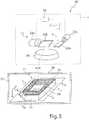
- Fig. 5 shows a processing machine 20, which also allows the production of a three-dimensional component 21 with a higher build-up rate.
- the processing machine 20 of Fig. 5 is different from the one in Fig. 4 Processing machine 20 shown essentially in that the irradiation device 1 has no beam shaping device.
- the laser beam 3 generated by the beam source 2 is thus irradiated without changing its beam profile and thus with a typically circular or circular beam cross section or "spot" with the aid of the scanner device 15 onto the processing field 11, more precisely onto the uppermost powder layer 25 ,
- Fig. 6a shows a section of the uppermost powder layer 25 with a portion T a of a layer of the generated three-dimensional component 21 of Fig. 5 and with the laser beam 3, more precisely with its point-shaped beam profile.
- the laser beam 3 is moved with an oscillating movement in a first direction R1 (X direction) continuously and repeatedly over the powder layer 25, wherein a line-shaped irradiation region 30 is generated, in which the powder layer 25 is melted.
- the line-shaped irradiation area 30, which in Fig. 6a is first generated at an upper end of the portion T a is in a second, different from the first direction R2 along a in Fig. 6a indicated trajectory 31 moves over the powder layer 25 until the portion T a completely melted with the desired geometry and thus the first portion T a of the layer of the three-dimensional component 21 is completely made.
- the second direction R2, ie the feed direction corresponds at the upper end of the powder layer 25 to the (negative) Y direction of the machining field 11 and is also continuously rotated by 90 ° during the movement of the linear irradiation region 30, so that the second direction R2 on the right End of the subarea T a with the X direction of the irradiation field 11 matches.
- Fig. 6a is also indicated, during the movement of the line-shaped irradiation region 30 via the powder layer 25, the two directions R1, R2 are not necessarily aligned perpendicular to each other, but the angle at which the two directions R1, R2 are aligned with each other in the processing field 11 at vary the movement over the powder layer 25.
- the power of the laser beam 3 is preferably controlled during the oscillating movement in such a way that the area to be illuminated or the subarea T a undergoes a constant, constant energy input.
- the power in the movement along the trajectory 31 is lowered in positive X and Y directions and increased in negative X and Y directions.
- the rotary drives 23a, 23b of the two scanner mirrors 22a, 22b are suitably controlled with the aid of the control device 16 in order to position the laser beam 3 in the processing field 11 of the scanner device 15 appropriately.
- the rotary actuators 23a, 23b can be driven to generate the oscillating movement with a high frequency in order to achieve an oscillation frequency of, for example, more than about 1 kHz.
- the laser beam 3 can be moved in particular in the processing field 11 in such a way that the line-shaped irradiation area 30 can be aligned or rotated practically as desired and also the (double) amplitude of the oscillating movement, i. the length L of the line-shaped irradiation area 30, can be varied over a comparatively large value range, which of course is limited by the size of the processing field 11 of the scanner device 15.
- the control device 16 accesses data on the (two-dimensional) geometry of the three-dimensional component 21 to be generated on the respective powder layer 25 to be irradiated, which are stored in a memory device or which are predetermined by a programming system.
- the two edges 32a, b of the produced portion T a which in the movement of the two ends of the line-shaped irradiation region 30 along the in Fig. 6a, b shown trajectory 31, a high smoothness, ie they correspond with a high resolution of the desired contour of the edge of the produced portion T a .
- the high resolution is achieved by changing the orientation as well as by changing the length L of the line-shaped irradiation area 30 during the movement along the path curve 31.
- One or possibly both edges 32a, b of the subregion T a may coincide with a contour of the component 21 to be produced.
- one or both edges 32 a, b of the subarea T a may not match the contour of the component 21, since laterally adjoining the respective edge 32 a, b may be another subregion of the component 21 to be produced followed.
- Fig. 6b shows how Fig. 6a the production of the portion T a of the layer of the three-dimensional component 21, wherein in Fig. 6b However, in contrast to Fig. 6a not one, but three laser beams 3a-c are used to generate the line-shaped irradiation area 30.
- Each of the three laser beams 3a-c carries out an oscillating movement which forms first, second and third sections 30a-c of the line-shaped irradiation area 30.
- the three sections 30a-c, the line-shaped irradiation area 30th form, directly adjacent to each other and have the same length L1 (corresponding to twice the amplitude of the oscillating motion) on.
- L1 corresponding to twice the amplitude of the oscillating motion
- the three laser beams 3a-c are independently movable over the powder layer 25 in the example shown.
- the scanner device 15 may comprise three pairs of scanner mirrors 22a, 22b each serving as two-dimensional scanners for moving a respective laser beam 3a-c over the powder layer 25. *** " It is understood that two or more than three laser beams 3a-c can be moved in this way independently of one another via the powder layer 25 or via the processing field 11.
- diffractive, optionally switchable optical elements can also be used to produce two or more laser beams 3a-c to move independently over the powder layer 25.
- two or more laser beams 3a-c can be moved independently of each other via the powder layer 25, they can be moved as in FIG Fig. 6b is shown on the one hand used for the joint production of a linear irradiation area 30.
- the two or more laser beams 3a-c on the other hand can also be used to independently different subregions T 1a ,..., T 1d, T 2 of the powder layer 25 (see FIG. Fig.
- the respective laser beam 3a-c does not perform an oscillating movement.
- the use of a plurality of laser beams 3a-c thus significantly increases the flexibility in the production of different three-dimensional components 21.
- Fig. 6b shown line-shaped irradiation area 30 can be generated in different ways by means of two or more laser beams 3a, 3b, to an influence on the stability of the melt in the sense of a Schmelzbadberuhist or an effect on the homogeneity of the melt to take, and possibly to increase the build-up rate by the length L of the line-shaped irradiation region 30 and the molten bath is increased.
- Fig. 7a FIG. 12 shows the generation of the line-shaped irradiation area 30 using two laser beams 3a, 3b which are analogous to FIG Fig. 6b produce a respective portion 30a, 30b of identical length L1, each performing an oscillating motion.
- FIG. 12 shows a case where the two portions 30a, 30b partially overlap in a range that is about 10% of the length L1.
- FIG. 7c FIG. 12 shows a case where the two portions 30a, 30b have different lengths L1, L2 to form the line-shaped irradiation area 30 in common. It is understood that the two sections 30a, 30b may possibly completely (100%) overlap, wherein in principle any value for the overlap (ie between 0% and 100%) is possible.
- Fig. 8a, b show the case of the linear irradiation area of Fig. 7a in which the two sections 30a, b do not overlap and have an identical length L1.
- the two sections 30a, b have a constant phase relationship, ie the oscillating movement of the respective laser beams 3a, 3b takes place with the same oscillation frequency.
- Fig. 8a shows the case in which the two laser beams 3a, 3b are moved in opposite directions
- Fig. 8b shows the case where the two laser beams 3a, 3b are moved in the same direction. It is understood that other phase relationships between the oscillating movements of the two laser beams 3a, 3b are possible.
- Fig. 9 finally shows the different directions of rotation of the oscillating movement of the two laser beams 3a, 3b in the opposite movement of Fig. 8a .
- the laser beams 3a, 3b as in Fig. 8a, b is oscillated along a common line and that only to illustrate the sense of rotation of the oscillating motion in Fig. 9 a meandering movement is shown.
- a fixed phase relationship between the oscillating movements of the two laser beams 3a, 3b does not necessarily have to exist, but that the oscillation frequencies of the two laser beams 3a, 3b are optionally chosen differently can be.
- the frequency of the oscillating movement of the at least one laser beam 3, 3a-c and thus the over a period averaged speed v1 in the first direction R1 (see. Fig. 6b ) used to generate the line-shaped irradiation area 30 is significantly larger than the feed speed v2, that is, the speed in the second direction R2.
- the speed v1 of the oscillating motion is at least ten times as large, preferably at least twenty times as large as the feed speed v2.
- the movement of the laser beam or beams 3, 3a-c for producing the three-dimensional component 21 or for producing a respective layer or partial region T a of a respective layer of the component 21 is controlled by the control device 16.
- the control device 16 can, as in Fig. 5 is shown to be disposed within the irradiation device 1, but it is also possible that it is arranged outside of the irradiation device 1 and communicates via a wireless or wired connection with the scanner device 15 and with other components of the irradiation device 1 and the processing machine 20.
Description
Die vorliegende Erfindung betrifft eine Bestrahlungseinrichtung für eine Bearbeitungsmaschine zum Herstellen von dreidimensionalen Bauteilen durch Bestrahlen von Pulverschichten mittels eines Hochenergiestrahls, insbesondere mittels eines Laserstrahles gemäß dem Oberbegriff des Anspruchs 1 (siehe
Dreidimensionale Bauteile können durch so genannte generative Fertigungsverfahren (auch als Additive-Manufacturing-Verfahren bezeichnet) hergestellt werden. Bei derartigen Verfahren wird das dreidimensionale Bauteil schichtweise bzw. lagenweise generiert. Beim so genannten selektiven Laserschmelzen (engl. "selective laser melting", auch: SLM) und beim so genannten selektiven Lasersintern (engl. "selective laser sintering", auch: SLS) wird zu diesem Zweck ein Pulverwerkstoff lokal durch einen Hochenergiestrahl, insbesondere einen Laserstrahl, aufgeschmolzen, um eine Lage des dreidimensionalen Bauteils zu erzeugen.Three-dimensional components can be produced by so-called additive manufacturing processes (also referred to as additive manufacturing processes). In such methods, the three-dimensional component is generated in layers or in layers. In the so-called selective laser melting (also: SLM) and in the so-called selective laser sintering (also known as "selective laser sintering", also: SLS), a powder material is locally produced by a high-energy beam, in particular a Laser beam, melted to create a position of the three-dimensional component.
Die
In der
Aus der
Aneinander angrenzende bzw. geringfügig seitlich überlappende Wege innerhalb der Kontur werden in der
Ein weiteres Problem stellt gemäß der
In der
In der
Der Erfindung liegt die Aufgabe zugrunde, eine Bestrahlungseinrichtung, eine Bearbeitungsmaschine mit einer solchen Bestrahlungseinrichtung sowie zugehörige Verfahren anzugeben, mit denen eine besonders effiziente Herstellung eines dreidimensionalen Bauteils möglich ist.The invention is based on the object, an irradiation device, a processing machine with such an irradiation device and associated Specify method, with which a particularly efficient production of a three-dimensional component is possible.
Eine Bestrahlungseinrichtung gemäß der Erfindung ist im Anspruch 1 definiert.An irradiation device according to the invention is defined in
Die Strahlformungseinrichtung ist ausgebildet, die Länge und die Breite des Strahlprofils zu verändern. Gemäß der Erfindung werden die beiden Abmessungen (Länge bzw. Breite) unabhängig voneinander (insbesondere kontinuierlich) verändert. Die Strahlformungseinrichtung kann ausgebildet sein, ein linienförmiges Strahlprofil zu erzeugen, d.h. ein Strahlprofil, dessen Länge deutlich größer ist als dessen Breite. Beispielsweise kann bei einem solchen linienförmigen Strahlprofil die Länge L mehr als zwanzig Mal, mehr als zehn Mal oder mehr als fünf Mal so groß sein wie die Breite B (L > 20 x B, L > 10 x B bzw. L > 5 x B).The beam shaping device is designed to change the length and the width of the beam profile. According to the invention, the two dimensions (length or width) are changed independently of one another (in particular continuously). The beam shaping device can be formed be to produce a line-shaped beam profile, ie a beam profile whose length is significantly greater than its width. For example, with such a linear beam profile, the length L may be more than twenty times, more than ten times, or more than five times the width B (L> 20 × B, L> 10 × B or L × 5 × B, respectively) ).
Die Scannereinrichtung ist typischer Weise im Strahlweg des Hochenergiestrahls nach der Strahlformungseinrichtung angeordnet und dient dazu, den Hochenergiestrahl auf eine (einstellbare) Position in einem Bearbeitungsfeld der Scannereinrichtung auszurichten. Im Folgenden wird unter dem Bearbeitungsfeld ein zweidimensionaler Bereich (auch: Scanbereich) verstanden, in das der Hochenergiestrahl mittels einer Fokussiereinrichtung fokussiert wird. Der Hochenergiestrahl kann mittels der Scannereinrichtung auf jede beliebige Position innerhalb des Bearbeitungsfeldes ausgerichtet werden. Die Fokussiereinrichtung zur Fokussierung des Hochenergiestrahls in das Bearbeitungsfeld kann vor oder nach der Scannereinrichtung angeordnet sein. Das Bearbeitungsfeld kann insbesondere in einer Ebene verlaufen, in der eine Pulverschicht angeordnet ist, die mittels des Hochenergiestrahls bestrahlt werden soll. Idealer Weise bildet das Bearbeitungsfeld eine ebene Fläche, in der die zu bestrahlende Pulverschicht angeordnet ist. Gegebenenfalls kann das Bearbeitungsfeld insbesondere an seinen seitlichen Rändern geringfügig von einer planen Geometrie abweichen.The scanner device is typically located in the beam path of the high energy beam after the beamformer and serves to direct the high energy beam to an (adjustable) position in an edit field of the scanner device. In the following, the machining field is understood to mean a two-dimensional region (also: scanning region) in which the high-energy beam is focused by means of a focusing device. The high energy beam can be aligned by the scanner device to any position within the edit field. The focusing device for focusing the high-energy beam into the processing field can be arranged before or after the scanner device. The processing field can in particular run in a plane in which a powder layer is to be irradiated by means of the high-energy beam. Ideally, the processing field forms a flat surface in which the powder layer to be irradiated is arranged. Optionally, the processing field may differ slightly from a planar geometry, especially at its lateral edges.
Bei herkömmlichen Bestrahlungseinrichtungen wird das Bearbeitungsfeld oder - bei der Anwendung des Hülle-Kern-Verfahrens - einer oder mehrere Teilbereiche des Bearbeitungsfeldes mit Hilfe einer Scannereinrichtung mäanderförmig entlang von mehreren Linien abgefahren, an deren Enden es jeweils zu einer Richtungsumkehr bei dem Scanprozess kommt. Die Richtungsumkehr erzeugt eine Verzögerung und erneute Beschleunigung von in der Scannereinrichtung vorgesehenen beweglichen Bauteilen, beispielsweise in Form von Scannerspiegeln, was zu Zeitverlusten beim Scanprozess führt und einen limitierenden Faktor für die Aufbaurate bei der Herstellung von dreidimensionalen Bauteilen darstellt.In conventional irradiation devices, the processing field or, in the case of the shell-core method, one or more subareas of the processing field are meandered along a plurality of lines by means of a scanner device, at the ends of which a direction reversal occurs during the scanning process. The reversal of direction produces a delay and re-acceleration of moveable components provided in the scanner device, for example in the form of scanner mirrors, which leads to time losses in the scanning process and represents a limiting factor for the build-up rate in the production of three-dimensional components.
Durch die Möglichkeit, das Strahlprofil des Hochenergiestrahls in Abhängigkeit von der Position des Hochenergiestrahls auf dem Bearbeitungsfeld zu verändern, kann die Fokusgeometrie des Hochenergiestrahls auf dem Bearbeitungsfeld an die Geometrie des herzustellenden dreidimensionalen Bauteils angepasst werden, ohne dass zu diesem Zweck zwei oder mehr optische Abbildungssysteme bzw. Laser erforderlich sind. Beispielsweise kann die Länge des Strahlprofils senkrecht zur momentanen Scanrichtung auf dem Bearbeitungsfeld an die Größe, beispielsweise an die Breite eines jeweils zu bestrahlenden flächenhaften Teilbereichs des Bearbeitungsfeldes angepasst werden. In diesem Fall ist es ggf. ausreichend, wenn der Hochenergiestrahl den zu bestrahlenden Teilbereich des Bearbeitungsfelds nur ein einziges Mal entlang einer vorgegebenen Bahnkurve abfährt, die von der Scannereinrichtung vorgegeben wird. Insbesondere kann die zu bestrahlende Fläche der jeweiligen Pulverschicht von einem Programmiersystem in Abhängigkeit von der Geometrie des herzustellenden Bauteils in mehrere streifenförmige Teilbereiche aufgeteilt werden, deren Streifenbreite typischer Weise nicht größer ist als die maximale Länge des Strahlprofils des Hochenergiestrahls in dem Bearbeitungsfeld. Ein jeweiliger streifenförmiger Teilbereich kann mittels des Hochenergiestrahls mit angepasster Länge (und ggf. angepasster Breite) des Strahlprofils ein einziges Mal entlang einer typischer Weise nicht mäanderförmigen Bahnkurve abgefahren werden, so dass auf ein mäanderförmiges Abrastern der zu bestrahlenden flächenhaften Teilbereiche des Bearbeitungsfeldes verzichtet werden kann. Die Scannereinrichtung dient somit nur noch zur Vorgabe der Bahnkurve, entlang derer der in seiner Geometrie bzw. in seinen Abmessungen veränderbare Hochenergiestrahl über das Bearbeitungsfeld bewegt wird, wobei die Bahnkurve typischer Weise dem Weg des Zentrums des in seiner Geometrie veränderlichen Strahlprofils des Hochenergiestrahls entspricht. Da keine schnelle Richtungsumkehr an den Rändern der mäanderförmigen Linien mehr erforderlich ist, kann für die Bestrahlung des Bauteils bzw. der Pulverschicht eine kostengünstige Scannereinrichtung verwendet werden, die weniger dynamisch arbeitet als dies bei herkömmlichen Bestrahlungseinrichtungen zum Herstellen von dreidimensionalen Bauteilen der Fall ist.The ability to change the beam profile of the high energy beam depending on the position of the high energy beam on the edit field, can the focus geometry of the high energy beam can be adapted to the geometry of the manufactured three-dimensional component on the machining field, without the need for two or more optical imaging systems or laser for this purpose. For example, the length of the beam profile perpendicular to the current scanning direction on the machining field can be adapted to the size, for example, to the width of a respective planar partial region of the machining field to be irradiated. In this case, it may be sufficient if the high-energy beam leaves the partial area of the processing field to be irradiated only once along a predetermined trajectory which is predetermined by the scanner device. In particular, the surface to be irradiated of the respective powder layer can be divided by a programming system depending on the geometry of the component to be produced in a plurality of strip-shaped portions whose strip width is typically not greater than the maximum length of the beam profile of the high energy beam in the edit field. A respective strip-shaped subarea can be traversed by means of the high-energy beam of adapted length (and possibly adapted width) of the beam profile for a single time along a typical non-meandering trajectory, so that it is possible to dispense with a meandering scanning of the planar subregions of the processing field to be irradiated. The scanner device thus serves only to specify the trajectory along which the variable in its geometry or in its dimensions variable high-energy beam is moved over the processing field, the trajectory typically corresponds to the path of the center of variable in its geometry beam profile of the high energy beam. Since no rapid reversal of the direction at the edges of the meandering lines is required any more, a low-cost scanner device which operates less dynamically than is the case with conventional irradiation devices for producing three-dimensional components can be used for the irradiation of the component or the powder layer.
Gemäß der Erfindung weist die Strahlformungseinrichtung mindestens ein erstes einstellbares Strahlteleskop zur Veränderung der Länge des Strahlprofils auf. Durch die Veränderung der Länge des Strahlprofils kann beispielsweise die Abmessung des Laserstrahlfokus auf dem Bearbeitungsfeld in einer Richtung quer zu einer (momentanen) Scanrichtung, entlang derer der Laserstrahl mittels der Scannereinrichtung bewegt wird, verändert und an die Geometrie eines zu bestrahlenden Teilbereichs des Bestrahlungsfeldes angepasst werden. Das Strahlteleskop kann beispielsweise zwei oder mehr Zylinderlinsen aufweisen.According to the invention, the beam shaping device has at least one first adjustable beam telescope for changing the length of the beam profile. By changing the length of the beam profile, for example, the dimension of the laser beam focus on the processing field in a direction transverse to a (current) scanning direction, along which the laser beam is moved by means of the scanner device, changed and adapted to the geometry of a part of the irradiation field to be irradiated. The beam telescope may for example have two or more cylindrical lenses.
Gemäß der Erfindung weist die Strahlformungseinrichtung mindestens ein zweites einstellbares Strahlteleskop zur Veränderung der Breite des Strahlprofils, unabhängig von der Einstellung der Länge des Strahlprofils, auf. Zu diesem Zweck kann das zweite Strahlteleskop ebenfalls zwei oder mehr Zylinderlinsen aufweisen, deren Zylinderachse typischer Weise senkrecht zur Zylinderachse der Zylinderlinsen des ersten Strahlteleskops ausgerichtet sind. Die (ggf. zusätzliche) Veränderung der Breite des Strahlprofils kann beispielsweise günstig sein, um eine Vor- und/oder Nacherwärmung eines jeweils bestrahlten Teilbereichs der Pulverschicht zu erzeugen, wenn die Längsrichtung des Hochenergiestrahls quer zur momentanen Scanrichtung entlang der Bahn- bzw. Scankurve ausgerichtet ist.According to the invention, the beam shaping device has at least one second adjustable beam telescope for changing the width of the beam profile, irrespective of the setting of the length of the beam profile. For this purpose, the second beam telescope may likewise have two or more cylindrical lenses whose cylinder axis is typically aligned perpendicular to the cylinder axis of the cylindrical lenses of the first beam telescope. The (possibly additional) change in the width of the beam profile can be favorable, for example, to produce a preheating and / or reheating of each irradiated portion of the powder layer, when the longitudinal direction of the high energy beam aligned transversely to the instantaneous scanning direction along the path or scan curve is.
Bei einer Weiterbildung weist/weisen mindestens ein erstes Strahlteleskop und/oder mindestens ein zweites Strahlteleskop eine in Richtung der Strahlachse des Hochenergiestrahls verschiebbare Linse, bevorzugt eine Zylinderlinse, auf. In der Regel weist ein jeweiliges Strahlteleskop typischer Weise mindestens eine, in der Regel mindestens zwei Zylinderlinsen auf, um das Strahlprofil in einer Richtung (und unabhängig von einer zweiten, zur ersten senkrechten Richtung) einstellen zu können. Mindestens eine der Zylinderlinsen kann in Strahlrichtung des Hochenergiestrahls verschiebbar ausgebildet sein, um die Länge oder die Breite des Strahlprofils zu verändern. Die Verschiebung der (Zylinder-)Linse kann mit Hilfe eines Aktors der Strahlformungseinrichtung in Abhängigkeit von der einzustellenden Länge bzw. Breite des Strahlprofils erfolgen. An Stelle von Zylinderlinsen können ggf. andere optische Komponenten in dem bzw. in den Strahlteleskop(en) verwendet werden, welche die gleiche oder eine ähnliche optische Wirkung aufweisen, beispielsweise reflektierende optische Elemente.In a development, at least one first beam telescope and / or at least one second beam telescope have / have a lens displaceable in the direction of the beam axis of the high-energy beam, preferably a cylindrical lens. As a rule, a respective beam telescope typically has at least one, as a rule at least two cylindrical lenses in order to be able to set the beam profile in one direction (and independently of a second direction perpendicular to the first). At least one of the cylindrical lenses may be designed to be displaceable in the beam direction of the high-energy beam in order to change the length or the width of the beam profile. The displacement of the (cylindrical) lens can take place with the aid of an actuator of the beam shaping device as a function of the length or width of the beam profile to be set. Instead of cylindrical lenses, other optical components may optionally be used in or in the beam telescope (s) which have the same or a similar optical effect, for example reflective optical elements.
In einer weiteren Ausführungsform ist die Strahlformungseinrichtung zur Formung eines Strahlprofils des Hochenergiestrahls ausgebildet, dessen Länge mit dessen Breite übereinstimmt. Die Strahlformungseinrichtung ist in diesem Fall nicht nur ausgebildet, ein asymmetrisches Strahlprofil (Länge > Breite) zu erzeugen, sondern diese kann auch dazu dienen, ein symmetrisches Strahlprofil mit (im Wesentlichen) identischen Abmessungen in der ersten und in der zweiten Richtung zu erzeugen, wobei die Abmessungen in beiden Richtungen in diesem Fall typischer Weise sehr gering sind, so dass ein (annähernd) punktförmiges Strahlprofil erzeugt wird. Mittels eines Hochenergiestrahls mit einem solchen annähernd punktförmigen Strahlprofil können beispielsweise Konturen bzw. Konturlinien des herzustellenden dreidimensionalen Bauteils nachgefahren werden. Alternativ ist es möglich, zum Nachfahren der Konturlinien die Strahlformungseinrichtung, insbesondere das bzw. die Strahlteleskope, aus dem Strahlengang des Hochenergiestrahls zu entfernen. Auf diese Weise bleibt das typischer Weise symmetrische Strahlprofil, das von einer Laserquelle erzeugt wird und das bei geeigneter Auslegung ggf. auch an der Austrittsfläche einer Lichtleitfaser vorliegt, beim Durchtritt durch die Bestrahlungseinrichtung erhalten. Wird die Strahlformungseinrichtung aus dem Strahlengang des Hochenergiestrahls entfernt, ist es ggf. erforderlich, an Stelle der Strahlformungseinrichtung eine zusätzliche Fokussieroptik im Strahlengang anzuordnen.In a further embodiment, the beam shaping device is designed to form a beam profile of the high-energy beam whose length coincides with the beam path Width matches. In this case, the beam-shaping device is not only designed to produce an asymmetrical beam profile (length> width), but it can also serve to produce a symmetrical beam profile with (substantially) identical dimensions in the first and in the second direction the dimensions in both directions are typically very small in this case, so that an (approximately) point-shaped beam profile is produced. For example, contours or contour lines of the three-dimensional component to be produced can be traced by means of a high-energy beam with such an approximately point-shaped beam profile. Alternatively, it is possible to remove the beam shaping device, in particular the or the beam telescopes, from the beam path of the high-energy beam for tracing the contour lines. In this way, the symmetrical beam profile, which is generated by a laser source and which, with a suitable design, may also be present at the exit surface of an optical fiber, typically remains in the passage through the irradiation device. If the beam-shaping device is removed from the beam path of the high-energy beam, it may be necessary to arrange an additional focusing optical system in the beam path instead of the beam-shaping device.
Bei einer Ausführungsform ist die Strahlformungseinrichtung ausgebildet, die Ausrichtung der ersten Richtung und der zweiten Richtung des Strahlprofils in einer Ebene senkrecht zur Strahlachse des Hochenergiestrahls in Abhängigkeit von der Position des Hochenergiestrahls in dem Bearbeitungsfeld zu verändern, insbesondere die erste und die zweite Richtung in der Ebene senkrecht zur Strahlachse des Hochenergiestrahls zu drehen. Durch die Drehung des (asymmetrischen) Strahlprofils in der Ebene senkrecht zur Strahlachse des Hochenergiestrahls kann die Ausrichtung des (fokussierten) Strahlprofils in dem Bearbeitungsfeld, welches durch die Scannereinrichtung definiert wird, verändert werden. Insbesondere kann das (asymmetrische) Strahlprofil des Laserstrahls in dem Bearbeitungsfeld gedreht werden, um erforderlichenfalls das Nachfahren von bestimmten Konturen des zu erzeugenden Bauteils zu erleichtern. Auch können falls dies gewünscht ist die erste und die zweite Richtung des Strahlprofils in Abhängigkeit von der momentanen Scanrichtung auf dem Bearbeitungsfeldes beispielsweise so gedreht werden, dass die Längsrichtung des Strahlprofils stets senkrecht zur Bahnkurve des Hochenergiestrahls entlang des Bearbeitungsfelds verläuft. Eine Drehung des Strahlprofils ist beispielsweise günstig, wenn Teilbereiche des Bearbeitungsfeldes mittels des Hochenergiestrahls bestrahlt werden sollen, die eine unterschiedliche Orientierung in dem Bearbeitungsfeld aufweisen, so dass diese typischer Weise entlang von Bahnkurven abgefahren werden, die ebenfalls unterschiedlich orientiert sind. Es versteht sich, dass ggf. simultan zur Drehung des Strahlprofils auch die Länge und/oder die Breite des Strahlprofils verändert werden kann/können, um eine gewünschte flächige Bestrahlung des Bearbeitungsfeldes bzw. eines jeweiligen Teilbereichs des Bearbeitungsfeldes zu erreichen.In one embodiment, the beam shaping device is configured to change the orientation of the first direction and the second direction of the beam profile in a plane perpendicular to the beam axis of the high energy beam depending on the position of the high energy beam in the processing field, in particular the first and the second direction in the plane to rotate perpendicular to the beam axis of the high energy beam. By rotating the (asymmetric) beam profile in the plane perpendicular to the beam axis of the high energy beam, the orientation of the (focused) beam profile in the edit field defined by the scanner device can be changed. In particular, the (asymmetric) beam profile of the laser beam in the processing field can be rotated in order to facilitate, if necessary, the tracing of certain contours of the component to be produced. If desired, the first and the second direction of the beam profile can also be rotated, for example, depending on the instantaneous scanning direction on the machining field such that the longitudinal direction of the beam profile is always perpendicular to the beam profile Trajectory of the high energy beam along the processing field runs. A rotation of the beam profile is favorable, for example, if partial regions of the processing field are to be irradiated by means of the high-energy beam, which have a different orientation in the processing field, so that they are typically traversed along trajectories which are likewise oriented differently. It goes without saying that, if necessary, the length and / or the width of the beam profile can also be changed simultaneously to the rotation of the beam profile in order to achieve a desired planar irradiation of the processing field or of a respective subarea of the processing field.
Bei einer Weiterbildung ist/sind das mindestens eine erste Strahlteleskop und/oder das mindestens eine zweite Strahlteleskop um die Strahlachse des Hochenergiestrahls drehbar gelagert und die Bestrahlungseinrichtung weist mindestens einen Antrieb zur Drehung des mindestens einen ersten und/oder zweiten Strahlteleskops um die Strahlachse auf. Durch die Drehung des jeweiligen Strahlteleskops um die Strahlachse des Hochenergiestrahls kann die Ausrichtung des (asymmetrischen) Strahlprofils auf besonders einfache Weise verändert werden.In a development, the at least one first beam telescope and / or the at least one second beam telescope are / is rotatably mounted about the beam axis of the high-energy beam and the irradiation device has at least one drive for rotating the at least one first and / or second beam telescope about the beam axis. By rotating the respective beam telescope around the beam axis of the high-energy beam, the alignment of the (asymmetrical) beam profile can be changed in a particularly simple manner.
Bei einer weiteren Ausführungsform umfasst die Bestrahlungseinrichtung zusätzlich eine im Strahlweg des Hochenergiestrahls vor dem mindestens einen ersten und/oder zweiten Strahlteleskop angeordnete Kollimationseinrichtung zur Kollimation des Hochenergiestrahls. Die Kollimationseinrichtung kann eine insbesondere rotationssymmetrische Linse, beispielsweise eine Bikonvexlinse oder eine Plankonvexlinse, aufweisen, um den typischer Weise divergent auftreffenden Hochenergiestrahl zu kollimieren. Der Hochenergiestrahl kann beispielsweise divergent aus einem Faserende einer Faser austreten, in dem der Hochenergiestrahl, beispielsweise in Form eines Laserstrahls, geführt ist. Die Faser kann einen runden bzw. zylindrischen Querschnitt aufweisen, so dass der Hochenergiestrahl mit einem runden Strahlquerschnitt aus der Faser austritt, es ist aber auch möglich, dass die Faser einen z.B. rechteckigen Querschnitt aufweist, so dass der Hochenergiestrahl mit einem rechteckigen Strahlprofil aus der Faser austritt. Mit Hilfe des bzw. der Strahlteleskope kann die Länge und die Breite des Strahlprofils des Hochenergiestrahls verändert werden, beispielsweise kann aus einem runden Strahlquerschnitt nach der Kollimationseinrichtung ein elliptischer Strahlquerschnitt erzeugt werden, oder es kann das Aspektverhältnis (Länge : Breite) des rechteckigen Strahlprofils verändert werden.In a further embodiment, the irradiation device additionally comprises a collimation device arranged in the beam path of the high-energy beam in front of the at least one first and / or second beam telescope for collimation of the high-energy beam. The collimation device can have a particularly rotationally symmetrical lens, for example a biconvex lens or a plano-convex lens, in order to collimate the typically high-energy beam divergently incident. The high-energy beam can, for example, divergent from a fiber end of a fiber, in which the high-energy beam, for example in the form of a laser beam, is guided. The fiber may have a round or cylindrical cross-section so that the high-energy beam emerges from the fiber with a circular beam cross-section, but it is also possible for the fiber to have a rectangular cross-section, for example, so that the high-energy beam has a rectangular beam profile from the fiber exit. With the help of the or the beam telescopes, the length and the width of the beam profile of the high-energy beam can be changed, for example, from a round beam cross-section after the collimation an elliptical Beam cross section are generated, or it can the aspect ratio (length: width) of the rectangular beam profile can be changed.
Bei einer weiteren Ausführungsform weist die Strahlformungseinrichtung zur zusätzlichen Formung, insbesondere zur Aufteilung, des Strahlprofils mindestens ein weiteres optisches Element auf. Bei dem weiteren optischen Element für die zusätzliche Formung des Strahlprofils kann es sich beispielsweise um ein diffraktives optisches Element handeln. Das diffraktive optische Element kann beispielsweise in Form eines Beugungsgitters ausgebildet sein, es ist aber auch möglich, das diffraktive optische Element z.B. in der Art eines computergenerierten Hologramms oder dergleichen auszubilden. Ein diffraktives optisches Element ermöglicht es, aus dem Strahlprofil des auf dieses auftreffenden Hochenergiestrahls ein Strahlprofil mit einer grundsätzlich annähernd beliebigen Geometrie zu erzeugen. Beispielsweise kann das diffraktive optische Element dazu dienen, ein Strahlprofil mit einer rechteckigen Geometrie in ein Strahlprofil mit einer elliptischen Geometrie umzuwandeln, oder umgekehrt.In a further embodiment, the beam-shaping device has at least one further optical element for additional shaping, in particular for division, of the beam profile. The further optical element for the additional shaping of the beam profile may, for example, be a diffractive optical element. The diffractive optical element may, for example, be in the form of a diffraction grating, but it is also possible to use the diffractive optical element, e.g. in the manner of a computer-generated hologram or the like. A diffractive optical element makes it possible to generate from the beam profile of the high-energy beam incident thereon a beam profile with a fundamentally approximately arbitrary geometry. For example, the diffractive optical element may serve to convert a beam profile having a rectangular geometry into a beam profile having an elliptical geometry, or vice versa.
Bei dem weiteren optischen Element kann es sich um ein zusätzliches optisches Element der Strahlformungseinrichtung handeln. In diesem Fall kann das weitere optische Element ggf. in den Strahlengang des Hochenergiestrahls eingebracht oder aus diesem entfernt werden, je nachdem, ob die optische Wirkung des weiteren optischen Elements bei der Herstellung eines jeweiligen dreidimensionalen Bauteils bzw. einer oder mehrerer Schichten oder Teilbereichen von Schichten des dreidimensionalen Bauteils gewünscht ist oder nicht. Es ist auch möglich, dass ein optisches Element, z.B. eine Linse, welches ohnehin in der Strahlformungseinrichtung angeordnet ist, als weiteres, z.B. diffraktives optisches Element wirkt, beispielsweise die weiter oben beschriebene Kollimationslinse oder ein optisches Element, insbesondere eine Linse, des ersten und/oder des zweiten Strahlteleskops.The further optical element may be an additional optical element of the beam shaping device. In this case, the further optical element may possibly be introduced into or removed from the beam path of the high-energy beam, depending on whether the optical effect of the further optical element in the production of a respective three-dimensional component or one or more layers or subregions of layers the three-dimensional component is desired or not. It is also possible that an optical element, e.g. a lens, which is arranged anyway in the beam-shaping device, as another, e.g. diffractive optical element acts, for example, the collimating lens described above or an optical element, in particular a lens, the first and / or the second beam telescope.
Alternativ oder zusätzlich zur Verwendung eines diffraktiven optischen Elements ist es möglich, eines oder mehrere weitere optische Elemente für die zusätzliche Strahlformung zu verwenden, welche(s) nur auf einzelne Profilbereiche des Strahlprofils optisch einwirkt/einwirken, beispielsweise um diese relativ zum restlichen Strahlprofil zu separieren, insbesondere lateral zu versetzen. Beispielsweise kann bzw. können mittels eines oder mehrerer keilförmiger optischer Elemente, die nur einen Teil des Strahlengangs überdecken, einer oder mehrere Profilbereiche des Strahlprofils von anderen Profilbereichen des Strahlprofils räumlich separiert werden, so dass das Strahlprofil in mehrere Profilbereiche aufgeteilt wird. Auf diese Weise kann ein Strahlprofil des Hochenergiestrahls erzeugt werden, welches z.B. entlang der zweiten Richtung, d.h. in seiner Breite, zwei- oder mehrgeteilt, beispielsweise dreigeteilt ist, d.h. ein Strahlprofil, das beispielsweise einen ersten Profilbereich, einen zweiten Profilbereich und einen dritten Profilbereich in der zweiten Richtung aufweist, die durch dazwischen liegende Profilbereiche getrennt sind, in denen das Strahlprofil nur eine sehr geringe Leistung aufweist. Eine solche Unterteilung des Strahlprofils insbesondere in der zweiten Richtung kann beispielsweise dazu dienen, eine Vorwärmung bzw. eine Nachwärmung des herzustellenden Bauteils bzw. der Pulverschicht zu erzeugen. In diesem Fall kann ggf. ein hoher Anteil, z.B. mehr als 70 %, der gesamten Leistung des Hochenergiestrahls auf den zweiten, mittleren Profilbereich entfallen. Sofern die Fläche des Teilbereichs des Strahlengangs, den das bzw. die weiteren optischen Element(e) überdecken, einstellbar ist, ist auch die Leistung des Hochenergiestrahls, die auf den ersten, zweiten sowie den dritten Profilbereich entfällt, jeweils einstellbar, um einen gewünschten Energieeintrag bei der Vorwärmung bzw. der Nachwärmung zu erhalten.As an alternative or in addition to the use of a diffractive optical element, it is possible to use one or more further optical elements for the additional beam shaping, which optically acts only on individual profile areas of the beam profile, for example around these relative to to separate remaining beam profile, in particular laterally offset. For example, by means of one or more wedge-shaped optical elements which cover only a part of the beam path, one or more profile regions of the beam profile can be spatially separated from other profile regions of the beam profile, so that the beam profile is divided into a plurality of profile regions. In this way, a beam profile of the high energy beam can be generated, for example along the second direction, ie in its width, two or more divided, for example, three-part, ie a beam profile, for example, a first profile area, a second profile area and a third profile area in the second direction, which are separated by intermediate profile regions in which the beam profile has only a very low power. Such a subdivision of the beam profile, in particular in the second direction, can serve, for example, to produce a preheating or a reheating of the component or the powder layer to be produced. In this case, if necessary, a high proportion, for example more than 70%, of the total power of the high-energy beam can be attributed to the second, medium profile range. If the area of the partial area of the beam path which the further optical element (s) overlap is adjustable, the power of the high energy beam, which is allocated to the first, second and third profile area, can also be set to a desired energy input to get in the preheating or reheating.
Bei einer weiteren Ausführungsform umfasst die Bestrahlungseinrichtung zusätzlich ein Objektiv, beispielsweise ein F/Theta-Objektiv, zur Fokussierung des Hochenergiestrahls bei der Ausrichtung auf die (jeweilige) Position in dem Bearbeitungsfeld der Scannereinrichtung. Ein solches Objektiv ist typischer Weise nach den in der Regel zwei beweglichen Scannerspiegeln der Scannereinrichtung angeordnet, welche dazu dienen, den Hochenergiestrahl auf eine beliebige Position in dem Bearbeitungsfeld auszurichten. Ein Objektiv ermöglicht es, den Hochenergiestrahl in einem (annähernd) ebenen Bearbeitungsfeld zu fokussieren, an dem typischer Weise die jeweils zu bestrahlende Pulverschicht angeordnet ist. Alternativ oder zusätzlich zur Fokussierung des Hochenergiestrahls nach der Scannereinrichtung z.B. mittels eines Objektivs ist es auch möglich, den Hochenergiestrahl mittels einer Fokussiereinrichtung, beispielsweise mittels einer oder mehrerer Linsen, zu fokussieren, die im Strahlweg vor der Scannereinrichtung angeordnet ist. In diesem Fall richtet die Scannereinrichtung an Stelle eines kollimierten Hochenergiestrahls einen konvergenten Hochenergiestrahl an eine jeweilige Position auf dem Bearbeitungsfeld aus.In a further embodiment, the irradiation device additionally comprises an objective, for example a F / theta objective, for focusing the high-energy beam in alignment with the (respective) position in the processing field of the scanner device. Such an objective is typically arranged after the typically two moving scanner mirrors of the scanner device, which serve to direct the high energy beam to any position in the processing field. A lens makes it possible to focus the high-energy beam in an (approximately) plane processing field, at which the respective powder layer to be irradiated is typically arranged. Alternatively or additionally to the focusing of the high-energy beam after the scanner device, for example by means of a lens, it is also possible to use the high-energy beam by means of a focusing device, for example by means of a or a plurality of lenses, which is arranged in the beam path in front of the scanner device. In this case, instead of a collimated high energy beam, the scanner device directs a convergent high energy beam to a respective position on the edit field.
Bei einer weiteren Ausführungsform weist die Bestrahlungseinrichtung eine Strahlquelle, insbesondere eine Laserquelle, zur Erzeugung des Hochenergiestrahls auf. Die Strahlquelle kann beispielsweise als CO2-Laser, als Nd:YAG-Laser, als Faser-Laser oder als Hochleistungsdioden-Laser ausgebildet sein, der idealer Weise einen Laserstrahl mit einer Leistung von mehr als 50 W, ggf. von mehreren kW erzeugt. Zur Führung des Laserstrahls von der Strahlquelle zur Strahlformungseinrichtung kann beispielsweise eine Lichtleitfaser dienen. An Stelle einer Laserquelle können auch andere Strahlquellen zur Erzeugung elektromagnetischer Strahlung bzw. eines Hochenergiestrahls verwendet werden, der eine Leistung von typischer Weise mindestens 50 W aufweist. Die momentane Leistung, die von der Strahlquelle abgegeben wird, kann ebenfalls in Abhängigkeit von der Position des Hochenergiestrahls in dem Bearbeitungsfeld und somit in Abhängigkeit von der momentanen Länge und/oder Breite des Strahlprofils verändert bzw. angepasst werden, beispielsweise mit Hilfe einer weiter unten näher beschriebenen Steuerungseinrichtung. Hierbei kann die Flächenleistung, welche von der momentanen Laserleistung und der momentanen Länge und Breite des Strahlprofils abhängt, mit der Vorschubgeschwindigkeit gekoppelt werden, um die Volumenaufschmelzleistung konstant bzw. stabil zu halten und auf diese Weise einen sicheren Aufschmelzprozess bzw. einen sicheren Schweißprozess zu gewährleisten.In a further embodiment, the irradiation device has a beam source, in particular a laser source, for generating the high-energy beam. The beam source can be designed, for example, as a CO 2 laser, as a Nd: YAG laser, as a fiber laser or as a high-power diode laser, which ideally generates a laser beam with a power of more than 50 W, possibly of several kW. For guiding the laser beam from the beam source to the beam shaping device, for example, an optical fiber can be used. Instead of a laser source, other beam sources for generating electromagnetic radiation or a high energy beam can be used, which has a power of typically at least 50 W. The instantaneous power output by the beam source may also be changed depending on the position of the high energy beam in the processing field and thus depending on the instantaneous length and / or width of the beam profile, for example, with the aid of one below described control device. In this case, the area performance, which depends on the instantaneous laser power and the instantaneous length and width of the beam profile, can be coupled to the feed rate in order to keep the volume melting performance constant and thus to ensure a safe reflow process or a reliable welding process.
Bei einer weiteren Ausführungsform weist die Bestrahlungseinrichtung eine Steuerungseinrichtung auf, welche ausgebildet bzw. programmiert ist, die Strahlformungseinrichtung zur Steuerung der Länge und/oder der Breite des Strahlprofils und bevorzugt der Ausrichtung der ersten Richtung und der zweiten Richtung des Strahlprofils (relativ zum Bearbeitungsfeld) in Abhängigkeit von der Position des Hochenergiestrahls in dem Bearbeitungsfeld anzusteuern. Mit Hilfe der Steuerungseinrichtung kann das Strahlprofil des Hochenergiestrahls in Abhängigkeit von der Position des Hochenergiestrahls in dem Bearbeitungsfeld dynamisch eingestellt bzw. gesteuert werden. Die Steuerungseinrichtung greift zu diesem Zweck auf Daten über die (zweidimensionale) Geometrie des zu erzeugenden dreidimensionalen Bauteils an der jeweils zu bestrahlenden Pulverschicht zurück, die in einer Speichereinrichtung abgelegt sind bzw. die von einem Programmiersystem vorgegeben werden. Die Steuerungseinrichtung kann insbesondere das Bearbeitungsfeld in mehrere Teilbereiche unterteilen, die nacheinander mit dem Hochenergiestrahl bestrahlt werden.In a further embodiment, the irradiation device has a control device which is designed or programmed, the beam shaping device for controlling the length and / or the width of the beam profile and preferably the orientation of the first direction and the second direction of the beam profile (relative to the processing field) Dependence on the position of the high-energy beam in the edit field to control. With the aid of the control device, the beam profile of the high-energy beam can be dynamically adjusted as a function of the position of the high-energy beam in the processing field be set or controlled. For this purpose, the control device uses data on the (two-dimensional) geometry of the three-dimensional component to be generated at the respective powder layer to be irradiated, which are stored in a memory device or which are predetermined by a programming system. In particular, the control device can subdivide the processing field into a plurality of partial regions which are irradiated in succession with the high-energy beam.
Wird der Hochenergiestrahl, genauer gesagt dessen Zentrum, beispielsweise entlang eines Teilbereichs einer zu bestrahlenden Pulverschicht bewegt, wobei die zweite Richtung (d.h. die Breite) des Strahlprofils in Längsrichtung des Teilbereichs verläuft, kann an einer jeweiligen Position des Bearbeitungsfeldes die Länge des Strahlprofils so angepasst werden, dass diese der Breite des Teilbereichs an der jeweiligen Position entspricht. Auf diese Weise kann ein solcher Teilbereich vollständig bestrahlt werden, obwohl der Hochenergiestrahl lediglich ein einziges Mal in Längsrichtung über den Teilbereich geführt wird. Insbesondere wenn in einem jeweiligen Teilbereich ein Flächenbereich vorhanden ist, der nicht bestrahlt werden soll, kann es vorteilhaft sein, die Breite und/oder die Ausrichtung des Hochenergiestrahls zu verändern.If the high-energy beam, more precisely its center, for example, moved along a portion of a powder layer to be irradiated, wherein the second direction (ie the width) of the beam profile in the longitudinal direction of the portion extends, the length of the beam profile can be adjusted at a respective position of the processing field in that it corresponds to the width of the partial area at the respective position. In this way, such a partial area can be completely irradiated, although the high-energy beam is guided only once in the longitudinal direction over the partial area. In particular, if there is a surface area in a respective subarea which is not to be irradiated, it may be advantageous to change the width and / or the orientation of the high energy beam.
Bei einer Weiterbildung ist die Steuerungseinrichtung ausgebildet, die Strahlformungseinrichtung anzusteuern, mindestens einen ersten zur Herstellung einer Schicht des dreidimensionalen Bauteils mittels des Hochenergiestrahls zu bestrahlenden ersten Teilbereich des Bearbeitungsfeldes mit einem Strahlprofil zu bestrahlen, dessen Länge größer ist als dessen Breite, und mindestens einen zweiten zur Herstellung derselben Schicht des dreidimensionalen Bauteils mittels des Hochenergiestrahls zu bestrahlenden zweiten Teilbereich des Bearbeitungsfelds mit einem Strahlprofil zu bestrahlen, dessen Länge und Breite (ungefähr) übereinstimmen. Wie weiter oben beschrieben wurde, ist die Steuerungseinrichtung ausgebildet, anhand der Geometrie des herzustellenden dreidimensionalen Bauteils zu bestrahlende Teilbereiche des Bearbeitungsfeldes (und damit der entsprechenden Pulverschicht) zu identifizieren, die nacheinander bestrahlt werden. Bei dem ersten Teilbereich kann es sich um einen Flächenbereich handeln, der zwischen den Konturen des herzustellenden Bauteils liegt, während es sich bei dem zweiten Teilbereich typischer Weise um einen Konturbereich bzw. eine Konturlinie des herzustellenden Bauteils handelt. Der zweite Teilbereich kann insbesondere bestrahlt werden, ohne dass hierbei das Strahlprofil des Hochenergiestrahls verändert wird. Für die Erzeugung des Strahlprofils, dessen Länge und Breite übereinstimmen, dient bevorzugt die geeignet eingestellte Strahlformungseinrichtung. Es ist aber alternativ auch möglich, die Strahlformungseinrichtung aus dem Strahlengang zu entfernen, um ein beispielsweise von einer Laserquelle erzeugtes symmetrisches Strahlprofil direkt auf das Bearbeitungsfeld zu übertragen. Die Reihenfolge der Bestrahlung der ersten und zweiten Teilbereiche ist grundsätzlich beliebig, d.h. die Bestrahlung eines oder mehrerer der ersten Teilbereiche kann vor oder nach der Bestrahlung eines oder mehrerer der zweiten Teilbereiche erfolgen. Auf diese Weise kann die weiter oben beschriebene Hülle-Kern-Strategie zur Herstellung eines dreidimensionalen Bauteils realisiert werden.In a further development, the control device is designed to control the beam shaping device to irradiate at least a first to be irradiated for producing a layer of the three-dimensional component by means of the high energy beam first portion of the machining field with a beam profile whose length is greater than its width, and at least one second to Produce the same layer of the three-dimensional component by means of the high-energy beam to be irradiated second portion of the processing field to irradiate with a beam profile whose length and width (approximately) match. As described above, the control device is designed to identify, on the basis of the geometry of the three-dimensional component to be produced, subregions of the processing field (and thus of the corresponding powder layer) to be irradiated, which are irradiated successively. The first subregion can be a surface region which lies between the contours of the component to be produced, while the second subregion Partial region is typically a contour region or a contour line of the component to be produced. In particular, the second subarea can be irradiated without the beam profile of the high energy beam being changed. For the generation of the beam profile whose length and width coincide, the suitably adjusted beam shaping device preferably serves. Alternatively, however, it is also possible to remove the beam shaping device from the beam path in order to transmit a symmetrical beam profile generated, for example, by a laser source, directly to the machining field. The sequence of irradiation of the first and second partial regions is basically arbitrary, ie the irradiation of one or more of the first partial regions can take place before or after the irradiation of one or more of the second partial regions. In this way, the shell-core strategy described above for producing a three-dimensional component can be realized.
Insbesondere hat es sich als günstig erwiesen, wenn der erste und zweite Teilbereich ein- und derselben Pulverschicht auf die weiter oben beschriebene Weise bestrahlt werden, d.h. wenn auch die ersten, flächenhaften Teilbereiche jeder Pulverschicht einzeln aufgeschmolzen werden, so dass die Wärme abfließen bzw. sich verteilen kann, bis die nächste Pulverschicht aufgetragen und aufgeschmolzen wird, da sich hierdurch die Qualität des dreidimensionalen Bauteils erhöht. Im Gegensatz dazu kann ggf. bei dem in der
Ein weiterer Aspekt der Erfindung betrifft eine Bearbeitungsmaschine zur Herstellung von dreidimensionalen Bauteilen durch Bestrahlen von Pulverschichten mittels eines Hochenergiestrahls, insbesondere mittels eines Laserstrahls, umfassend: eine Bestrahlungseinrichtung wie weiter oben beschrieben, siehe Anspruch 13.A further aspect of the invention relates to a processing machine for producing three-dimensional components by irradiation of powder layers by means of a high-energy beam, in particular by means of a laser beam, comprising: an irradiation device as described above, see claim 13.
Die Erfindung betrifft auch ein Verfahren zum Herstellen einer Schicht eines dreidimensionalen Bauteils durch Bestrahlen einer Pulverschicht mittels eines Hochenergiestrahls, insbesondere mittels eines Laserstrahls, siehe Anspruch 14. ersten Pulverschicht) auf einen bereits fertig gestellten Teil des dreidimensionalen Bauteils aufgebracht wird. Das hier beschriebene Verfahren zum Herstellen einer Pulverschicht wird typischer Weise mehrmals hintereinander ausgeführt, bis das dreidimensionale Bauteil vollständig fertiggestellt ist.The invention also relates to a method for producing a layer of a three-dimensional component by irradiation of a powder layer by means of a high-energy beam, in particular by means of a laser beam, see
Durch das hier beschriebene Verfahren kann eine besonders effiziente Bestrahlung der Pulverschicht erfolgen, wodurch die Aufbaurate bei der Herstellung des dreidimensionalen Bauteils erhöht werden kann. Insbesondere kann das Strahlprofil des Hochenergiestrahls stets so ausgerichtet werden, dass die erste Richtung des Strahlprofils senkrecht zur momentanen Bewegungsrichtung bzw. zur momentanen Richtung der Bahnkurve des Hochenergiestrahls in dem Bearbeitungsfeld verläuft. In diesem Fall kann durch die Variation der Breite des Strahlprofils in der zweiten Richtung, die mit der momentanen Richtung der Bahnkurve übereinstimmt, auf besonders einfache Weise ein Vor- bzw. ein Nachwärmen der bestrahlten Pulverschicht erfolgen. Die für den Herstellungsprozess erforderliche Wärme kann in diesem Fall besonders effektiv über den Hochenergiestrahl zugeführt werden, so dass ggf. auf das Zuführen von Wärme von unten (über den Träger) an die Pulverschicht verzichtet werden kann. Gegebenenfalls kann das Strahlprofil des Hochenergiestrahls in der zweiten Richtung z.B. dreigeteilt sein, d.h. die Breite des Strahlprofils weist einen ersten, zweiten und dritten Profilbereich auf, zwischen denen zwei Profilbereiche vorhanden sind, in denen das Strahlprofil keine bzw. nur eine verschwindend geringe Leistung aufweist. Auf diese Weise kann ggf. weniger Energie in das Bauteil bzw. in die Pulverschicht eingebracht werden als dies bei der Verwendung von herkömmlichen Verfahren der Fall ist, wodurch typischer Weise ein ggf. auftretender Verzug in dem Bauteil bei dessen Abkühlung reduziert werden kann. Grundsätzlich kann durch die linienförmige Bestrahlung mehr Energie auf einmal in das Pulverbett bzw. in die Pulverschicht eingebracht werden, als dies bei einer punktförmigen Bestrahlung der Fall ist, wodurch der Herstellungsprozess beschleunigt wird. Bei einer punktförmigen Bestrahlung der Pulverschicht ist die maximale pro Zeiteinheit eingebrachte Energie limitiert durch die Geschwindigkeit der Scannereinrichtung, da zu viel Wärmeeintrag an einer Stelle der Pulverschicht zu einem Verzug des Bauteils oder ggf. zu einer Verdampfung des Pulvermaterials führen kann.By the method described here, a particularly efficient irradiation of the powder layer can take place, whereby the build-up rate in the production of the three-dimensional component can be increased. In particular, the beam profile of the high energy beam can always be aligned so that the first direction of the beam profile is perpendicular to the instantaneous direction of movement or to the current direction of the trajectory of the high energy beam in the processing field. In this case, can be done by the variation of the width of the beam profile in the second direction, which coincides with the current direction of the trajectory, in a particularly simple manner, a pre-heating or a reheating of the irradiated powder layer. In this case, the heat required for the production process can be supplied in a particularly effective manner via the high-energy beam, so that, if necessary, the supply of heat from below (via the carrier) to the powder layer can be dispensed with. Optionally, the beam profile of the high-energy beam in the second direction, for example, be divided into three, ie, the width of the beam profile has a first, second and third profile region between which two profile regions are present, in which the beam profile has no or only a negligible power. In this way, if appropriate, less energy can be introduced into the component or into the powder layer than is the case with the use of conventional methods, as a result of which an optionally occurring distortion in the component during its cooling can typically be reduced. In principle, more energy can be introduced at once into the powder bed or into the powder layer by the linear irradiation, than is the case with point-like irradiation, which accelerates the production process. In a punctiform irradiation of the powder layer, the maximum energy introduced per unit time is limited by the speed of the scanner device, since too much heat input at one point of the powder layer can lead to a distortion of the component or possibly to an evaporation of the powder material.
Bei einer Variante wird die Pulverschicht in mindestens einem ersten Teilbereich mit einem ersten Strahlprofil bestrahlt, dessen Länge größer ist als dessen Breite und die Pulverschicht wird in mindestens einem zweiten Teilbereich mit einem zweiten Strahlprofil bestrahlt, dessen Länge und Breite übereinstimmen. Es versteht sich, dass die Länge und ggf. die Breite des ersten Strahlprofils während der Bestrahlung des ersten Teilbereichs variieren kann und dass die Ausrichtung des Strahlprofils während der Bestrahlung geändert, insbesondere gedreht werden kann. Während der Bestrahlung des zweiten Teilbereichs mit dem Hochenergiestrahl mit dem zweiten Strahlprofil wird das zweite Strahlprofil in der Regel nicht verändert, um die Konturen bzw. die Konturlinien des herzustellenden dreidimensionalen Bauteils nachfahren zu können.In one variant, the powder layer is irradiated in at least a first portion with a first beam profile whose length is greater than its width and the powder layer is irradiated in at least a second portion with a second beam profile whose length and width match. It is understood that the length and possibly the width of the first beam profile can vary during the irradiation of the first partial area and that the orientation of the beam profile can be changed, in particular rotated, during the irradiation. During the irradiation of the second subregion with the high-energy beam with the second beam profile, the second beam profile is generally not changed in order to follow the contours or the contour lines of the three-dimensional component to be produced.
Weitere Vorteile der Erfindung ergeben sich aus der Beschreibung und der Zeichnung. Ebenso können die vorstehend genannten und die noch weiter aufgeführten Merkmale je für sich oder zu mehreren in beliebigen Kombinationen Verwendung finden. Die gezeigten und beschriebenen Ausführungsformen sind nicht als abschließende Aufzählung zu verstehen, sondern haben vielmehr beispielhaften Charakter für die Schilderung der Erfindung.Further advantages of the invention will become apparent from the description and the drawings. Likewise, the features mentioned above and the features listed further can be used individually or in combination in any combination. The embodiments shown and described are not to be understood as exhaustive enumeration, but rather have exemplary character for the description of the invention.
Es zeigen:
- Fig. 1
- eine schematische Darstellung einer Bestrahlungseinrichtung mit einer Strahlformungseinrichtung, welche ein erstes einstellbares Strahlteleskop zur Veränderung der Länge eines Strahlprofils eines Laserstrahls aufweist,
- Fig. 2
- eine Darstellung einer Bestrahlungseinrichtung analog
Fig. 1 , welche zusätzlich ein zweites einstellbares Strahlteleskop zur Veränderung der Breite des Strahlprofils aufweist, - Fig. 3
- eine Darstellung einer Bestrahlungseinrichtung analog
Fig. 2 , bei welcher das erste und zweite Strahlteleskop um eine Strahlachse des Laserstrahls drehbar gelagert sind, sowie - Fig. 4
- eine Darstellung einer Bearbeitungsmaschine zum Herstellen von dreidimensionalen Bauteilen, welche eine Bestrahlungseinrichtung entsprechend
Fig. 1 bis Fig. 3 aufweist, - Fig. 5
- eine Darstellung einer Bearbeitungsmaschine analog zu
Fig.4 , die eine Bestrahlungseinrichtung mit einer Scannereinrichtung, aber ohne eine Strahlformungseinrichtung aufweist, - Fig. 6a,b
- Darstellungen einer Pulverschicht mit einem linienförmigen Bestrahlungsbereich, der durch eine oszillierende Bewegung eines Laserstrahls bzw. von drei Laserstrahlen erzeugt und entlang einer Vorschubrichtung bewegt wird,
- Fig. 7a-c
- drei Darstellungen von zwei Laserstrahlen, die jeweils eine oszillierende Bewegung ausführen und die gemeinsam einen linienförmigen Bestrahlungsbereich erzeugen,
- Fig. 8a,b
- zwei Darstellungen von zwei Laserstrahlen, die eine gegenläufige bzw. eine gleichsinnige oszillierende Bewegung ausführen, sowie
- Fig. 9
- Darstellungen von zwei Laserstrahlen, die eine oszillierende Bewegung mit entgegengesetztem Drehsinn ausführen.
- Fig. 1
- a schematic representation of an irradiation device with a beam shaping device, which has a first adjustable beam telescope for changing the length of a beam profile of a laser beam,
- Fig. 2
- a representation of an irradiation device analog
Fig. 1 which additionally has a second adjustable beam telescope for varying the width of the beam profile, - Fig. 3
- a representation of an irradiation device analog
Fig. 2 in which the first and second beam telescopes are rotatably mounted about a beam axis of the laser beam, as well as - Fig. 4
- a representation of a processing machine for producing three-dimensional components, which corresponds to an irradiation device
Fig. 1 to Fig. 3 having, - Fig. 5
- a representation of a processing machine analogous to
Figure 4 having an irradiation device with a scanner device but without a beam shaping device, - Fig. 6a, b
- Representations of a powder layer with a linear irradiation area, which by an oscillating movement of a Laser beam or generated by three laser beams and is moved along a feed direction,
- Fig. 7a-c
- three representations of two laser beams, each performing an oscillating motion and together producing a line-shaped irradiation area,
- Fig. 8a, b
- two representations of two laser beams that perform an opposite or a same direction oscillating motion, and
- Fig. 9
- Representations of two laser beams that perform an oscillating motion in opposite directions of rotation.
Das Strahlprofil des Laserstrahls 3 an der Stirnseite des austrittsseitigen Endes der Lichtleitfaser 5 wird u.a. durch die Querschnittsgeometrie der Lichtleitfaser 5 bestimmt. In
Der aus der Lichtleitfaser 5 divergent austretende Laserstrahl 3 durchläuft zunächst ein optisches Element 7, welches beispielsweise als Schutzglas ausgebildet sein kann, das an einem in
Bei der in
Die zweite Zylinderlinse 10b ist in Richtung der Strahlachse Z des Laserstrahls 3 mittels eines Antriebs verschiebbar, die in
Bei der in
Die in
Zusätzlich zur zweiten weiteren Zylinderlinse 13b des zweiten Strahlteleskops 12 kann ggf. auch die erste weitere Zylinderlinse 13a des zweiten Strahlteleskops 12 in Strahlrichtung Z des Laserstrahls 3 bewegt werden. Gegebenenfalls kann lediglich eine weitere erste Zylinderlinse 13a in der Strahlformungseinrichtung 14 vorgesehen sein, die zusammen mit der Kollimationslinse 8 ein zweites Strahlteleskop 12 bildet. Bei dem in
Bei der Bestrahlungseinrichtung 1, welche in
Um die Drehung des Strahlprofils 6, 6' des Laserstrahls 3 um die Strahlachse Z zu bewirken, kann die gesamte in
Die Ansteuerung der Antriebe für die Zylinderlinsen 10b, 13a, 13b bzw. für den rotatorischen Antrieb 18 wird von einer Steuerungseinrichtung 16 vorgenommen, die auch die Scannereinrichtung 15 ansteuert, um den Laserstrahl 3 an einer einstellbaren bzw. gewünschten Position XP, YP (vgl.
Die in
Das Objektiv 24 dient unter anderem auch dazu, den Laserstrahl 3 unabhängig von der Position XP, YP auf dem Bearbeitungsfeld 11, welches bei einer geeigneten Positionierung der Bestrahlungseinrichtung 1 mit der XY-Ebene mit der in einer vorgegebenen Höhe H über dem Träger 26 angeordneten Pulverschicht 25 übereinstimmt, die Strahlachse Z des aus dem Objektiv 24 austretenden Laserstrahls 3 im Wesentlichen senkrecht zur XY-Ebene bzw. zur Pulverschicht 25 auszurichten. Es versteht sich, dass die Pulverschicht 25 anders als in
Die Pulverschicht 25, genauer gesagt der in
Die ersten Teilbereiche T1a,... , T1d sind im Wesentlichen streifenförmig bzw. rechteckig ausgebildet, wobei die Länge L des Strahlprofils 6, 6' des Laserstrahls 3 in dem jeweiligen Teilbereich T1a,... , T1d auf dem Bearbeitungsfeld 11 bzw. der Pulverschicht 25 nicht größer ist als die maximal mittels der Strahlformungseinrichtung 14 einstellbare Länge L. Der erste Teilbereich T1a des Bearbeitungsfelds 11 bzw. der Pulverschicht 25 wird mit einem Strahlprofil 6, 6' bestrahlt, dessen Länge L (in X-Richtung) deutlich größer ist als dessen Breite B, d.h. mit einem linienförmigen Strahlprofil 6, 6'. Die Position XP, YP des Zentrums des Strahlprofils 6, 6' des Laserstrahls 3 wird hierbei entlang einer Bahnkurve B bewegt, welche in Y-Richtung in der Mitte des ersten Teilbereichs T1a verläuft. Die Länge L des Strahlprofils 6, 6' des Laserstrahls 3 verläuft senkrecht zur Richtung der Bahnkurve B (d.h. in X-Richtung) und die Länge L wird in Abhängigkeit von der Position XP, Yp des Laserstrahls auf dem Bearbeitungsfeld 11 dynamisch so angepasst, dass diese mit der jeweiligen Erstreckung (bzw. der Breite) des ersten Teilbereichs T1a in X-Richtung übereinstimmt. Auf diese Weise wird der erste Teilbereich T1a vollständig bestrahlt, ohne dass zu diesem Zweck eine Richtungsumkehr des Laserstrahls 3 erforderlich ist. Das linienförmige Strahlprofil 6, 6' des Laserstrahls 3 ist in dem ersten Teilbereich T1a beispielhaft an mehreren Positionen gestrichelt dargestellt.The first subregions T 1a ,..., T 1d are substantially strip-shaped or rectangular, the length L of the
Entsprechend wird auch der zweite Teilbereich T2b mittels des Laserstrahls 3 bestrahlt, wobei im gezeigten Beispiel zwischen der Bestrahlung des ersten flächenhaften Teilbereichs T1a und der Bestrahlung des zweiten flächenhaften Teilbereiches T1b die Ausrichtung des Strahlprofils 6, 6' in der XY-Ebene gedreht wird, und zwar um 90°. Auf diese Weise kann der zweite flächenhafte Teilbereich T1b des Bearbeitungsfeldes 11 bzw. der Pulverschicht 25 analog zum ersten flächenhaften Teilbereich T1a bestrahlt werden, d.h. es kann die Länge L des (gedrehten) Strahlprofils 6, 6' verändert werden, während der Laserstrahl 3, genauer gesagt das Zentrum des Strahlprofils 6, 6', sich entlang einer Geraden bewegt, die in der Mitte des zweiten flächenhaften Teilbereichs T1b in X-Richtung verläuft.Accordingly, the second portion T 2b is irradiated by means of the
Entsprechend können durch eine geeignete Drehung des Strahlprofils 6, 6' auch der dritte und der vierte flächenhafte Teilbereich T1c, T1d bestrahlt werden. Alternativ oder zusätzlich zu einer Drehung des Strahlprofils 6, 6' können die flächenhaften Teilbereiche T1a, ..., T1d auf die weiter oben beschriebene Weise bestrahlt werden, ohne dass zu diesem Zweck eine Drehung des Strahlprofils 6, 6' erfolgt. Gegebenenfalls kann in diesem Fall die Geometrie der flächenhaften Teilbereiche T1a, ..., T1d geeignet angepasst werden. Beispielweise kann bei der Verwendung der in
Nach der Bestrahlung der flächenhaften ersten Teilbereiche T1a, ..., T1d erfolgt die Bestrahlung des zweiten Teilbereichs T2, wozu im gezeigten Beispiel das Strahlprofil 6, 6' des Laserstrahls 3 mittels der Strahlformungseinrichtung 14 so eingestellt wird, dass die Länge L und die Breite B des Strahlprofils 6, 6' übereinstimmen. Die Länge L (und entsprechend die Breite B) wird zudem mittels der Strahlformungseinrichtung 14 auf weniger als ca. 1,0 mm, bevorzugt weniger als 100 µm, insbesondere auf einige 10 µm eingestellt. Auf diese Weise kann der zweite, die Konturlinien enthaltende Teilbereich T2 der Pulverschicht 25 mittels eines im Wesentlichen punktförmigen Laserstrahls 3 bestrahlt werden. Es versteht sich, dass die Bestrahlung des zweiten Teilbereichs T2 alternativ auch vor der Bestrahlung der flächenhaften ersten Teilbereiche T1a, ..., T1d erfolgen kann. Gegebenenfalls kann für die Bestrahlung des zweiten Teilbereichs T2 alternativ die Strahlformungseinrichtung 14 aus dem Strahlengang des Laserstrahls 3 entfernt und beispielsweise durch eine Fokussierlinse ersetzt werden, um ein Strahlprofil 6 zu erhalten, bei dem die Länge L und die Breite B übereinstimmen. Die auf die oben beschriebene Weise entsprechend des Hülle-Kern-Verfahrens vollständig bestrahlte Pulverschicht 25 bildet eine (weitere) Schicht des dreidimensionalen Bauteils 21 aus.After the irradiation of the planar first partial regions T 1a ,..., T 1d , the irradiation of the second partial region T 2 takes place , for which purpose in the example shown the
Mittels einer nicht dargestellten Auftragseinrichtung, beispielsweise unter Verwendung eines Rakels, kann ein in Pulverform vorliegender Stoff, beispielsweise ein Metallpulver, aus einem Vorratsbehälter der Bearbeitungsmaschine 20 entnommen werden, um eine weitere Pulverschicht 25 auf das Pulverbett mit dem dreidimensionalen Bauteil 21 aufzubringen, welches bereits bis zur Höhe H fertiggestellt ist. Dieser Vorgang kann so lange fortgesetzt werden, bis das dreidimensionale Bauteil 21 vollständig fertiggestellt ist. In Abhängigkeit von der momentanen Fläche des Strahlprofils 6, 6' des Laserstrahls 3 in dem Bearbeitungsfeld 11 kann ggf. bei der Bestrahlung auch eine Anpassung der Leistung des Laserstrahls 3 erfolgen. Hierbei kann die Steuerungseinrichtung 16 die momentane Flächenleistung, welche von der momentanen Laserleistung und der momentanen Länge und Breite des Strahlprofils 6, 6' abhängt, mit der Vorschubgeschwindigkeit derart koppeln, dass die Volumenaufschmelzleistung konstant bzw. stabil gehalten wird und auf diese Weise einen sicherer Aufschmelzprozess bzw. ein sicherer Schweißprozess gewährleistet werden kann.By means of an applicator, not shown, for example using a doctor blade, a present in powder form, for example, a metal powder can be removed from a reservoir of the
Zusätzlich zur Veränderung der Länge L und/oder der Breite B des Strahlprofils 6, 6' des Laserstrahls 3 kann eine Änderung des Strahlprofils 6, 6' erfolgen, indem das Strahlprofil 6, 6' mittels eines weiteren optischen Elements 19 verändert wird, welches wahlweise in den Strahlengang des Laserstahls 3 nach der Kollimationslinse 8 (oder ggf. an anderer Stelle) eingebracht oder aus diesem entfernt werden kann, wie dies in
Im gezeigten Beispiel ist das weitere optische Element 19 ausgebildet, das Strahlprofil 6, 6' des Laserstrahls 3 entlang der zweiten Richtung Y, d.h. entlang seiner Breite B, in einen ersten Profilbereich 6a, 6a', einen zweiten Profilbereich 6b, 6b' und einen dritten Profilbereich 6c, 6c'aufzuteilen, die jeweils durch dazwischen liegende Profilbereiche getrennt sind, in denen das Strahlprofil 6, 6' nur eine sehr geringe Leistung aufweist, wie dies in
Eine solche Unterteilung des Strahlprofils 6, 6'in der zweiten Richtung (Y-Richtung) kann dazu dienen, eine Vorwärmung bzw. eine Nachwärmung des herzustellenden Bauteils 21 bzw. der Pulverschicht 25 zu erzeugen. Der Anteil der Leistung des Laserstrahls 3, der auf den ersten, zweiten bzw. dritten Profilbereich 6a, 6a'; 6b, 6b'; 6c, 6c' entfällt, ist im gezeigten Beispiel durch die Geometrie des weiteren optischen Elements 19 in Form der Keilplatte vorgegeben. Die Anteile können ggf. in geringen Grenzen dadurch verändert werden, dass die Position der Keilplatte 19 in Y-Richtung verändert wird. Alternativ zur Keilplatte 19 können für die Unterteilung des Strahlprofils beispielsweise zwei keilförmige optische Elemente in der Strahlformungseinrichtung 14 vorgesehen sein, die analog zu den keilförmigen Abschnitten 19a, 19c der Keilplatte 19 ausgebildet sind und die unabhängig voneinander in Y-Richtung verschoben werden können. Durch die unabhängige Verschiebung der keilförmigen optischen Elemente in den bzw. aus dem Strahlengang des Laserstahls 3 kann der Anteil der Leistung des Laserstrahls 3 und somit der gewünschte Energieeintrag bei der Vorwärmung bzw. bei der Nachwärmung gezielt eingestellt werden. Beispielsweise kann ein hoher Anteil, z.B. mehr als 70 %, der gesamten Leistung des Laserstrahls 3 auf den zweiten, mittleren Profilbereich 6b, 6b' entfallen, während auf den ersten und den zweiten Profilbereich jeweils ein geringer Anteil der gesamten Leistung des Laserstrahls 3 entfällt.Such a subdivision of the
Das weitere optische Element 19 kann mit einem in
Es versteht sich, dass bei der in
Bei der in
Wie in
Die zweite Richtung R2, d.h. die Vorschubrichtung, entspricht am oberen Ende der Pulverschicht 25 der (negativen) Y-Richtung des Bearbeitungsfeldes 11 und wird bei der Bewegung des linienförmigen Bestrahlungsbereichs 30 ebenfalls kontinuierlich um 90° gedreht, so dass die zweite Richtung R2 am rechten Ende des Teilbereichs Ta mit der X-Richtung des Bestrahlungsfeldes 11 übereinstimmt. Wie in
Wie in
Mit Hilfe der Drehantriebe 23a, 23b kann der Laserstrahl 3 insbesondere derart im Bearbeitungsfeld 11 bewegt werden, dass der linienförmige Bestrahlungsbereich 30 praktisch beliebig ausgerichtet bzw. gedreht werden kann und auch die (doppelte) Amplitude der oszillierenden Bewegung, d.h. die Länge L des linienförmigen Bestrahlungsbereichs 30, über einen vergleichsweise großen Wertebereich variiert werden kann, der selbstverständlich durch die Größe des Bearbeitungsfeldes 11 der Scannereinrichtung 15 begrenzt ist. Die Steuerungseinrichtung 16 greift zur Ansteuerung der Drehantriebe 23a, 23b auf Daten über die (zweidimensionale) Geometrie des zu erzeugenden dreidimensionalen Bauteils 21 an der jeweils zu bestrahlenden Pulverschicht 25 zurück, die in einer Speichereinrichtung abgelegt sind bzw. die von einem Programmiersystem vorgegeben werden.With the aid of the rotary drives 23a, 23b, the
Wie in
Die drei Laserstrahlen 3a-c sind im gezeigten Beispiel unabhängig voneinander über die Pulverschicht 25 bewegbar. Um dies zu ermöglichen, kann die Scannereinrichtung 15 drei Paare von Scannerspiegeln 22a, 22b aufweisen, die jeweils als zweidimensionale Scanner dienen, um einen jeweiligen Laserstrahl 3a-c über die Pulverschicht 25 zu bewegen. Es versteht sich, dass auch zwei oder mehr als drei Laserstrahlen 3a-c auf diese Weise unabhängig voneinander über die Pulverschicht 25 bzw. über das Bearbeitungsfeld 11 bewegt werden können, Gegebenenfalls können auch diffraktive, ggf. schaltbare optische Elemente dazu verwendet werden, um zwei oder mehr Laserstrahlen 3a-c unabhängig voneinander über die Pulverschicht 25 zu bewegen.The three
Können zwei oder mehr Laserstrahlen 3a-c unabhängig voneinander über die Pulverschicht 25 bewegt werden, können diese wie in
Der in
Die Frequenz der oszillierenden Bewegung des mindestens einen Laserstrahls 3, 3a-c und somit die über eine Periodendauer gemittelte Geschwindigkeit v1 in der ersten Richtung R1 (vgl.
Die Bewegung des bzw. der Laserstrahlen 3, 3a-c zur Erzeugung des dreidimensionalen Bauteils 21 bzw. zur Erzeugung einer jeweiligen Schicht bzw. eines Teilbereichs Ta einer jeweiligen Schicht des Bauteils 21 wird von der Steuerungseinrichtung 16 gesteuert. Die Steuerungseinrichtung 16 kann wie in
Claims (15)
- Irradiation device (1) for a processing machine (20) for producing three-dimensional components (21) by irradiating powder layers (25) by means of a high-energy beam, in particular by means of a laser beam (3), the irradiation device (1) comprising:a beam-forming device (14) for forming a beam profile (6, 6') of the high-energy beam, which profile has a length (L) in a first direction (X) that is perpendicular to the beam axis (Z) of the high-energy beam and a width (B) in a second direction (Y) that is perpendicular to the beam axis (Z) of the high-energy beam, which width is smaller than the length (L), anda scanner device (15) for aligning the high-energy beam with a position (XP, YP) in a processing field (11) of the scanner device (15) for irradiating a powder layer (25) by means of the high-energy beam, the irradiation device (1) being designed to modify the length (L) and/or the width (B) of the beam profile (6, 6') of the high-energy beam in the processing field (11) depending on the position (XP, YP) of the high-energy beam in the processing field (11),characterized in thatthe beam-forming device (14) comprises at least one first adjustable beam telescope (9) for modifying the length (L) of the beam profile (6, 6') and at least one second adjustable beam telescope (12) for modifying the width (B) of the beam profile (6, 6') independently of the length (L) of the beam profile (6, 6').
- Irradiation device according to claim 1, wherein at least one first and/or at least one second beam telescope (9, 12) comprises at least one lens, preferably a cylindrical lens (10b, 13a, 13b), which can be moved in the direction of the beam axis (Z) of the high-energy beam.
- Irradiation device according to either claim 1 or claim 2, wherein the beam-forming device (14) is designed to form a beam profile (6, 6') of the high-energy beam, of which the length (L) and the width (B) coincide.
- Irradiation device according to any of the preceding claims, which is designed to modify the alignment of the first direction (X) and of the second direction (Y) of the beam profile (6, 6') in a plane (XY) that is perpendicular to the beam axis (Z) of the high-energy beam depending on the position (XP, YP) of the high-energy beam in the processing field (11).
- Irradiation device according to claim 4, which is designed to rotate the beam profile (6, 6') of the high-energy beam about the beam axis (Z) of the high-energy beam.
- Irradiation device according to claim 5, wherein the at least one first and/or second beam telescope (9, 12) is/are mounted for rotation about the beam axis (Z) of the high-energy beam and wherein the irradiation device (1) comprises at least one drive (17) for rotating the at least one first and/or second beam telescope (9, 12) about the beam axis (Z).
- Irradiation device according to any of the preceding claims, further comprising a collimation device (4), arranged in the beam path of the high-energy beam in front of the at least one first and second beam telescopes (9, 12), for collimating the high-energy beam.
- Irradiation device according to any of the preceding claims, wherein the beam-forming device (14) comprises at least one additional optical element (19, 7) for further forming the beam profile (6, 6').
- Irradiation device according to any of the preceding claims, further comprising an objective lens (24) for focusing the high-energy beam when aligned with the position (XP, YP) in the processing field (11).
- Irradiation device according to any of the preceding claims, further comprising a beam source, in particular a laser source (2), for generating the high-energy beam.
- Irradiation device according to any of the preceding claims, further comprising a control device (16) which is designed to actuate the beam-forming device (14) for controlling the length (L) and/or the width (B) of the beam profile (6, 6') and preferably the alignment of the first direction (X) and of the second direction (Y) of the beam profile (6, 6') depending on the position (XP, YP) of the high-energy beam in the processing field (11).
- Irradiation device according to claim 11, wherein the control device (16) is designed to actuate the beam-forming device (14), to irradiate at least one first portion (T1a, ..., T1d) of the processing field (11), which portion is to be irradiated by means of the high-energy beam in order to produce a layer of the three-dimensional component (21), with a beam profile (6, 6') of which the length (L) is greater than its width (B), and to irradiate at least one second portion (T2) of the processing field (11), which portion is to be irradiated by means of the high-energy beam in order to produce the same layer of the three-dimensional component (21), with a beam profile (6, 6') of which the length (L) and width (B) coincide.
- Processing machine (20) for producing three-dimensional components (21) by irradiating powder layers (25) by means of a high-energy beam, in particular by means of a laser beam (3), comprising an irradiation device (1) according to any of the preceding claims, and a processing chamber (27) having a carrier (26) on which to apply the powder layers (25).
- Method for producing a layer of a three-dimensional component (21) by irradiating a powder layer (25) by means of a high-energy beam, in particular by means of a laser beam (3), comprising:irradiating the powder layer (25) by means of the high-energy beam in a processing field (11) for producing the layer of the three-dimensional component (21), a beam profile (6, 6') of the high-energy beam having a length (L) in a first direction (X) that is perpendicular to the beam axis (Z) of the high-energy beam and a width (B) in a second direction (Y) that is perpendicular to the beam axis (Z) of the high-energy beam, which width is smaller than the length (L), and the length (L) and the width (B) of the beam profile (6, 6') of the high-energy beam in the processing field (11) and preferably an orientation of the first direction (X) and of the second direction (Y) of the beam profile (6, 6') of the high-energy beam being modified depending on the position (XP, YP) of the high-energy beam in the processing field (11),characterized in thatthe length (L) of the beam profile (6, 6') of the high-energy beam in the processing field (11) is modified by means of at least one first adjustable beam telescope (9) and the width (B) of the beam profile (6, 6') of the high-energy beam in the processing field (11) is modified by means of at least one second adjustable beam telescope (9) independently of the length (L) of the beam profile (6, 6') of the high-energy beam.
- Method according to claim 14, wherein the powder layer (25) is irradiated in at least one first portion (T1a, ..., T1d) with a beam profile (6, 6') of which the length (L) is greater than its width (B), and wherein the powder layer (25) is irradiated in at least one second portion (T2) with a beam profile (6, 6') of which the length (L) and width (B) coincide.
Applications Claiming Priority (2)
| Application Number | Priority Date | Filing Date | Title |
|---|---|---|---|
| DE102015202347.8A DE102015202347A1 (en) | 2015-02-10 | 2015-02-10 | Irradiation device, processing machine and method for producing a layer of a three-dimensional component |
| PCT/EP2016/052772 WO2016128430A1 (en) | 2015-02-10 | 2016-02-10 | Irradiation apparatus, processing machine and method for creating a layer or a section of a layer of a three-dimensional component |
Publications (2)
| Publication Number | Publication Date |
|---|---|
| EP3256285A1 EP3256285A1 (en) | 2017-12-20 |
| EP3256285B1 true EP3256285B1 (en) | 2019-04-17 |
Family
ID=55442770
Family Applications (1)
| Application Number | Title | Priority Date | Filing Date |
|---|---|---|---|
| EP16706552.3A Active EP3256285B1 (en) | 2015-02-10 | 2016-02-10 | Irradiation apparatus, processing machine and method for creating a layer or a section of a layer of a three-dimensional component |
Country Status (5)
| Country | Link |
|---|---|
| US (1) | US11135680B2 (en) |
| EP (1) | EP3256285B1 (en) |
| CN (1) | CN108883499B (en) |
| DE (1) | DE102015202347A1 (en) |
| WO (1) | WO2016128430A1 (en) |
Families Citing this family (33)
| Publication number | Priority date | Publication date | Assignee | Title |
|---|---|---|---|---|
| CN108367389B (en) | 2015-11-23 | 2020-07-28 | 恩耐公司 | Laser processing method and apparatus |
| KR101800667B1 (en) * | 2016-12-23 | 2017-12-20 | (주)레이 | LCD Type 3D Printer |
| DE102017001658A1 (en) | 2017-02-21 | 2018-08-23 | Precitec Gmbh & Co. Kg | DEVICE FOR MATERIAL PROCESSING WITH A LASER BEAM ON THE BASIS OF A MACHINING DIRECTION AND METHOD FOR PROCESSING MATERIAL WITH A LASER BEAM |
| US11389896B2 (en) * | 2017-04-04 | 2022-07-19 | Nlight, Inc. | Calibration test piece for galvanometric laser calibration |
| EP4035803A1 (en) * | 2017-05-22 | 2022-08-03 | NLIGHT, Inc. | Fine-scale temporal control for laser material processing |
| DE102017212565A1 (en) | 2017-07-21 | 2019-01-24 | Trumpf Laser- Und Systemtechnik Gmbh | Method for producing a coherent surface area, irradiation device and processing machine |
| WO2019034259A1 (en) | 2017-08-18 | 2019-02-21 | Fraunhofer-Gesellschaft zur Förderung der angewandten Forschung e. V. | Method for processing a material layer using energetic radiation having variable energy distribution |
| DE102017127148A1 (en) * | 2017-11-17 | 2019-05-23 | Eos Gmbh Electro Optical Systems | Radiation strip sorting |
| US10814429B2 (en) * | 2018-01-26 | 2020-10-27 | General Electric Company | Systems and methods for dynamic shaping of laser beam profiles for control of micro-structures in additively manufactured metals |
| US10821551B2 (en) * | 2018-01-26 | 2020-11-03 | General Electronic Company | Systems and methods for dynamic shaping of laser beam profiles in additive manufacturing |
| US11224943B2 (en) * | 2018-03-07 | 2022-01-18 | Divergent Technologies, Inc. | Variable beam geometry laser-based powder bed fusion |
| WO2019179603A1 (en) * | 2018-03-20 | 2019-09-26 | Robert Bosch Gmbh | Method and device for process-oriented beam shape adapting and beam orientation |
| DE102018219032A1 (en) * | 2018-08-17 | 2020-02-20 | Denise Bennewitz | Component printing process and devices therefor |
| EP3674029A1 (en) * | 2018-12-28 | 2020-07-01 | Etxe-Tar, S.A. | Method and system for heating an object using an energy beam |
| US11305366B2 (en) * | 2019-01-04 | 2022-04-19 | Lincoln Global, Inc. | Systems and methods providing dynamic bead spacing and weave fill in additive manufacturing |
| US11839914B1 (en) | 2019-01-31 | 2023-12-12 | Freeform Future Corp. | Process monitoring and feedback for metal additive manufacturing using powder-bed fusion |
| US11579440B2 (en) | 2019-03-14 | 2023-02-14 | Nlight, Inc. | Focus assessment in dynamically focused laser system |
| US11525968B2 (en) * | 2019-03-14 | 2022-12-13 | Nlight, Inc. | Calibration validation using geometric features in galvanometric scanning systems |
| CN110523978A (en) * | 2019-08-02 | 2019-12-03 | 南京中科煜宸激光技术有限公司 | The technique for promoting powder feeding formula laser gain material manufacture efficiency |
| DE102019128344A1 (en) * | 2019-10-21 | 2021-04-22 | Carl Zeiss Ag | METHOD OF ADDITIVE MANUFACTURING OF AN OBJECT AND MANUFACTURING DEVICE |
| CN115038536A (en) * | 2020-01-21 | 2022-09-09 | Ipg光子公司 | System and method for laser metal powder deposition |
| CN113399825B (en) * | 2020-03-17 | 2022-05-20 | 深圳市联赢激光股份有限公司 | Laser device |
| FR3110096B1 (en) * | 2020-05-12 | 2023-03-17 | Addup | Additive manufacturing process of an object from a layer of powder |
| DE102021119195A1 (en) | 2021-07-23 | 2023-01-26 | Trumpf Laser Gmbh | Process and device for workpiece processing with a widened laser beam guided through a scanner optics |
| WO2023188082A1 (en) * | 2022-03-30 | 2023-10-05 | 株式会社ニコン | Processing device |
| EP4257960A1 (en) * | 2022-04-06 | 2023-10-11 | TRUMPF Additive Manufacturing Italia S.r.l. | Method for monitoring at least one surface of an optical element in an additive manufacturing apparatus and apparatus for additive manufacturing of an object |
| US20240017481A1 (en) * | 2022-07-15 | 2024-01-18 | General Electric Company | Additive manufacturing methods and systems |
| DE102022121238A1 (en) | 2022-08-23 | 2024-02-29 | Trumpf Laser- Und Systemtechnik Gmbh | Manufacturing device and method for the additive manufacturing of components from a powder material and method for determining a correction function for such a manufacturing device or method |
| US11828846B1 (en) | 2023-06-10 | 2023-11-28 | IntraAction Corp. | Lidar acousto-optic device and methods of fabrication |
| US11788953B1 (en) | 2023-06-10 | 2023-10-17 | IntraAction Corp. | Isotope isolation |
| US11949207B1 (en) | 2023-06-10 | 2024-04-02 | IntraAction Inc. | AOD device |
| US11953668B1 (en) | 2023-06-10 | 2024-04-09 | IntraAction Corp. | Tunable filter for microscope |
| US11829011B1 (en) | 2023-06-10 | 2023-11-28 | IntraAction Corp. | Robotic system for acousto-optic transducer bonding |
Family Cites Families (62)
| Publication number | Priority date | Publication date | Assignee | Title |
|---|---|---|---|---|
| US4863538A (en) | 1986-10-17 | 1989-09-05 | Board Of Regents, The University Of Texas System | Method and apparatus for producing parts by selective sintering |
| US5155324A (en) * | 1986-10-17 | 1992-10-13 | Deckard Carl R | Method for selective laser sintering with layerwise cross-scanning |
| JPS63224889A (en) * | 1987-03-13 | 1988-09-19 | Toyota Motor Corp | Laser build-up welding method |
| JPH02142690A (en) * | 1988-11-21 | 1990-05-31 | Mitsubishi Electric Corp | Laser beam welding method |
| US5753171A (en) * | 1994-05-13 | 1998-05-19 | Eos Gmbh Electro Optical Systems | Method and apparatus for producing a three-dimensional object |
| DE19606128A1 (en) * | 1996-02-20 | 1997-08-21 | Eos Electro Optical Syst | Device and method for producing a three-dimensional object |
| US6132667A (en) * | 1999-02-08 | 2000-10-17 | 3D Systems, Inc. | Stereolithographic method and apparatus with enhanced control of prescribed stimulation production and application |
| DE19953000C2 (en) | 1999-11-04 | 2003-04-10 | Horst Exner | Method and device for the rapid production of bodies |
| JP2002144061A (en) * | 2000-11-02 | 2002-05-21 | Mitsubishi Heavy Ind Ltd | Machining device |
| US6426840B1 (en) * | 2001-02-23 | 2002-07-30 | 3D Systems, Inc. | Electronic spot light control |
| US20030044647A1 (en) * | 2001-09-05 | 2003-03-06 | Iraj Kavosh | Laser textured magnetic disk |
| WO2003087439A1 (en) * | 2002-04-15 | 2003-10-23 | Siemens Aktiengesellschaft | Method for producing for producing mono-crystalline structures |
| SE524421C2 (en) * | 2002-12-19 | 2004-08-10 | Arcam Ab | Apparatus and method for making a three-dimensional product |
| US8062020B2 (en) * | 2003-02-25 | 2011-11-22 | Panasonic Electric Works Co., Ltd. | Three dimensional structure producing device and producing method |
| DE102004009127A1 (en) | 2004-02-25 | 2005-09-15 | Bego Medical Ag | Method and device for producing products by sintering and / or melting |
| US8071912B2 (en) * | 2005-11-16 | 2011-12-06 | Technolines, Lp | Engineered wood fiber product substrates and their formation by laser processing |
| CN101331592B (en) * | 2005-12-16 | 2010-06-16 | 株式会社半导体能源研究所 | Laser irradiation apparatus, laser irradiation method and manufacturing method of semiconductor device |
| WO2007147221A1 (en) * | 2006-06-20 | 2007-12-27 | Katholieke Universiteit Leuven | Procedure and apparatus for in-situ monitoring and feedback control of selective laser powder processing |
| GB0816308D0 (en) * | 2008-09-05 | 2008-10-15 | Mtt Technologies Ltd | Optical module |
| ES2663554T5 (en) * | 2009-04-28 | 2022-05-06 | Bae Systems Plc | Layered additive manufacturing method |
| KR101820553B1 (en) | 2011-01-28 | 2018-01-19 | 아르켐 에이비 | Method for production of a three-dimensional body |
| GB2490143B (en) * | 2011-04-20 | 2013-03-13 | Rolls Royce Plc | Method of manufacturing a component |
| DE102011105045B3 (en) * | 2011-06-20 | 2012-06-21 | Fraunhofer-Gesellschaft zur Förderung der angewandten Forschung e.V. | Producing a component by a layered structure using selective laser melting, comprises for each layer fusing a powdery component material corresponding to a desired geometry of the component, using a laser beam and solidifying by cooling |
| DE102011119319A1 (en) | 2011-11-24 | 2013-05-29 | Slm Solutions Gmbh | Optical irradiation device for a plant for the production of three-dimensional workpieces by irradiation of powder layers of a raw material powder with laser radiation |
| DE102012202487A1 (en) * | 2012-02-17 | 2013-08-22 | Evonik Industries Ag | Process for melting / sintering powder particles for the layered production of three-dimensional objects |
| KR101648442B1 (en) * | 2012-03-09 | 2016-08-16 | 파나소닉 아이피 매니지먼트 가부시키가이샤 | Method of manufacturing three-dimensional sculpture |
| US9272365B2 (en) * | 2012-09-12 | 2016-03-01 | Siemens Energy, Inc. | Superalloy laser cladding with surface topology energy transfer compensation |
| GB201209415D0 (en) * | 2012-05-28 | 2012-07-11 | Renishaw Plc | Manufacture of metal articles |
| DE102012011418A1 (en) * | 2012-06-08 | 2013-12-12 | Universität Rostock | Stereolithography system |
| FR2994113B1 (en) * | 2012-07-31 | 2017-10-06 | Michelin & Cie | MACHINE AND PROCESS FOR ADDITIVE MANUFACTURE OF POWDER |
| EP2737965A1 (en) * | 2012-12-01 | 2014-06-04 | Alstom Technology Ltd | Method for manufacturing a metallic component by additive laser manufacturing |
| DE102013205724A1 (en) * | 2013-03-28 | 2014-10-02 | Eos Gmbh Electro Optical Systems | Method and device for producing a three-dimensional object |
| JP6359640B2 (en) * | 2013-04-26 | 2018-07-18 | ユナイテッド テクノロジーズ コーポレイションUnited Technologies Corporation | Selective laser melting system |
| EP3007879B1 (en) * | 2013-06-10 | 2019-02-13 | Renishaw Plc. | Selective laser solidification apparatus and method |
| US10350683B2 (en) * | 2013-10-02 | 2019-07-16 | Grid Logic Incorporated | Multiple flux concentrator heating |
| DE102013017792A1 (en) * | 2013-10-28 | 2015-04-30 | Cl Schutzrechtsverwaltungs Gmbh | Method for producing a three-dimensional component |
| DE102013226298A1 (en) * | 2013-12-17 | 2015-06-18 | MTU Aero Engines AG | Exposure to generative production |
| US9789563B2 (en) * | 2013-12-20 | 2017-10-17 | Arcam Ab | Method for additive manufacturing |
| EP2893994B1 (en) * | 2014-01-14 | 2020-07-15 | General Electric Technology GmbH | Method for manufacturing a metallic or ceramic component by selective laser melting additive manufacturing |
| JP5869182B1 (en) * | 2014-03-18 | 2016-02-24 | 株式会社東芝 | Manufacturing method of layered objects |
| RU2697470C2 (en) * | 2014-08-20 | 2019-08-14 | Этксе-Тар, С.А. | Method and system for additive production using light beam |
| CN104190931B (en) * | 2014-09-09 | 2016-10-05 | 华中科技大学 | A kind of high-efficiency high-accuracy composite wood manufacture method and device |
| WO2016110440A1 (en) * | 2015-01-07 | 2016-07-14 | Eos Gmbh Electro Optical Systems | Device and generative layer-building process for producing a three-dimensional object by multiple beams |
| WO2016121013A1 (en) * | 2015-01-28 | 2016-08-04 | 株式会社日立製作所 | Resin powder material, laser powder molding method and device |
| JP6770245B2 (en) * | 2015-10-15 | 2020-10-14 | セイコーエプソン株式会社 | Manufacturing method of 3D model and manufacturing equipment of 3D model |
| DE102015224130A1 (en) * | 2015-12-03 | 2017-06-08 | MTU Aero Engines AG | Determining a scan speed of a manufacturing device for additive manufacturing of a component |
| WO2017100695A1 (en) * | 2015-12-10 | 2017-06-15 | Velo3D, Inc. | Skillful three-dimensional printing |
| GB201600645D0 (en) * | 2016-01-13 | 2016-02-24 | Rolls Royce Plc | Improvements in additive layer manufacturing methods |
| JP6732502B2 (en) * | 2016-03-31 | 2020-07-29 | キヤノン株式会社 | 3D modeling method, program, recording medium, and 3D modeling apparatus |
| US20190111617A1 (en) * | 2016-04-13 | 2019-04-18 | Hitachi, Ltd. | Resin powder, resin molded article, and laser powder molding device |
| US10518478B2 (en) * | 2016-05-10 | 2019-12-31 | Hamilton Sundstrand Corporation | Additive manufacturing systems and methods |
| WO2018128695A2 (en) * | 2016-11-07 | 2018-07-12 | Velo3D, Inc. | Gas flow in three-dimensional printing |
| DE102016222186B3 (en) * | 2016-11-11 | 2018-04-12 | Trumpf Laser- Und Systemtechnik Gmbh | Method for calibrating two scanner devices each for positioning a laser beam in an operating field and processing machine for producing three-dimensional components by irradiation of powder layers |
| DE102016222187A1 (en) * | 2016-11-11 | 2018-05-17 | Trumpf Laser- Und Systemtechnik Gmbh | Method for determining a beam profile of a laser beam and processing machine |
| DE102016223215A1 (en) * | 2016-11-23 | 2018-05-24 | Trumpf Laser- Und Systemtechnik Gmbh | Irradiation device and processing machine with it |
| WO2018106586A1 (en) * | 2016-12-06 | 2018-06-14 | Velo3D, Inc. | Optics, detectors, and three-dimensional printing |
| US20180186082A1 (en) * | 2017-01-05 | 2018-07-05 | Velo3D, Inc. | Optics in three-dimensional printing |
| DE102017200152A1 (en) * | 2017-01-09 | 2018-07-12 | Ford Global Technologies, Llc | Additive manufacturing process |
| US10315252B2 (en) * | 2017-03-02 | 2019-06-11 | Velo3D, Inc. | Three-dimensional printing of three-dimensional objects |
| US10821551B2 (en) * | 2018-01-26 | 2020-11-03 | General Electronic Company | Systems and methods for dynamic shaping of laser beam profiles in additive manufacturing |
| US10695867B2 (en) * | 2018-03-08 | 2020-06-30 | General Electric Company | Controlling microstructure of selected range of layers of object during additive manufacture |
| US10974456B2 (en) * | 2018-03-23 | 2021-04-13 | Lawrence Livermore National Security, Llc | Additive manufacturing power map to mitigate defects |
-
2015
- 2015-02-10 DE DE102015202347.8A patent/DE102015202347A1/en not_active Withdrawn
-
2016
- 2016-02-10 WO PCT/EP2016/052772 patent/WO2016128430A1/en active Application Filing
- 2016-02-10 EP EP16706552.3A patent/EP3256285B1/en active Active
-
2017
- 2017-02-07 CN CN201780022630.0A patent/CN108883499B/en active Active
-
2018
- 2018-08-10 US US16/100,572 patent/US11135680B2/en active Active
Non-Patent Citations (1)
| Title |
|---|
| None * |
Also Published As
| Publication number | Publication date |
|---|---|
| DE102015202347A1 (en) | 2016-08-11 |
| US20180345413A1 (en) | 2018-12-06 |
| EP3256285A1 (en) | 2017-12-20 |
| CN108883499A (en) | 2018-11-23 |
| WO2016128430A1 (en) | 2016-08-18 |
| CN108883499B (en) | 2021-07-06 |
| US11135680B2 (en) | 2021-10-05 |
Similar Documents
| Publication | Publication Date | Title |
|---|---|---|
| EP3256285B1 (en) | Irradiation apparatus, processing machine and method for creating a layer or a section of a layer of a three-dimensional component | |
| EP3414044B1 (en) | Method of producing at least a sub-region of a layer of a three-dimensional component | |
| EP3866999B1 (en) | Method and device for producing a three-dimensional workpiece | |
| EP3519126B1 (en) | Production of three-dimensional workpieces by means of a plurality of irradiation units | |
| EP3655183A1 (en) | Method for producing a continuous surface region, irradiation device, and processing machine | |
| EP2314412A2 (en) | Laser machining apparatus and method for forming a surface on an unfinished product | |
| EP3250958A1 (en) | Device for machining material by means of laser radiation | |
| EP4185430A1 (en) | Method for abruptly moving a continuous energy beam, and manufacturing device | |
| DE102020213711A1 (en) | Planning device and method for planning a locally selective irradiation of a work area with an energy beam, computer program product for carrying out such a method, manufacturing device with such a planning device, and method for additively manufacturing a component from a powder material | |
| WO2019081381A1 (en) | Irradiation device, machining unit, and method for irradiating a flat machining area | |
| WO2019034259A1 (en) | Method for processing a material layer using energetic radiation having variable energy distribution | |
| DE10324439B4 (en) | Method and device for producing a die | |
| DE102018106579A1 (en) | Method for processing a workpiece by means of irradiation with laser radiation and device therefor | |
| EP4263116A1 (en) | Device for processing a material | |
| WO2022074094A1 (en) | Apparatus and method for generating a defined laser line on a working plane | |
| EP3342508B1 (en) | Device for the generative production of workpieces | |
| EP3837103A1 (en) | 3d printing method for printing components, and corresponding devices | |
| WO2022073785A1 (en) | Local selective irradiation of a working area with a non-circular beam shape | |
| WO2022188922A1 (en) | Mirror device for a manufacturing system for laser beam-based manufacturing, manufacturing system and method | |
| EP4200097A1 (en) | Planning device, manufacturing device, method and computer program product for the additive manufacturing of components from a powder material | |
| WO2023078762A1 (en) | Method, planning device and computer-program product for planning locally selective irradiation of a working area with an energy beam, and method, production device and computer-program product for the additive manufacturing of components from a powder material | |
| DE102020216123A1 (en) | Exposure device, device and method for the additive manufacturing of a workpiece | |
| DE102022121239A1 (en) | Beam width changing device, manufacturing device for additive manufacturing with such a beam width changing device, method for additive manufacturing using such a beam width changing device and use of such a beam width changing device for the additive manufacturing of components | |
| DE102021129468A1 (en) | Method, planning device and computer program product for planning a locally selective irradiation of a work area with an energy beam, as well as method, manufacturing device and computer program product for the additive manufacturing of components from a powder material |
Legal Events
| Date | Code | Title | Description |
|---|---|---|---|
| STAA | Information on the status of an ep patent application or granted ep patent |
Free format text: STATUS: THE INTERNATIONAL PUBLICATION HAS BEEN MADE |
|
| PUAI | Public reference made under article 153(3) epc to a published international application that has entered the european phase |
Free format text: ORIGINAL CODE: 0009012 |
|
| STAA | Information on the status of an ep patent application or granted ep patent |
Free format text: STATUS: REQUEST FOR EXAMINATION WAS MADE |
|
| 17P | Request for examination filed |
Effective date: 20170911 |
|
| AK | Designated contracting states |
Kind code of ref document: A1 Designated state(s): AL AT BE BG CH CY CZ DE DK EE ES FI FR GB GR HR HU IE IS IT LI LT LU LV MC MK MT NL NO PL PT RO RS SE SI SK SM TR |
|
| AX | Request for extension of the european patent |
Extension state: BA ME |
|
| DAV | Request for validation of the european patent (deleted) | ||
| DAX | Request for extension of the european patent (deleted) | ||
| GRAP | Despatch of communication of intention to grant a patent |
Free format text: ORIGINAL CODE: EPIDOSNIGR1 |
|
| STAA | Information on the status of an ep patent application or granted ep patent |
Free format text: STATUS: GRANT OF PATENT IS INTENDED |
|
| INTG | Intention to grant announced |
Effective date: 20181105 |
|
| GRAS | Grant fee paid |
Free format text: ORIGINAL CODE: EPIDOSNIGR3 |
|
| GRAA | (expected) grant |
Free format text: ORIGINAL CODE: 0009210 |
|
| STAA | Information on the status of an ep patent application or granted ep patent |
Free format text: STATUS: THE PATENT HAS BEEN GRANTED |
|
| AK | Designated contracting states |
Kind code of ref document: B1 Designated state(s): AL AT BE BG CH CY CZ DE DK EE ES FI FR GB GR HR HU IE IS IT LI LT LU LV MC MK MT NL NO PL PT RO RS SE SI SK SM TR |
|
| REG | Reference to a national code |
Ref country code: GB Ref legal event code: FG4D Free format text: NOT ENGLISH |
|
| REG | Reference to a national code |
Ref country code: CH Ref legal event code: EP |
|
| REG | Reference to a national code |
Ref country code: DE Ref legal event code: R096 Ref document number: 502016004221 Country of ref document: DE |
|
| REG | Reference to a national code |
Ref country code: AT Ref legal event code: REF Ref document number: 1121017 Country of ref document: AT Kind code of ref document: T Effective date: 20190515 Ref country code: IE Ref legal event code: FG4D Free format text: LANGUAGE OF EP DOCUMENT: GERMAN |
|
| REG | Reference to a national code |
Ref country code: NL Ref legal event code: MP Effective date: 20190417 |
|
| REG | Reference to a national code |
Ref country code: LT Ref legal event code: MG4D |
|
| PG25 | Lapsed in a contracting state [announced via postgrant information from national office to epo] |
Ref country code: NL Free format text: LAPSE BECAUSE OF FAILURE TO SUBMIT A TRANSLATION OF THE DESCRIPTION OR TO PAY THE FEE WITHIN THE PRESCRIBED TIME-LIMIT Effective date: 20190417 |
|
| PG25 | Lapsed in a contracting state [announced via postgrant information from national office to epo] |
Ref country code: HR Free format text: LAPSE BECAUSE OF FAILURE TO SUBMIT A TRANSLATION OF THE DESCRIPTION OR TO PAY THE FEE WITHIN THE PRESCRIBED TIME-LIMIT Effective date: 20190417 Ref country code: LT Free format text: LAPSE BECAUSE OF FAILURE TO SUBMIT A TRANSLATION OF THE DESCRIPTION OR TO PAY THE FEE WITHIN THE PRESCRIBED TIME-LIMIT Effective date: 20190417 Ref country code: SE Free format text: LAPSE BECAUSE OF FAILURE TO SUBMIT A TRANSLATION OF THE DESCRIPTION OR TO PAY THE FEE WITHIN THE PRESCRIBED TIME-LIMIT Effective date: 20190417 Ref country code: FI Free format text: LAPSE BECAUSE OF FAILURE TO SUBMIT A TRANSLATION OF THE DESCRIPTION OR TO PAY THE FEE WITHIN THE PRESCRIBED TIME-LIMIT Effective date: 20190417 Ref country code: PT Free format text: LAPSE BECAUSE OF FAILURE TO SUBMIT A TRANSLATION OF THE DESCRIPTION OR TO PAY THE FEE WITHIN THE PRESCRIBED TIME-LIMIT Effective date: 20190817 Ref country code: AL Free format text: LAPSE BECAUSE OF FAILURE TO SUBMIT A TRANSLATION OF THE DESCRIPTION OR TO PAY THE FEE WITHIN THE PRESCRIBED TIME-LIMIT Effective date: 20190417 Ref country code: NO Free format text: LAPSE BECAUSE OF FAILURE TO SUBMIT A TRANSLATION OF THE DESCRIPTION OR TO PAY THE FEE WITHIN THE PRESCRIBED TIME-LIMIT Effective date: 20190717 Ref country code: ES Free format text: LAPSE BECAUSE OF FAILURE TO SUBMIT A TRANSLATION OF THE DESCRIPTION OR TO PAY THE FEE WITHIN THE PRESCRIBED TIME-LIMIT Effective date: 20190417 |
|
| PG25 | Lapsed in a contracting state [announced via postgrant information from national office to epo] |
Ref country code: BG Free format text: LAPSE BECAUSE OF FAILURE TO SUBMIT A TRANSLATION OF THE DESCRIPTION OR TO PAY THE FEE WITHIN THE PRESCRIBED TIME-LIMIT Effective date: 20190717 Ref country code: GR Free format text: LAPSE BECAUSE OF FAILURE TO SUBMIT A TRANSLATION OF THE DESCRIPTION OR TO PAY THE FEE WITHIN THE PRESCRIBED TIME-LIMIT Effective date: 20190718 Ref country code: LV Free format text: LAPSE BECAUSE OF FAILURE TO SUBMIT A TRANSLATION OF THE DESCRIPTION OR TO PAY THE FEE WITHIN THE PRESCRIBED TIME-LIMIT Effective date: 20190417 Ref country code: PL Free format text: LAPSE BECAUSE OF FAILURE TO SUBMIT A TRANSLATION OF THE DESCRIPTION OR TO PAY THE FEE WITHIN THE PRESCRIBED TIME-LIMIT Effective date: 20190417 Ref country code: RS Free format text: LAPSE BECAUSE OF FAILURE TO SUBMIT A TRANSLATION OF THE DESCRIPTION OR TO PAY THE FEE WITHIN THE PRESCRIBED TIME-LIMIT Effective date: 20190417 |
|
| PG25 | Lapsed in a contracting state [announced via postgrant information from national office to epo] |
Ref country code: IS Free format text: LAPSE BECAUSE OF FAILURE TO SUBMIT A TRANSLATION OF THE DESCRIPTION OR TO PAY THE FEE WITHIN THE PRESCRIBED TIME-LIMIT Effective date: 20190817 |
|
| REG | Reference to a national code |
Ref country code: DE Ref legal event code: R097 Ref document number: 502016004221 Country of ref document: DE |
|
| PG25 | Lapsed in a contracting state [announced via postgrant information from national office to epo] |
Ref country code: EE Free format text: LAPSE BECAUSE OF FAILURE TO SUBMIT A TRANSLATION OF THE DESCRIPTION OR TO PAY THE FEE WITHIN THE PRESCRIBED TIME-LIMIT Effective date: 20190417 Ref country code: DK Free format text: LAPSE BECAUSE OF FAILURE TO SUBMIT A TRANSLATION OF THE DESCRIPTION OR TO PAY THE FEE WITHIN THE PRESCRIBED TIME-LIMIT Effective date: 20190417 Ref country code: RO Free format text: LAPSE BECAUSE OF FAILURE TO SUBMIT A TRANSLATION OF THE DESCRIPTION OR TO PAY THE FEE WITHIN THE PRESCRIBED TIME-LIMIT Effective date: 20190417 Ref country code: CZ Free format text: LAPSE BECAUSE OF FAILURE TO SUBMIT A TRANSLATION OF THE DESCRIPTION OR TO PAY THE FEE WITHIN THE PRESCRIBED TIME-LIMIT Effective date: 20190417 Ref country code: SK Free format text: LAPSE BECAUSE OF FAILURE TO SUBMIT A TRANSLATION OF THE DESCRIPTION OR TO PAY THE FEE WITHIN THE PRESCRIBED TIME-LIMIT Effective date: 20190417 |
|
| PLBE | No opposition filed within time limit |
Free format text: ORIGINAL CODE: 0009261 |
|
| STAA | Information on the status of an ep patent application or granted ep patent |
Free format text: STATUS: NO OPPOSITION FILED WITHIN TIME LIMIT |
|
| PG25 | Lapsed in a contracting state [announced via postgrant information from national office to epo] |
Ref country code: SM Free format text: LAPSE BECAUSE OF FAILURE TO SUBMIT A TRANSLATION OF THE DESCRIPTION OR TO PAY THE FEE WITHIN THE PRESCRIBED TIME-LIMIT Effective date: 20190417 |
|
| 26N | No opposition filed |
Effective date: 20200120 |
|
| PG25 | Lapsed in a contracting state [announced via postgrant information from national office to epo] |
Ref country code: TR Free format text: LAPSE BECAUSE OF FAILURE TO SUBMIT A TRANSLATION OF THE DESCRIPTION OR TO PAY THE FEE WITHIN THE PRESCRIBED TIME-LIMIT Effective date: 20190417 |
|
| PG25 | Lapsed in a contracting state [announced via postgrant information from national office to epo] |
Ref country code: SI Free format text: LAPSE BECAUSE OF FAILURE TO SUBMIT A TRANSLATION OF THE DESCRIPTION OR TO PAY THE FEE WITHIN THE PRESCRIBED TIME-LIMIT Effective date: 20190417 |
|
| REG | Reference to a national code |
Ref country code: CH Ref legal event code: PL |
|
| REG | Reference to a national code |
Ref country code: BE Ref legal event code: MM Effective date: 20200229 |
|
| PG25 | Lapsed in a contracting state [announced via postgrant information from national office to epo] |
Ref country code: LU Free format text: LAPSE BECAUSE OF NON-PAYMENT OF DUE FEES Effective date: 20200210 Ref country code: MC Free format text: LAPSE BECAUSE OF FAILURE TO SUBMIT A TRANSLATION OF THE DESCRIPTION OR TO PAY THE FEE WITHIN THE PRESCRIBED TIME-LIMIT Effective date: 20190417 |
|
| PG25 | Lapsed in a contracting state [announced via postgrant information from national office to epo] |
Ref country code: CH Free format text: LAPSE BECAUSE OF NON-PAYMENT OF DUE FEES Effective date: 20200229 Ref country code: LI Free format text: LAPSE BECAUSE OF NON-PAYMENT OF DUE FEES Effective date: 20200229 |
|
| PG25 | Lapsed in a contracting state [announced via postgrant information from national office to epo] |
Ref country code: IE Free format text: LAPSE BECAUSE OF NON-PAYMENT OF DUE FEES Effective date: 20200210 |
|
| PG25 | Lapsed in a contracting state [announced via postgrant information from national office to epo] |
Ref country code: BE Free format text: LAPSE BECAUSE OF NON-PAYMENT OF DUE FEES Effective date: 20200229 |
|
| REG | Reference to a national code |
Ref country code: AT Ref legal event code: MM01 Ref document number: 1121017 Country of ref document: AT Kind code of ref document: T Effective date: 20210210 |
|
| PG25 | Lapsed in a contracting state [announced via postgrant information from national office to epo] |
Ref country code: AT Free format text: LAPSE BECAUSE OF NON-PAYMENT OF DUE FEES Effective date: 20210210 |
|
| PG25 | Lapsed in a contracting state [announced via postgrant information from national office to epo] |
Ref country code: MT Free format text: LAPSE BECAUSE OF FAILURE TO SUBMIT A TRANSLATION OF THE DESCRIPTION OR TO PAY THE FEE WITHIN THE PRESCRIBED TIME-LIMIT Effective date: 20190417 Ref country code: CY Free format text: LAPSE BECAUSE OF FAILURE TO SUBMIT A TRANSLATION OF THE DESCRIPTION OR TO PAY THE FEE WITHIN THE PRESCRIBED TIME-LIMIT Effective date: 20190417 |
|
| PG25 | Lapsed in a contracting state [announced via postgrant information from national office to epo] |
Ref country code: MK Free format text: LAPSE BECAUSE OF FAILURE TO SUBMIT A TRANSLATION OF THE DESCRIPTION OR TO PAY THE FEE WITHIN THE PRESCRIBED TIME-LIMIT Effective date: 20190417 |
|
| PGFP | Annual fee paid to national office [announced via postgrant information from national office to epo] |
Ref country code: FR Payment date: 20230221 Year of fee payment: 8 |
|
| PGFP | Annual fee paid to national office [announced via postgrant information from national office to epo] |
Ref country code: IT Payment date: 20230223 Year of fee payment: 8 Ref country code: GB Payment date: 20230221 Year of fee payment: 8 Ref country code: DE Payment date: 20230216 Year of fee payment: 8 |