EP3255643A1 - Befestigungsstruktur für spulenvorrichtungen sowie spulenvorrichtung - Google Patents
Befestigungsstruktur für spulenvorrichtungen sowie spulenvorrichtung Download PDFInfo
- Publication number
- EP3255643A1 EP3255643A1 EP15881195.0A EP15881195A EP3255643A1 EP 3255643 A1 EP3255643 A1 EP 3255643A1 EP 15881195 A EP15881195 A EP 15881195A EP 3255643 A1 EP3255643 A1 EP 3255643A1
- Authority
- EP
- European Patent Office
- Prior art keywords
- coil device
- attachment
- engaged
- coil
- holding portion
- Prior art date
- Legal status (The legal status is an assumption and is not a legal conclusion. Google has not performed a legal analysis and makes no representation as to the accuracy of the status listed.)
- Granted
Links
Images


Classifications
-
- H—ELECTRICITY
- H01—ELECTRIC ELEMENTS
- H01F—MAGNETS; INDUCTANCES; TRANSFORMERS; SELECTION OF MATERIALS FOR THEIR MAGNETIC PROPERTIES
- H01F27/00—Details of transformers or inductances, in general
- H01F27/06—Mounting, supporting or suspending transformers, reactors or choke coils not being of the signal type
-
- B—PERFORMING OPERATIONS; TRANSPORTING
- B60—VEHICLES IN GENERAL
- B60L—PROPULSION OF ELECTRICALLY-PROPELLED VEHICLES; SUPPLYING ELECTRIC POWER FOR AUXILIARY EQUIPMENT OF ELECTRICALLY-PROPELLED VEHICLES; ELECTRODYNAMIC BRAKE SYSTEMS FOR VEHICLES IN GENERAL; MAGNETIC SUSPENSION OR LEVITATION FOR VEHICLES; MONITORING OPERATING VARIABLES OF ELECTRICALLY-PROPELLED VEHICLES; ELECTRIC SAFETY DEVICES FOR ELECTRICALLY-PROPELLED VEHICLES
- B60L5/00—Current collectors for power supply lines of electrically-propelled vehicles
-
- B—PERFORMING OPERATIONS; TRANSPORTING
- B60—VEHICLES IN GENERAL
- B60L—PROPULSION OF ELECTRICALLY-PROPELLED VEHICLES; SUPPLYING ELECTRIC POWER FOR AUXILIARY EQUIPMENT OF ELECTRICALLY-PROPELLED VEHICLES; ELECTRODYNAMIC BRAKE SYSTEMS FOR VEHICLES IN GENERAL; MAGNETIC SUSPENSION OR LEVITATION FOR VEHICLES; MONITORING OPERATING VARIABLES OF ELECTRICALLY-PROPELLED VEHICLES; ELECTRIC SAFETY DEVICES FOR ELECTRICALLY-PROPELLED VEHICLES
- B60L50/00—Electric propulsion with power supplied within the vehicle
- B60L50/50—Electric propulsion with power supplied within the vehicle using propulsion power supplied by batteries or fuel cells
- B60L50/60—Electric propulsion with power supplied within the vehicle using propulsion power supplied by batteries or fuel cells using power supplied by batteries
-
- B—PERFORMING OPERATIONS; TRANSPORTING
- B60—VEHICLES IN GENERAL
- B60L—PROPULSION OF ELECTRICALLY-PROPELLED VEHICLES; SUPPLYING ELECTRIC POWER FOR AUXILIARY EQUIPMENT OF ELECTRICALLY-PROPELLED VEHICLES; ELECTRODYNAMIC BRAKE SYSTEMS FOR VEHICLES IN GENERAL; MAGNETIC SUSPENSION OR LEVITATION FOR VEHICLES; MONITORING OPERATING VARIABLES OF ELECTRICALLY-PROPELLED VEHICLES; ELECTRIC SAFETY DEVICES FOR ELECTRICALLY-PROPELLED VEHICLES
- B60L53/00—Methods of charging batteries, specially adapted for electric vehicles; Charging stations or on-board charging equipment therefor; Exchange of energy storage elements in electric vehicles
- B60L53/10—Methods of charging batteries, specially adapted for electric vehicles; Charging stations or on-board charging equipment therefor; Exchange of energy storage elements in electric vehicles characterised by the energy transfer between the charging station and the vehicle
- B60L53/12—Inductive energy transfer
- B60L53/124—Detection or removal of foreign bodies
-
- B—PERFORMING OPERATIONS; TRANSPORTING
- B60—VEHICLES IN GENERAL
- B60L—PROPULSION OF ELECTRICALLY-PROPELLED VEHICLES; SUPPLYING ELECTRIC POWER FOR AUXILIARY EQUIPMENT OF ELECTRICALLY-PROPELLED VEHICLES; ELECTRODYNAMIC BRAKE SYSTEMS FOR VEHICLES IN GENERAL; MAGNETIC SUSPENSION OR LEVITATION FOR VEHICLES; MONITORING OPERATING VARIABLES OF ELECTRICALLY-PROPELLED VEHICLES; ELECTRIC SAFETY DEVICES FOR ELECTRICALLY-PROPELLED VEHICLES
- B60L53/00—Methods of charging batteries, specially adapted for electric vehicles; Charging stations or on-board charging equipment therefor; Exchange of energy storage elements in electric vehicles
- B60L53/10—Methods of charging batteries, specially adapted for electric vehicles; Charging stations or on-board charging equipment therefor; Exchange of energy storage elements in electric vehicles characterised by the energy transfer between the charging station and the vehicle
- B60L53/12—Inductive energy transfer
- B60L53/126—Methods for pairing a vehicle and a charging station, e.g. establishing a one-to-one relation between a wireless power transmitter and a wireless power receiver
-
- B—PERFORMING OPERATIONS; TRANSPORTING
- B60—VEHICLES IN GENERAL
- B60M—POWER SUPPLY LINES, AND DEVICES ALONG RAILS, FOR ELECTRICALLY- PROPELLED VEHICLES
- B60M7/00—Power lines or rails specially adapted for electrically-propelled vehicles of special types, e.g. suspension tramway, ropeway, underground railway
-
- H—ELECTRICITY
- H01—ELECTRIC ELEMENTS
- H01F—MAGNETS; INDUCTANCES; TRANSFORMERS; SELECTION OF MATERIALS FOR THEIR MAGNETIC PROPERTIES
- H01F27/00—Details of transformers or inductances, in general
- H01F27/02—Casings
-
- H—ELECTRICITY
- H01—ELECTRIC ELEMENTS
- H01F—MAGNETS; INDUCTANCES; TRANSFORMERS; SELECTION OF MATERIALS FOR THEIR MAGNETIC PROPERTIES
- H01F38/00—Adaptations of transformers or inductances for specific applications or functions
- H01F38/14—Inductive couplings
-
- H—ELECTRICITY
- H02—GENERATION; CONVERSION OR DISTRIBUTION OF ELECTRIC POWER
- H02J—ELECTRIC POWER NETWORKS; CIRCUIT ARRANGEMENTS OR SYSTEMS FOR SUPPLYING OR DISTRIBUTING ELECTRIC POWER; SYSTEMS FOR STORING ELECTRIC ENERGY
- H02J50/00—Circuit arrangements or systems for wireless supply or distribution of electric power
- H02J50/10—Circuit arrangements or systems for wireless supply or distribution of electric power using inductive coupling
-
- H—ELECTRICITY
- H02—GENERATION; CONVERSION OR DISTRIBUTION OF ELECTRIC POWER
- H02J—ELECTRIC POWER NETWORKS; CIRCUIT ARRANGEMENTS OR SYSTEMS FOR SUPPLYING OR DISTRIBUTING ELECTRIC POWER; SYSTEMS FOR STORING ELECTRIC ENERGY
- H02J7/00—Circuit arrangements for charging or discharging batteries or for supplying loads from batteries
- H02J7/70—Circuit arrangements for charging or discharging batteries or for supplying loads from batteries characterised by the mechanical construction
-
- Y—GENERAL TAGGING OF NEW TECHNOLOGICAL DEVELOPMENTS; GENERAL TAGGING OF CROSS-SECTIONAL TECHNOLOGIES SPANNING OVER SEVERAL SECTIONS OF THE IPC; TECHNICAL SUBJECTS COVERED BY FORMER USPC CROSS-REFERENCE ART COLLECTIONS [XRACs] AND DIGESTS
- Y02—TECHNOLOGIES OR APPLICATIONS FOR MITIGATION OR ADAPTATION AGAINST CLIMATE CHANGE
- Y02T—CLIMATE CHANGE MITIGATION TECHNOLOGIES RELATED TO TRANSPORTATION
- Y02T10/00—Road transport of goods or passengers
- Y02T10/60—Other road transportation technologies with climate change mitigation effect
- Y02T10/70—Energy storage systems for electromobility, e.g. batteries
-
- Y—GENERAL TAGGING OF NEW TECHNOLOGICAL DEVELOPMENTS; GENERAL TAGGING OF CROSS-SECTIONAL TECHNOLOGIES SPANNING OVER SEVERAL SECTIONS OF THE IPC; TECHNICAL SUBJECTS COVERED BY FORMER USPC CROSS-REFERENCE ART COLLECTIONS [XRACs] AND DIGESTS
- Y02—TECHNOLOGIES OR APPLICATIONS FOR MITIGATION OR ADAPTATION AGAINST CLIMATE CHANGE
- Y02T—CLIMATE CHANGE MITIGATION TECHNOLOGIES RELATED TO TRANSPORTATION
- Y02T10/00—Road transport of goods or passengers
- Y02T10/60—Other road transportation technologies with climate change mitigation effect
- Y02T10/7072—Electromobility specific charging systems or methods for batteries, ultracapacitors, supercapacitors or double-layer capacitors
-
- Y—GENERAL TAGGING OF NEW TECHNOLOGICAL DEVELOPMENTS; GENERAL TAGGING OF CROSS-SECTIONAL TECHNOLOGIES SPANNING OVER SEVERAL SECTIONS OF THE IPC; TECHNICAL SUBJECTS COVERED BY FORMER USPC CROSS-REFERENCE ART COLLECTIONS [XRACs] AND DIGESTS
- Y02—TECHNOLOGIES OR APPLICATIONS FOR MITIGATION OR ADAPTATION AGAINST CLIMATE CHANGE
- Y02T—CLIMATE CHANGE MITIGATION TECHNOLOGIES RELATED TO TRANSPORTATION
- Y02T90/00—Enabling technologies or technologies with a potential or indirect contribution to GHG emissions mitigation
- Y02T90/10—Technologies relating to charging of electric vehicles
- Y02T90/14—Plug-in electric vehicles
Definitions
- a fixing force for fixing a coil device becomes a point load corresponding to each bolt. Then, when torsion or an external shock is applied to the coil device, there is a possibility that a force may not be dispersed, and load may be concentrated on and locally applied to a particular bolt.
- an attachment structure capable of evenly dispersing a fixing force for a coil device, and for a coil device attachable using such a structure.
- a side end portion, the side end being in a direction orthogonal to the axis, of the coil portion accommodated in the housing is separated from a side surface portion of the housing in the orthogonal direction by a first gap, the side surface portion is separated from a peripheral surface of the housing accommodation portion in the orthogonal direction by a second gap, and the first gap is larger than the second gap.
- the coil portion is separated from the attachment portion by the first gap.
- a coil device is a flat coil device having a coil portion and being attached to an attachment portion, the coil device including a cylindrical engaged portion engaged with a cylindrical holding portion provided in the attachment portion, wherein the engaged portion is disposed along an axis extending in a thickness direction of the coil device, and configured to be engaged over an entire circumference thereof with the holding portion disposed along the axis.
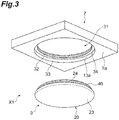
- the power transmitter 2 includes a power transmission coil device 4 for wireless power transfer buried in the road R of the parking lot, etc.
- the power transmission coil device 4 has a shape of a flat rectangular parallelepiped or a frustum.
- the power transmitter 2 generates desired alternating current (AC) power from a direct current (DC) power source or an AC power source, and transmits the generated AC power to the power receiver 3.
- the power transmitter 2 further includes a controller, an inverter, etc. (none of which is illustrated).
- the power receiver 3 is attached to a bottom surface (chassis) of a vehicle body of the electric vehicle EV, and includes a power reception coil device 5 for wireless power transfer facing the power transmission coil device 4.
- a size and/or a shape of the coil device 4 may be different from a size and/or a shape of the power reception coil device 5.
- a size and/or a shape of the attachment portion 6 are different from a size and/or a shape of the attachment portion 7.
- the power transmission coil device 4 may be provided to protrude upward from the road R using another fixing scheme (not illustrated).
- a circular and annular space 24a is formed inside the cylindrical portion 24.
- the space 24a is used as a storing space for a control device, etc.
- the shield portion 22 forms a circular shape, a rectangular (polygonal) shield portion may be employed.
- the disclosure is not restricted to a case in which the shield portion 22 has a shield function. In terms of attachment of the coil devices 4 and 5, the shield portion 22 may be formed using resin, etc. and not have the shield function.
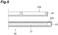
- the whole coil device 5 in the thickness direction is accommodated in the coil accommodation portion 31 and buried inside the attachment portion 7. More specifically, the whole housing 20 of the coil device 5 is accommodated in the housing accommodation portion 33. As illustrated in FIGS. 2A and 2B , a surface 5a of the coil device 5 is flush with the lower surface 7a of the attachment portion 7.
- the housing accommodation portion 33 is provided in the attachment portion 7, a foreign material such as dirt, grit, etc. rarely enters the gap between the attachment portion 7 and the coil device 5. Further, since the whole housing 20 of the coil device 5 is accommodated in the housing accommodation portion 33, a length in which the coil device 5 protrudes from the lower surface 7a of the attachment portion 7 may be decreased. When the coil device 5 is flush with the lower surface 7a of the attachment portion 7 as described above, air resistance is reduced when the electric vehicle EV is driven. In addition, the coil device 5 may be prevented from touching a projection on a road such as a curb.
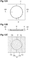
- an attachment structure XF including an attachment portion 7F which is divided into two parts and includes a division plate 7Fa and a division plate 7Fb, and a coil device 5F provided with an engaged portion 53 between disc-shaped flange portions 55 and 55.
- a key way 54a is provided in a semi-circular arc-shaped holding portion 54 of the division plate 7Fa
- a key way 54b is provided in a semi-circular arc-shaped holding portion 54 of the division plate 7Fb.
- the key way 54a and the key way 54b have different sizes (widths).
- a key rib 53a matching the key way 54a and a key rib 53b matching the key way 54b arc provided in the engaged portion 53.
Landscapes
- Engineering & Computer Science (AREA)
- Power Engineering (AREA)
- Mechanical Engineering (AREA)
- Transportation (AREA)
- Computer Networks & Wireless Communication (AREA)
- Life Sciences & Earth Sciences (AREA)
- Sustainable Development (AREA)
- Sustainable Energy (AREA)
- Electric Propulsion And Braking For Vehicles (AREA)
- Current-Collector Devices For Electrically Propelled Vehicles (AREA)
- Charge And Discharge Circuits For Batteries Or The Like (AREA)
Applications Claiming Priority (2)
| Application Number | Priority Date | Filing Date | Title |
|---|---|---|---|
| JP2015018720A JP6485080B2 (ja) | 2015-02-02 | 2015-02-02 | コイル装置の取付構造およびコイル装置 |
| PCT/JP2015/083916 WO2016125378A1 (ja) | 2015-02-02 | 2015-12-02 | コイル装置の取付構造およびコイル装置 |
Publications (3)
| Publication Number | Publication Date |
|---|---|
| EP3255643A1 true EP3255643A1 (de) | 2017-12-13 |
| EP3255643A4 EP3255643A4 (de) | 2018-10-17 |
| EP3255643B1 EP3255643B1 (de) | 2020-07-29 |
Family
ID=56563735
Family Applications (1)
| Application Number | Title | Priority Date | Filing Date |
|---|---|---|---|
| EP15881195.0A Active EP3255643B1 (de) | 2015-02-02 | 2015-12-02 | Befestigungsstruktur für spulenvorrichtungen sowie spulenvorrichtung |
Country Status (5)
| Country | Link |
|---|---|
| US (1) | US10607761B2 (de) |
| EP (1) | EP3255643B1 (de) |
| JP (1) | JP6485080B2 (de) |
| CN (1) | CN107210116A (de) |
| WO (1) | WO2016125378A1 (de) |
Families Citing this family (17)
| Publication number | Priority date | Publication date | Assignee | Title |
|---|---|---|---|---|
| US10643787B2 (en) * | 2015-02-11 | 2020-05-05 | Fu Da Tong Technology Co., Ltd. | Induction type power supply system and coil module thereof |
| DE102015223615B4 (de) * | 2015-11-30 | 2025-03-20 | Bayerische Motoren Werke Aktiengesellschaft | Sekundärspuleneinheit mit einer Service-Öffnung |
| JP6589759B2 (ja) | 2016-07-07 | 2019-10-16 | 株式会社Ihi | コイル装置 |
| JP6593311B2 (ja) * | 2016-11-28 | 2019-10-23 | トヨタ自動車株式会社 | 車両下部構造 |
| WO2019068366A1 (de) * | 2017-10-06 | 2019-04-11 | Sew-Eurodrive Gmbh & Co. Kg | System zur berührungslosen übertragung von elektrischer energie an ein mobilteil |
| US10513198B2 (en) * | 2018-03-14 | 2019-12-24 | Ford Global Technologies, Llc | Electrified vehicle wireless charging system and charging method |
| JP7087664B2 (ja) | 2018-05-17 | 2022-06-21 | 株式会社Ihi | コイル装置 |
| CN112352367B (zh) * | 2018-06-29 | 2024-02-23 | 日产自动车株式会社 | 车辆用非接触供电系统 |
| KR102569722B1 (ko) * | 2018-07-09 | 2023-08-23 | 삼성전자주식회사 | 전자장치 |
| US11011921B2 (en) | 2018-12-31 | 2021-05-18 | Scosche Industries, Inc. | Inductive charger with rotatable magnetic mount |
| JP7183888B2 (ja) * | 2019-03-19 | 2022-12-06 | トヨタ自動車株式会社 | 車両下部構造 |
| US20220059274A1 (en) * | 2020-08-21 | 2022-02-24 | Astec International Limited | Adjustable Spacer For Magnetic Transformers And Inductors |
| USD1038924S1 (en) | 2021-12-08 | 2024-08-13 | Scosche Industries, Inc. | Magnetic device mount |
| USD1006010S1 (en) | 2021-12-30 | 2023-11-28 | Scosche Industries, Inc. | Magnetic device mounting head |
| US12452355B2 (en) | 2022-01-26 | 2025-10-21 | Scosche Industries, Inc. | Container magnetic device mount |
| USD1073440S1 (en) | 2023-06-09 | 2025-05-06 | Scosche Industries, Inc. | Container magnetic device mount |
| JP2025004624A (ja) * | 2023-06-26 | 2025-01-15 | 本田技研工業株式会社 | コイルユニット |
Family Cites Families (21)
| Publication number | Priority date | Publication date | Assignee | Title |
|---|---|---|---|---|
| JP3398880B2 (ja) | 1995-09-14 | 2003-04-21 | オムロン株式会社 | 無線電力伝送装置 |
| CN1825665A (zh) * | 2005-02-25 | 2006-08-30 | 深圳富泰宏精密工业有限公司 | 电池盖结构 |
| JP2007194282A (ja) | 2006-01-17 | 2007-08-02 | Sumida Corporation | コイル部品 |
| JP4356844B2 (ja) | 2006-10-05 | 2009-11-04 | 昭和飛行機工業株式会社 | 非接触給電装置 |
| JP5308127B2 (ja) | 2008-11-17 | 2013-10-09 | 株式会社豊田中央研究所 | 給電システム |
| US8242741B2 (en) * | 2008-12-18 | 2012-08-14 | Motorola Mobility Llc | Systems, apparatus and devices for wireless charging of electronic devices |
| JP2010182499A (ja) * | 2009-02-04 | 2010-08-19 | Sharp Corp | 照明装置 |
| CN201369211Y (zh) | 2009-03-23 | 2009-12-23 | 佛山市南海展晴玩具有限公司 | 带密封槽的电子变压器塑料外壳 |
| US9124308B2 (en) * | 2009-05-12 | 2015-09-01 | Kimball International, Inc. | Furniture with wireless power |
| US8061864B2 (en) * | 2009-05-12 | 2011-11-22 | Kimball International, Inc. | Furniture with wireless power |
| JP5240786B2 (ja) | 2009-08-25 | 2013-07-17 | 国立大学法人埼玉大学 | 非接触給電装置 |
| US8482160B2 (en) * | 2009-09-16 | 2013-07-09 | L & P Property Management Company | Inductively coupled power module and circuit |
| JP2011204836A (ja) * | 2010-03-25 | 2011-10-13 | Toyota Motor Corp | コイルユニット、非接触電力受電装置、非接触電力送電装置、および車両 |
| KR101842308B1 (ko) * | 2010-10-29 | 2018-03-26 | 퀄컴 인코포레이티드 | 커플링된 기생 공진기들을 통한 무선 에너지 전송 |
| US20130057203A1 (en) * | 2011-03-01 | 2013-03-07 | Neil Jones | Assembly for mounting an inductive charger base station to a furniture work surface |
| JP2012222956A (ja) * | 2011-04-08 | 2012-11-12 | Toyota Motor Corp | 車両側コイルユニット、設備側コイルユニットおよび電力伝送システム |
| JP2012254782A (ja) * | 2011-05-17 | 2012-12-27 | Nissan Motor Co Ltd | 非接触充電器の取付構造 |
| US8760253B2 (en) | 2012-01-17 | 2014-06-24 | Delphi Technologies, Inc. | Electrical coil assembly including a ferrite layer and a thermally-conductive silicone layer |
| JP6009174B2 (ja) * | 2012-02-23 | 2016-10-19 | 矢崎総業株式会社 | 非接触給電システム用シールドケース及び非接触給電システム |
| JP6298601B2 (ja) | 2013-07-12 | 2018-03-20 | 株式会社日立ハイテクノロジーズ | 荷電粒子線装置 |
| US9369004B2 (en) * | 2014-06-25 | 2016-06-14 | L & P Property Management Company | Inductive-charging grommet for furniture |
-
2015
- 2015-02-02 JP JP2015018720A patent/JP6485080B2/ja active Active
- 2015-12-02 CN CN201580074737.0A patent/CN107210116A/zh active Pending
- 2015-12-02 WO PCT/JP2015/083916 patent/WO2016125378A1/ja not_active Ceased
- 2015-12-02 EP EP15881195.0A patent/EP3255643B1/de active Active
- 2015-12-02 US US15/547,415 patent/US10607761B2/en active Active
Also Published As
| Publication number | Publication date |
|---|---|
| EP3255643B1 (de) | 2020-07-29 |
| JP2016143773A (ja) | 2016-08-08 |
| WO2016125378A1 (ja) | 2016-08-11 |
| EP3255643A4 (de) | 2018-10-17 |
| US20180025826A1 (en) | 2018-01-25 |
| US10607761B2 (en) | 2020-03-31 |
| CN107210116A (zh) | 2017-09-26 |
| JP6485080B2 (ja) | 2019-03-20 |
Similar Documents
| Publication | Publication Date | Title |
|---|---|---|
| EP3255643B1 (de) | Befestigungsstruktur für spulenvorrichtungen sowie spulenvorrichtung | |
| EP3171375B1 (de) | Spulenvorrichtung | |
| US11322984B2 (en) | Coil device | |
| EP3206281B1 (de) | Stromempfangsspulenvorrichtung und drahtloses stromversorgungssystem | |
| US9895988B2 (en) | Electricity supply device, electricity reception device, and electricity supply system | |
| EP3217514B1 (de) | Spulenvorrichtung, drahtloses stromübertragungssystem sowie magnetisches hilfselement | |
| JP6480976B2 (ja) | 非接触受電装置 | |
| US20180311640A1 (en) | Reactor including end plate | |
| JP6232191B2 (ja) | 給電部、受電部及び給電システム | |
| US20180278094A1 (en) | Console box | |
| US9966796B2 (en) | Power reception device and power transmission device | |
| US12278497B2 (en) | Wireless charging assembly | |
| US10748695B2 (en) | Coil device | |
| US10075010B2 (en) | Tablet connection system | |
| JP6028757B2 (ja) | 受電装置および送電装置 | |
| JP2019036626A (ja) | コイルユニット | |
| US20190392979A1 (en) | Electromagnetic device including iron core supporting structure | |
| US12459378B2 (en) | Coil device, and contactless power supply system |
Legal Events
| Date | Code | Title | Description |
|---|---|---|---|
| STAA | Information on the status of an ep patent application or granted ep patent |
Free format text: STATUS: THE INTERNATIONAL PUBLICATION HAS BEEN MADE |
|
| PUAI | Public reference made under article 153(3) epc to a published international application that has entered the european phase |
Free format text: ORIGINAL CODE: 0009012 |
|
| STAA | Information on the status of an ep patent application or granted ep patent |
Free format text: STATUS: REQUEST FOR EXAMINATION WAS MADE |
|
| 17P | Request for examination filed |
Effective date: 20170809 |
|
| AK | Designated contracting states |
Kind code of ref document: A1 Designated state(s): AL AT BE BG CH CY CZ DE DK EE ES FI FR GB GR HR HU IE IS IT LI LT LU LV MC MK MT NL NO PL PT RO RS SE SI SK SM TR |
|
| AX | Request for extension of the european patent |
Extension state: BA ME |
|
| DAV | Request for validation of the european patent (deleted) | ||
| DAX | Request for extension of the european patent (deleted) | ||
| A4 | Supplementary search report drawn up and despatched |
Effective date: 20180914 |
|
| RIC1 | Information provided on ipc code assigned before grant |
Ipc: H01F 27/06 20060101AFI20180911BHEP Ipc: B60M 7/00 20060101ALI20180911BHEP Ipc: B60L 5/00 20060101ALI20180911BHEP Ipc: H01F 38/14 20060101ALI20180911BHEP Ipc: H01F 27/02 20060101ALI20180911BHEP Ipc: B60L 11/18 20060101ALI20180911BHEP Ipc: H02J 7/02 20160101ALI20180911BHEP |
|
| STAA | Information on the status of an ep patent application or granted ep patent |
Free format text: STATUS: EXAMINATION IS IN PROGRESS |
|
| 17Q | First examination report despatched |
Effective date: 20190425 |
|
| REG | Reference to a national code |
Ref country code: DE Ref legal event code: R079 Ref document number: 602015056706 Country of ref document: DE Free format text: PREVIOUS MAIN CLASS: H01F0027060000 Ipc: H01F0038140000 |
|
| RIC1 | Information provided on ipc code assigned before grant |
Ipc: B60L 50/50 20190101ALI20200122BHEP Ipc: H01F 38/14 20060101AFI20200122BHEP Ipc: H01F 27/02 20060101ALI20200122BHEP Ipc: H01F 27/06 20060101ALI20200122BHEP Ipc: H02J 50/10 20160101ALI20200122BHEP Ipc: H02J 7/02 20160101ALI20200122BHEP Ipc: H02J 7/00 20060101ALI20200122BHEP Ipc: B60L 5/00 20060101ALI20200122BHEP Ipc: B60M 7/00 20060101ALI20200122BHEP |
|
| GRAP | Despatch of communication of intention to grant a patent |
Free format text: ORIGINAL CODE: EPIDOSNIGR1 |
|
| STAA | Information on the status of an ep patent application or granted ep patent |
Free format text: STATUS: GRANT OF PATENT IS INTENDED |
|
| RIN1 | Information on inventor provided before grant (corrected) |
Inventor name: UEDA, AKIO Inventor name: NISHIMURA, KENJI |
|
| INTG | Intention to grant announced |
Effective date: 20200302 |
|
| GRAS | Grant fee paid |
Free format text: ORIGINAL CODE: EPIDOSNIGR3 |
|
| GRAA | (expected) grant |
Free format text: ORIGINAL CODE: 0009210 |
|
| STAA | Information on the status of an ep patent application or granted ep patent |
Free format text: STATUS: THE PATENT HAS BEEN GRANTED |
|
| AK | Designated contracting states |
Kind code of ref document: B1 Designated state(s): AL AT BE BG CH CY CZ DE DK EE ES FI FR GB GR HR HU IE IS IT LI LT LU LV MC MK MT NL NO PL PT RO RS SE SI SK SM TR |
|
| REG | Reference to a national code |
Ref country code: CH Ref legal event code: EP |
|
| REG | Reference to a national code |
Ref country code: AT Ref legal event code: REF Ref document number: 1296766 Country of ref document: AT Kind code of ref document: T Effective date: 20200815 |
|
| REG | Reference to a national code |
Ref country code: IE Ref legal event code: FG4D |
|
| REG | Reference to a national code |
Ref country code: DE Ref legal event code: R096 Ref document number: 602015056706 Country of ref document: DE |
|
| REG | Reference to a national code |
Ref country code: LT Ref legal event code: MG4D |
|
| REG | Reference to a national code |
Ref country code: NL Ref legal event code: MP Effective date: 20200729 |
|
| REG | Reference to a national code |
Ref country code: AT Ref legal event code: MK05 Ref document number: 1296766 Country of ref document: AT Kind code of ref document: T Effective date: 20200729 |
|
| PG25 | Lapsed in a contracting state [announced via postgrant information from national office to epo] |
Ref country code: PT Free format text: LAPSE BECAUSE OF FAILURE TO SUBMIT A TRANSLATION OF THE DESCRIPTION OR TO PAY THE FEE WITHIN THE PRESCRIBED TIME-LIMIT Effective date: 20201130 Ref country code: SE Free format text: LAPSE BECAUSE OF FAILURE TO SUBMIT A TRANSLATION OF THE DESCRIPTION OR TO PAY THE FEE WITHIN THE PRESCRIBED TIME-LIMIT Effective date: 20200729 Ref country code: HR Free format text: LAPSE BECAUSE OF FAILURE TO SUBMIT A TRANSLATION OF THE DESCRIPTION OR TO PAY THE FEE WITHIN THE PRESCRIBED TIME-LIMIT Effective date: 20200729 Ref country code: GR Free format text: LAPSE BECAUSE OF FAILURE TO SUBMIT A TRANSLATION OF THE DESCRIPTION OR TO PAY THE FEE WITHIN THE PRESCRIBED TIME-LIMIT Effective date: 20201030 Ref country code: FI Free format text: LAPSE BECAUSE OF FAILURE TO SUBMIT A TRANSLATION OF THE DESCRIPTION OR TO PAY THE FEE WITHIN THE PRESCRIBED TIME-LIMIT Effective date: 20200729 Ref country code: BG Free format text: LAPSE BECAUSE OF FAILURE TO SUBMIT A TRANSLATION OF THE DESCRIPTION OR TO PAY THE FEE WITHIN THE PRESCRIBED TIME-LIMIT Effective date: 20201029 Ref country code: LT Free format text: LAPSE BECAUSE OF FAILURE TO SUBMIT A TRANSLATION OF THE DESCRIPTION OR TO PAY THE FEE WITHIN THE PRESCRIBED TIME-LIMIT Effective date: 20200729 Ref country code: AT Free format text: LAPSE BECAUSE OF FAILURE TO SUBMIT A TRANSLATION OF THE DESCRIPTION OR TO PAY THE FEE WITHIN THE PRESCRIBED TIME-LIMIT Effective date: 20200729 Ref country code: ES Free format text: LAPSE BECAUSE OF FAILURE TO SUBMIT A TRANSLATION OF THE DESCRIPTION OR TO PAY THE FEE WITHIN THE PRESCRIBED TIME-LIMIT Effective date: 20200729 Ref country code: NO Free format text: LAPSE BECAUSE OF FAILURE TO SUBMIT A TRANSLATION OF THE DESCRIPTION OR TO PAY THE FEE WITHIN THE PRESCRIBED TIME-LIMIT Effective date: 20201029 |
|
| PG25 | Lapsed in a contracting state [announced via postgrant information from national office to epo] |
Ref country code: IS Free format text: LAPSE BECAUSE OF FAILURE TO SUBMIT A TRANSLATION OF THE DESCRIPTION OR TO PAY THE FEE WITHIN THE PRESCRIBED TIME-LIMIT Effective date: 20201129 Ref country code: PL Free format text: LAPSE BECAUSE OF FAILURE TO SUBMIT A TRANSLATION OF THE DESCRIPTION OR TO PAY THE FEE WITHIN THE PRESCRIBED TIME-LIMIT Effective date: 20200729 Ref country code: RS Free format text: LAPSE BECAUSE OF FAILURE TO SUBMIT A TRANSLATION OF THE DESCRIPTION OR TO PAY THE FEE WITHIN THE PRESCRIBED TIME-LIMIT Effective date: 20200729 Ref country code: LV Free format text: LAPSE BECAUSE OF FAILURE TO SUBMIT A TRANSLATION OF THE DESCRIPTION OR TO PAY THE FEE WITHIN THE PRESCRIBED TIME-LIMIT Effective date: 20200729 |
|
| PG25 | Lapsed in a contracting state [announced via postgrant information from national office to epo] |
Ref country code: NL Free format text: LAPSE BECAUSE OF FAILURE TO SUBMIT A TRANSLATION OF THE DESCRIPTION OR TO PAY THE FEE WITHIN THE PRESCRIBED TIME-LIMIT Effective date: 20200729 |
|
| PG25 | Lapsed in a contracting state [announced via postgrant information from national office to epo] |
Ref country code: IT Free format text: LAPSE BECAUSE OF FAILURE TO SUBMIT A TRANSLATION OF THE DESCRIPTION OR TO PAY THE FEE WITHIN THE PRESCRIBED TIME-LIMIT Effective date: 20200729 Ref country code: DK Free format text: LAPSE BECAUSE OF FAILURE TO SUBMIT A TRANSLATION OF THE DESCRIPTION OR TO PAY THE FEE WITHIN THE PRESCRIBED TIME-LIMIT Effective date: 20200729 Ref country code: CZ Free format text: LAPSE BECAUSE OF FAILURE TO SUBMIT A TRANSLATION OF THE DESCRIPTION OR TO PAY THE FEE WITHIN THE PRESCRIBED TIME-LIMIT Effective date: 20200729 Ref country code: RO Free format text: LAPSE BECAUSE OF FAILURE TO SUBMIT A TRANSLATION OF THE DESCRIPTION OR TO PAY THE FEE WITHIN THE PRESCRIBED TIME-LIMIT Effective date: 20200729 Ref country code: SM Free format text: LAPSE BECAUSE OF FAILURE TO SUBMIT A TRANSLATION OF THE DESCRIPTION OR TO PAY THE FEE WITHIN THE PRESCRIBED TIME-LIMIT Effective date: 20200729 Ref country code: EE Free format text: LAPSE BECAUSE OF FAILURE TO SUBMIT A TRANSLATION OF THE DESCRIPTION OR TO PAY THE FEE WITHIN THE PRESCRIBED TIME-LIMIT Effective date: 20200729 |
|
| REG | Reference to a national code |
Ref country code: DE Ref legal event code: R097 Ref document number: 602015056706 Country of ref document: DE |
|
| PG25 | Lapsed in a contracting state [announced via postgrant information from national office to epo] |
Ref country code: AL Free format text: LAPSE BECAUSE OF FAILURE TO SUBMIT A TRANSLATION OF THE DESCRIPTION OR TO PAY THE FEE WITHIN THE PRESCRIBED TIME-LIMIT Effective date: 20200729 |
|
| PLBE | No opposition filed within time limit |
Free format text: ORIGINAL CODE: 0009261 |
|
| STAA | Information on the status of an ep patent application or granted ep patent |
Free format text: STATUS: NO OPPOSITION FILED WITHIN TIME LIMIT |
|
| PG25 | Lapsed in a contracting state [announced via postgrant information from national office to epo] |
Ref country code: SK Free format text: LAPSE BECAUSE OF FAILURE TO SUBMIT A TRANSLATION OF THE DESCRIPTION OR TO PAY THE FEE WITHIN THE PRESCRIBED TIME-LIMIT Effective date: 20200729 |
|
| 26N | No opposition filed |
Effective date: 20210430 |
|
| REG | Reference to a national code |
Ref country code: CH Ref legal event code: PL |
|
| GBPC | Gb: european patent ceased through non-payment of renewal fee |
Effective date: 20201202 |
|
| PG25 | Lapsed in a contracting state [announced via postgrant information from national office to epo] |
Ref country code: SI Free format text: LAPSE BECAUSE OF FAILURE TO SUBMIT A TRANSLATION OF THE DESCRIPTION OR TO PAY THE FEE WITHIN THE PRESCRIBED TIME-LIMIT Effective date: 20200729 Ref country code: MC Free format text: LAPSE BECAUSE OF FAILURE TO SUBMIT A TRANSLATION OF THE DESCRIPTION OR TO PAY THE FEE WITHIN THE PRESCRIBED TIME-LIMIT Effective date: 20200729 |
|
| REG | Reference to a national code |
Ref country code: BE Ref legal event code: MM Effective date: 20201231 |
|
| PG25 | Lapsed in a contracting state [announced via postgrant information from national office to epo] |
Ref country code: IE Free format text: LAPSE BECAUSE OF NON-PAYMENT OF DUE FEES Effective date: 20201202 Ref country code: FR Free format text: LAPSE BECAUSE OF NON-PAYMENT OF DUE FEES Effective date: 20201231 Ref country code: LU Free format text: LAPSE BECAUSE OF NON-PAYMENT OF DUE FEES Effective date: 20201202 |
|
| PG25 | Lapsed in a contracting state [announced via postgrant information from national office to epo] |
Ref country code: GB Free format text: LAPSE BECAUSE OF NON-PAYMENT OF DUE FEES Effective date: 20201202 Ref country code: LI Free format text: LAPSE BECAUSE OF NON-PAYMENT OF DUE FEES Effective date: 20201231 Ref country code: CH Free format text: LAPSE BECAUSE OF NON-PAYMENT OF DUE FEES Effective date: 20201231 |
|
| PG25 | Lapsed in a contracting state [announced via postgrant information from national office to epo] |
Ref country code: IS Free format text: LAPSE BECAUSE OF FAILURE TO SUBMIT A TRANSLATION OF THE DESCRIPTION OR TO PAY THE FEE WITHIN THE PRESCRIBED TIME-LIMIT Effective date: 20201129 Ref country code: TR Free format text: LAPSE BECAUSE OF FAILURE TO SUBMIT A TRANSLATION OF THE DESCRIPTION OR TO PAY THE FEE WITHIN THE PRESCRIBED TIME-LIMIT Effective date: 20200729 Ref country code: MT Free format text: LAPSE BECAUSE OF FAILURE TO SUBMIT A TRANSLATION OF THE DESCRIPTION OR TO PAY THE FEE WITHIN THE PRESCRIBED TIME-LIMIT Effective date: 20200729 Ref country code: CY Free format text: LAPSE BECAUSE OF FAILURE TO SUBMIT A TRANSLATION OF THE DESCRIPTION OR TO PAY THE FEE WITHIN THE PRESCRIBED TIME-LIMIT Effective date: 20200729 |
|
| PG25 | Lapsed in a contracting state [announced via postgrant information from national office to epo] |
Ref country code: MK Free format text: LAPSE BECAUSE OF FAILURE TO SUBMIT A TRANSLATION OF THE DESCRIPTION OR TO PAY THE FEE WITHIN THE PRESCRIBED TIME-LIMIT Effective date: 20200729 |
|
| PG25 | Lapsed in a contracting state [announced via postgrant information from national office to epo] |
Ref country code: BE Free format text: LAPSE BECAUSE OF NON-PAYMENT OF DUE FEES Effective date: 20201231 |
|
| PGFP | Annual fee paid to national office [announced via postgrant information from national office to epo] |
Ref country code: DE Payment date: 20251126 Year of fee payment: 11 |