EP3255643A1 - Attachment structure for coil devices and coil device - Google Patents
Attachment structure for coil devices and coil device Download PDFInfo
- Publication number
- EP3255643A1 EP3255643A1 EP15881195.0A EP15881195A EP3255643A1 EP 3255643 A1 EP3255643 A1 EP 3255643A1 EP 15881195 A EP15881195 A EP 15881195A EP 3255643 A1 EP3255643 A1 EP 3255643A1
- Authority
- EP
- European Patent Office
- Prior art keywords
- coil device
- attachment
- engaged
- coil
- holding portion
- Prior art date
- Legal status (The legal status is an assumption and is not a legal conclusion. Google has not performed a legal analysis and makes no representation as to the accuracy of the status listed.)
- Granted
Links
- 230000004308 accommodation Effects 0.000 claims description 20
- 230000002093 peripheral effect Effects 0.000 claims description 10
- 239000000463 material Substances 0.000 description 11
- XEEYBQQBJWHFJM-UHFFFAOYSA-N Iron Chemical compound [Fe] XEEYBQQBJWHFJM-UHFFFAOYSA-N 0.000 description 10
- 230000005540 biological transmission Effects 0.000 description 10
- 230000004907 flux Effects 0.000 description 10
- 230000001681 protective effect Effects 0.000 description 7
- 239000011347 resin Substances 0.000 description 6
- 229920005989 resin Polymers 0.000 description 6
- 229910052742 iron Inorganic materials 0.000 description 5
- 230000035939 shock Effects 0.000 description 5
- 230000000694 effects Effects 0.000 description 4
- 229910052782 aluminium Inorganic materials 0.000 description 3
- XAGFODPZIPBFFR-UHFFFAOYSA-N aluminium Chemical compound [Al] XAGFODPZIPBFFR-UHFFFAOYSA-N 0.000 description 3
- 230000002265 prevention Effects 0.000 description 3
- 239000004020 conductor Substances 0.000 description 2
- 230000003247 decreasing effect Effects 0.000 description 2
- 230000005674 electromagnetic induction Effects 0.000 description 2
- 239000000696 magnetic material Substances 0.000 description 2
- 239000007769 metal material Substances 0.000 description 2
- 230000002829 reductive effect Effects 0.000 description 2
- 230000002441 reversible effect Effects 0.000 description 2
- RYGMFSIKBFXOCR-UHFFFAOYSA-N Copper Chemical compound [Cu] RYGMFSIKBFXOCR-UHFFFAOYSA-N 0.000 description 1
- 230000002411 adverse Effects 0.000 description 1
- 229910052802 copper Inorganic materials 0.000 description 1
- 239000010949 copper Substances 0.000 description 1
- 230000008878 coupling Effects 0.000 description 1
- 238000010168 coupling process Methods 0.000 description 1
- 238000005859 coupling reaction Methods 0.000 description 1
- 230000005347 demagnetization Effects 0.000 description 1
- 238000010586 diagram Methods 0.000 description 1
- 238000000605 extraction Methods 0.000 description 1
- 238000010438 heat treatment Methods 0.000 description 1
- 230000006698 induction Effects 0.000 description 1
- 230000002401 inhibitory effect Effects 0.000 description 1
- 239000011810 insulating material Substances 0.000 description 1
- 230000005415 magnetization Effects 0.000 description 1
- 229910052751 metal Inorganic materials 0.000 description 1
- 239000002184 metal Substances 0.000 description 1
- 230000002269 spontaneous effect Effects 0.000 description 1
- 230000003245 working effect Effects 0.000 description 1
Images


Classifications
-
- H—ELECTRICITY
- H01—ELECTRIC ELEMENTS
- H01F—MAGNETS; INDUCTANCES; TRANSFORMERS; SELECTION OF MATERIALS FOR THEIR MAGNETIC PROPERTIES
- H01F27/00—Details of transformers or inductances, in general
- H01F27/06—Mounting, supporting or suspending transformers, reactors or choke coils not being of the signal type
-
- B—PERFORMING OPERATIONS; TRANSPORTING
- B60—VEHICLES IN GENERAL
- B60L—PROPULSION OF ELECTRICALLY-PROPELLED VEHICLES; SUPPLYING ELECTRIC POWER FOR AUXILIARY EQUIPMENT OF ELECTRICALLY-PROPELLED VEHICLES; ELECTRODYNAMIC BRAKE SYSTEMS FOR VEHICLES IN GENERAL; MAGNETIC SUSPENSION OR LEVITATION FOR VEHICLES; MONITORING OPERATING VARIABLES OF ELECTRICALLY-PROPELLED VEHICLES; ELECTRIC SAFETY DEVICES FOR ELECTRICALLY-PROPELLED VEHICLES
- B60L5/00—Current collectors for power supply lines of electrically-propelled vehicles
-
- B—PERFORMING OPERATIONS; TRANSPORTING
- B60—VEHICLES IN GENERAL
- B60L—PROPULSION OF ELECTRICALLY-PROPELLED VEHICLES; SUPPLYING ELECTRIC POWER FOR AUXILIARY EQUIPMENT OF ELECTRICALLY-PROPELLED VEHICLES; ELECTRODYNAMIC BRAKE SYSTEMS FOR VEHICLES IN GENERAL; MAGNETIC SUSPENSION OR LEVITATION FOR VEHICLES; MONITORING OPERATING VARIABLES OF ELECTRICALLY-PROPELLED VEHICLES; ELECTRIC SAFETY DEVICES FOR ELECTRICALLY-PROPELLED VEHICLES
- B60L50/00—Electric propulsion with power supplied within the vehicle
- B60L50/50—Electric propulsion with power supplied within the vehicle using propulsion power supplied by batteries or fuel cells
- B60L50/60—Electric propulsion with power supplied within the vehicle using propulsion power supplied by batteries or fuel cells using power supplied by batteries
-
- B—PERFORMING OPERATIONS; TRANSPORTING
- B60—VEHICLES IN GENERAL
- B60L—PROPULSION OF ELECTRICALLY-PROPELLED VEHICLES; SUPPLYING ELECTRIC POWER FOR AUXILIARY EQUIPMENT OF ELECTRICALLY-PROPELLED VEHICLES; ELECTRODYNAMIC BRAKE SYSTEMS FOR VEHICLES IN GENERAL; MAGNETIC SUSPENSION OR LEVITATION FOR VEHICLES; MONITORING OPERATING VARIABLES OF ELECTRICALLY-PROPELLED VEHICLES; ELECTRIC SAFETY DEVICES FOR ELECTRICALLY-PROPELLED VEHICLES
- B60L53/00—Methods of charging batteries, specially adapted for electric vehicles; Charging stations or on-board charging equipment therefor; Exchange of energy storage elements in electric vehicles
- B60L53/10—Methods of charging batteries, specially adapted for electric vehicles; Charging stations or on-board charging equipment therefor; Exchange of energy storage elements in electric vehicles characterised by the energy transfer between the charging station and the vehicle
- B60L53/12—Inductive energy transfer
- B60L53/124—Detection or removal of foreign bodies
-
- B—PERFORMING OPERATIONS; TRANSPORTING
- B60—VEHICLES IN GENERAL
- B60L—PROPULSION OF ELECTRICALLY-PROPELLED VEHICLES; SUPPLYING ELECTRIC POWER FOR AUXILIARY EQUIPMENT OF ELECTRICALLY-PROPELLED VEHICLES; ELECTRODYNAMIC BRAKE SYSTEMS FOR VEHICLES IN GENERAL; MAGNETIC SUSPENSION OR LEVITATION FOR VEHICLES; MONITORING OPERATING VARIABLES OF ELECTRICALLY-PROPELLED VEHICLES; ELECTRIC SAFETY DEVICES FOR ELECTRICALLY-PROPELLED VEHICLES
- B60L53/00—Methods of charging batteries, specially adapted for electric vehicles; Charging stations or on-board charging equipment therefor; Exchange of energy storage elements in electric vehicles
- B60L53/10—Methods of charging batteries, specially adapted for electric vehicles; Charging stations or on-board charging equipment therefor; Exchange of energy storage elements in electric vehicles characterised by the energy transfer between the charging station and the vehicle
- B60L53/12—Inductive energy transfer
- B60L53/126—Methods for pairing a vehicle and a charging station, e.g. establishing a one-to-one relation between a wireless power transmitter and a wireless power receiver
-
- B—PERFORMING OPERATIONS; TRANSPORTING
- B60—VEHICLES IN GENERAL
- B60M—POWER SUPPLY LINES, AND DEVICES ALONG RAILS, FOR ELECTRICALLY- PROPELLED VEHICLES
- B60M7/00—Power lines or rails specially adapted for electrically-propelled vehicles of special types, e.g. suspension tramway, ropeway, underground railway
-
- H—ELECTRICITY
- H01—ELECTRIC ELEMENTS
- H01F—MAGNETS; INDUCTANCES; TRANSFORMERS; SELECTION OF MATERIALS FOR THEIR MAGNETIC PROPERTIES
- H01F27/00—Details of transformers or inductances, in general
- H01F27/02—Casings
-
- H—ELECTRICITY
- H01—ELECTRIC ELEMENTS
- H01F—MAGNETS; INDUCTANCES; TRANSFORMERS; SELECTION OF MATERIALS FOR THEIR MAGNETIC PROPERTIES
- H01F38/00—Adaptations of transformers or inductances for specific applications or functions
- H01F38/14—Inductive couplings
-
- H—ELECTRICITY
- H02—GENERATION; CONVERSION OR DISTRIBUTION OF ELECTRIC POWER
- H02J—CIRCUIT ARRANGEMENTS OR SYSTEMS FOR SUPPLYING OR DISTRIBUTING ELECTRIC POWER; SYSTEMS FOR STORING ELECTRIC ENERGY
- H02J50/00—Circuit arrangements or systems for wireless supply or distribution of electric power
- H02J50/10—Circuit arrangements or systems for wireless supply or distribution of electric power using inductive coupling
-
- H—ELECTRICITY
- H02—GENERATION; CONVERSION OR DISTRIBUTION OF ELECTRIC POWER
- H02J—CIRCUIT ARRANGEMENTS OR SYSTEMS FOR SUPPLYING OR DISTRIBUTING ELECTRIC POWER; SYSTEMS FOR STORING ELECTRIC ENERGY
- H02J7/00—Circuit arrangements for charging or depolarising batteries or for supplying loads from batteries
- H02J7/0042—Circuit arrangements for charging or depolarising batteries or for supplying loads from batteries characterised by the mechanical construction
-
- Y—GENERAL TAGGING OF NEW TECHNOLOGICAL DEVELOPMENTS; GENERAL TAGGING OF CROSS-SECTIONAL TECHNOLOGIES SPANNING OVER SEVERAL SECTIONS OF THE IPC; TECHNICAL SUBJECTS COVERED BY FORMER USPC CROSS-REFERENCE ART COLLECTIONS [XRACs] AND DIGESTS
- Y02—TECHNOLOGIES OR APPLICATIONS FOR MITIGATION OR ADAPTATION AGAINST CLIMATE CHANGE
- Y02T—CLIMATE CHANGE MITIGATION TECHNOLOGIES RELATED TO TRANSPORTATION
- Y02T10/00—Road transport of goods or passengers
- Y02T10/60—Other road transportation technologies with climate change mitigation effect
- Y02T10/70—Energy storage systems for electromobility, e.g. batteries
-
- Y—GENERAL TAGGING OF NEW TECHNOLOGICAL DEVELOPMENTS; GENERAL TAGGING OF CROSS-SECTIONAL TECHNOLOGIES SPANNING OVER SEVERAL SECTIONS OF THE IPC; TECHNICAL SUBJECTS COVERED BY FORMER USPC CROSS-REFERENCE ART COLLECTIONS [XRACs] AND DIGESTS
- Y02—TECHNOLOGIES OR APPLICATIONS FOR MITIGATION OR ADAPTATION AGAINST CLIMATE CHANGE
- Y02T—CLIMATE CHANGE MITIGATION TECHNOLOGIES RELATED TO TRANSPORTATION
- Y02T10/00—Road transport of goods or passengers
- Y02T10/60—Other road transportation technologies with climate change mitigation effect
- Y02T10/7072—Electromobility specific charging systems or methods for batteries, ultracapacitors, supercapacitors or double-layer capacitors
-
- Y—GENERAL TAGGING OF NEW TECHNOLOGICAL DEVELOPMENTS; GENERAL TAGGING OF CROSS-SECTIONAL TECHNOLOGIES SPANNING OVER SEVERAL SECTIONS OF THE IPC; TECHNICAL SUBJECTS COVERED BY FORMER USPC CROSS-REFERENCE ART COLLECTIONS [XRACs] AND DIGESTS
- Y02—TECHNOLOGIES OR APPLICATIONS FOR MITIGATION OR ADAPTATION AGAINST CLIMATE CHANGE
- Y02T—CLIMATE CHANGE MITIGATION TECHNOLOGIES RELATED TO TRANSPORTATION
- Y02T90/00—Enabling technologies or technologies with a potential or indirect contribution to GHG emissions mitigation
- Y02T90/10—Technologies relating to charging of electric vehicles
- Y02T90/14—Plug-in electric vehicles
Definitions
- a fixing force for fixing a coil device becomes a point load corresponding to each bolt. Then, when torsion or an external shock is applied to the coil device, there is a possibility that a force may not be dispersed, and load may be concentrated on and locally applied to a particular bolt.
- an attachment structure capable of evenly dispersing a fixing force for a coil device, and for a coil device attachable using such a structure.
- a side end portion, the side end being in a direction orthogonal to the axis, of the coil portion accommodated in the housing is separated from a side surface portion of the housing in the orthogonal direction by a first gap, the side surface portion is separated from a peripheral surface of the housing accommodation portion in the orthogonal direction by a second gap, and the first gap is larger than the second gap.
- the coil portion is separated from the attachment portion by the first gap.
- a coil device is a flat coil device having a coil portion and being attached to an attachment portion, the coil device including a cylindrical engaged portion engaged with a cylindrical holding portion provided in the attachment portion, wherein the engaged portion is disposed along an axis extending in a thickness direction of the coil device, and configured to be engaged over an entire circumference thereof with the holding portion disposed along the axis.
- the power transmitter 2 includes a power transmission coil device 4 for wireless power transfer buried in the road R of the parking lot, etc.
- the power transmission coil device 4 has a shape of a flat rectangular parallelepiped or a frustum.
- the power transmitter 2 generates desired alternating current (AC) power from a direct current (DC) power source or an AC power source, and transmits the generated AC power to the power receiver 3.
- the power transmitter 2 further includes a controller, an inverter, etc. (none of which is illustrated).
- the power receiver 3 is attached to a bottom surface (chassis) of a vehicle body of the electric vehicle EV, and includes a power reception coil device 5 for wireless power transfer facing the power transmission coil device 4.
- a size and/or a shape of the coil device 4 may be different from a size and/or a shape of the power reception coil device 5.
- a size and/or a shape of the attachment portion 6 are different from a size and/or a shape of the attachment portion 7.
- the power transmission coil device 4 may be provided to protrude upward from the road R using another fixing scheme (not illustrated).
- a circular and annular space 24a is formed inside the cylindrical portion 24.
- the space 24a is used as a storing space for a control device, etc.
- the shield portion 22 forms a circular shape, a rectangular (polygonal) shield portion may be employed.
- the disclosure is not restricted to a case in which the shield portion 22 has a shield function. In terms of attachment of the coil devices 4 and 5, the shield portion 22 may be formed using resin, etc. and not have the shield function.
- the whole coil device 5 in the thickness direction is accommodated in the coil accommodation portion 31 and buried inside the attachment portion 7. More specifically, the whole housing 20 of the coil device 5 is accommodated in the housing accommodation portion 33. As illustrated in FIGS. 2A and 2B , a surface 5a of the coil device 5 is flush with the lower surface 7a of the attachment portion 7.
- the housing accommodation portion 33 is provided in the attachment portion 7, a foreign material such as dirt, grit, etc. rarely enters the gap between the attachment portion 7 and the coil device 5. Further, since the whole housing 20 of the coil device 5 is accommodated in the housing accommodation portion 33, a length in which the coil device 5 protrudes from the lower surface 7a of the attachment portion 7 may be decreased. When the coil device 5 is flush with the lower surface 7a of the attachment portion 7 as described above, air resistance is reduced when the electric vehicle EV is driven. In addition, the coil device 5 may be prevented from touching a projection on a road such as a curb.
- an attachment structure XF including an attachment portion 7F which is divided into two parts and includes a division plate 7Fa and a division plate 7Fb, and a coil device 5F provided with an engaged portion 53 between disc-shaped flange portions 55 and 55.
- a key way 54a is provided in a semi-circular arc-shaped holding portion 54 of the division plate 7Fa
- a key way 54b is provided in a semi-circular arc-shaped holding portion 54 of the division plate 7Fb.
- the key way 54a and the key way 54b have different sizes (widths).
- a key rib 53a matching the key way 54a and a key rib 53b matching the key way 54b arc provided in the engaged portion 53.
Landscapes
- Engineering & Computer Science (AREA)
- Power Engineering (AREA)
- Mechanical Engineering (AREA)
- Transportation (AREA)
- Computer Networks & Wireless Communication (AREA)
- Life Sciences & Earth Sciences (AREA)
- Sustainable Development (AREA)
- Sustainable Energy (AREA)
- Electric Propulsion And Braking For Vehicles (AREA)
- Current-Collector Devices For Electrically Propelled Vehicles (AREA)
- Charge And Discharge Circuits For Batteries Or The Like (AREA)
Abstract
Description
- The present disclosure relates to an attachment structure for a coil device, and a coil device. This application is based upon and claims the benefit of priority from the prior Japanese Patent Applications No.
2015-018720, filed on February 2, 2015 - For example, a wireless power transfer system has been known as a system for charging a vehicle-driving battery of an electric vehicle, etc. In this system, a primary coil device (power transmission coil device) is installed on a ground side, a secondary coil device (power reception coil device) is installed on a vehicle side, and charging is performed by wirelessly transmitting power from the primary coil device to the secondary coil device using a principle of electromagnetic induction. For example, as described in Patent Literature 1, a primary coil device in which an electric wire is wound in a spiral shape on one side of a flat disc-shaped magnetic body core and a secondary coil device having the same configuration are disposed to face each other across a gap between coils thereof.
- Various attachment structures for attaching such a coil device to a vehicle, etc. have been known. For example, in a structure described in
Patent Literature 2, a mounting hole is provided in a cover made of a metal material, and a coil device is fixed to a vehicle using bolts, etc. In a structure described inPatent Literature 3, a coil device is fixed to a vehicle, or a coil device is fixed to a support member provided on a vehicle frame using bolts, etc. -
- Patent Literature 1: Japanese Unexamined Patent Publication No.
2008-87733 - Patent Literature 2: Japanese Unexamined Patent Publication No.
2013-153132 - Patent Literature 3: Japanese Unexamined Patent Publication No.
2012-254782 - When the above-described configuration is employed, a fixing force for fixing a coil device becomes a point load corresponding to each bolt. Then, when torsion or an external shock is applied to the coil device, there is a possibility that a force may not be dispersed, and load may be concentrated on and locally applied to a particular bolt. In this regard, there is a desire for an attachment structure capable of evenly dispersing a fixing force for a coil device, and for a coil device attachable using such a structure.
- A fixing structure for a coil device according to an aspect of the disclosure is an attachment structure for a coil device which attaches a flat coil device including a coil portion to an attachment portion, the attachment structure including a cylindrical holding portion provided in the attachment portion to hold the coil device, and a cylindrical engaged portion provided in the coil device and engaged with the holding portion, wherein the holding portion and the engaged portion are disposed along an axis extending in a thickness direction of the coil device, and the engaged portion is engaged over an entire circumference thereof with the holding portion.
- According to some aspects of the disclosure, it is possible to evenly disperse a fixing force for a coil device.
-
-
FIG. 1 is a diagram illustrating an application example of a coil device according to a first embodiment of the disclosure. -
FIG. 2A is a perspective view illustrating an attachment structure for the coil device inFIG. 1 , andFIG. 2B is a cross-sectional view taken along IIB-IIB line ofFIG. 2A . -
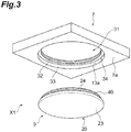
FIG. 3 is an exploded perspective view of the attachment structure ofFIG. 2 . -
FIG. 4A is a plan view of the coil device, andFIGS. 4B and 4C are cross-sectional views of the coil device. -
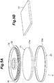
FIG. 5A is an exploded perspective view of the coil device, andFIG. 5B is a perspective view of another coil portion applied instead of a coil portion inFIG. 5A . -
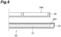
FIG. 6 is a cross-sectional view illustrating a modified example of the coil device. -
FIG. 7A is a perspective view illustrating an attachment structure for a coil device according to a second embodiment, andFIG. 7B is a bottom view ofFIG. 7A . -
FIG. 8A is an exploded perspective view of an attachment structure for a coil device according to a third embodiment,FIG. 8B is a side view of an attachment portion and the coil device ofFIG. 8A, and FIG. 8C is a cross-sectional view of the attachment structure. -
FIG. 9A is an exploded perspective view of an attachment structure for a coil device according to a fourth embodiment,FIG. 9B is a side view of the attachment structure ofFIG 9A, and FIG. 9C is a cross-sectional view of the attachment structure. -
FIG. 10 is an exploded perspective view illustrating an attachment structure for a coil device according to a fifth embodiment. -
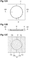
FIG. 11A is a bottom view illustrating an exploded view of an attachment structure for a coil device according to a sixth embodiment,FIG. 11B is a cross-sectional view taken along XIB-XIB line ofFIG. 11A, and FIG. 11C is a cross-sectional view taken along XIC-XIC line ofFIG. 11B . -
FIG. 12A is a bottom view of the attachment structure for the coil device illustrated inFIG. 11A ,FIG. 12B is a cross-sectional view taken along XIIB-XIIB line ofFIG. 12A, and FIG. 12C is a cross-sectional view taken along XIIC-XIIC line ofFIG. 12B . - A fixing structure for a coil device according to an aspect of the disclosure is an attachment structure for a coil device which attaches a flat coil device including a coil portion to an attachment portion, the attachment structure including a cylindrical holding portion provided in the attachment portion to hold the coil device, and a cylindrical engaged portion provided in the coil device and engaged with the holding portion, wherein the holding portion and the engaged portion are disposed along an axis extending in a thickness direction of the coil device, and the engaged portion is engaged over an entire circumference thereof with the holding portion.
- According to the fixing structure for a coil device, the cylindrical holding portion that holds the coil device is provided in the attachment portion to which the coil device is attached. Meanwhile, the cylindrical engaged portion engaged with the holding portion is provided in the coil device. The engaged portion of the coil device is engaged over the entire circumference thereof with the holding portion, and thus a fixing force for the coil device may be evenly dispersed. For example, when an external shock is generated in the coil device or the attachment portion, power thereof may be prevented from being concentrated on a particular position, and the power may be dispersed.
- In some aspects, a screw portion is provided on a peripheral surface of the holding portion and on a peripheral surface of the engaged portion, respectively, and the coil device is fixed to the attachment portion by the engaged portion being screwed into the holding portion by rotation of the coil device around the axis. According to this configuration, when the coil device is rotated, the engaged portion is screwed into the holding portion, and the coil device is fixed to the attachment portion. Therefore, attachment of the coil device is easy.
- In some aspects, the fixing structure for a coil device further includes a positioning portion for fixing the rotated coil device at a predetermined position. According to this configuration, the coil device may be attached such that a position of the coil portion in a rotation direction corresponds to an appropriate position.
- In some aspects, the holding portion is provided in a region recessed from an end surface of the attachment portion in a direction of the axis, and a portion or a whole of the coil device in a thickness direction is buried inside the attachment portion. According to this configuration, since the holding portion is provided in the region recessed from the end surface of the attachment portion, a foreign material such as grit rarely enters a gap between the attachment portion and the coil device.
- In some aspects, the holding portion with which the engaged portion is engaged, and a housing accommodation portion which has a larger diameter than a diameter of the holding portion and accommodates a portion or a whole of a housing of the coil device are provided in the attachment portion. According to this configuration, a foreign material such as grit rarely enters the gap between the attachment portion and the coil device. Further, since the portion or the whole of the housing of the coil device is accommodated in the housing accommodation portion, a length in which the coil device protrudes from the end surface of the attachment portion may be decreased.
- In some aspects, a side end portion, the side end being in a direction orthogonal to the axis, of the coil portion accommodated in the housing is separated from a side surface portion of the housing in the orthogonal direction by a first gap, the side surface portion is separated from a peripheral surface of the housing accommodation portion in the orthogonal direction by a second gap, and the first gap is larger than the second gap. According to this configuration, the coil portion is separated from the attachment portion by the first gap. Thus, when the housing accommodation portion of the attachment portion corresponds to a magnetic member, a magnetic flux from the coil portion may be inhibited from being drawn into the housing accommodation portion. In addition, since the side surface portion of the housing is separated from the peripheral surface of the housing accommodation portion by the relatively small second gap, an effect that a foreign material is prevented from entering the gap increases.
- A coil device according to an aspect of the disclosure is a flat coil device having a coil portion and being attached to an attachment portion, the coil device including a cylindrical engaged portion engaged with a cylindrical holding portion provided in the attachment portion, wherein the engaged portion is disposed along an axis extending in a thickness direction of the coil device, and configured to be engaged over an entire circumference thereof with the holding portion disposed along the axis.
- The holding portion is provided in the attachment portion to which the coil device is attached, and the cylindrical engaged portion engaged with the holding portion provided in the coil device. Since the engaged portion is engaged over the entire circumference thereof with the holding portion, a fixing force for the coil device may be evenly dispersed. For example, when an external shock is generated in the coil device or the attachment portion, power thereof may be prevented from being concentrated on a particular position, and the power may be dispersed.
- Hereinafter, embodiments of the disclosure will be described with reference to drawings. In description of the drawings, a like reference symbol will be assigned to a like component, and a repeated description will be omitted. Hereinafter, a description will be given of a case in which an attachment structure for a coil device according to the disclosure is applied to a coil device for wireless power transfer. The disclosure is not restricted to the coil device for wireless power transfer, and may be applied to, for example, an induction heating system.
- A description will be given of a wireless power transfer system 1 to which a coil device and an attachment structure therefor of the present embodiment are applied with reference to
FIG. 1 . The wireless power transfer system 1 is a system for supplying power from apower transmitter 2 to apower receiver 3. For example, thepower transmitter 2 and thepower receiver 3 are separated from each other in a vertical direction. For example, thepower transmitter 2 is installed on a road R of a parking lot, etc. For example, thepower receiver 3 is mounted in an electric vehicle EV. The wireless power transfer system 1 is configured to supply power to the electric vehicle EV arriving at the parking lot, etc. using a magnetic resonance scheme, an electromagnetic induction scheme, etc. - The
power transmitter 2 includes a powertransmission coil device 4 for wireless power transfer buried in the road R of the parking lot, etc. The powertransmission coil device 4 has a shape of a flat rectangular parallelepiped or a frustum. Thepower transmitter 2 generates desired alternating current (AC) power from a direct current (DC) power source or an AC power source, and transmits the generated AC power to thepower receiver 3. Thepower transmitter 2 further includes a controller, an inverter, etc. (none of which is illustrated). For example, thepower receiver 3 is attached to a bottom surface (chassis) of a vehicle body of the electric vehicle EV, and includes a powerreception coil device 5 for wireless power transfer facing the powertransmission coil device 4. The powerreception coil device 5 has a shape of a flat rectangular parallelepiped or a frustum. Thepower receiver 3 receives power from thepower transmitter 2, and supplies power to a load (for example, a battery). Thepower receiver 3 further includes a controller, a rectifier, etc. (none of which is illustrated). Hereinafter, the powertransmission coil device 4 and the powerreception coil device 5 will be referred to as acoil device 4 and acoil device 5, respectively. - In the wireless power transfer system 1, the
coil device 4 is fixed to anattachment portion 6 provided on the road R. Thecoil device 5 is installed in the electric vehicle EV corresponding to a moving body. The powerreception coil device 5 is fixed to anattachment portion 7 provided on the chassis of the electric vehicle EV, etc. An attachment structure X2 is configured by thecoil device 4 and theattachment portion 6, and an attachment structure X1 is configured by thecoil device 5 and theattachment portion 7. The attachment structure X2 and the attachment structure X1 have substantially the same configuration. The powertransmission coil device 4 and theattachment portion 6 of the attachment structure X2 and the powerreception coil device 5 and theattachment portion 7 of the attachment structure X1 are in planar symmetry with respect to a plane orthogonal to an axis L passing through centers thereof. A size and/or a shape of thecoil device 4 may be different from a size and/or a shape of the powerreception coil device 5. In this case, a size and/or a shape of theattachment portion 6 are different from a size and/or a shape of theattachment portion 7. In addition, in thepower transmitter 2, the powertransmission coil device 4 may be provided to protrude upward from the road R using another fixing scheme (not illustrated). - Hereinafter, a description will be given of the attachment structure X1 on the electric vehicle EV side. First, the
coil device 5 will be described with reference toFIG. 4 andFIG. 5 . Thecoil device 5 generates an induced current when a magnetic flux generated in the powertransmission coil device 4 interlinks with thecoil device 5. Thecoil device 5 includes aflat housing 20 and aflat coil portion 21 accommodated in thehousing 20. Thehousing 20 includes a disc-shapedshield portion 22 to which thecoil portion 21 is fixed, and aprotective cover 23 having a bottomed cylindrical shape attached to a lower side of theshield portion 22. Acylindrical portion 24 having a slightly smaller diameter than that of theshield portion 22 is connected to an upper side of theshield portion 22. Thecylindrical portion 24 protrudes upward (toward the vehicle side, that is, theattachment portion 7 side) from theshield portion 22. - The
shield portion 22 and thecylindrical portion 24 are integrally formed. Theshield portion 22 and thecylindrical portion 24 are preferably made of a non-magnetic and conductive material, for example, aluminum or copper. When theshield portion 22 is formed using the non-magnetic and conductive material, theshield portion 22 has a function of inhibiting a magnetic flux between thecoil devices protective cover 23 is made of a magnetic flux transmitting and insulating material (for example, resin). Theshield portion 22, thecylindrical portion 24, and theprotective cover 23 are disposed around the axis L extending in a thickness direction of thehousing 20 such that the axis L corresponds to a center. As illustrated inFIG. 4A and 4B , a circular andannular space 24a is formed inside thecylindrical portion 24. For example, thespace 24a is used as a storing space for a control device, etc. Even though theshield portion 22 forms a circular shape, a rectangular (polygonal) shield portion may be employed. In addition, the disclosure is not restricted to a case in which theshield portion 22 has a shield function. In terms of attachment of thecoil devices shield portion 22 may be formed using resin, etc. and not have the shield function. - The
coil portion 21 is configured to generate an induced current, and includes a thin plate-shaped magnetic body core (magnetic member), a coil wire (conductive wire), and a wire fixing frame (none of which is illustrated). Thecoil portion 21 forms a circular shape. As illustrated inFIG. 5B , a rectangular (polygonal)coil portion 41 may be used. Thecoil portion 21 may correspond to a solenoid type or a circular type. Thecoil portion 21 abuts theshield portion 22 of thehousing 20, and is fixed thereto. Thecoil portion 21 is disposed such that the axis L corresponds to a center. The magnetic body core of thecoil portion 21 reinforces electromagnetic coupling between thecoil devices coil devices - As illustrated in
FIG. 2 andFIG. 3 , theattachment portion 7 corresponding to a frame to which thecoil device 5 is fixed is provided in the attachment structure X1. Theattachment portion 7 may be formed in the chassis, etc. of the electric vehicle EV, or manufactured as a separate body from the chassis, etc. and attached to the chassis, etc. Theattachment portion 7 is made of a material capable of securing strength, for example, iron. Theattachment portion 7 includes abase portion 10 disposed on an upper surface side and a cylindricalcoil enclosing portion 11 connected to a lower side of thebase portion 10. Thebase portion 10 and thecoil enclosing portion 11 are integrally formed. Acoil accommodation portion 31 for accommodating thecoil device 5 is provided inside thecoil enclosing portion 11. - The
coil enclosing portion 11 includes a cylindrical holdingportion forming portion 12 connected to the lower side of thebase portion 10, and a cylindricalhousing enclosing portion 13 connected to a lower side of the holdingportion forming portion 12. An inner diameter of thehousing enclosing portion 13 is larger than an inner diameter of the holdingportion forming portion 12. Thecylindrical portion 24 of thecoil device 5 is accommodated in the holdingportion forming portion 12. On a peripheral surface (inner circumferential surface) of the holdingportion forming portion 12 facing the axis L, screw thread processing is performed, and a holdingportion 32 in which a female screw portion is formed is provided. Ahousing accommodation portion 33 is formed inside thehousing enclosing portion 13, and theshield portion 22 and theprotective cover 23 of thecoil device 5 arc accommodated in thehousing accommodation portion 33. A diameter of thehousing accommodation portion 33 is larger than that of the holdingportion 32. In this way, an annular steppedportion 34 facing downward is formed between the holdingportion 32 and thehousing accommodation portion 33. - In this way, the
attachment portion 7 includes the holdingportion 32 formed in a concave region. In other words, the holdingportion 32 of theattachment portion 7 is provided in a region recessed (a region recessed upward) from alower surface 7a (an end surface in the direction of the axis L) of theattachment portion 7. - Meanwhile, on an outer circumferential surface of the
cylindrical portion 24 of thecoil device 5, screw thread processing is performed, and an engagedportion 40 in which a male screw portion is formed is provided. The holdingportion 32 and the engagedportion 40 are disposed along the axis L extending in a thickness direction of the coil device 5 (to surround the axis L), and the engagedportion 40 may be engaged with the holdingportion 32 provided in theattachment portion 7. For example, thecoil device 5 is gripped using a jig, and the engagedportion 40 is screwed into the holdingportion 32 by being rotated around the axis L. In this way, thecoil device 5 is fixed to theattachment portion 7. The engagedportion 40 is engaged with the holdingportion 32, and the holdingportion 32 holds thecoil device 5 by this engagement. In this way, in the attachment structure X1 employing a screw structure, the engagedportion 40 is engaged over the entire circumference thereof with the holdingportion 32. - While the
coil device 5 is attached to theattachment portion 7, thewhole coil device 5 in the thickness direction is accommodated in thecoil accommodation portion 31 and buried inside theattachment portion 7. More specifically, thewhole housing 20 of thecoil device 5 is accommodated in thehousing accommodation portion 33. As illustrated inFIGS. 2A and 2B , asurface 5a of thecoil device 5 is flush with thelower surface 7a of theattachment portion 7. - As illustrated in
FIG. 2B , aside end portion 21a (a side end portion in a direction orthogonal to the axis L) of thecoil portion 21 accommodated in thehousing 20 is separated from aside surface portion 23a (seeFIG. 4C ) of theprotective cover 23 by a first gap d1 in the orthogonal direction (left-right direction in the figure). Theside surface portion 23a of theprotective cover 23 is separated from an innercircumferential surface 13a of the housing enclosing portion 13 (peripheral surface of the housing accommodation portion 33) by a second gap d2 (seeFIG. 2B ) in the orthogonal direction. Herein, the first gap d1 is larger than the second gap d2. According to this configuration, a gap between thehousing 20 and thehousing enclosing portion 13 is made as small as possible to prevent a foreign material such as dirt, grit, etc. from entering the gap. Further, theside end portion 21a of thecoil portion 21 is separated from the housing enclosing portion 13 (the attachment portion 7) made of iron by a certain distance, thereby reducing an adverse effect on a magnetic flux between thecoil devices housing enclosing portion 13. - According to the
coil device 5 and the attachment structure X1 therefor described above, thecylindrical holding portion 32 that holds thecoil device 5 is provided in theattachment portion 7 of the electric vehicle EV to which theflat coil device 5 is attached, and the cylindrical engagedportion 40 engaged with the holdingportion 32 is provided in thecoil device 5. The engagedportion 40 of thecoil device 5 is engaged over the entire circumference thereof with the holdingportion 32, and thus a fixing force for thecoil device 5 is dispersed evenly (that is, radially over the entire circumference). For example, when an external shock is applied to theattachment portion 7 of the electric vehicle EV, a force thereof may be prevented from being concentrated on several regions, and the force may be dispersed. In addition, when several places of a flat coil device are fixed using bolts as in the past, there is a possibility that a balance (dynamic balance) of a fixing force may be lost due to damage to a bolt hole or a bolt. According to the above-described configuration, such a possibility is eliminated. In addition, a plurality of captive screws, which has been necessary in the past, is unnecessary, a working property is improved, and errors at the time of processing are reduced. Furthermore, a retaining error does not occur. - Since the
coil device 5 is fixed to theattachment portion 7 when thecoil device 5 is rotated and the engagedportion 40 is screwed into the holdingportion 32, attachment of thecoil device 5 is easy. - The holding
portion 32 is provided in the region recessed from thelower surface 7a of theattachment portion 7, and thus a foreign material such as dirt, grit, etc. rarely enters a gap between theattachment portion 7 and thecoil device 5. In this way, an engaged part of the holdingportion 32 and the engagedportion 40 is hidden from an exterior view, and thus a state in which a foreign material is attached to the engaged part, and thecoil device 5 may not be removed does not occur. - Since the
housing accommodation portion 33 is provided in theattachment portion 7, a foreign material such as dirt, grit, etc. rarely enters the gap between theattachment portion 7 and thecoil device 5. Further, since thewhole housing 20 of thecoil device 5 is accommodated in thehousing accommodation portion 33, a length in which thecoil device 5 protrudes from thelower surface 7a of theattachment portion 7 may be decreased. When thecoil device 5 is flush with thelower surface 7a of theattachment portion 7 as described above, air resistance is reduced when the electric vehicle EV is driven. In addition, thecoil device 5 may be prevented from touching a projection on a road such as a curb. - According to the
coil enclosing portion 11 having a double layer structure of the holdingportion forming portion 12 and thehousing enclosing portion 13 having different inner diameters, the holdingportion 32 in which the screw portion is formed is provided in an inner part, and thus thespace 24a on the inside of thecylindrical portion 24 in a second layer may be used as a storing space for a precision instrument such as a controller, and such a precision instrument may be protected from an external shock. - In addition, the
coil portion 21 is separated from theattachment portion 7 by the first gap d1. When theattachment portion 7 corresponds to a magnetic member such as iron, there is a possibility that a magnetic flux from thecoil portion 21 may be drawn into theattachment portion 7 which does not contribute to power feeding. In this regard, in the attachment structure X1, when thecoil portion 21 and theattachment portion 7 are separated from each other, a flow of a magnetic flux between thecoil devices coil portion 21 and theattachment portion 7 are adjacent to each other. In addition, since theside surface portion 23a of thehousing 20 is separated from the innercircumferential surface 13a of the housing enclosing portion 13 (peripheral surface of the housing accommodation portion 33) by the relatively small second gap d2, an effect that a foreign material is prevented from entering the gap increases. - Next, a description will be given of a modified mode of the coil device with reference to
FIG. 6 . As illustrated inFIG. 6 , it is possible to employ acoil device 5A in which acylindrical portion 24A and ashield portion 22A are configured as separate bodies. Thecylindrical portion 24A including an engagedportion 40 in which a screw portion is formed may be made of the above-mentioned metal material or another material. Thecylindrical portion 24A may be formed using iron, etc. to ensure strength of thecylindrical portion 24A. Alternatively, weight lightening may be attempted by forming thecylindrical portion 24A using resin, etc. Further, theshield portion 22A may be made of resin, and thecylindrical portion 24A may be made of aluminum, thereby assigning a shield function only to thecylindrical portion 24A. - Next, a description will be given of an attachment structure XB according to a second embodiment with reference to
FIG. 7 . In the above-described embodiment, thecoil portion 21 of thecoil device 5 may correspond to the solenoid type or the circular type. When the circular-type coil portion 21 is employed, a position in a rotation direction around the axis L may not be strictly controlled. However, in the case of an extraction direction of a wire or in which a shape of thecoil portion 21 does not correspond to a perfect circle and corresponds to an ellipse, a rectangle, etc., a predetermined directivity may be necessary. Meanwhile, when the solenoid-type coil portion 21 is employed, and when thecoil portion 21 is rotated by 90 degrees around the axis L, a direction of a magnetic flux line is different. Thus, a position of thecoil portion 21 in the rotation direction is significant. - In this regard, in the embodiment below, a positioning portion for determining a position of a coil device in a rotation direction is provided. The positioning portion is used to fix a rotated
coil device 5B at a predetermined position. In more detail, the positioning portion is configured such that positioning of thecoil device 5B in the rotation direction is performed when thecoil device 5B is attached to anattachment portion 7B. In the embodiment below, when the positioning portion is provided, thecoil device 5B, etc. may be easily attached such that a position of thecoil portion 21 in the rotation direction corresponds to an appropriately position. As illustrated inFIG. 7 , the attachment structure XB that includes thecoil device 5B provided with amark 45 and theattachment portion 7B provided with amark 46 corresponding to themark 45 may be employed as an aspect of the disclosure. In this case, for example, a loosening prevention screw thread may be formed in a holdingportion 32 and an engagedportion 40 such that rotation of thecoil device 5 stops at a target position (a position at which themark 45 matches the mark 46) when thedevice 5 is screwed at specified torque. The loosening prevention screw thread prevents reverse rotation and deviation of fixing resulting from vibration, etc. In the present embodiment, themark 45, themark 46, and the holdingportion 32 and the engagedportion 40 having the loosening prevention screw thread correspond to the positioning portion. - Next, a description will be given of an attachment structure XC according to a third embodiment with reference to
FIG. 8 . As illustrated inFIG. 8 , as an aspect of the disclosure, it is possible to employ the attachment structure XC including anattachment portion 7C, which includes a holdingportion forming portion 12C provided with agroove portion 47 for positioning on an outer circumferential surface, abase portion 10C, and ahousing enclosing portion 13C, and acoil device 5C provided with apush block 48 on an outer circumferential surface of acylindrical portion 24C. For example, thepush block 48 includes a spring and attempts to return to a home position due to an elastic force when thepush block 48 is pushed. In this case, when thecoil device 5C is rotated in a screw direction while thepush block 48 is pushed, and thepush block 48 moves up to a position of thegroove portion 47, thepush block 48 is inserted into thegroove portion 47 by an elastic force thereof. In this way, thecoil device 5C is fixed. Thepush block 48 may move forward and backward by a spring force. When thecoil device 5C is removed, a jig is put into thegroove portion 47 in a lateral direction to push and release thepush block 48 from thegroove portion 47. In the present embodiment, thepush block 48 and thegroove portion 47 correspond to a positioning portion. - Next, a description will be given of an attachment structure XD according to a fourth embodiment with reference to
FIG. 9 . As illustrated inFIG. 9 , as an aspect of the disclosure, it is possible to employ the attachment structure XD including anattachment portion 7D, which includes a holdingportion forming portion 12D provided with ascrew hole portion 49 for locking on an outer circumferential surface, abase portion 10D, and ahousing enclosing portion 13D, and acoil device 5D which includes acylindrical portion 24D providing with ascrew hole portion 43 for locking on an outer circumferential surface. In this case, thecoil device 5D is rotated in a screw direction, and theattachment portion 7D and thecoil device 5D are fastened together at a point at which thescrew hole portion 49 matches thescrew hole portion 43 using a lockingscrew 50 and a jig T, thereby preventing reverse rotation and deviation of fixing of thecoil device 5D. When thecoil device 5D is removed, thecoil device 5D is loosened using the jig T in a lateral direction. In the present embodiment, thescrew hole portion 43, thescrew hole portion 49, and the lockingscrew 50 correspond to a positioning portion. - Next, a description will be given of an attachment structure XE according to a fifth embodiment with reference to
FIG. 10 . As illustrated inFIG. 10 , as an aspect of the disclosure, it is possible to employ the attachment structure XE including anattachment portion 7E provided with amagnet 51 and acoil device 5E which includes acylindrical portion 24E provided with amagnet 52 at a position corresponding to themagnet 51. In this case, ashield portion 22 of thecoil device 5E and theattachment portion 7E correspond to aluminum, resin, etc. not having a magnetic property. When thecoil device 5E is fastened to a certain extent, an attracting force is generated by magnetic forces of the magnets, and thecoil device 5E is fixed at a positioning point. A force resulting from themagnet 51 and themagnet 52 has strength at which movement does not occur by specific vibration or power. When thecoil device 5E is removed, the magnetic force is weakened by demagnetization, etc. In the present embodiment, themagnet 51 and themagnet 52 correspond to a positioning portion. - Next, a description will be given of an attachment structure XF according to a sixth embodiment with reference to
FIG 11 andFIG. 12 . As an aspect of the disclosure, it is possible to employ the attachment structure XF including anattachment portion 7F which is divided into two parts and includes a division plate 7Fa and a division plate 7Fb, and acoil device 5F provided with an engagedportion 53 between disc-shapedflange portions key way 54a is provided in a semi-circular arc-shaped holdingportion 54 of the division plate 7Fa, and akey way 54b is provided in a semi-circular arc-shaped holdingportion 54 of the division plate 7Fb. Thekey way 54a and thekey way 54b have different sizes (widths). Akey rib 53a matching thekey way 54a and akey rib 53b matching thekey way 54b arc provided in the engagedportion 53. - At the time of fixing the
coil device 5F, thecoil device 5F is fit and fixed by enclosing a entire circumference as a regular position only when concavo-convex shapes of keys match each other. Theattachment portion 7 may have a two-division structure or a multi-division structure. However, the concavo-convex shapes or positions of the keys are changed such that thecoil device 5F may not be fixed at a position other than the regular position. For example, different shapes are formed as thekey way 54a and thekey way 54b, and thekey rib 53a and thekey rib 53b described above. According to the attachment structure XF having such an enclosing structure, the engagedportion 53 is engaged over the entire circumference thereof with the holdingportion 54, and thus a fixing force for thecoil device 5F may be evenly dispersed. In the present embodiment, thekey way 54a and thekey way 54b, and thekey rib 53a and thekey rib 53b correspond to a positioning portion. - Hereinbefore, the embodiments of the disclosure have been described. However, the invention is not restricted to the above-described embodiments. For example, the
attachment portion 7 may not be made of iron, and may be made of another metal or resin when strength may be secured. With regard to the first to fifth embodiments, a description has been given of a case in which a female screw is formed in theattachment portion 7 and a male screw is formed in thehousing 20 of thecoil device 5. However, the invention is not restricted to this mode. For example, it is possible to employ an attachment portion which protrudes toward a coil device and in which a male screw is formed on an outer circumferential surface, and a coil device which accommodates the attachment portion and includes a housing in which a female screw is formed on an inner circumferential surface. In addition, with regard to the sixth embodiment, an arrangement relation of the key way (concave shape) of the holdingportion 54 and the key rib (convex shape) of the engagedportion 53 may be reversed. - In the above-described embodiments, the power
reception coil device 5 of thepower receiver 3 has been described. However, the invention may be applied to the powertransmission coil device 4 of thepower transmitter 2. Only a portion of the coil device in the thickness direction may be accommodated inside theattachment portion 7. The steppedportion 34 may not be provided. Only a portion of thehousing 20 in the thickness direction may be accommodated inside theattachment portion 7. In other words, a portion of thecoil device 5 may protrude from thelower surface 7a of theattachment portion 7. - The invention is not restricted to a vehicle body of a vehicle driven on a road, and may be applied to another moving body such as an underwater sailing body.
- According to some aspects of the disclosure, it is possible to evenly disperse a fixing force for a coil device.
-
- 1 wireless power transfer system
- 2 power transmitter
- 3 power receiver
- 4 power transmission coil device
- 5 power reception coil device
- 5A coil device
- 5B coil device
- 5C coil device
- 5D coil device
- 5E coil device
- 5F coil device
- 7 attachment portion
- 7a lower surface (end surface in direction of axis L)
- 7B attachment portion
- 7C attachment portion
- 7D attachment portion
- 7E attachment portion
- 7F attachment portion
- 21 coil portion
- 21a side end portion
- 23 protective cover
- 23a side surface portion
- 24 cylindrical portion
- 24A cylindrical portion
- 24C cylindrical portion
- 24D cylindrical portion
- 24E cylindrical portion
- 32 holding portion
- 33 housing accommodation portion
- 40 engaged portion
- 41 coil portion
- 43 screw hole portion
- 45 mark
- 46 mark
- 47 groove portion
- 48 push block
- 49 screw hole portion
- 50 locking screw
- 51 magnet
- 52 magnet
- 53 engaged portion
- 53a key rib
- 53b key rib
- 54a key way
- 54b key way
- 54 holding portion
- d1 first gap
- d2 second gap
- EV electric vehicle
- L axis
- R road
- X1 attachment structure
- X2 attachment structure
- XB attachment structure
- XC attachment structure
- XD attachment structure
- XE attachment structure
- XF attachment structure
Claims (7)
- An attachment structure for a coil device which attaches a flat coil device including a coil portion to an attachment portion, the attachment structure comprising:a cylindrical holding portion provided in the attachment portion to hold the coil device; anda cylindrical engaged portion provided in the coil device and engaged with the holding portion,wherein the holding portion and the engaged portion are disposed along an axis extending in a thickness direction of the coil device, and the engaged portion is engaged over the entire circumference thereof with the holding portion.
- The attachment structure according to claim 1,
wherein a screw portion is provided on a peripheral surface of the holding portion and on a peripheral surface of the engaged portion, respectively, and
the coil device is fixed to the attachment portion by the engaged portion being screwed into the holding portion by rotation of the coil device around the axis. - The attachment structure according to claim 2, further comprising
a positioning portion for fixing the rotated coil device at a predetermined position. - The attachment structure according to any one of claims 1 to 3,
wherein the holding portion is provided in a region recessed from an end surface of the attachment portion in a direction of the axis, and
a portion or a whole of the coil device in a thickness direction is buried inside the attachment portion. - The attachment structure according to claim 4, wherein the holding portion with which the engaged portion is engaged, and a housing accommodation portion which has a larger diameter than a diameter of the holding portion and accommodates a portion or a whole of a housing of the coil device are provided in the attachment portion.
- The attachment structure according to claim 5,
wherein a side end portion, the side end being in a direction orthogonal to the axis, of the coil portion accommodated in the housing is separated from a side surface portion of the housing in the orthogonal direction by a first gap, and the side surface portion is separated from a peripheral surface of the housing accommodation portion in the orthogonal direction by a second gap, and
the first gap is larger than the second gap. - A flat coil device having a coil portion and being attached to an attachment portion, the coil device comprising
a cylindrical engaged portion engaged with a cylindrical holding portion provided in the attachment portion,
wherein the engaged portion is disposed along an axis extending in a thickness direction of the coil device, and configured to be engaged over the entire circumference thereof with the holding portion disposed along the axis.
Applications Claiming Priority (2)
| Application Number | Priority Date | Filing Date | Title |
|---|---|---|---|
| JP2015018720A JP6485080B2 (en) | 2015-02-02 | 2015-02-02 | Coil device mounting structure and coil device |
| PCT/JP2015/083916 WO2016125378A1 (en) | 2015-02-02 | 2015-12-02 | Attachment structure for coil devices and coil device |
Publications (3)
| Publication Number | Publication Date |
|---|---|
| EP3255643A1 true EP3255643A1 (en) | 2017-12-13 |
| EP3255643A4 EP3255643A4 (en) | 2018-10-17 |
| EP3255643B1 EP3255643B1 (en) | 2020-07-29 |
Family
ID=56563735
Family Applications (1)
| Application Number | Title | Priority Date | Filing Date |
|---|---|---|---|
| EP15881195.0A Active EP3255643B1 (en) | 2015-02-02 | 2015-12-02 | Attachment structure for coil devices and coil device |
Country Status (5)
| Country | Link |
|---|---|
| US (1) | US10607761B2 (en) |
| EP (1) | EP3255643B1 (en) |
| JP (1) | JP6485080B2 (en) |
| CN (1) | CN107210116A (en) |
| WO (1) | WO2016125378A1 (en) |
Families Citing this family (14)
| Publication number | Priority date | Publication date | Assignee | Title |
|---|---|---|---|---|
| US10643787B2 (en) | 2015-02-11 | 2020-05-05 | Fu Da Tong Technology Co., Ltd. | Induction type power supply system and coil module thereof |
| DE102015223615A1 (en) * | 2015-11-30 | 2017-06-01 | Bayerische Motoren Werke Aktiengesellschaft | Secondary coil unit with a service opening |
| JP6589759B2 (en) | 2016-07-07 | 2019-10-16 | 株式会社Ihi | Coil device |
| JP6593311B2 (en) * | 2016-11-28 | 2019-10-23 | トヨタ自動車株式会社 | Vehicle lower structure |
| US10965155B2 (en) * | 2017-10-06 | 2021-03-30 | Sew-Eurodrive Gmbh & Co. Kg | System for non-contact transmission of electrical energy to a mobile part |
| US10513198B2 (en) * | 2018-03-14 | 2019-12-24 | Ford Global Technologies, Llc | Electrified vehicle wireless charging system and charging method |
| JP7087664B2 (en) | 2018-05-17 | 2022-06-21 | 株式会社Ihi | Coil device |
| EP3817191A4 (en) * | 2018-06-29 | 2021-05-12 | Nissan Motor Co., Ltd. | Vehicle non-contact power feeding system |
| KR102569722B1 (en) * | 2018-07-09 | 2023-08-23 | 삼성전자주식회사 | Electronic apparatus |
| US11011921B2 (en) * | 2018-12-31 | 2021-05-18 | Scosche Industries, Inc. | Inductive charger with rotatable magnetic mount |
| JP7183888B2 (en) * | 2019-03-19 | 2022-12-06 | トヨタ自動車株式会社 | vehicle undercarriage |
| US20220059274A1 (en) * | 2020-08-21 | 2022-02-24 | Astec International Limited | Adjustable Spacer For Magnetic Transformers And Inductors |
| USD1038924S1 (en) | 2021-12-08 | 2024-08-13 | Scosche Industries, Inc. | Magnetic device mount |
| USD1006010S1 (en) | 2021-12-30 | 2023-11-28 | Scosche Industries, Inc. | Magnetic device mounting head |
Family Cites Families (21)
| Publication number | Priority date | Publication date | Assignee | Title |
|---|---|---|---|---|
| JP3398880B2 (en) | 1995-09-14 | 2003-04-21 | オムロン株式会社 | Wireless power transmission device |
| CN1825665A (en) * | 2005-02-25 | 2006-08-30 | 深圳富泰宏精密工业有限公司 | Battery lid structure |
| JP2007194282A (en) | 2006-01-17 | 2007-08-02 | Sumida Corporation | Coil component |
| JP4356844B2 (en) | 2006-10-05 | 2009-11-04 | 昭和飛行機工業株式会社 | Non-contact power feeding device |
| JP5308127B2 (en) | 2008-11-17 | 2013-10-09 | 株式会社豊田中央研究所 | Power supply system |
| US8242741B2 (en) * | 2008-12-18 | 2012-08-14 | Motorola Mobility Llc | Systems, apparatus and devices for wireless charging of electronic devices |
| JP2010182499A (en) * | 2009-02-04 | 2010-08-19 | Sharp Corp | Lighting device |
| CN201369211Y (en) | 2009-03-23 | 2009-12-23 | 佛山市南海展晴玩具有限公司 | Electronic transformer plastic housing with sealing groove |
| US8061864B2 (en) * | 2009-05-12 | 2011-11-22 | Kimball International, Inc. | Furniture with wireless power |
| US9124308B2 (en) | 2009-05-12 | 2015-09-01 | Kimball International, Inc. | Furniture with wireless power |
| JP5240786B2 (en) | 2009-08-25 | 2013-07-17 | 国立大学法人埼玉大学 | Non-contact power feeding device |
| US8482160B2 (en) * | 2009-09-16 | 2013-07-09 | L & P Property Management Company | Inductively coupled power module and circuit |
| JP2011204836A (en) * | 2010-03-25 | 2011-10-13 | Toyota Motor Corp | Coil unit, noncontact power receiving device, noncontact power transmitting device, and vehicle |
| CN103249592B (en) * | 2010-10-29 | 2016-06-15 | 高通股份有限公司 | For the method electric vehicle powered or charge and equipment |
| US20130057203A1 (en) * | 2011-03-01 | 2013-03-07 | Neil Jones | Assembly for mounting an inductive charger base station to a furniture work surface |
| JP2012222956A (en) * | 2011-04-08 | 2012-11-12 | Toyota Motor Corp | Vehicle-side coil unit, equipment-side coil unit, and power transmission system |
| JP2012254782A (en) * | 2011-05-17 | 2012-12-27 | Nissan Motor Co Ltd | Mounting structure of non-contact charger |
| US8760253B2 (en) | 2012-01-17 | 2014-06-24 | Delphi Technologies, Inc. | Electrical coil assembly including a ferrite layer and a thermally-conductive silicone layer |
| JP6009174B2 (en) * | 2012-02-23 | 2016-10-19 | 矢崎総業株式会社 | Shield case for non-contact power feeding system and non-contact power feeding system |
| JP6298601B2 (en) | 2013-07-12 | 2018-03-20 | 株式会社日立ハイテクノロジーズ | Charged particle beam equipment |
| US9369004B2 (en) * | 2014-06-25 | 2016-06-14 | L & P Property Management Company | Inductive-charging grommet for furniture |
-
2015
- 2015-02-02 JP JP2015018720A patent/JP6485080B2/en active Active
- 2015-12-02 WO PCT/JP2015/083916 patent/WO2016125378A1/en active Application Filing
- 2015-12-02 CN CN201580074737.0A patent/CN107210116A/en active Pending
- 2015-12-02 EP EP15881195.0A patent/EP3255643B1/en active Active
- 2015-12-02 US US15/547,415 patent/US10607761B2/en active Active
Also Published As
| Publication number | Publication date |
|---|---|
| US20180025826A1 (en) | 2018-01-25 |
| EP3255643B1 (en) | 2020-07-29 |
| WO2016125378A1 (en) | 2016-08-11 |
| JP6485080B2 (en) | 2019-03-20 |
| US10607761B2 (en) | 2020-03-31 |
| CN107210116A (en) | 2017-09-26 |
| JP2016143773A (en) | 2016-08-08 |
| EP3255643A4 (en) | 2018-10-17 |
Similar Documents
| Publication | Publication Date | Title |
|---|---|---|
| EP3255643B1 (en) | Attachment structure for coil devices and coil device | |
| EP3171375B1 (en) | Coil device | |
| US10576842B2 (en) | Electricity supply apparatus and electricity reception apparatus | |
| US11322984B2 (en) | Coil device | |
| US10702848B2 (en) | Reactor including end plate including end plate formed of a plurality of end plate parts | |
| JP6370558B2 (en) | Coil unit and power supply system having the same | |
| JP6480976B2 (en) | Non-contact power receiving device | |
| EP3206281B1 (en) | Power reception coil device and wireless power supply system | |
| EP3217514B1 (en) | Coil device, wireless power transfer system, and auxiliary magnetic member | |
| US20180278094A1 (en) | Console box | |
| JP6232191B2 (en) | Power feeding unit, power receiving unit, and power feeding system | |
| JP6217435B2 (en) | Power receiving device | |
| JP6780608B2 (en) | Coil unit | |
| US10748695B2 (en) | Coil device | |
| JP6028757B2 (en) | Power receiving device and power transmitting device | |
| US20230365004A1 (en) | Coil device, and contactless power supply system | |
| US20190392979A1 (en) | Electromagnetic device including iron core supporting structure | |
| CN117337530A (en) | Coreless planar coil and power transformer | |
| CN111048289A (en) | Coil unit | |
| US20140103731A1 (en) | Contactless power supply system and power reception device |
Legal Events
| Date | Code | Title | Description |
|---|---|---|---|
| STAA | Information on the status of an ep patent application or granted ep patent |
Free format text: STATUS: THE INTERNATIONAL PUBLICATION HAS BEEN MADE |
|
| PUAI | Public reference made under article 153(3) epc to a published international application that has entered the european phase |
Free format text: ORIGINAL CODE: 0009012 |
|
| STAA | Information on the status of an ep patent application or granted ep patent |
Free format text: STATUS: REQUEST FOR EXAMINATION WAS MADE |
|
| 17P | Request for examination filed |
Effective date: 20170809 |
|
| AK | Designated contracting states |
Kind code of ref document: A1 Designated state(s): AL AT BE BG CH CY CZ DE DK EE ES FI FR GB GR HR HU IE IS IT LI LT LU LV MC MK MT NL NO PL PT RO RS SE SI SK SM TR |
|
| AX | Request for extension of the european patent |
Extension state: BA ME |
|
| DAV | Request for validation of the european patent (deleted) | ||
| DAX | Request for extension of the european patent (deleted) | ||
| A4 | Supplementary search report drawn up and despatched |
Effective date: 20180914 |
|
| RIC1 | Information provided on ipc code assigned before grant |
Ipc: H01F 27/06 20060101AFI20180911BHEP Ipc: B60M 7/00 20060101ALI20180911BHEP Ipc: B60L 5/00 20060101ALI20180911BHEP Ipc: H01F 38/14 20060101ALI20180911BHEP Ipc: H01F 27/02 20060101ALI20180911BHEP Ipc: B60L 11/18 20060101ALI20180911BHEP Ipc: H02J 7/02 20160101ALI20180911BHEP |
|
| STAA | Information on the status of an ep patent application or granted ep patent |
Free format text: STATUS: EXAMINATION IS IN PROGRESS |
|
| 17Q | First examination report despatched |
Effective date: 20190425 |
|
| REG | Reference to a national code |
Ref country code: DE Ref legal event code: R079 Ref document number: 602015056706 Country of ref document: DE Free format text: PREVIOUS MAIN CLASS: H01F0027060000 Ipc: H01F0038140000 |
|
| RIC1 | Information provided on ipc code assigned before grant |
Ipc: B60L 50/50 20190101ALI20200122BHEP Ipc: H01F 38/14 20060101AFI20200122BHEP Ipc: H01F 27/02 20060101ALI20200122BHEP Ipc: H01F 27/06 20060101ALI20200122BHEP Ipc: H02J 50/10 20160101ALI20200122BHEP Ipc: H02J 7/02 20160101ALI20200122BHEP Ipc: H02J 7/00 20060101ALI20200122BHEP Ipc: B60L 5/00 20060101ALI20200122BHEP Ipc: B60M 7/00 20060101ALI20200122BHEP |
|
| GRAP | Despatch of communication of intention to grant a patent |
Free format text: ORIGINAL CODE: EPIDOSNIGR1 |
|
| STAA | Information on the status of an ep patent application or granted ep patent |
Free format text: STATUS: GRANT OF PATENT IS INTENDED |
|
| RIN1 | Information on inventor provided before grant (corrected) |
Inventor name: UEDA, AKIO Inventor name: NISHIMURA, KENJI |
|
| INTG | Intention to grant announced |
Effective date: 20200302 |
|
| GRAS | Grant fee paid |
Free format text: ORIGINAL CODE: EPIDOSNIGR3 |
|
| GRAA | (expected) grant |
Free format text: ORIGINAL CODE: 0009210 |
|
| STAA | Information on the status of an ep patent application or granted ep patent |
Free format text: STATUS: THE PATENT HAS BEEN GRANTED |
|
| AK | Designated contracting states |
Kind code of ref document: B1 Designated state(s): AL AT BE BG CH CY CZ DE DK EE ES FI FR GB GR HR HU IE IS IT LI LT LU LV MC MK MT NL NO PL PT RO RS SE SI SK SM TR |
|
| REG | Reference to a national code |
Ref country code: CH Ref legal event code: EP |
|
| REG | Reference to a national code |
Ref country code: AT Ref legal event code: REF Ref document number: 1296766 Country of ref document: AT Kind code of ref document: T Effective date: 20200815 |
|
| REG | Reference to a national code |
Ref country code: IE Ref legal event code: FG4D |
|
| REG | Reference to a national code |
Ref country code: DE Ref legal event code: R096 Ref document number: 602015056706 Country of ref document: DE |
|
| REG | Reference to a national code |
Ref country code: LT Ref legal event code: MG4D |
|
| REG | Reference to a national code |
Ref country code: NL Ref legal event code: MP Effective date: 20200729 |
|
| REG | Reference to a national code |
Ref country code: AT Ref legal event code: MK05 Ref document number: 1296766 Country of ref document: AT Kind code of ref document: T Effective date: 20200729 |
|
| PG25 | Lapsed in a contracting state [announced via postgrant information from national office to epo] |
Ref country code: PT Free format text: LAPSE BECAUSE OF FAILURE TO SUBMIT A TRANSLATION OF THE DESCRIPTION OR TO PAY THE FEE WITHIN THE PRESCRIBED TIME-LIMIT Effective date: 20201130 Ref country code: SE Free format text: LAPSE BECAUSE OF FAILURE TO SUBMIT A TRANSLATION OF THE DESCRIPTION OR TO PAY THE FEE WITHIN THE PRESCRIBED TIME-LIMIT Effective date: 20200729 Ref country code: HR Free format text: LAPSE BECAUSE OF FAILURE TO SUBMIT A TRANSLATION OF THE DESCRIPTION OR TO PAY THE FEE WITHIN THE PRESCRIBED TIME-LIMIT Effective date: 20200729 Ref country code: GR Free format text: LAPSE BECAUSE OF FAILURE TO SUBMIT A TRANSLATION OF THE DESCRIPTION OR TO PAY THE FEE WITHIN THE PRESCRIBED TIME-LIMIT Effective date: 20201030 Ref country code: FI Free format text: LAPSE BECAUSE OF FAILURE TO SUBMIT A TRANSLATION OF THE DESCRIPTION OR TO PAY THE FEE WITHIN THE PRESCRIBED TIME-LIMIT Effective date: 20200729 Ref country code: BG Free format text: LAPSE BECAUSE OF FAILURE TO SUBMIT A TRANSLATION OF THE DESCRIPTION OR TO PAY THE FEE WITHIN THE PRESCRIBED TIME-LIMIT Effective date: 20201029 Ref country code: LT Free format text: LAPSE BECAUSE OF FAILURE TO SUBMIT A TRANSLATION OF THE DESCRIPTION OR TO PAY THE FEE WITHIN THE PRESCRIBED TIME-LIMIT Effective date: 20200729 Ref country code: AT Free format text: LAPSE BECAUSE OF FAILURE TO SUBMIT A TRANSLATION OF THE DESCRIPTION OR TO PAY THE FEE WITHIN THE PRESCRIBED TIME-LIMIT Effective date: 20200729 Ref country code: ES Free format text: LAPSE BECAUSE OF FAILURE TO SUBMIT A TRANSLATION OF THE DESCRIPTION OR TO PAY THE FEE WITHIN THE PRESCRIBED TIME-LIMIT Effective date: 20200729 Ref country code: NO Free format text: LAPSE BECAUSE OF FAILURE TO SUBMIT A TRANSLATION OF THE DESCRIPTION OR TO PAY THE FEE WITHIN THE PRESCRIBED TIME-LIMIT Effective date: 20201029 |
|
| PG25 | Lapsed in a contracting state [announced via postgrant information from national office to epo] |
Ref country code: IS Free format text: LAPSE BECAUSE OF FAILURE TO SUBMIT A TRANSLATION OF THE DESCRIPTION OR TO PAY THE FEE WITHIN THE PRESCRIBED TIME-LIMIT Effective date: 20201129 Ref country code: PL Free format text: LAPSE BECAUSE OF FAILURE TO SUBMIT A TRANSLATION OF THE DESCRIPTION OR TO PAY THE FEE WITHIN THE PRESCRIBED TIME-LIMIT Effective date: 20200729 Ref country code: RS Free format text: LAPSE BECAUSE OF FAILURE TO SUBMIT A TRANSLATION OF THE DESCRIPTION OR TO PAY THE FEE WITHIN THE PRESCRIBED TIME-LIMIT Effective date: 20200729 Ref country code: LV Free format text: LAPSE BECAUSE OF FAILURE TO SUBMIT A TRANSLATION OF THE DESCRIPTION OR TO PAY THE FEE WITHIN THE PRESCRIBED TIME-LIMIT Effective date: 20200729 |
|
| PG25 | Lapsed in a contracting state [announced via postgrant information from national office to epo] |
Ref country code: NL Free format text: LAPSE BECAUSE OF FAILURE TO SUBMIT A TRANSLATION OF THE DESCRIPTION OR TO PAY THE FEE WITHIN THE PRESCRIBED TIME-LIMIT Effective date: 20200729 |
|
| PG25 | Lapsed in a contracting state [announced via postgrant information from national office to epo] |
Ref country code: IT Free format text: LAPSE BECAUSE OF FAILURE TO SUBMIT A TRANSLATION OF THE DESCRIPTION OR TO PAY THE FEE WITHIN THE PRESCRIBED TIME-LIMIT Effective date: 20200729 Ref country code: DK Free format text: LAPSE BECAUSE OF FAILURE TO SUBMIT A TRANSLATION OF THE DESCRIPTION OR TO PAY THE FEE WITHIN THE PRESCRIBED TIME-LIMIT Effective date: 20200729 Ref country code: CZ Free format text: LAPSE BECAUSE OF FAILURE TO SUBMIT A TRANSLATION OF THE DESCRIPTION OR TO PAY THE FEE WITHIN THE PRESCRIBED TIME-LIMIT Effective date: 20200729 Ref country code: RO Free format text: LAPSE BECAUSE OF FAILURE TO SUBMIT A TRANSLATION OF THE DESCRIPTION OR TO PAY THE FEE WITHIN THE PRESCRIBED TIME-LIMIT Effective date: 20200729 Ref country code: SM Free format text: LAPSE BECAUSE OF FAILURE TO SUBMIT A TRANSLATION OF THE DESCRIPTION OR TO PAY THE FEE WITHIN THE PRESCRIBED TIME-LIMIT Effective date: 20200729 Ref country code: EE Free format text: LAPSE BECAUSE OF FAILURE TO SUBMIT A TRANSLATION OF THE DESCRIPTION OR TO PAY THE FEE WITHIN THE PRESCRIBED TIME-LIMIT Effective date: 20200729 |
|
| REG | Reference to a national code |
Ref country code: DE Ref legal event code: R097 Ref document number: 602015056706 Country of ref document: DE |
|
| PG25 | Lapsed in a contracting state [announced via postgrant information from national office to epo] |
Ref country code: AL Free format text: LAPSE BECAUSE OF FAILURE TO SUBMIT A TRANSLATION OF THE DESCRIPTION OR TO PAY THE FEE WITHIN THE PRESCRIBED TIME-LIMIT Effective date: 20200729 |
|
| PLBE | No opposition filed within time limit |
Free format text: ORIGINAL CODE: 0009261 |
|
| STAA | Information on the status of an ep patent application or granted ep patent |
Free format text: STATUS: NO OPPOSITION FILED WITHIN TIME LIMIT |
|
| PG25 | Lapsed in a contracting state [announced via postgrant information from national office to epo] |
Ref country code: SK Free format text: LAPSE BECAUSE OF FAILURE TO SUBMIT A TRANSLATION OF THE DESCRIPTION OR TO PAY THE FEE WITHIN THE PRESCRIBED TIME-LIMIT Effective date: 20200729 |
|
| 26N | No opposition filed |
Effective date: 20210430 |
|
| REG | Reference to a national code |
Ref country code: CH Ref legal event code: PL |
|
| GBPC | Gb: european patent ceased through non-payment of renewal fee |
Effective date: 20201202 |
|
| PG25 | Lapsed in a contracting state [announced via postgrant information from national office to epo] |
Ref country code: SI Free format text: LAPSE BECAUSE OF FAILURE TO SUBMIT A TRANSLATION OF THE DESCRIPTION OR TO PAY THE FEE WITHIN THE PRESCRIBED TIME-LIMIT Effective date: 20200729 Ref country code: MC Free format text: LAPSE BECAUSE OF FAILURE TO SUBMIT A TRANSLATION OF THE DESCRIPTION OR TO PAY THE FEE WITHIN THE PRESCRIBED TIME-LIMIT Effective date: 20200729 |
|
| REG | Reference to a national code |
Ref country code: BE Ref legal event code: MM Effective date: 20201231 |
|
| PG25 | Lapsed in a contracting state [announced via postgrant information from national office to epo] |
Ref country code: IE Free format text: LAPSE BECAUSE OF NON-PAYMENT OF DUE FEES Effective date: 20201202 Ref country code: FR Free format text: LAPSE BECAUSE OF NON-PAYMENT OF DUE FEES Effective date: 20201231 Ref country code: LU Free format text: LAPSE BECAUSE OF NON-PAYMENT OF DUE FEES Effective date: 20201202 |
|
| PG25 | Lapsed in a contracting state [announced via postgrant information from national office to epo] |
Ref country code: GB Free format text: LAPSE BECAUSE OF NON-PAYMENT OF DUE FEES Effective date: 20201202 Ref country code: LI Free format text: LAPSE BECAUSE OF NON-PAYMENT OF DUE FEES Effective date: 20201231 Ref country code: CH Free format text: LAPSE BECAUSE OF NON-PAYMENT OF DUE FEES Effective date: 20201231 |
|
| PG25 | Lapsed in a contracting state [announced via postgrant information from national office to epo] |
Ref country code: IS Free format text: LAPSE BECAUSE OF FAILURE TO SUBMIT A TRANSLATION OF THE DESCRIPTION OR TO PAY THE FEE WITHIN THE PRESCRIBED TIME-LIMIT Effective date: 20201129 Ref country code: TR Free format text: LAPSE BECAUSE OF FAILURE TO SUBMIT A TRANSLATION OF THE DESCRIPTION OR TO PAY THE FEE WITHIN THE PRESCRIBED TIME-LIMIT Effective date: 20200729 Ref country code: MT Free format text: LAPSE BECAUSE OF FAILURE TO SUBMIT A TRANSLATION OF THE DESCRIPTION OR TO PAY THE FEE WITHIN THE PRESCRIBED TIME-LIMIT Effective date: 20200729 Ref country code: CY Free format text: LAPSE BECAUSE OF FAILURE TO SUBMIT A TRANSLATION OF THE DESCRIPTION OR TO PAY THE FEE WITHIN THE PRESCRIBED TIME-LIMIT Effective date: 20200729 |
|
| PG25 | Lapsed in a contracting state [announced via postgrant information from national office to epo] |
Ref country code: MK Free format text: LAPSE BECAUSE OF FAILURE TO SUBMIT A TRANSLATION OF THE DESCRIPTION OR TO PAY THE FEE WITHIN THE PRESCRIBED TIME-LIMIT Effective date: 20200729 |
|
| PG25 | Lapsed in a contracting state [announced via postgrant information from national office to epo] |
Ref country code: BE Free format text: LAPSE BECAUSE OF NON-PAYMENT OF DUE FEES Effective date: 20201231 |
|
| PGFP | Annual fee paid to national office [announced via postgrant information from national office to epo] |
Ref country code: DE Payment date: 20231121 Year of fee payment: 9 |