EP3255268A1 - Moteur à combustion interne - Google Patents
Moteur à combustion interne Download PDFInfo
- Publication number
- EP3255268A1 EP3255268A1 EP17174998.9A EP17174998A EP3255268A1 EP 3255268 A1 EP3255268 A1 EP 3255268A1 EP 17174998 A EP17174998 A EP 17174998A EP 3255268 A1 EP3255268 A1 EP 3255268A1
- Authority
- EP
- European Patent Office
- Prior art keywords
- injection
- fuel
- needle
- injection hole
- main
- Prior art date
- Legal status (The legal status is an assumption and is not a legal conclusion. Google has not performed a legal analysis and makes no representation as to the accuracy of the status listed.)
- Granted
Links
- 238000002485 combustion reaction Methods 0.000 title claims abstract description 98
- 238000002347 injection Methods 0.000 claims abstract description 518
- 239000007924 injection Substances 0.000 claims abstract description 518
- 239000000446 fuel Substances 0.000 claims abstract description 229
- 239000007921 spray Substances 0.000 claims abstract description 60
- 230000006835 compression Effects 0.000 claims description 3
- 238000007906 compression Methods 0.000 claims description 3
- 239000004071 soot Substances 0.000 description 24
- CIWBSHSKHKDKBQ-JLAZNSOCSA-N Ascorbic acid Chemical compound OC[C@H](O)[C@H]1OC(=O)C(O)=C1O CIWBSHSKHKDKBQ-JLAZNSOCSA-N 0.000 description 10
- 238000002474 experimental method Methods 0.000 description 7
- 238000004088 simulation Methods 0.000 description 6
- QVGXLLKOCUKJST-UHFFFAOYSA-N atomic oxygen Chemical compound [O] QVGXLLKOCUKJST-UHFFFAOYSA-N 0.000 description 5
- 229910052760 oxygen Inorganic materials 0.000 description 5
- 239000001301 oxygen Substances 0.000 description 5
- 238000004364 calculation method Methods 0.000 description 4
- 230000008020 evaporation Effects 0.000 description 4
- 238000001704 evaporation Methods 0.000 description 4
- 239000002245 particle Substances 0.000 description 3
- 230000003111 delayed effect Effects 0.000 description 2
- 238000009429 electrical wiring Methods 0.000 description 2
- 230000001737 promoting effect Effects 0.000 description 2
- 230000010349 pulsation Effects 0.000 description 2
- 238000000889 atomisation Methods 0.000 description 1
- 230000000694 effects Effects 0.000 description 1
- 239000000463 material Substances 0.000 description 1
- 238000000034 method Methods 0.000 description 1
- 230000000630 rising effect Effects 0.000 description 1
Images


Classifications
-
- F—MECHANICAL ENGINEERING; LIGHTING; HEATING; WEAPONS; BLASTING
- F02—COMBUSTION ENGINES; HOT-GAS OR COMBUSTION-PRODUCT ENGINE PLANTS
- F02D—CONTROLLING COMBUSTION ENGINES
- F02D41/00—Electrical control of supply of combustible mixture or its constituents
- F02D41/30—Controlling fuel injection
- F02D41/38—Controlling fuel injection of the high pressure type
- F02D41/40—Controlling fuel injection of the high pressure type with means for controlling injection timing or duration
- F02D41/402—Multiple injections
- F02D41/405—Multiple injections with post injections
-
- F—MECHANICAL ENGINEERING; LIGHTING; HEATING; WEAPONS; BLASTING
- F02—COMBUSTION ENGINES; HOT-GAS OR COMBUSTION-PRODUCT ENGINE PLANTS
- F02B—INTERNAL-COMBUSTION PISTON ENGINES; COMBUSTION ENGINES IN GENERAL
- F02B1/00—Engines characterised by fuel-air mixture compression
- F02B1/12—Engines characterised by fuel-air mixture compression with compression ignition
-
- F—MECHANICAL ENGINEERING; LIGHTING; HEATING; WEAPONS; BLASTING
- F02—COMBUSTION ENGINES; HOT-GAS OR COMBUSTION-PRODUCT ENGINE PLANTS
- F02B—INTERNAL-COMBUSTION PISTON ENGINES; COMBUSTION ENGINES IN GENERAL
- F02B23/00—Other engines characterised by special shape or construction of combustion chambers to improve operation
- F02B23/02—Other engines characterised by special shape or construction of combustion chambers to improve operation with compression ignition
- F02B23/06—Other engines characterised by special shape or construction of combustion chambers to improve operation with compression ignition the combustion space being arranged in working piston
- F02B23/0645—Details related to the fuel injector or the fuel spray
- F02B23/0648—Means or methods to improve the spray dispersion, evaporation or ignition
-
- F—MECHANICAL ENGINEERING; LIGHTING; HEATING; WEAPONS; BLASTING
- F02—COMBUSTION ENGINES; HOT-GAS OR COMBUSTION-PRODUCT ENGINE PLANTS
- F02B—INTERNAL-COMBUSTION PISTON ENGINES; COMBUSTION ENGINES IN GENERAL
- F02B23/00—Other engines characterised by special shape or construction of combustion chambers to improve operation
- F02B23/02—Other engines characterised by special shape or construction of combustion chambers to improve operation with compression ignition
- F02B23/06—Other engines characterised by special shape or construction of combustion chambers to improve operation with compression ignition the combustion space being arranged in working piston
- F02B23/0645—Details related to the fuel injector or the fuel spray
- F02B23/0669—Details related to the fuel injector or the fuel spray having multiple fuel spray jets per injector nozzle
-
- F—MECHANICAL ENGINEERING; LIGHTING; HEATING; WEAPONS; BLASTING
- F02—COMBUSTION ENGINES; HOT-GAS OR COMBUSTION-PRODUCT ENGINE PLANTS
- F02D—CONTROLLING COMBUSTION ENGINES
- F02D41/00—Electrical control of supply of combustible mixture or its constituents
- F02D41/30—Controlling fuel injection
- F02D41/38—Controlling fuel injection of the high pressure type
- F02D41/40—Controlling fuel injection of the high pressure type with means for controlling injection timing or duration
- F02D41/402—Multiple injections
-
- F—MECHANICAL ENGINEERING; LIGHTING; HEATING; WEAPONS; BLASTING
- F02—COMBUSTION ENGINES; HOT-GAS OR COMBUSTION-PRODUCT ENGINE PLANTS
- F02F—CYLINDERS, PISTONS OR CASINGS, FOR COMBUSTION ENGINES; ARRANGEMENTS OF SEALINGS IN COMBUSTION ENGINES
- F02F3/00—Pistons
- F02F3/26—Pistons having combustion chamber in piston head
-
- F—MECHANICAL ENGINEERING; LIGHTING; HEATING; WEAPONS; BLASTING
- F02—COMBUSTION ENGINES; HOT-GAS OR COMBUSTION-PRODUCT ENGINE PLANTS
- F02M—SUPPLYING COMBUSTION ENGINES IN GENERAL WITH COMBUSTIBLE MIXTURES OR CONSTITUENTS THEREOF
- F02M45/00—Fuel-injection apparatus characterised by having a cyclic delivery of specific time/pressure or time/quantity relationship
- F02M45/02—Fuel-injection apparatus characterised by having a cyclic delivery of specific time/pressure or time/quantity relationship with each cyclic delivery being separated into two or more parts
- F02M45/04—Fuel-injection apparatus characterised by having a cyclic delivery of specific time/pressure or time/quantity relationship with each cyclic delivery being separated into two or more parts with a small initial part, e.g. initial part for partial load and initial and main part for full load
- F02M45/08—Injectors peculiar thereto
- F02M45/086—Having more than one injection-valve controlling discharge orifices
-
- F—MECHANICAL ENGINEERING; LIGHTING; HEATING; WEAPONS; BLASTING
- F02—COMBUSTION ENGINES; HOT-GAS OR COMBUSTION-PRODUCT ENGINE PLANTS
- F02M—SUPPLYING COMBUSTION ENGINES IN GENERAL WITH COMBUSTIBLE MIXTURES OR CONSTITUENTS THEREOF
- F02M61/00—Fuel-injectors not provided for in groups F02M39/00 - F02M57/00 or F02M67/00
- F02M61/04—Fuel-injectors not provided for in groups F02M39/00 - F02M57/00 or F02M67/00 having valves, e.g. having a plurality of valves in series
- F02M61/042—The valves being provided with fuel passages
- F02M61/045—The valves being provided with fuel discharge orifices
-
- F—MECHANICAL ENGINEERING; LIGHTING; HEATING; WEAPONS; BLASTING
- F02—COMBUSTION ENGINES; HOT-GAS OR COMBUSTION-PRODUCT ENGINE PLANTS
- F02M—SUPPLYING COMBUSTION ENGINES IN GENERAL WITH COMBUSTIBLE MIXTURES OR CONSTITUENTS THEREOF
- F02M61/00—Fuel-injectors not provided for in groups F02M39/00 - F02M57/00 or F02M67/00
- F02M61/04—Fuel-injectors not provided for in groups F02M39/00 - F02M57/00 or F02M67/00 having valves, e.g. having a plurality of valves in series
- F02M61/10—Other injectors with elongated valve bodies, i.e. of needle-valve type
-
- F—MECHANICAL ENGINEERING; LIGHTING; HEATING; WEAPONS; BLASTING
- F02—COMBUSTION ENGINES; HOT-GAS OR COMBUSTION-PRODUCT ENGINE PLANTS
- F02M—SUPPLYING COMBUSTION ENGINES IN GENERAL WITH COMBUSTIBLE MIXTURES OR CONSTITUENTS THEREOF
- F02M61/00—Fuel-injectors not provided for in groups F02M39/00 - F02M57/00 or F02M67/00
- F02M61/16—Details not provided for in, or of interest apart from, the apparatus of groups F02M61/02 - F02M61/14
- F02M61/18—Injection nozzles, e.g. having valve seats; Details of valve member seated ends, not otherwise provided for
- F02M61/1806—Injection nozzles, e.g. having valve seats; Details of valve member seated ends, not otherwise provided for characterised by the arrangement of discharge orifices, e.g. orientation or size
- F02M61/1813—Discharge orifices having different orientations with respect to valve member direction of movement, e.g. orientations being such that fuel jets emerging from discharge orifices collide with each other
-
- F—MECHANICAL ENGINEERING; LIGHTING; HEATING; WEAPONS; BLASTING
- F02—COMBUSTION ENGINES; HOT-GAS OR COMBUSTION-PRODUCT ENGINE PLANTS
- F02M—SUPPLYING COMBUSTION ENGINES IN GENERAL WITH COMBUSTIBLE MIXTURES OR CONSTITUENTS THEREOF
- F02M61/00—Fuel-injectors not provided for in groups F02M39/00 - F02M57/00 or F02M67/00
- F02M61/16—Details not provided for in, or of interest apart from, the apparatus of groups F02M61/02 - F02M61/14
- F02M61/18—Injection nozzles, e.g. having valve seats; Details of valve member seated ends, not otherwise provided for
- F02M61/1806—Injection nozzles, e.g. having valve seats; Details of valve member seated ends, not otherwise provided for characterised by the arrangement of discharge orifices, e.g. orientation or size
- F02M61/182—Discharge orifices being situated in different transversal planes with respect to valve member direction of movement
-
- F—MECHANICAL ENGINEERING; LIGHTING; HEATING; WEAPONS; BLASTING
- F02—COMBUSTION ENGINES; HOT-GAS OR COMBUSTION-PRODUCT ENGINE PLANTS
- F02B—INTERNAL-COMBUSTION PISTON ENGINES; COMBUSTION ENGINES IN GENERAL
- F02B23/00—Other engines characterised by special shape or construction of combustion chambers to improve operation
- F02B23/02—Other engines characterised by special shape or construction of combustion chambers to improve operation with compression ignition
- F02B23/06—Other engines characterised by special shape or construction of combustion chambers to improve operation with compression ignition the combustion space being arranged in working piston
- F02B23/0672—Omega-piston bowl, i.e. the combustion space having a central projection pointing towards the cylinder head and the surrounding wall being inclined towards the cylinder center axis
-
- F—MECHANICAL ENGINEERING; LIGHTING; HEATING; WEAPONS; BLASTING
- F02—COMBUSTION ENGINES; HOT-GAS OR COMBUSTION-PRODUCT ENGINE PLANTS
- F02B—INTERNAL-COMBUSTION PISTON ENGINES; COMBUSTION ENGINES IN GENERAL
- F02B23/00—Other engines characterised by special shape or construction of combustion chambers to improve operation
- F02B23/02—Other engines characterised by special shape or construction of combustion chambers to improve operation with compression ignition
- F02B23/06—Other engines characterised by special shape or construction of combustion chambers to improve operation with compression ignition the combustion space being arranged in working piston
- F02B23/0696—W-piston bowl, i.e. the combustion space having a central projection pointing towards the cylinder head and the surrounding wall being inclined towards the cylinder wall
-
- F—MECHANICAL ENGINEERING; LIGHTING; HEATING; WEAPONS; BLASTING
- F02—COMBUSTION ENGINES; HOT-GAS OR COMBUSTION-PRODUCT ENGINE PLANTS
- F02D—CONTROLLING COMBUSTION ENGINES
- F02D41/00—Electrical control of supply of combustible mixture or its constituents
- F02D41/30—Controlling fuel injection
- F02D41/38—Controlling fuel injection of the high pressure type
- F02D2041/389—Controlling fuel injection of the high pressure type for injecting directly into the cylinder
-
- F—MECHANICAL ENGINEERING; LIGHTING; HEATING; WEAPONS; BLASTING
- F02—COMBUSTION ENGINES; HOT-GAS OR COMBUSTION-PRODUCT ENGINE PLANTS
- F02M—SUPPLYING COMBUSTION ENGINES IN GENERAL WITH COMBUSTIBLE MIXTURES OR CONSTITUENTS THEREOF
- F02M2200/00—Details of fuel-injection apparatus, not otherwise provided for
- F02M2200/46—Valves, e.g. injectors, with concentric valve bodies
-
- Y—GENERAL TAGGING OF NEW TECHNOLOGICAL DEVELOPMENTS; GENERAL TAGGING OF CROSS-SECTIONAL TECHNOLOGIES SPANNING OVER SEVERAL SECTIONS OF THE IPC; TECHNICAL SUBJECTS COVERED BY FORMER USPC CROSS-REFERENCE ART COLLECTIONS [XRACs] AND DIGESTS
- Y02—TECHNOLOGIES OR APPLICATIONS FOR MITIGATION OR ADAPTATION AGAINST CLIMATE CHANGE
- Y02T—CLIMATE CHANGE MITIGATION TECHNOLOGIES RELATED TO TRANSPORTATION
- Y02T10/00—Road transport of goods or passengers
- Y02T10/10—Internal combustion engine [ICE] based vehicles
- Y02T10/12—Improving ICE efficiencies
-
- Y—GENERAL TAGGING OF NEW TECHNOLOGICAL DEVELOPMENTS; GENERAL TAGGING OF CROSS-SECTIONAL TECHNOLOGIES SPANNING OVER SEVERAL SECTIONS OF THE IPC; TECHNICAL SUBJECTS COVERED BY FORMER USPC CROSS-REFERENCE ART COLLECTIONS [XRACs] AND DIGESTS
- Y02—TECHNOLOGIES OR APPLICATIONS FOR MITIGATION OR ADAPTATION AGAINST CLIMATE CHANGE
- Y02T—CLIMATE CHANGE MITIGATION TECHNOLOGIES RELATED TO TRANSPORTATION
- Y02T10/00—Road transport of goods or passengers
- Y02T10/10—Internal combustion engine [ICE] based vehicles
- Y02T10/40—Engine management systems
Definitions
- the present invention relates to an internal combustion engine.
- the invention provides an internal combustion engine that promotes the mixing between fuel and air to suppress generation of soot.
- the internal combustion engine includes a piston and a fuel injection valve.
- the piston includes a cavity configured to cause the internal combustion engine perform compression self-ignition combustion.
- the fuel injection valve is configured to inject fuel toward a side wall of the cavity.
- the fuel injection valve includes a first injection hole for injecting fuel, a second injection hole for injecting fuel, a first needle configured to open and close the first injection hole, and a second needle configured to open and close the second injection hole.
- the first injection hole and the second injection hole are configured such that a portion of a fuel spray injected from the first injection hole and a portion of a fuel spray injected from the second injection hole overlap each other at a position apart at a predetermined distance from the side wall of the cavity.
- the second needle is configured to start operation in order to open the second injection hole after a predetermined time has elapsed from a point of time when the first needle starts operation in order to open the first injection hole.
- the temperature on the tip side of the fuel spray from the first injection hole first rises to a temperature at which ignition is allowed. If the fuel spray from the second injection hole that has come later overlaps a place where combustion is not started yet nearer to a rear end side than a tip side of the fuel spray from the first injection hole before the combustion of the fuel spray from the first injection hole is expanded, a rise in the temperature of the fuel spray from the first injection hole is mitigated due to the evaporation latent heat of the fuel injected from the second injection hole. Hence, the timing at which the combustion of the fuel injected from the first injection hole is expanded can be delayed.
- the predetermined distance herein is a distance comparatively close to the side wall of the cavity, and can be a distance from the side wall of the cavity to a position where the combustion of the fuel injected from the first injection hole starts. This predetermined distance can also be 0 or approximately 0.
- the predetermined time that is a time from the point of time when the first needle starts operation to a point of time when the second needle starts operation is a time set such that the portion of the fuel spray from the first injection hole and the portion of the fuel spray from the second injection hole overlap each other at the predetermined distance from the side wall of the cavity, and is a time for which the expansion of the combustion of the fuel injected from the first injection hole can be suppressed by the fuel injected from a second injection hole.
- the portion of the fuel spray injected from the first injection hole and the portion of the fuel spray injected from the second injection hole may overlap each other at the position apart at the predetermined distance from the side wall of the cavity.
- the first injection hole and the second injection hole may be configured such that a ratio of the amount of fuel that faces a top part side of the piston and the amount of fuel that faces a bottom part side of the piston becomes a predetermined ratio after the fuel sprays hit the side wall of the cavity.
- Air is supplied from a squish area to the top part side of the piston in the cavity. That is, as the portion of the fuel spray faces the top part side of the piston, the air from the squish area and fuel can be mixed together. Therefore, the mixing between fuel and air can be further promoted until the combustion of the fuel is expanded. For this reason, generation of soot can be suppressed.
- the predetermined ratio may be a ratio in which generation of soot can be suppressed.
- the internal combustion engine related to the above aspect may further include an electronic control unit configured to control the operation of the first needle and the second needle such that fuel injection from the fuel injection valve is carried out in a divided manner into fuel injection from the first injection hole and fuel injection from the second injection hole.
- the electronic control unit may be configured to control the operation of the first needle and the second needle so as to start the operation of the second needle in order to open the second injection hole after the predetermined time has elapsed from a point of time when the first needle starts operation in order to open the first injection hole.
- the electronic control unit controls the first needle and the second needle, so that fuel can be injected from the second injection hole at a timing at which expansion of the combustion of the fuel injected from the first injection hole can be suppressed. Accordingly, generation of soot can be suppressed.
- the electronic control unit may be configured to control the first needle and the second needle so as to perform main injection, and after-injection that is fuel injection after the main injection is performed, from the fuel injection valve.
- the electronic control unit may be configured to control the first needle and the second needle so as to perform the main injection in a divided manner into the fuel injection from the first injection hole and the fuel injection from the second injection hole.
- the electronic control unit may be configured to control the operation of the first needle and the second needle so as to start the operation of the second needle in order to open the second injection hole after the predetermined time has elapsed from a point of time when the first needle starts operation in order to open the first injection hole in the main injection.
- the predetermined main delay time is a time set such that the portion of the fuel spray from the first injection hole and the portion of the fuel spray from the second injection hole overlap each other at the predetermined distance from the side wall of the cavity, at the time of the main injection, and is a time for which the expansion of the combustion of the fuel injected from the first injection hole can be suppressed by the fuel injected from a second injection hole, at the time of the main injection.
- the electronic control unit may be configured to control the first needle and the second needle so as to perform main injection, and after-injection that is fuel injection after the main injection is performed, from the fuel injection valve.
- the electronic control unit may be configured to control the first needle and the second needle so as to perform the after-injection in a divided manner into the fuel injection from the first injection hole and the fuel injection from the second injection hole.
- the electronic control unit may be configured to control the operation of the first needle and the second needle so as to start the operation of the second needle in order to open the second injection hole after the predetermined time has elapsed from a point of time when the first needle starts operation in order to open the first injection hole in the after-injection.
- the predetermined after-delay time is a time set such that the portion of the fuel spray from the first injection hole and the portion of the fuel spray from the second injection hole overlap each other at the predetermined distance from the side wall of the cavity, at the time of the after-injection, and is a time for which the expansion of the combustion of the fuel injected from the first injection hole can be suppressed by the fuel injected from a second injection hole, at the time of the after-injection.
- soot can be suppressed by promoting the mixing between fuel and air.
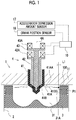
- FIG. 1 is a sectional view of an internal combustion engine 1 related to the present embodiment.
- a cylinder 2 of the internal combustion engine 1 is equipped with a piston 3.
- the internal combustion engine 1 is, for example, a diesel engine that performs compression self-ignition combustion.
- the internal combustion engine 1 is mounted on, for example, a vehicle.
- a cavity 31 that is recessed from a top part of a piston 3 toward the inside of the piston 3 is formed in the piston 3.
- the cavity 31 of the piston 3 is configured so as to make the internal combustion engine perform self-ignition combustion.
- a squish area 100 is formed between the top part of the piston 3 and a cylinder head 11.
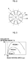
- FIG. 2 is a view of the fuel injection valve 4 as seen from the piston 3 side.
- a plurality of first injection holes 41 A and a plurality of second injection holes 41B are provided at equal angles about a central axis 4A of the fuel injection valve 4 on a tip side of a main body 41 of the fuel injection valve 4.
- the central axis 4A of the fuel injection valve 4 coincides with a central axis of the cylinder 2.
- the second injection holes 41B are formed closer to the tip side of the fuel injection valve 4 and closer to a central axis 4A side of the fuel injection valve 4 than the first injection holes 41 A.
- the first injection holes 41A and the second injection holes 41B are provided by the same numbers, and one of the first injection holes 41 A and one of the second injection holes 41B nearest to this first injection hole 41 A are arranged as a pair of injection holes.
- the first injection hole 41A and the second injection hole 41B that form the pair of injection holes are arranged on the same plane passing through the central axis 4A of the fuel injection valve 4.
- the fuel injection valve 4 is provided with an outer needle 42 that opens and closes the first injection hole 41A, and an inner needle 43 that opens and closes the second injection hole 41B.
- the outer needle 42 is moved forward and backward by an outer needle valve gear 42A
- the inner needle 43 is moved forward and backward by an inner needle valve gear 43A.
- the outer needle valve gear 42A and the inner needle valve gear 43A are equipped with, for example, piezoelectric elements, and the outer needle 42 and the inner needle 43 are separately lifted by separately energizing the piezoelectric elements.
- the outer needle 42 is equivalent to the first needle in the invention
- the inner needle 43 is equivalent to the second needle in the invention.
- the first injection hole 41A and the second injection hole 41B are formed such that a portion of a spray of fuel injected from the first injection hole 41A and a portion of a spray of fuel injected from the second injection hole 41B making a pair with the first injection hole 41A overlap each other at a position with a predetermined distance L1 from a side wall 31A of the cavity 31.
- the predetermined distance L1 is a range that can be said to be the vicinity of the side wall 31A.
- the first injection hole 41A and the second injection hole 41B are formed such that a central axis 41AA of the first injection hole 41A and a central axis 41BB of the second injection hole 41B intersect each other at a point P1 (hereinafter, referred to as an intersection P1) with the predetermined distance L1 from the side wall 31 A of the cavity 31.
- the portion of the spray of the fuel injected from the first injection hole 41A and the portion of the spray of the fuel injected from the second injection hole 41B have only to overlap each other in the vicinity of the side wall 31A of the cavity 31. Therefore, the intersection PI may be on the side wall 31A. That is, the predetermined distance L1 may be set as 0. Additionally, in the present embodiment, the central axis 41AA of the first injection hole 41A and the central axis 41BB of the second injection hole 41B intersect each other at the intersection P1.
- the portion of the spray of the fuel injected from the first injection hole 41 A and the portion the spray of the fuel injected from the second injection hole 41B have only to overlap each other at the position with the predetermined distance L1 from the side wall 31A of the cavity 31, the central axis 41AA of the first injection hole 41A and the central axis 41BB of the second injection hole 41B do not necessarily intersect each other.
- the ECU 10 that is an electronic control unit for controlling the internal combustion engine 1 is provided as an annex in the internal combustion engine 1 configured as described above.
- the ECU 10 controls the internal combustion engine 1 according to the operation conditions of the internal combustion engine 1 or driver's requests.
- An accelerator depression amount sensor 17 that outputs an electrical signal according to an amount by which the driver steps on an accelerator pedal and detects an engine load, and a crank position sensor 18 that detects an engine rotation speed are connected to the ECU 10 via electrical wiring lines, and output signals of these various sensors are input to the ECU 10.
- the outer needle valve gear 42A and the inner needle valve gear 43A are connected to the ECU 10 via electrical wiring lines, and these devices are controlled by the ECU 10. If a command signal is supplied from the ECU 10 to the outer needle valve gear 42A, the outer needle 42 ascends, and thereby, the outer needle 42 moves in a direction in which the first injection hole 41A is opened. On the other hand, if the supply of the command signal from the ECU 10 to the outer needle valve gear 42A is stopped, the outer needle 42 descends, and thereby, the outer needle 42 moves in a direction in which the first injection hole 41A is closed.
- the ECU 10 determines the fuel injection amount and the timing of fuel timing from the fuel injection valve 4 on the basis of the operational state (for example, the engine rotation speed and the accelerator depression amount) of the internal combustion engine 1.
- a relationship between the operational state of the internal combustion engine 1, and the amounts of fuel injection and the timings of fuel injection from the first injection hole 41A and the second injection hole 41B are obtained and mapped in advance by experiment or the like, and are stored in the ECU 10.
- the map of the fuel injection amounts is set such that an air-fuel ratio within a cylinder becomes a target air-fuel ratio, and this target air-fuel ratio is set according to the operational state of the internal combustion engine 1.
- the ECU 10 carries out, for example, main injection, pilot injection, and after-injection, according to the operational state of the internal combustion engine 1.
- the pilot injection is fuel injection performed before the main injection
- the after-injection is fuel injection performed after the main injection.
- FIG. 3 is a view illustrating a relationship between the engine rotation speed and the accelerator depression amount.
- Region 1 is an operating region where the engine rotation speed or the accelerator depression amount is moderate, and for example, the pilot injection and the main injection are carried out in this region.
- Region 2 is an operating region where the engine rotation speed or the accelerator depression amount is comparatively small, and for example, the pilot injection, the main injection, and the after-injection are carried out in this region.
- Region 3 is an operating region where the engine rotation speed or the accelerator depression amount is comparatively large, and for example, the pilot injection and the main injection are carried out in this region.
- FIG. 4 is a view illustrating a relationship between the lift amounts of the outer needle 42 and the inner needle 43 and the crank angle related to the present embodiment.
- FIG. 4 illustrates a case where the pilot injection, the main injection, and the after-injection are carried out in Region 2.
- "Full lifts" are lift amounts in a case where the lift amounts of the outer needle 42 and the inner needle 43 becomes the largest, respectively.
- the inner needle 43 corresponds to the pilot injection, the main injection, and the after-injection, and the outer needle 42 corresponds to only the main injection. That is, although the main injection is carried out from both the first injection hole 41A and the second injection hole 41B, the pilot injection and the after-injection are carried out only from the second injection hole 41B.
- the lift amount of the outer needle 42 starts to increase before a point of time when the lift amount of the inner needle 43 starts to increase in the main injection.
- a time difference of points of time when the lift amounts of the inner needle 43 and the outer needle 42, respectively, in this main injection start to increase is illustrated by T1 in FIG. 4 .
- the time difference T1 is illustrated not as a difference of the crank angle but as a difference of time.
- the time difference T1 in the embodiment is equivalent to a predetermined time or a predetermined main delay time in the invention.
- the main injection from the first injection hole 41A is referred to as a first main injection
- the main injection from the second injection hole 41B is referred to as a second main injection.
- the combustion of fuel related to the main injection starts at a comparatively early timing if the main injection is carried out because the temperature within the cylinder 2 is high. Therefore, the combustion of fuel related to the main injection can be expanded at a comparatively early timing. In this case, since the combustion is expanded when the mixing between fuel and air is still insufficient, fuel is combusted in a state where oxygen runs short in a place where fuel concentration is high. If so, there is a concern that soot may be generated by local oxygen shortage.
- the first injection hole 41A and the second injection hole 41B are formed such that the portion of the spray of fuel injected from the first injection hole 41A and the portion of the spray of fuel injected from the second injection hole 41B making a pair with the first injection hole 41A overlap each other at a position with the predetermined distance L1 from the side wall 31 A of the cavity 31, and fuel injection is carried out from the first injection hole 41A and the second injection hole 41B by providing the time difference T1 related to FIG. 4 at the time of the main injection.
- the pair of injection holes are formed such that a portion of a fuel spray formed by the second main injection and a portion of a fuel spray formed by the first main injection overlap each other, and the time difference T1 is provided by injecting fuel. Therefore, in a place where the fuel sprays overlap each other, the temperature of the fuel spray formed by the first main injection falls due to the evaporation latent heat of the fuel by the second main injection. For this reason, expansion of combustion at a comparatively early timing can be suppressed.
- the fuel spray formed by the second main injection overlaps the fuel spray formed by the first main injection in the middle of evaporation in a place other than the place where combustion is started, the combustion of fuel by second main injection is suppressed due to the evaporation latent heat of the fuel spray formed by the first main injection.
- the fuel spray formed by the first main injection and the fuel spray formed by the second main injection do not overlap each other up to a position where the fuel spray formed by the first main injection starts combustion, both the fuel sprays can be mixed with more air, respectively. Thus, the mixing between fuel and air is promoted.
- both the fuel sprays do not overlap each other up to the position with the predetermined distance L1 from the side wall 31A of the cavity 31, it is possible to suppress a situation in which the particle diameter of fuel becomes large.
- the time until combustion is expanded can be extended, the mixing between fuel by the first main injection and the second main injection, and air can be promoted during that time.
- combustion is expanded in a state where the mixing between fuel and air proceeds, generation of soot can be suppressed.
- FIG. 5 is a view illustrating a relationship between the amount of soot generated, and the time difference T1.
- a reduction effect of soot is seen in 130 ⁇ s or less.
- the discharge amount of soot can be reduced by setting the time difference T1 to, for example, 130 ⁇ s or less.
- the time difference T1 is too short as illustrated in FIG. 5 , the amount of soot can be increased on the contrary. For this reason, an optimum value of the time difference T1 is obtained by experiment or simulation.
- the easiness of combustion of fuel varies according to the operational state of the internal combustion engine 1 and the cetane number of fuel.
- the optimum value of the time difference T1 can vary depending on the operational state of the internal combustion engine 1 and the cetane number of fuel.
- the time difference T1 is obtained in association with the operational state (accelerator depression amount) of the internal combustion engine 1 and the cetane number of fuel.
- FIG. 6 is a view illustrating a relationship between the engine rotation speed and the time difference T1. Since the easiness of combustion of fuel (the easiness of self-ignition) hardly varies even if the engine rotation speed has varied, the time difference T1 is not changed depending on the engine rotation.
- FIG. 7 is a view illustrating a relationship between the accelerator depression amount and the time difference T1. Since the temperature within the cylinder 2 becomes higher as the accelerator depression amount becomes larger, the time from the main injection to the start of combustion can be shortened. Hence, the time difference T1 is made smaller as the accelerator depression amount is larger.
- FIG. 8 is a view illustrating a relationship between the cetane number of fuel and the time difference T1.
- the time difference T1 is made smaller as the cetane number is larger.
- the relationship between the accelerator depression amount and the cetane number, and the time difference T1 is obtained in advance by experiment or simulation, and is stored in the ECU 10. Since it is considered that the value of the cetane number is determined depending on areas, the cetane number of fuel assumed to be supplied depending on areas may be set in advance.
- FIG. 9 is a flowchart illustrating a control flow of fuel injection related to the present embodiment. The flowchart is executed in each cycle of each cylinder 2 by the ECU 10 in Region 2.
- Step S101 the operational state of the internal combustion engine 1 is acquired.
- the ECU 10 acquires the accelerator depression amount obtained on the basis of the output signal of the accelerator depression amount sensor 17, and the engine rotation speed obtained on the basis of the output signal of the crank position sensor 18. These are used when obtaining fuel injection amounts and fuel injection timings.
- Step S102 on the basis of the operational state of the internal combustion engine 1, a pilot injection amount that is a fuel injection amount at the time of the pilot injection, a first main injection amount that is a fuel injection amount at the time of the first main injection, a second main injection amount that is a fuel injection amount at the time of the second main injection, an after-injection amount that is a fuel injection amount at the time of the after-injection are calculated, and a pilot injection timing that is a timing for starting the pilot injection, a first main fuel injection timing that is a timing for starting the first main injection, and an after-injection timing that is a timing for starting the after-injection are calculated.
- Maps or calculation formulas for obtaining the pilot injection amount, the pilot injection timing, the first main injection amount, the first main fuel injection timing, the after-injection amount, and the after-injection timing, respectively, on the basis of the operational state of the internal combustion engine 1 are obtained by experiment or simulation and are stored in advance in the ECU 10.
- the second main fuel injection timing that is the timing for starting the second main injection is calculated by adding the aforementioned time difference T1 to the first main fuel injection timing.
- the first main injection amount and the second main injection amount may be the same amounts or may be different amounts. Since these maps or calculation formulas change depending on the operating regions of the internal combustion engine 1, maps or calculation formulas corresponding to Region 2 are used in this Step S102.
- Step S103 it is determined whether or not it is the pilot injection timing. In a case where the determination is positive in Step S103, the processing proceeds to Step S104 where the pilot injection is carried out. Since the pilot injection is carried out from the second injection hole 41B, the ECU 10 gives a command signal to the inner needle valve gear 43A for a time according to the pilot injection amount. On the other hand, in a case where the determination is negative in Step S103, Step S103 is executed again.
- Step S105 it is determined whether or not there is the first main fuel injection timing. In a case where the determination is positive in Step S105, the processing proceeds to Step S106 where the first main injection is carried out. Since the first main injection is carried out from the first injection hole 41 A, the ECU 10 gives a command signal to the outer needle valve gear 42A for a time according to the first main injection amount. On the other hand, in a case where the determination is negative in Step S105, Step S105 is executed again.
- Step S107 it is determined whether or not there is the second main fuel injection timing. In a case where the determination is positive in Step S107, the processing proceeds to Step S108 where the second main injection is carried out. Since the second main injection is carried out from the second injection hole 41B, the ECU 10 gives a command signal to the inner needle valve gear 43A for a time according to the second main injection amount. On the other hand, in a case where the determination is negative in Step S107, Step S107 is executed again.
- Step S109 it is determined whether or not there is the after-injection timing.
- the after-injection timing is obtained in advance by experiment or simulation in association with the operational state of the internal combustion engine 1, and is stored in the ECU.
- the processing proceeds to Step S110 where the after-injection is carried out. Since the after-injection is carried out from the second injection hole 41B, the ECU 10 gives a command signal to the inner needle valve gear 43A for a time according to the after-injection amount.
- Step S109 is executed again.
- the pilot injection is performed from the second injection hole 41B. Instead of this, however, the pilot injection may be carried out from the first injection hole 41A.
- the after-injection is performed from the second injection hole 41B. Instead of this, however, the after-injection may be carried out from the first injection hole 41A.
- the first main injection is performed before the second main injection. However, the second main injection may be performed before the first main injection by changing the order. However, by changing an injection hole for performing the main injection first to an injection hole for performing the pilot injection as illustrated in FIG. 4 , reception of the influence of pulsation of fuel generated at the time of the pilot injection at the time of the main injection can be suppressed. Therefore, this is even better.
- expansion of combustion at an early stage can be suppressed by shifting the first main injection and the second main injection such that the portion of the fuel spray of the first main injection and the portion of the fuel spray of the second main injection overlap each other at the position apart by the predetermined distance L1 from the side wall 31A of the cavity 31. Therefore, combustion can be expanded after the mixing between fuel and air has proceeded. Accordingly, generation of soot can be suppressed.
- the after-injection is performed in a divided manner from the first injection hole 41A and the second injection hole 41B. Additionally, the main injection is performed only from the second injection hole 41B. Since the other devices are the same as those of Embodiment 1, the description thereof is omitted.
- an after-injection from the first injection hole 41A is referred to as a first after-injection
- an after-injection from the second injection hole 41B is referred to as a second after-injection.
- a timing for starting the after-injection from the first injection hole 41A is referred to as a first after-injection timing
- a timing for starting the after-injection from the second injection hole 41B is referred to as a second after-injection timing.
- a fuel injection amount at the time of the first after-injection is referred to as a first after-injection amount
- a fuel injection amount at the time of the second after-injection is referred to as a second after-injection amount.
- a time difference T2 is provided between the first after-injection timing and the second after-injection timing. That is, a time difference of points of time when the lift amounts of the inner needle 43 and the outer needle 42, respectively, in the after-injection start to increase is defined as T2.
- the time difference T2 in the embodiment is equivalent to a predetermined time or a predetermined after-delay time in the invention. Since the temperature within the cavity 31 is rising due to the combustion of fuel by the main injection at the time of the after-injection, the fuel based on the after-injection is more easily combusted than the fuel based on the main injection.
- the time difference T2 is set in light of this point.
- FIG. 10 is a view illustrating a relationship between the lift amounts of the outer needle 42 and the inner needle 43 and, the crank angle related to the present embodiment.
- the lift amount of the inner needle 43 increases in response to the pilot injection, the main injection, and the second after-injection
- the lift amount of the outer needle 42 increases in response to the first after-injection. That is, although the after-injection is carried out from both the first injection hole 41 A and the second injection hole 41B, the pilot injection and the main injection are carried out only from the second injection hole 41B.
- the lift amount of the outer needle 42 starts to increase before the lift amount of the inner needle 43 starts to increase in the after-injection.
- a time difference of points of time when the lift amounts of the inner needle 43 and the outer needle 42, respectively, in the after-injection start to increase is T2.
- FIG. 11 is a flowchart illustrating a control flow of fuel injection related to Embodiment 2.
- the flowchart is executed in each cycle of each cylinder 2 by the ECU 10 in Region 2. Steps where the same processing as that of the flowchart illustrated in FIG. 9 is performed will be denoted by the same reference signs, and the description thereof will be omitted.
- Step S201 the pilot injection amount, the pilot injection timing, the main injection amount, the main fuel injection timing, the first after-injection amount, the first after-injection timing, and the second after-injection amount are calculated on the basis of the operational state of the internal combustion engine 1. Maps or calculation formulas for obtaining the pilot injection amount, the pilot injection timing, the main injection amount, the main fuel injection timing, the first after-injection amount, the first after-injection timing, and the second after-injection amount, respectively, on the basis of the operational state of the internal combustion engine 1 are obtained in advance by experiment or simulation and are stored in the ECU 10.
- the second after-injection timing is calculated by adding the aforementioned time difference T2 to the first after-injection timing.
- the first after-injection amount and the second after-injection amount may be the same amounts or may be different amounts.
- Step S202 it is determined whether or not there is the main injection timing. In a case where the determination is positive in Step S202, the processing proceeds to Step S203 where the main injection is carried out. Since the main injection is carried out from the second injection hole 41B, the ECU 10 gives a command signal to the inner needle valve gear 43A for a time according to the main injection amount. On the other hand, in a case where the determination is negative in Step S202, Step S202 is executed again.
- Step S204 it is determined whether or not there is the first after-injection timing. In a case where the determination is positive in Step S204, the processing proceeds to Step S205 where the first after-injection is carried out. Since the first after-injection is carried out from the first injection hole 41A, the ECU 10 gives a command signal to the outer needle valve gear 42A for a time according to the first after-injection amount. On the other hand, in a case where the determination is negative in Step S204, Step S204 is executed again.
- Step S206 it is determined whether or not there is the second after-injection timing. In a case where the determination is positive in Step S206, the processing proceeds to Step S207 where the second after-injection is carried out. Since the second after-injection is carried out from the second injection hole 41B, the ECU 10 gives a command signal to the inner needle valve gear 43A for a time according to the second after-injection amount. On the other hand, in a case where the determination is negative in Step S206, Step S206 is executed again.
- the pilot injection is performed from the second injection hole 41B. Instead of this, however, the pilot injection may be carried out from the first injection hole 41A.
- the main injection is performed from the second injection hole 41B. Instead of this, however, the main injection may be carried out from the first injection hole 41A.
- the first after-injection is performed before the second after-injection. However, the second after-injection may be performed before the first after-injection by changing the order. However, by changing an injection hole for performing the after-injection first to an injection hole for performing the main injection as illustrated in FIG. 10 , the influence of pulsation of fuel generated at the time of the main injection at the time of the after-injection can be suppressed. Therefore, this is even better.
- expansion of combustion at an early stage can be suppressed by shifting the first after-injection and the second after-injection such that the portion of the fuel spray of the first after-injection and the portion of the fuel spray of the second after-injection overlap each other at the position apart by the predetermined distance L1 from the side wall 31A of the cavity 31. Therefore, combustion can be expanded after the mixing between fuel and air has proceeded. Accordingly, generation of soot can be suppressed.
- the main injection and the after-injection are performed in a divided manner from the first injection hole 41A and the second injection hole 41B. Since the other devices are the same as those of Embodiment 1, the description thereof is omitted.
- FIG. 12 is a view illustrating a relationship between the lift amounts of the outer needle 42 and the inner needle 43 and, the crank angle related to the present embodiment.
- the lift amount of the inner needle 43 increases in response to the pilot injection, the second main injection, and the second after-injection
- the lift amount of the outer needle 42 increases in response to the first main injection and the first after-injection. That is, although the main injection and the after-injection are carried out from both the first injection hole 41A and the second injection hole 41B, the pilot injection is carried out only from the second injection hole 41B.
- the lift amount of the outer needle 42 starts to increase before the lift amount of the inner needle 43 starts to increase in the main injection and the after-injection.
- a time difference of points of time when the lift amounts of the inner needle 43 and the outer needle 42, respectively, in the main injection start to increase is T1
- a time difference of points of time when of the lift amounts of the inner needle 43 and the outer needle 42, respectively, in the after-injection start to increase is T2.
- the pilot injection is performed from the second injection hole 41B.
- the pilot injection may be carried out from the first injection hole 41A.
- the first main injection is performed before the second main injection.
- the second main injection may be performed before the first main injection by changing the order.
- the first after-injection is performed before the second after-injection.
- the second after-injection may be performed before the first after-injection by changing the order.
- FIG. 13 is a view illustrating a relationship between the lift amounts of the outer needle 42 and the inner needle 43 and, the crank angle related to the present embodiment. A time difference of points of time when the lift amounts of the inner needle 43 and the outer needle 42, respectively, in this main injection start to increase is illustrated by T3 in FIG. 13 .
- the time difference T1 in Region 2 and the time difference T3 in Region 3 are set to different values. In this way, even in a case where the after-injection is not carried out, expansion of combustion at an early stage can be suppressed by shifting the first main injection and the second main injection. Therefore, combustion can be made after the mixing between fuel and air has proceeded. Accordingly, generation of soot can be suppressed.
- the time difference T3 in the embodiment is equivalent to a predetermined time or a predetermined main delay time in the invention.
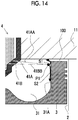
- the amounts of fuel after being injected from the first injection hole 41A and the second injection hole 41B and overlap each other is a predetermined ratio
- the first injection hole 41A and the second injection hole 41B are formed so as to be divided into a bottom part side (that is, a bottom part side of the cavity 31) of the piston 3 and a top part side (that is, a cylinder head 11 side) of the piston 3.
- FIG. 14 is a view illustrating fuel sprays divided in a predetermined ratio.
- a fuel spray that faces the top part side of the piston 3 is illustrated by S1
- a fuel spray that faces the bottom part side of the piston 3 is illustrated by S2.
- the squish area 100 is formed between a top part surface of the piston 3, and the cylinder head 11. Since the volume of the squish area 100 becomes small with the ascent of the piston 3, an airflow is generated from the squish area 100 toward the central axis 4A side.
- the fuel injected from the first injection hole 41A and the second injection hole 41B is stirred by the airflow from the squish area 100, the mixing between air and fuel is promoted. That is, after the expansion of combustion is suppressed at an intersection PI and before the combustion is expanded, division into the fuel spray S1 that faces the top part side of the piston 3, and the fuel spray S2 that faces the bottom part side of the piston 3 is made. Also, since combustion of the fuel spray S1 that faces the top part side of the piston 3 is expanded after the mixing between fuel and air is further promoted by the airflow from the squish area 100, the amount of generation of soot can be reduced.
- the predetermined ratio can be obtained as an optimum value by experiment or simulation, and is, for example, 1 to 1.
Landscapes
- Engineering & Computer Science (AREA)
- Chemical & Material Sciences (AREA)
- Combustion & Propulsion (AREA)
- Mechanical Engineering (AREA)
- General Engineering & Computer Science (AREA)
- Dispersion Chemistry (AREA)
- Electrical Control Of Air Or Fuel Supplied To Internal-Combustion Engine (AREA)
- Fuel-Injection Apparatus (AREA)
Applications Claiming Priority (1)
| Application Number | Priority Date | Filing Date | Title |
|---|---|---|---|
| JP2016114546A JP6436133B2 (ja) | 2016-06-08 | 2016-06-08 | 内燃機関 |
Publications (2)
| Publication Number | Publication Date |
|---|---|
| EP3255268A1 true EP3255268A1 (fr) | 2017-12-13 |
| EP3255268B1 EP3255268B1 (fr) | 2020-05-06 |
Family
ID=59030887
Family Applications (1)
| Application Number | Title | Priority Date | Filing Date |
|---|---|---|---|
| EP17174998.9A Active EP3255268B1 (fr) | 2016-06-08 | 2017-06-08 | Moteur à combustion interne |
Country Status (3)
| Country | Link |
|---|---|
| US (1) | US10202931B2 (fr) |
| EP (1) | EP3255268B1 (fr) |
| JP (1) | JP6436133B2 (fr) |
Families Citing this family (6)
| Publication number | Priority date | Publication date | Assignee | Title |
|---|---|---|---|---|
| JP6439753B2 (ja) * | 2016-06-08 | 2018-12-19 | トヨタ自動車株式会社 | 内燃機関 |
| JP7067316B2 (ja) * | 2018-06-28 | 2022-05-16 | マツダ株式会社 | ディーゼルエンジンの燃料噴射制御装置 |
| JP7047751B2 (ja) * | 2018-12-25 | 2022-04-05 | マツダ株式会社 | 圧縮着火エンジン |
| JP7124733B2 (ja) | 2019-01-29 | 2022-08-24 | マツダ株式会社 | 圧縮着火エンジンの制御装置 |
| JP7124734B2 (ja) | 2019-01-29 | 2022-08-24 | マツダ株式会社 | 圧縮着火エンジンの制御装置 |
| JP7124732B2 (ja) * | 2019-01-29 | 2022-08-24 | マツダ株式会社 | 圧縮着火エンジンの制御装置 |
Citations (5)
| Publication number | Priority date | Publication date | Assignee | Title |
|---|---|---|---|---|
| JPS61218772A (ja) * | 1985-03-25 | 1986-09-29 | Mitsui Eng & Shipbuild Co Ltd | デイ−ゼル機関用燃料噴射装置 |
| JPH09236067A (ja) * | 1996-02-28 | 1997-09-09 | Isuzu Motors Ltd | 燃料噴射ノズル |
| JP2000064928A (ja) | 1998-01-06 | 2000-03-03 | Mitsubishi Automob Eng Co Ltd | 燃料噴射ノズル |
| WO2003078824A1 (fr) * | 2002-03-13 | 2003-09-25 | Robert Bosch Gmbh | Soupape d'injection de carburant pour moteurs a combustion interne |
| WO2006104232A2 (fr) * | 2005-03-28 | 2006-10-05 | Toyota Jidosha Kabushiki Kaisha | Systeme d'injection de carburant de moteur a combustion interne |
Family Cites Families (22)
| Publication number | Priority date | Publication date | Assignee | Title |
|---|---|---|---|---|
| JPS59147864A (ja) | 1983-02-12 | 1984-08-24 | Toyota Motor Corp | デイ−ゼルエンジンの燃料噴射弁 |
| JPH08254123A (ja) * | 1995-03-20 | 1996-10-01 | Mitsubishi Motors Corp | 内燃機関の燃焼室 |
| DE19858345A1 (de) * | 1998-01-06 | 1999-07-08 | Mitsubishi Motors Corp | Brennstoffeinspritzdüse |
| GB9913314D0 (en) * | 1999-06-09 | 1999-08-11 | Lucas Ind Plc | Fuel injector |
| GB9914644D0 (en) * | 1999-06-24 | 1999-08-25 | Lucas Ind Plc | Fuel injector |
| JP2003286879A (ja) * | 2002-03-27 | 2003-10-10 | Mazda Motor Corp | ディーゼルエンジンの燃焼制御装置 |
| JP4075511B2 (ja) | 2002-08-07 | 2008-04-16 | トヨタ自動車株式会社 | 内燃機関の燃料噴射装置 |
| DE10354878A1 (de) * | 2003-11-24 | 2005-06-09 | Robert Bosch Gmbh | Kraftstoff-Einspritzvorrichtung, insbesondere für eine Brennkraftmaschine mit Kraftstoff-Direkteinspritzung, sowie Verfahren zu ihrer Herstellung |
| EP1645749A1 (fr) | 2004-09-17 | 2006-04-12 | Delphi Technologies, Inc. | Injecteur de combustible et procédé de fabrication d'un injecteur de combustible |
| DE602004008630T2 (de) * | 2004-10-01 | 2008-06-12 | Delphi Technologies, Inc., Troy | Einspritzdüse |
| JP2007231852A (ja) * | 2006-03-01 | 2007-09-13 | Toyota Motor Corp | 燃料噴射装置 |
| JP2008064073A (ja) * | 2006-09-11 | 2008-03-21 | Toyota Motor Corp | 燃料噴射装置 |
| US7895986B2 (en) * | 2007-08-14 | 2011-03-01 | Mazda Motor Corporation | Diesel engine and fuel injection nozzle therefor |
| JP2010223166A (ja) | 2009-03-25 | 2010-10-07 | Nippon Soken Inc | 内燃機関の燃料噴射制御装置 |
| JP5045773B2 (ja) | 2010-03-12 | 2012-10-10 | トヨタ自動車株式会社 | 燃料噴射制御装置 |
| JP2012184747A (ja) * | 2011-03-08 | 2012-09-27 | Fuji Heavy Ind Ltd | ディーゼルエンジン |
| JP2013024197A (ja) * | 2011-07-25 | 2013-02-04 | Nippon Soken Inc | 内燃機関の燃料噴射制御装置 |
| JP2013204455A (ja) | 2012-03-27 | 2013-10-07 | Toyota Motor Corp | 燃料噴射弁 |
| JP5991251B2 (ja) | 2013-03-28 | 2016-09-14 | マツダ株式会社 | ディーゼルエンジンの燃料噴射制御装置 |
| US9562505B2 (en) * | 2013-06-11 | 2017-02-07 | Cummins Inc. | System and method for control of fuel injector spray |
| JP2015169130A (ja) * | 2014-03-07 | 2015-09-28 | 株式会社日本自動車部品総合研究所 | 燃料噴射弁 |
| JP6439753B2 (ja) * | 2016-06-08 | 2018-12-19 | トヨタ自動車株式会社 | 内燃機関 |
-
2016
- 2016-06-08 JP JP2016114546A patent/JP6436133B2/ja active Active
-
2017
- 2017-06-08 EP EP17174998.9A patent/EP3255268B1/fr active Active
- 2017-06-08 US US15/617,145 patent/US10202931B2/en active Active
Patent Citations (5)
| Publication number | Priority date | Publication date | Assignee | Title |
|---|---|---|---|---|
| JPS61218772A (ja) * | 1985-03-25 | 1986-09-29 | Mitsui Eng & Shipbuild Co Ltd | デイ−ゼル機関用燃料噴射装置 |
| JPH09236067A (ja) * | 1996-02-28 | 1997-09-09 | Isuzu Motors Ltd | 燃料噴射ノズル |
| JP2000064928A (ja) | 1998-01-06 | 2000-03-03 | Mitsubishi Automob Eng Co Ltd | 燃料噴射ノズル |
| WO2003078824A1 (fr) * | 2002-03-13 | 2003-09-25 | Robert Bosch Gmbh | Soupape d'injection de carburant pour moteurs a combustion interne |
| WO2006104232A2 (fr) * | 2005-03-28 | 2006-10-05 | Toyota Jidosha Kabushiki Kaisha | Systeme d'injection de carburant de moteur a combustion interne |
Also Published As
| Publication number | Publication date |
|---|---|
| US20170356384A1 (en) | 2017-12-14 |
| EP3255268B1 (fr) | 2020-05-06 |
| JP2017218992A (ja) | 2017-12-14 |
| US10202931B2 (en) | 2019-02-12 |
| JP6436133B2 (ja) | 2018-12-12 |
Similar Documents
| Publication | Publication Date | Title |
|---|---|---|
| EP3255268B1 (fr) | Moteur à combustion interne | |
| JP6439753B2 (ja) | 内燃機関 | |
| JP3931900B2 (ja) | ディーゼルエンジンの制御装置 | |
| JP6098613B2 (ja) | 内燃機関 | |
| JP4161974B2 (ja) | ディーゼル式内燃機関の制御装置 | |
| JP2009500566A (ja) | 内燃機関における作動モード間の移行方法 | |
| JP6172375B2 (ja) | 直噴ガソリンエンジンの制御装置 | |
| JP2007107436A (ja) | 筒内直接噴射式エンジンおよびその制御装置並びにインジェクタ | |
| JP2016223411A (ja) | エンジンの制御装置 | |
| WO2008133355A1 (fr) | Système d'injection de carburant de moteur à combustion interne à allumage par compression | |
| JP2016223412A (ja) | エンジンの制御装置 | |
| JP4743183B2 (ja) | 燃料噴射制御装置 | |
| US10378476B2 (en) | Internal combustion engine | |
| US10309338B2 (en) | Fuel injection control device for direct-injection engine | |
| WO2015036825A1 (fr) | Dispositif de commande d'un moteur à combustion interne | |
| JP2014141918A (ja) | 火花点火式多気筒エンジンの始動装置 | |
| US20190040814A1 (en) | Fuel Injection Valve Control Device | |
| EP2405120A1 (fr) | Dispositif de commande de combustion pour moteur à combustion interne | |
| JP2002317734A (ja) | ディーゼルエンジンの燃料噴射装置 | |
| JP4258396B2 (ja) | 予混合圧縮着火内燃機関 | |
| JPH1182029A (ja) | 内燃機関の成層燃焼方法 | |
| JP2011085103A (ja) | 内燃機関の燃料噴射システム | |
| JPWO2003029635A1 (ja) | 内燃機関の成層混合気形成装置及び方法 | |
| JP2012112246A (ja) | 内燃機関の制御装置 | |
| JP2009185689A (ja) | 圧縮着火エンジン及びその制御方法 |
Legal Events
| Date | Code | Title | Description |
|---|---|---|---|
| PUAI | Public reference made under article 153(3) epc to a published international application that has entered the european phase |
Free format text: ORIGINAL CODE: 0009012 |
|
| STAA | Information on the status of an ep patent application or granted ep patent |
Free format text: STATUS: REQUEST FOR EXAMINATION WAS MADE |
|
| 17P | Request for examination filed |
Effective date: 20170608 |
|
| AK | Designated contracting states |
Kind code of ref document: A1 Designated state(s): AL AT BE BG CH CY CZ DE DK EE ES FI FR GB GR HR HU IE IS IT LI LT LU LV MC MK MT NL NO PL PT RO RS SE SI SK SM TR |
|
| AX | Request for extension of the european patent |
Extension state: BA ME |
|
| RIC1 | Information provided on ipc code assigned before grant |
Ipc: F02M 45/08 20060101ALI20191118BHEP Ipc: F02B 23/06 20060101ALI20191118BHEP Ipc: F02M 61/18 20060101ALI20191118BHEP Ipc: F02D 41/40 20060101AFI20191118BHEP |
|
| GRAP | Despatch of communication of intention to grant a patent |
Free format text: ORIGINAL CODE: EPIDOSNIGR1 |
|
| STAA | Information on the status of an ep patent application or granted ep patent |
Free format text: STATUS: GRANT OF PATENT IS INTENDED |
|
| INTG | Intention to grant announced |
Effective date: 20200110 |
|
| GRAS | Grant fee paid |
Free format text: ORIGINAL CODE: EPIDOSNIGR3 |
|
| GRAA | (expected) grant |
Free format text: ORIGINAL CODE: 0009210 |
|
| STAA | Information on the status of an ep patent application or granted ep patent |
Free format text: STATUS: THE PATENT HAS BEEN GRANTED |
|
| AK | Designated contracting states |
Kind code of ref document: B1 Designated state(s): AL AT BE BG CH CY CZ DE DK EE ES FI FR GB GR HR HU IE IS IT LI LT LU LV MC MK MT NL NO PL PT RO RS SE SI SK SM TR |
|
| RAP1 | Party data changed (applicant data changed or rights of an application transferred) |
Owner name: TOYOTA JIDOSHA KABUSHIKI KAISHA |
|
| REG | Reference to a national code |
Ref country code: GB Ref legal event code: FG4D |
|
| RIN1 | Information on inventor provided before grant (corrected) |
Inventor name: ITO, HISAKI Inventor name: TAKADA, NORIYUKI |
|
| REG | Reference to a national code |
Ref country code: CH Ref legal event code: EP Ref country code: AT Ref legal event code: REF Ref document number: 1267121 Country of ref document: AT Kind code of ref document: T Effective date: 20200515 |
|
| REG | Reference to a national code |
Ref country code: IE Ref legal event code: FG4D |
|
| REG | Reference to a national code |
Ref country code: DE Ref legal event code: R096 Ref document number: 602017016017 Country of ref document: DE |
|
| REG | Reference to a national code |
Ref country code: LT Ref legal event code: MG4D |
|
| REG | Reference to a national code |
Ref country code: NL Ref legal event code: MP Effective date: 20200506 |
|
| PG25 | Lapsed in a contracting state [announced via postgrant information from national office to epo] |
Ref country code: SE Free format text: LAPSE BECAUSE OF FAILURE TO SUBMIT A TRANSLATION OF THE DESCRIPTION OR TO PAY THE FEE WITHIN THE PRESCRIBED TIME-LIMIT Effective date: 20200506 Ref country code: LT Free format text: LAPSE BECAUSE OF FAILURE TO SUBMIT A TRANSLATION OF THE DESCRIPTION OR TO PAY THE FEE WITHIN THE PRESCRIBED TIME-LIMIT Effective date: 20200506 Ref country code: IS Free format text: LAPSE BECAUSE OF FAILURE TO SUBMIT A TRANSLATION OF THE DESCRIPTION OR TO PAY THE FEE WITHIN THE PRESCRIBED TIME-LIMIT Effective date: 20200906 Ref country code: PT Free format text: LAPSE BECAUSE OF FAILURE TO SUBMIT A TRANSLATION OF THE DESCRIPTION OR TO PAY THE FEE WITHIN THE PRESCRIBED TIME-LIMIT Effective date: 20200907 Ref country code: FI Free format text: LAPSE BECAUSE OF FAILURE TO SUBMIT A TRANSLATION OF THE DESCRIPTION OR TO PAY THE FEE WITHIN THE PRESCRIBED TIME-LIMIT Effective date: 20200506 Ref country code: GR Free format text: LAPSE BECAUSE OF FAILURE TO SUBMIT A TRANSLATION OF THE DESCRIPTION OR TO PAY THE FEE WITHIN THE PRESCRIBED TIME-LIMIT Effective date: 20200807 Ref country code: NO Free format text: LAPSE BECAUSE OF FAILURE TO SUBMIT A TRANSLATION OF THE DESCRIPTION OR TO PAY THE FEE WITHIN THE PRESCRIBED TIME-LIMIT Effective date: 20200806 |
|
| PG25 | Lapsed in a contracting state [announced via postgrant information from national office to epo] |
Ref country code: LV Free format text: LAPSE BECAUSE OF FAILURE TO SUBMIT A TRANSLATION OF THE DESCRIPTION OR TO PAY THE FEE WITHIN THE PRESCRIBED TIME-LIMIT Effective date: 20200506 Ref country code: RS Free format text: LAPSE BECAUSE OF FAILURE TO SUBMIT A TRANSLATION OF THE DESCRIPTION OR TO PAY THE FEE WITHIN THE PRESCRIBED TIME-LIMIT Effective date: 20200506 Ref country code: BG Free format text: LAPSE BECAUSE OF FAILURE TO SUBMIT A TRANSLATION OF THE DESCRIPTION OR TO PAY THE FEE WITHIN THE PRESCRIBED TIME-LIMIT Effective date: 20200806 Ref country code: HR Free format text: LAPSE BECAUSE OF FAILURE TO SUBMIT A TRANSLATION OF THE DESCRIPTION OR TO PAY THE FEE WITHIN THE PRESCRIBED TIME-LIMIT Effective date: 20200506 |
|
| REG | Reference to a national code |
Ref country code: AT Ref legal event code: MK05 Ref document number: 1267121 Country of ref document: AT Kind code of ref document: T Effective date: 20200506 |
|
| PG25 | Lapsed in a contracting state [announced via postgrant information from national office to epo] |
Ref country code: NL Free format text: LAPSE BECAUSE OF FAILURE TO SUBMIT A TRANSLATION OF THE DESCRIPTION OR TO PAY THE FEE WITHIN THE PRESCRIBED TIME-LIMIT Effective date: 20200506 Ref country code: AL Free format text: LAPSE BECAUSE OF FAILURE TO SUBMIT A TRANSLATION OF THE DESCRIPTION OR TO PAY THE FEE WITHIN THE PRESCRIBED TIME-LIMIT Effective date: 20200506 |
|
| PG25 | Lapsed in a contracting state [announced via postgrant information from national office to epo] |
Ref country code: CZ Free format text: LAPSE BECAUSE OF FAILURE TO SUBMIT A TRANSLATION OF THE DESCRIPTION OR TO PAY THE FEE WITHIN THE PRESCRIBED TIME-LIMIT Effective date: 20200506 Ref country code: RO Free format text: LAPSE BECAUSE OF FAILURE TO SUBMIT A TRANSLATION OF THE DESCRIPTION OR TO PAY THE FEE WITHIN THE PRESCRIBED TIME-LIMIT Effective date: 20200506 Ref country code: IT Free format text: LAPSE BECAUSE OF FAILURE TO SUBMIT A TRANSLATION OF THE DESCRIPTION OR TO PAY THE FEE WITHIN THE PRESCRIBED TIME-LIMIT Effective date: 20200506 Ref country code: SM Free format text: LAPSE BECAUSE OF FAILURE TO SUBMIT A TRANSLATION OF THE DESCRIPTION OR TO PAY THE FEE WITHIN THE PRESCRIBED TIME-LIMIT Effective date: 20200506 Ref country code: EE Free format text: LAPSE BECAUSE OF FAILURE TO SUBMIT A TRANSLATION OF THE DESCRIPTION OR TO PAY THE FEE WITHIN THE PRESCRIBED TIME-LIMIT Effective date: 20200506 Ref country code: DK Free format text: LAPSE BECAUSE OF FAILURE TO SUBMIT A TRANSLATION OF THE DESCRIPTION OR TO PAY THE FEE WITHIN THE PRESCRIBED TIME-LIMIT Effective date: 20200506 Ref country code: AT Free format text: LAPSE BECAUSE OF FAILURE TO SUBMIT A TRANSLATION OF THE DESCRIPTION OR TO PAY THE FEE WITHIN THE PRESCRIBED TIME-LIMIT Effective date: 20200506 Ref country code: ES Free format text: LAPSE BECAUSE OF FAILURE TO SUBMIT A TRANSLATION OF THE DESCRIPTION OR TO PAY THE FEE WITHIN THE PRESCRIBED TIME-LIMIT Effective date: 20200506 |
|
| REG | Reference to a national code |
Ref country code: CH Ref legal event code: PL |
|
| REG | Reference to a national code |
Ref country code: DE Ref legal event code: R097 Ref document number: 602017016017 Country of ref document: DE |
|
| PG25 | Lapsed in a contracting state [announced via postgrant information from national office to epo] |
Ref country code: SK Free format text: LAPSE BECAUSE OF FAILURE TO SUBMIT A TRANSLATION OF THE DESCRIPTION OR TO PAY THE FEE WITHIN THE PRESCRIBED TIME-LIMIT Effective date: 20200506 Ref country code: MC Free format text: LAPSE BECAUSE OF FAILURE TO SUBMIT A TRANSLATION OF THE DESCRIPTION OR TO PAY THE FEE WITHIN THE PRESCRIBED TIME-LIMIT Effective date: 20200506 Ref country code: PL Free format text: LAPSE BECAUSE OF FAILURE TO SUBMIT A TRANSLATION OF THE DESCRIPTION OR TO PAY THE FEE WITHIN THE PRESCRIBED TIME-LIMIT Effective date: 20200506 |
|
| PLBE | No opposition filed within time limit |
Free format text: ORIGINAL CODE: 0009261 |
|
| STAA | Information on the status of an ep patent application or granted ep patent |
Free format text: STATUS: NO OPPOSITION FILED WITHIN TIME LIMIT |
|
| PG25 | Lapsed in a contracting state [announced via postgrant information from national office to epo] |
Ref country code: LU Free format text: LAPSE BECAUSE OF NON-PAYMENT OF DUE FEES Effective date: 20200608 |
|
| 26N | No opposition filed |
Effective date: 20210209 |
|
| REG | Reference to a national code |
Ref country code: BE Ref legal event code: MM Effective date: 20200630 |
|
| PG25 | Lapsed in a contracting state [announced via postgrant information from national office to epo] |
Ref country code: LI Free format text: LAPSE BECAUSE OF NON-PAYMENT OF DUE FEES Effective date: 20200630 Ref country code: CH Free format text: LAPSE BECAUSE OF NON-PAYMENT OF DUE FEES Effective date: 20200630 Ref country code: IE Free format text: LAPSE BECAUSE OF NON-PAYMENT OF DUE FEES Effective date: 20200608 |
|
| PG25 | Lapsed in a contracting state [announced via postgrant information from national office to epo] |
Ref country code: BE Free format text: LAPSE BECAUSE OF NON-PAYMENT OF DUE FEES Effective date: 20200630 Ref country code: SI Free format text: LAPSE BECAUSE OF FAILURE TO SUBMIT A TRANSLATION OF THE DESCRIPTION OR TO PAY THE FEE WITHIN THE PRESCRIBED TIME-LIMIT Effective date: 20200506 |
|
| GBPC | Gb: european patent ceased through non-payment of renewal fee |
Effective date: 20210608 |
|
| PG25 | Lapsed in a contracting state [announced via postgrant information from national office to epo] |
Ref country code: GB Free format text: LAPSE BECAUSE OF NON-PAYMENT OF DUE FEES Effective date: 20210608 |
|
| PG25 | Lapsed in a contracting state [announced via postgrant information from national office to epo] |
Ref country code: TR Free format text: LAPSE BECAUSE OF FAILURE TO SUBMIT A TRANSLATION OF THE DESCRIPTION OR TO PAY THE FEE WITHIN THE PRESCRIBED TIME-LIMIT Effective date: 20200506 Ref country code: MT Free format text: LAPSE BECAUSE OF FAILURE TO SUBMIT A TRANSLATION OF THE DESCRIPTION OR TO PAY THE FEE WITHIN THE PRESCRIBED TIME-LIMIT Effective date: 20200506 Ref country code: CY Free format text: LAPSE BECAUSE OF FAILURE TO SUBMIT A TRANSLATION OF THE DESCRIPTION OR TO PAY THE FEE WITHIN THE PRESCRIBED TIME-LIMIT Effective date: 20200506 |
|
| PG25 | Lapsed in a contracting state [announced via postgrant information from national office to epo] |
Ref country code: MK Free format text: LAPSE BECAUSE OF FAILURE TO SUBMIT A TRANSLATION OF THE DESCRIPTION OR TO PAY THE FEE WITHIN THE PRESCRIBED TIME-LIMIT Effective date: 20200506 |
|
| PGFP | Annual fee paid to national office [announced via postgrant information from national office to epo] |
Ref country code: FR Payment date: 20220408 Year of fee payment: 6 Ref country code: DE Payment date: 20220414 Year of fee payment: 6 |
|
| P01 | Opt-out of the competence of the unified patent court (upc) registered |
Effective date: 20230427 |
|
| REG | Reference to a national code |
Ref country code: DE Ref legal event code: R119 Ref document number: 602017016017 Country of ref document: DE |
|
| PG25 | Lapsed in a contracting state [announced via postgrant information from national office to epo] |
Ref country code: DE Free format text: LAPSE BECAUSE OF NON-PAYMENT OF DUE FEES Effective date: 20240103 |