EP3250002B1 - Haushalts-gargerät - Google Patents
Haushalts-gargerät Download PDFInfo
- Publication number
- EP3250002B1 EP3250002B1 EP17172025.3A EP17172025A EP3250002B1 EP 3250002 B1 EP3250002 B1 EP 3250002B1 EP 17172025 A EP17172025 A EP 17172025A EP 3250002 B1 EP3250002 B1 EP 3250002B1
- Authority
- EP
- European Patent Office
- Prior art keywords
- operating mode
- switch
- heating
- relay
- series
- Prior art date
- Legal status (The legal status is an assumption and is not a legal conclusion. Google has not performed a legal analysis and makes no representation as to the accuracy of the status listed.)
- Active
Links
Images

Classifications
-
- H—ELECTRICITY
- H05—ELECTRIC TECHNIQUES NOT OTHERWISE PROVIDED FOR
- H05B—ELECTRIC HEATING; ELECTRIC LIGHT SOURCES NOT OTHERWISE PROVIDED FOR; CIRCUIT ARRANGEMENTS FOR ELECTRIC LIGHT SOURCES, IN GENERAL
- H05B1/00—Details of electric heating devices
- H05B1/02—Automatic switching arrangements specially adapted to apparatus ; Control of heating devices
- H05B1/0227—Applications
- H05B1/0252—Domestic applications
- H05B1/0258—For cooking
- H05B1/0261—For cooking of food
- H05B1/0263—Ovens
-
- F—MECHANICAL ENGINEERING; LIGHTING; HEATING; WEAPONS; BLASTING
- F24—HEATING; RANGES; VENTILATING
- F24C—DOMESTIC STOVES OR RANGES ; DETAILS OF DOMESTIC STOVES OR RANGES, OF GENERAL APPLICATION
- F24C7/00—Stoves or ranges heated by electric energy
- F24C7/08—Arrangement or mounting of control or safety devices
- F24C7/082—Arrangement or mounting of control or safety devices on ranges, e.g. control panels, illumination
- F24C7/085—Arrangement or mounting of control or safety devices on ranges, e.g. control panels, illumination on baking ovens
-
- F—MECHANICAL ENGINEERING; LIGHTING; HEATING; WEAPONS; BLASTING
- F24—HEATING; RANGES; VENTILATING
- F24C—DOMESTIC STOVES OR RANGES ; DETAILS OF DOMESTIC STOVES OR RANGES, OF GENERAL APPLICATION
- F24C7/00—Stoves or ranges heated by electric energy
- F24C7/08—Arrangement or mounting of control or safety devices
- F24C7/087—Arrangement or mounting of control or safety devices of electric circuits regulating heat
-
- H—ELECTRICITY
- H05—ELECTRIC TECHNIQUES NOT OTHERWISE PROVIDED FOR
- H05B—ELECTRIC HEATING; ELECTRIC LIGHT SOURCES NOT OTHERWISE PROVIDED FOR; CIRCUIT ARRANGEMENTS FOR ELECTRIC LIGHT SOURCES, IN GENERAL
- H05B6/00—Heating by electric, magnetic or electromagnetic fields
- H05B6/64—Heating using microwaves
- H05B6/66—Circuits
Definitions
- the invention relates to a household cooking appliance, comprising a plurality of electrically operable radiators for heating a cooking space, a mechanically switching operating mode selector switch for switching on and switching off at least one radiator as a function of a set operating mode, a mechanical thermoregulator for regulating the connected radiator as a function of a temperature of the Cooking chamber, which thermoregulator is electrically connected in series with the radiators, an electronic circuit with a heating circuit relay and at least one further consumer that can be switched on or off by the operating selector switch.
- the invention is particularly advantageously applicable to ovens, in particular ovens, in particular with a steaming function.
- DE 10 2011 017 638 A1 relates to a method for operating a cooking device, in which at least one heating unit of the cooking device is operated at least temporarily by a controller unit of the cooking device, the controller unit being activated and the heating unit being operated by the controller unit during a running cooking program in a first time interval, and in a second time interval the controller unit is deactivated and a clocked operation of the heating unit is controlled by a timer of the cooking device.
- EP 2 063 180 A2 discloses a heating cycle for a cooking chamber of a cooking appliance, comprising the following steps: activating at least one heating element for heating the cooking chamber until a predetermined limit temperature is reached; subsequently switching down a heating power of the at least one radiator to allow the cooking space to cool below the predetermined limit temperature; and subsequently clocked activation of at least one radiator with a predetermined clocking characteristic for a predetermined clocking time interval for heating the cooking space until the predetermined limit temperature is reached.
- EP 1 461 568 B1 discloses a method for controlling energy consumption in an oven that is filled with food when it is cold, and then is heated to its operating temperature at full power during a warm-up period and is heated at a certain repetition rate during a subsequent period in which the operating temperature is maintained by supplying the full power.
- An electrical circuit used to carry out the method has a thermostat which is connected in series with the heating elements, a timer switching device which is designed to deliver the desired duty cycle and the desired repetition rate, and the effect of the thermostat during the subsequent heating period.
- the timer switching device can be an energy control device which is connected between the thermostat switch and the electrical elements in parallel with a first temperature switch, which is normally open and closes at a temperature of approximately 130 ° C., and in parallel with a second temperature switch, which is normally is closed and opens at a temperature of approx. 65 ° C.
- DE 201 18 291 U1 discloses a stove timer with temperature sensor, the stove timer, a clock, a temperature unit for processing the temperature signals of the temperature sensor, an operating unit, a display unit for displaying time and temperature values, a switching unit for switching on and off at least one connected consumer and connections for connecting the Has temperature sensor, the consumer and a voltage supply, temperature sensors of different types can be connected to the stove timer, the temperature unit of the stove timer is designed such that it can process signals of the different types of temperature sensors, and furthermore, the different types of temperature sensors have differently coded plugs , and the temperature unit of the stove timer can be automatically adjusted to the corresponding type of the connected temperature sensor due to the plug coding.
- DE 10 2004 032 074 B3 discloses a stove timer which has a plurality of connections for consumers, a mode switch for switching the plurality of consumers depending on a selected operating mode and a switching unit for switching the plurality of consumers as a function of time and temperature.
- the multiple connections for the consumers are divided into at least two groups of connections, and the Switching unit has a time and temperature-dependent switching device in the form of, for example, a relay for each group of consumers.
- DE 42 28 769 C2 discloses an oven with a temperature sensor for automatic roasting control, wherein the temperature sensor is designed as a heat-conducting element and is arranged on the cooking chamber side in the area of the grill tube heating element, and wherein a controller is attached to an oven wall outside the cooking chamber and is coupled to the temperature sensor, the heat-conducting element being used as a Heat conducting rod is formed and at least partially surrounded by a protective tube, and that the heat conducting rod extends vertically into the interior of the cooking space while standing on the oven wall.
- EP 1 387 127 A2 discloses a method for the time control of a household cooking appliance, in which a user enters time data into a control system which define the duration and the daily classification of at least one cooking process, the control system generating control signals from the entered time data which indicates the start of the cooking process at the time of day, the connection a warming process to the cooking process and ensure the end of the warming process at the time of day.
- a corresponding device is disclosed.
- DE 35 45 108 A1 discloses a stove control circuit for cooking food, in particular for carrying out roasting processes in household ovens using control devices for the individual input of setting values on the one hand and control devices with a selectable sequence program specification for controlling the devices influencing the cooking process.
- EP 1 434 010 A1 discloses a household food warmer for keeping food and beverages warm, with a housing, with a drawer that can be inserted into the housing, with an interior space delimited by the housing and the inserted drawer for receiving dishes placed on plates, with a radiator, with an electric one Circuit in which a first electrical switch for switching on the radiator and a temperature sensor for detecting the interior temperature are arranged.
- a household cooking appliance comprising a plurality of electrically operable cooking space radiators for heating a cooking space, a mechanically switching operating mode selector switch for switching on or switching off at least one cooking space heating element depending on a set or selected operating mode, a mechanical thermoregulator for regulating the Switched-on cooking cabinet radiator as a function of a temperature in the cooking cabinet ("cooking cabinet temperature"), an electronic circuit with a relay (hereinafter referred to as "heating circuit relay" without restricting generality) and at least one other consumer that can be switched on or off by the operating mode switch, the electronic circuit is connected to the operating mode selector switch in order to recognize an operating mode set by the operating mode selector switch and is set up to close the heating circuit relay depending on the operating mode set to operate old or switching (in particular to clock), the operating selector switch is set up to switch on or off at least one additional consumer depending on
- the mechanical or electromechanical control of a cooking space temperature can be expanded by the mechanical thermoregulator (for example a capillary tube regulator) by at least one independent consumer.
- the mechanical thermoregulator for example a capillary tube regulator
- This can improve the versatility and performance of the household cooking appliance become. This can be achieved by particularly low or practically without additional costs.
- the heating circuit relay is assigned a new function or another electrical consumer in the second operating mode. As a result, this relay can be actuated differently. This in turn enables this consumer to be clocked independently of the control of the cooking space temperature and thereby enables the special additional function (for example a steam function, for example steam cooking and / or adding steam, etc.). Switching operation can include targeted switching on and off during operation.
- the household cooking appliance has at least one cooking space.
- the household cooking appliance has at least one oven functionality, possibly also a microwave functionality and / or a steam functionality.
- the household cooking appliance can be an oven or have an oven or its functionality.
- the household cooking appliance can be an independent cooking appliance or a cooking appliance / hob combination or a stove.
- the operating selector switch can be set up to open or close at least one associated electrical contact as a function of the selected or actuated position and thus the operating mode by means of a manual actuation. In particular, by opening or closing the at least one contact, at least one radiator and / or at least one other consumer can be switched on for operation under the set operating mode.
- the operating selector switch can switch on or off different radiators, other consumers or combinations for different operating modes.
- the operating selector switch can also be referred to as a preselection switch.
- Switching an electrical consumer on and off is understood in particular to mean that the mode selector switch can be used to close a circuit belonging to the electrical consumer during operation of the set operating mode (which means that this consumer can be energized) or is permanently open (which means that this consumer cannot be energized) ). When the device is switched off, the associated electrical consumer cannot be operated.
- the mechanical or “electromechanical” thermoregulator is set up to regulate the cooking space temperature as a function of a target temperature set there by a user. This is done without electronic regulatory contributions, but mechanically or mechanically / fluidically.
- a mechanical thermoregulator is very inexpensive and robust. If the (cooking space) temperature at the thermoregulator is above the set temperature set there, the thermoregulator is open and no current flows through the radiators. If the temperature at the thermoregulator is below the set target temperature, the thermoregulator is closed and current can flow through the (switched on) radiators.
- the mechanical thermoregulator can be a capillary tube regulator.
- the mode selector switch is set up to switch the heating circuit relay electrically in series with the cooking space radiators in at least one first operating mode means in particular that the heating circuit relay is located in the circuit of the connected cooking space heating elements. It is a further development that the heating circuit relay is kept closed in the set operating mode. Consequently, during operation, the at least one cooking chamber heater that is switched on is only switched on and off by the thermoregulator in order to regulate the cooking chamber temperature. In a further development, the heating circuit relay can be operated in a clocked manner by means of the electronic circuit.
- the mode selector switch is set up to switch the heating circuit relay electrically in series with at least one further consumer in at least one second operating mode, to separate it from the cooking space radiators and to switch it in a clocked manner by means of the electronic circuit means in particular that the at least one further consumer can be energized clocked independently of the cooking space radiators.
- the activated cooking space radiators can still be switched on and off using the thermoregulator.
- a cooking space heating element can in particular be understood to mean an electrically operated heating element, the primary task of which is to heat the cooking space and / or the items to be cooked.
- a cooking space radiator can be, for example, top heat or grill radiators, a bottom heat radiator or a circulating air or ring radiator.
- the electronic circuit can be a simple electronic circuit with an integrated circuit - e.g. a controller - that can control or switch the heating circuit relay.
- the heating circuit relay is a component of the electronic circuit.
- the electronic circuit can control and in particular have at least one relay for switching at least one consumer (in particular a radiator and / or secondary consumer), which enables a particularly compact circuit.
- the electronic circuit is in particular set up to control the heating circuit relay as a function of the recognized operating mode. This includes, in particular, that the heating circuit relay for at least one operating mode (in particular for an automatic operating mode) can be specifically switched on and off during operation by means of the electronic circuit or alternatively can be kept specifically switched on and off.
- the electronic circuit can switch the heating circuit relay on and off in particular with a predefined duty cycle and a predefined period duration.
- the electronic circuit can have an input device or can be coupled to an input device.
- the input device can have one or more control elements (e.g. buttons, rotary selector switch etc.) and / or one or more display devices (e.g. segment display, LCD display etc.), by means of which a user actuates e.g. select a desired length of time (e.g. for a delayed start of a cooking sequence, a cooking time, etc.).
- the input device can have one or more touch-sensitive display devices or “touch displays”. The electronic circuit can recognize which selection and / or input has been made on the input device.
- the at least one further consumer is an evaporator.
- the evaporator can be operated in cycles, while the conventional oven heating elements are switched on and off via the thermoregulator. So the steam can be generated independently of the heating mode, which affects the food coordinated steam treatment allows, which is particularly advantageous for a successful cooking.
- the evaporator can be supplied with current in a plurality of phases which are spaced apart in time and which, for example, are matched to specific cooking sections. An evaporation rate can now also be set individually.
- the at least one further consumer in the first operating mode is switched off by means of the operating selector switch.
- a particularly simple circuit can thus be provided.
- the at least one additional consumer may be connected in series with the closed heating circuit relay in the first operating mode, but the associated circuit may be open at another point.
- the mode selector switch has a plurality of individual switches, one of which is arranged electrically in series with the heating circuit relay and of which a further individual switch is arranged electrically in parallel, these two individual switches with the cooking space heaters and with the at least one further consumers are electrically connected, in the at least one first mode of operation the individual switch arranged in series with the heating circuit relay is closed and the individual switch arranged in parallel is opened and in at least one second operating mode the individual switch arranged in series with the heating circuit relay is open and to this parallel switch is closed.
- a particularly simple (distribution) circuit in which the heating circuit relay is connected in series with the cooking space radiators in the first operating mode and independent operation of the cooking space heating elements in the second operating mode (if switched on). and the at least one other consumer.
- the at least one further consumer is connected between the heating circuit relay and the individual switch arranged in series with it. This enables a particularly simple circuit.
- the at least one further consumer is arranged electrically in parallel with the cooking space radiators and the mechanical thermoregulator is. This has the advantage that the at least one further consumer cannot be switched on and off by the mechanical thermoregulator.
- the electronic circuit is a clock circuit or "electronic clock”. This has the advantage that an already frequently existing electronic circuit can now also be used for the individual operation of at least one further consumer.
- the electronic clock does not need to be expanded or changed only very slightly. As a result, the performance and / or versatility of the cooking mode can be improved with little or no additional cost or effort on the clock circuit.
- the electronic circuit has the heating circuit relay and a main relay as a relay, since these relays are often already present on a clock circuit.
- the main relay is in particular connected in series with the cooking space radiators and the at least one further consumer and can also be connected in series with at least some of the secondary consumers of the household cooking appliance.
- Auxiliary consumers can include, for example, cooking appliance lighting (e.g. an oven lamp), a forced-air motor, an operating indicator lamp and / or a cooling fan motor.
- the main relay can be used, in particular, to switch off the household cooking appliance (except for the clock circuit and possibly a cooling fan).
- the main relay can e.g. be used to enable time-shifted and / or time-limited cooking operation controlled by the clock circuit.
- the object is also achieved by a method for operating a household cooking appliance with a plurality of cooking space radiators, which are arranged electrically in series with a mechanical thermoregulator, and with at least one further consumer, with the method: a mechanically switching mode selector switch for individual activation or switching off the cooking space heater and the at least one further consumer is actuated in order to select an operating mode; the selected operating mode is recognized by means of an electronic circuit which has a heating circuit relay; in a first selected operating mode, the heating circuit relay is switched in series with the cooking space radiators by means of the mode selector switch; in a second selected operating mode, the heating circuit relay is separated from the cooking space radiators by means of the operating selector switch and is connected in series with the at least one further consumer; and the heating circuit relay is operated at least in the second selected operating mode by means of the electronic circuit.
- the method can be designed analogously to the household cooking appliance and has the same advantages.
- the object is also achieved by a household cooking appliance which is designed to carry out the method.
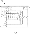
- Fig.1 shows a first circuit 1 for operating a household appliance in the form of a first oven B1 under several operating modes.
- the oven B1 has several radiators for heating a cooking space (not shown), namely here, for example, a first top heat or grill heater 2, a second top heat or grill heater 3, a bottom heat radiator 4 and a circulating air or ring heater 5.
- Die Radiators 2 to 5 are electrically connected on the one hand to an outer conductor L and on the other hand to a neutral conductor N.
- other voltage connections are also possible, eg to a DC voltage source, eg with 230 volts.
- the radiators 2 to 5 are arranged here, for example, electrically parallel to one another.
- An evaporator 6 is connected in parallel with the radiators 2 to 5 as a further consumer.
- the evaporator 6 can have a steam generating heater.
- the steam generating heater can be the only electrical consumer of the evaporator 6.
- the steam generating radiator can e.g. heat an evaporator dish embedded in a floor of the cooking space so that water poured into the dish can evaporate directly into the cooking space.
- a heating circuit relay K1.1 and a temperature limiter 7 are connected in series between the consumers 2 to 6 (i.e. the radiators 2 to 5 and the evaporator 6) and the neutral conductor N. Furthermore, between the outer conductor L and the consumers 2 to 6 in series: a mechanical rotary selector switch 8, a main relay K1.2 and a mechanical oven controller in the form of a mechanical thermostat - here e.g. formed as a user-operated capillary tube regulator 9 - switched.
- the heating circuit relay K1.1 and the main relay K1.2 are components of a clock circuit K1.
- the clock circuit K1 is constructed as an electronic circuit and, in addition to the two relays K1.1 and K1.2, can have at least one integrated circuit (e.g. a microcontroller, not shown) etc.
- the clock circuit K1 is used, among other things, to control the time of the oven B1 (e.g. to implement a timer function and to display the time) and can also have an oscillator or clock generator (not shown).
- the clock circuit K1 can also have a display device (not shown, e.g. a 7-segment display).
- the clock circuit K1 can cause a time-delayed and / or time-limited operation by closing or opening the main relay K1.2.
- the clock circuit K1 is connected here directly between the outer conductor L and the neutral conductor N and therefore - except when the entire oven 1 is switched off at a main switch (not shown) - can always be operated.
- the clock circuit K1 can then display a time when the rotary selector switch 8 is in its off position.
- a first individual switch 8.1 is arranged electrically between the outer conductor L and the main relay K1.2.
- a second individual switch 8.2 is electrically connected between the consumers 2 to 6 and the capillary tube regulator 9. By means of the second individual switch 8.2, a respective individual combination of the consumers 2 to 6 can be electrically connected to the capillary tube regulator 9, depending on the rotational position.
- This group of switches 8.2-m could have, for example, a switch 8.2-2 arranged in series with the first top heat or grill heater 2, a switch 8.2-3 arranged in series with the second top heat or grill heater 3, etc.
- a third individual switch 8.3 is electrically connected between the neutral conductor N and the temperature limiter 7.
- a fourth individual switch 8.4 is electrically connected between the second individual switch 8.2 and an input of the clock circuit K1.
- a fifth individual switch 8.5 is electrically connected in series with a circulating air motor 10 of a circulating air blower between the third individual switch 8.3 and the heating relay K1.2, so that the circulating air motor 10 can also be operated independently of the consumers 2 to 6.
- a sixth individual switch 8.6 is connected between the fifth individual switch 8.5 and the capillary tube regulator 9 and thus - via the capillary tube regulator 9 - is connected in parallel to the air motor 10.
- An oven lamp 11 is connected directly between the main relay K1.2 and the third individual switch 8.3.
- a signal lamp 12 is connected directly between the heating circuit relay K1.1 and the capillary tube regulator 9. Furthermore, a seventh individual switch 8.7 is electrically connected in series with a cooling fan 13 directly between the outer conductor L and the neutral conductor N. Another temperature limiter 14 is connected in parallel with the seventh individual switch 8.7 and electrically in series with the cooling fan 13.
- the consumers 2 to 6 and 10 to 12 are therefore electrically connected in series with the main relay K1.2, so that they are not supplied with electrical energy when the main relay K1.2 is open and are consequently switched off. Only the clock circuit K1 and the cooling fan 13 can be operated even when the main relay K1.2 is open.
- the rotary selector switch 8 can be set up in such a way that all the individual switches 8.n are open.
- the individual switches 8.n can, for example, by means of a suitable, e.g. connected to a rotary knob, operated shaft.
- any but fixed combination of the closed states (open / closed) of the individual switches 8.n can be assigned to each selected position of the rotary selector switch 8.
- a user turns the rotary selector switch 8 from its off or zero position to an operating position which corresponds to an operating mode desired by the user.
- the operating mode can e.g. a grill mode, a bottom heat and / or top heat mode or a recirculation mode.
- the heating circuit relay K1.1 is permanently closed during operation.
- the rotary selector switch 8 closes the individual switches 8.1 to 8.4.
- the second individual switch 8.2 is closed between the grill radiators 2 and / or 3 and the capillary tube regulator 9.
- the individual switches 8.5 to 8.7 can be open. Closing the individual switches 8.1 to 8.3 has the effect that the circuit of the grill radiators 2 and / or 3 can be opened and closed by means of the capillary tube regulator 9 in order to regulate an actual cooking space temperature to a target cooking space temperature set by the capillary tube regulator 9.
- the closed individual switch 8.4 has the effect that the clock circuit K1 can recognize or receive feedback that a heating operation has been set on the rotary selector switch 8.
- the clock circuit K1 can then implement, for example, a delay time until the start of the food processing or cooking process and / or a cooking time, in particular by correspondingly switching the main relay K1.2 on or off.
- the delay time and the cooking time may have been entered beforehand by a user, for example via an input device provided on the clock circuit K1 or connected to the clock circuit (not shown). Without entering a delay time and / or a cooking time, the clock circuit K1 keeps the main relay K1.2 permanently closed when the individual switch 8.4 is closed. After the cooking or heating mode has ended, the cooling fan 13 can still be operated in a "run-on mode" by closing the seventh individual switch 8.7.
- the second individual switch 8.2 can be set such that only the air circulation heater 5 can be operated.
- the fifth individual switch 8.5 must be closed in order to also be able to operate the air-motor 10.
- the evaporator 6 and at least one of the heating elements 2 to 5 can be switched on or operated.
- the evaporator 6 is energized in accordance with the radiator 2 to 5 that is switched on, namely depending on an open position (open / closed) of the capillary tube regulator 9.
- an input of the clock circuit K1 is connected to an output of the rotary selector switch 8.
- the rotary selector 8 is equipped with a coding device (e.g. in the form of a coding switch board, e.g. based on a coding using a gray code, not shown), which assigns a unique output signal or a unique electrical interface configuration to each rotary position of the rotary selector 8 .
- the clock circuit K1 can also change the off position of the rotary selector switch 8 by means of a corresponding gray code - e.g. "000" - recognize.
- the clock circuit K1 can recognize (for example by means of suitable evaluation logic or evaluation circuit) in which rotary position the rotary selector switch 8 is located.
- a rotary position of the rotary selector switch 8 can in particular correspond to a respective operating mode.
- the clock circuit K1 processes the gray code (e.g. by means of a corresponding processing device) and can e.g. Switch the heating circuit relay K1.1 now optionally also during operation of an operating mode selected on the rotary selector switch 8.
- the heating circuit relay K1.1 can be switched clocked by means of the clock circuit K1, so that the suitable radiators 2 to 5 and the evaporator 8 are also supplied with current in a clocked manner.
- the clock or basic clock already available for providing a clock function can be used as the basis for the clock of the heating circuit relay K1.1.
- Such clocked operation with clocked heating circuit relay K1.1 can also be referred to as a "special operating mode".
- the clock circuit K1 can determine or determine the timing parameters suitable for the selected special operating mode (period duration, duty cycle, etc.) on the basis of the gray code transmitted or read out by the rotary selector switch 8.
- the capillary tube regulator 9 can be set by a user to a temperature value (at which the capillary tube regulator 9 opens or interrupts), which serves as an upper threshold value for the temperature value achievable in the clocked special operating mode.
- the capillary tube regulator 9 may have been set by a user to a temperature value which is above a temperature value typically achievable in the clocked special operating mode, for example to a maximum adjustable temperature value.
- the oven 1 can carry out at least one "manual" operating mode with a mechanical-thermal control via the mechanically adjustable rotary selector switch 8 and the capillary tube regulator 9 and in at least one further ("special") operating mode a clocked controlled heating operation in a simple and particularly inexpensive manner carry out.
- a function e.g. an energy saving mode or a soft mode, are offered in cooking devices with a mechanical control.
- the electronic unit designed here as a clock circuit K1 can be kept particularly simple, since basic functionalities (temperature setting, temperature measurement and control), in particular for conventional operating modes, are already covered by the very inexpensive mechanical control element (e.g. the capillary tube controller 9).
- Fig.2 shows a second circuit 21 of a second oven B2.
- the circuit 21 differs from the circuit 1 in that the evaporator 6 is no longer connected in series with the capillary tube regulator 9, but in parallel with the radiators 2 to 5 and the capillary tube regulator 9.
- the rotary selector switch 8 has two further individual switches, namely an eighth individual switch 8.8 and a ninth Single switch 8.9.
- the eighth individual switch 8.8 emerges instead of the heating circuit relay K1.1 Fig.1 and is thus connected between the temperature limiter 7 and the radiators 2 to 5.
- the heating circuit relay K1.1 is now connected on the one hand between the temperature limiter 7 and the eighth individual switch 8.8 and on the other hand connected to the evaporator 6.
- the ninth individual switch 8.9 is connected on the one hand between the eighth individual switch 8.8 and the radiators 2 to 5 and on the other hand between the heating circuit relay K1.1 and the evaporator 6.
- the individual switch 8.2 can be set such that the circuit of the evaporator 6 is open. In a switch position, the eighth individual switch 8.8 can then be opened, the heating circuit relay K1.1 closed and the ninth individual switch 8.9 closed. Current can then flow as before through the heating circuit relay K1.1, which is kept closed during operation, to the radiators 2 to 5. In an alternative switching position e.g. the eighth individual switch 8.8 is closed and the ninth individual switch 8.9 and the heating circuit relay K1.1 are open.
- the fifth individual switch 8.5 can be closed in both switching positions in order to be able to operate the air-motor 10.
- the eighth individual switch 8.8 is open and the ninth individual switch 8.9 is closed.
- the individual switch 8.2 can be set such that only the circulating air heating element 5 can be operated.
- the fifth individual switch 8.5 is also closed in order to be able to operate the circulating air motor 10. With the clocked switching of the heating circuit relay K1.1, the circulating air heater 5 is operated clocked.
- the eighth individual switch 8.8 can be closed and the ninth individual switch 8.9 can be opened.
- the individual switch 8.2 can be set such that the circulating air heater 5 and the evaporator 6 can be operated.
- the fifth individual switch 8.5 is also closed in order to be able to operate the circulating air motor 10.
- the circulating air heater 5 is switched on and off via the capillary tube regulator 9 as is conventional can be switched off in order to regulate the cooking space temperature to a desired value specified by the capillary tube regulator 9.
- the evaporator 6 is supplied with current in a clocked manner by switching the heating circuit relay K1.1.
- the heating circuit relay K1.1 does not even have to be switched clocked, but can also be switched in another, for example irregular, way.
- a number can also include the specified number as well as a usual tolerance range, as long as this is not explicitly excluded.
Landscapes
- Engineering & Computer Science (AREA)
- Chemical & Material Sciences (AREA)
- Combustion & Propulsion (AREA)
- Mechanical Engineering (AREA)
- General Engineering & Computer Science (AREA)
- Food Science & Technology (AREA)
- Physics & Mathematics (AREA)
- Electromagnetism (AREA)
- Electric Stoves And Ranges (AREA)
Priority Applications (1)
| Application Number | Priority Date | Filing Date | Title |
|---|---|---|---|
| PL17172025T PL3250002T3 (pl) | 2016-05-25 | 2017-05-19 | Domowe urządzenie do gotowania |
Applications Claiming Priority (1)
| Application Number | Priority Date | Filing Date | Title |
|---|---|---|---|
| DE102016209147.6A DE102016209147A1 (de) | 2016-05-25 | 2016-05-25 | Haushalts-Gargerät |
Publications (2)
| Publication Number | Publication Date |
|---|---|
| EP3250002A1 EP3250002A1 (de) | 2017-11-29 |
| EP3250002B1 true EP3250002B1 (de) | 2019-12-18 |
Family
ID=58738974
Family Applications (1)
| Application Number | Title | Priority Date | Filing Date |
|---|---|---|---|
| EP17172025.3A Active EP3250002B1 (de) | 2016-05-25 | 2017-05-19 | Haushalts-gargerät |
Country Status (4)
| Country | Link |
|---|---|
| EP (1) | EP3250002B1 (pl) |
| DE (1) | DE102016209147A1 (pl) |
| ES (1) | ES2764426T3 (pl) |
| PL (1) | PL3250002T3 (pl) |
Cited By (1)
| Publication number | Priority date | Publication date | Assignee | Title |
|---|---|---|---|---|
| EP4430917A4 (en) * | 2021-11-08 | 2025-09-10 | Mamur Teknoloji Sistemleri San A S | OVEN TEMPERATURE CONTROL SYSTEM |
Families Citing this family (3)
| Publication number | Priority date | Publication date | Assignee | Title |
|---|---|---|---|---|
| DE102019202389A1 (de) * | 2019-02-21 | 2020-08-27 | BSH Hausgeräte GmbH | Gargerät mit Dampfbehandlungsfunktion |
| DE102019216955A1 (de) * | 2019-11-04 | 2021-05-06 | BSH Hausgeräte GmbH | Gargerätesteuerung mit Betriebsartenschalter und Schaltuhr |
| DE102022119502B4 (de) * | 2022-08-03 | 2025-06-05 | Welbilt Deutschland GmbH | Gargerät |
Family Cites Families (12)
| Publication number | Priority date | Publication date | Assignee | Title |
|---|---|---|---|---|
| DE3204543C2 (de) * | 1982-02-10 | 1987-01-29 | Bosch Siemens Hausgeraete | Schaltungsanordnung für Heizelemente in einer Kochherdmulde |
| DE3545108A1 (de) * | 1985-12-19 | 1987-07-09 | Bosch Siemens Hausgeraete | Herdsteuerschaltung zum garen von speisen |
| DE4228769C2 (de) | 1992-08-28 | 2000-11-16 | Bsh Bosch Siemens Hausgeraete | Backofen mit einem Temperaturfühler zur Bratautomatik-Regelung |
| DE10151937A1 (de) * | 2001-10-22 | 2003-04-30 | Bsh Bosch Siemens Hausgeraete | Gargerät mit einer Schnellaufheizeinheit |
| DE20118291U1 (de) | 2001-11-10 | 2003-03-20 | Diehl AKO Stiftung & Co. KG, 88239 Wangen | Herdschaltuhr mit Temperaturfühler |
| ATE327480T1 (de) | 2001-12-31 | 2006-06-15 | Electrolux Abp | Verfahren zur steuerung der energieaufnahme in einem backofen |
| DE10235015A1 (de) | 2002-08-01 | 2004-02-19 | Electrolux Home Products Corporation N.V. | Verfahren und Vorrichtung zur zeitlichen Steuerung eines Haushaltsgerätes |
| DE10260019B4 (de) * | 2002-12-19 | 2005-11-24 | Miele & Cie. Kg | Haushalts-Speisenwärmer zum Warmhalten von Speisen und Getränken |
| DE102004032074C5 (de) | 2004-07-02 | 2013-07-04 | Diehl Ako Stiftung & Co. Kg | Herdschaltuhr |
| DE102006022323A1 (de) * | 2006-05-12 | 2007-11-15 | BSH Bosch und Siemens Hausgeräte GmbH | Schaltungsanordnung und Verfahren zum Betreiben der Schaltungsanordnung |
| DE102007056714A1 (de) | 2007-11-26 | 2009-05-28 | BSH Bosch und Siemens Hausgeräte GmbH | Verfahren zum Betrieb eines Gargeräts und Gargerät |
| DE102011017638A1 (de) | 2011-04-27 | 2012-10-31 | BSH Bosch und Siemens Hausgeräte GmbH | Verfahren zum Betreiben eines Gargeräts sowie Steuer- und Regeleinrichtung für ein Gargerät und Gargerät |
-
2016
- 2016-05-25 DE DE102016209147.6A patent/DE102016209147A1/de not_active Withdrawn
-
2017
- 2017-05-19 ES ES17172025T patent/ES2764426T3/es active Active
- 2017-05-19 PL PL17172025T patent/PL3250002T3/pl unknown
- 2017-05-19 EP EP17172025.3A patent/EP3250002B1/de active Active
Non-Patent Citations (1)
| Title |
|---|
| None * |
Cited By (1)
| Publication number | Priority date | Publication date | Assignee | Title |
|---|---|---|---|---|
| EP4430917A4 (en) * | 2021-11-08 | 2025-09-10 | Mamur Teknoloji Sistemleri San A S | OVEN TEMPERATURE CONTROL SYSTEM |
Also Published As
| Publication number | Publication date |
|---|---|
| DE102016209147A1 (de) | 2017-11-30 |
| EP3250002A1 (de) | 2017-11-29 |
| ES2764426T3 (es) | 2020-06-03 |
| PL3250002T3 (pl) | 2020-06-01 |
Similar Documents
| Publication | Publication Date | Title |
|---|---|---|
| EP2653788B1 (de) | Kombigargerät | |
| EP3250002B1 (de) | Haushalts-gargerät | |
| EP2063180B1 (de) | Verfahren zum Betrieb eines Gargeräts und Gargerät | |
| DE10128369B4 (de) | Gargerät mit einem Wrasenlüfter | |
| EP2347631B1 (de) | Elektrische bügelvorrichtung mit automatischem an-/abschaltungssystem | |
| DE3229193A1 (de) | Energieregler fuer haushaltsherde | |
| EP3249302B1 (de) | Haushalts-gargerät | |
| EP0828406B1 (de) | Vorrichtung zur Begrenzung und Verteilung der von einem Herd aufgenommenen elektrischen Leistung | |
| DE10128370B4 (de) | Gargerät mit einem Kühllüfter | |
| EP2837890A2 (de) | Verfahren zum Betrieb eines Gasbackofens und Gasbackofen | |
| EP1513374B1 (de) | Wärmelade | |
| DE2705528A1 (de) | Vorrichtung zum steuern von vorzugsweise elektrischen heizgeraeten | |
| EP2518410A2 (de) | Verfahren zum Betreiben eines Gargeräts sowie Steuer- und Regeleinrichtung für ein Gargerät und Gargerät | |
| DE4104677A1 (de) | Verfahren zur automatischen leistungsanpassung | |
| EP3250001B1 (de) | Haushalts-gargerät | |
| DE102007008893A1 (de) | Hausgerät mit einem versenkbaren Bedienelement und Verfahren zum Bedienen eines derartigen Hausgeräts | |
| EP3816517B1 (de) | Gargerätesteuerung mit betriebsartenschalter und schaltuhr | |
| DE102014201427A1 (de) | Garofenvorrichtung | |
| EP2896889B1 (de) | Verfahren zum betreiben eines gargeräts mit einem kochfeld und gargerät | |
| DE3703884A1 (de) | Verzoegerungsschaltung | |
| DE2715768C2 (de) | Betriebsschaltung für eine Haushaltskocheinrichtung | |
| EP2074922A2 (de) | Haushaltgerät, insbesondere Geschirrspüler, mit getaktetem Durchlauf-Erhitzer | |
| DE102004032074C5 (de) | Herdschaltuhr | |
| DE2455579A1 (de) | Verfahren und anordnung zum betrieb eines elektrisch beheizten haushaltbackofens | |
| DE102019202389A1 (de) | Gargerät mit Dampfbehandlungsfunktion |
Legal Events
| Date | Code | Title | Description |
|---|---|---|---|
| PUAI | Public reference made under article 153(3) epc to a published international application that has entered the european phase |
Free format text: ORIGINAL CODE: 0009012 |
|
| STAA | Information on the status of an ep patent application or granted ep patent |
Free format text: STATUS: THE APPLICATION HAS BEEN PUBLISHED |
|
| AK | Designated contracting states |
Kind code of ref document: A1 Designated state(s): AL AT BE BG CH CY CZ DE DK EE ES FI FR GB GR HR HU IE IS IT LI LT LU LV MC MK MT NL NO PL PT RO RS SE SI SK SM TR |
|
| AX | Request for extension of the european patent |
Extension state: BA ME |
|
| STAA | Information on the status of an ep patent application or granted ep patent |
Free format text: STATUS: REQUEST FOR EXAMINATION WAS MADE |
|
| 17P | Request for examination filed |
Effective date: 20180529 |
|
| RBV | Designated contracting states (corrected) |
Designated state(s): AL AT BE BG CH CY CZ DE DK EE ES FI FR GB GR HR HU IE IS IT LI LT LU LV MC MK MT NL NO PL PT RO RS SE SI SK SM TR |
|
| GRAP | Despatch of communication of intention to grant a patent |
Free format text: ORIGINAL CODE: EPIDOSNIGR1 |
|
| STAA | Information on the status of an ep patent application or granted ep patent |
Free format text: STATUS: GRANT OF PATENT IS INTENDED |
|
| INTG | Intention to grant announced |
Effective date: 20190807 |
|
| GRAS | Grant fee paid |
Free format text: ORIGINAL CODE: EPIDOSNIGR3 |
|
| GRAA | (expected) grant |
Free format text: ORIGINAL CODE: 0009210 |
|
| STAA | Information on the status of an ep patent application or granted ep patent |
Free format text: STATUS: THE PATENT HAS BEEN GRANTED |
|
| AK | Designated contracting states |
Kind code of ref document: B1 Designated state(s): AL AT BE BG CH CY CZ DE DK EE ES FI FR GB GR HR HU IE IS IT LI LT LU LV MC MK MT NL NO PL PT RO RS SE SI SK SM TR |
|
| REG | Reference to a national code |
Ref country code: CH Ref legal event code: EP |
|
| REG | Reference to a national code |
Ref country code: IE Ref legal event code: FG4D Free format text: LANGUAGE OF EP DOCUMENT: GERMAN |
|
| REG | Reference to a national code |
Ref country code: DE Ref legal event code: R096 Ref document number: 502017003155 Country of ref document: DE |
|
| REG | Reference to a national code |
Ref country code: AT Ref legal event code: REF Ref document number: 1216042 Country of ref document: AT Kind code of ref document: T Effective date: 20200115 |
|
| REG | Reference to a national code |
Ref country code: NL Ref legal event code: MP Effective date: 20191218 |
|
| PG25 | Lapsed in a contracting state [announced via postgrant information from national office to epo] |
Ref country code: LV Free format text: LAPSE BECAUSE OF FAILURE TO SUBMIT A TRANSLATION OF THE DESCRIPTION OR TO PAY THE FEE WITHIN THE PRESCRIBED TIME-LIMIT Effective date: 20191218 Ref country code: SE Free format text: LAPSE BECAUSE OF FAILURE TO SUBMIT A TRANSLATION OF THE DESCRIPTION OR TO PAY THE FEE WITHIN THE PRESCRIBED TIME-LIMIT Effective date: 20191218 Ref country code: NO Free format text: LAPSE BECAUSE OF FAILURE TO SUBMIT A TRANSLATION OF THE DESCRIPTION OR TO PAY THE FEE WITHIN THE PRESCRIBED TIME-LIMIT Effective date: 20200318 Ref country code: GR Free format text: LAPSE BECAUSE OF FAILURE TO SUBMIT A TRANSLATION OF THE DESCRIPTION OR TO PAY THE FEE WITHIN THE PRESCRIBED TIME-LIMIT Effective date: 20200319 Ref country code: BG Free format text: LAPSE BECAUSE OF FAILURE TO SUBMIT A TRANSLATION OF THE DESCRIPTION OR TO PAY THE FEE WITHIN THE PRESCRIBED TIME-LIMIT Effective date: 20200318 Ref country code: FI Free format text: LAPSE BECAUSE OF FAILURE TO SUBMIT A TRANSLATION OF THE DESCRIPTION OR TO PAY THE FEE WITHIN THE PRESCRIBED TIME-LIMIT Effective date: 20191218 Ref country code: LT Free format text: LAPSE BECAUSE OF FAILURE TO SUBMIT A TRANSLATION OF THE DESCRIPTION OR TO PAY THE FEE WITHIN THE PRESCRIBED TIME-LIMIT Effective date: 20191218 |
|
| REG | Reference to a national code |
Ref country code: LT Ref legal event code: MG4D |
|
| PG25 | Lapsed in a contracting state [announced via postgrant information from national office to epo] |
Ref country code: RS Free format text: LAPSE BECAUSE OF FAILURE TO SUBMIT A TRANSLATION OF THE DESCRIPTION OR TO PAY THE FEE WITHIN THE PRESCRIBED TIME-LIMIT Effective date: 20191218 Ref country code: HR Free format text: LAPSE BECAUSE OF FAILURE TO SUBMIT A TRANSLATION OF THE DESCRIPTION OR TO PAY THE FEE WITHIN THE PRESCRIBED TIME-LIMIT Effective date: 20191218 |
|
| REG | Reference to a national code |
Ref country code: ES Ref legal event code: FG2A Ref document number: 2764426 Country of ref document: ES Kind code of ref document: T3 Effective date: 20200603 |
|
| PG25 | Lapsed in a contracting state [announced via postgrant information from national office to epo] |
Ref country code: AL Free format text: LAPSE BECAUSE OF FAILURE TO SUBMIT A TRANSLATION OF THE DESCRIPTION OR TO PAY THE FEE WITHIN THE PRESCRIBED TIME-LIMIT Effective date: 20191218 |
|
| PG25 | Lapsed in a contracting state [announced via postgrant information from national office to epo] |
Ref country code: RO Free format text: LAPSE BECAUSE OF FAILURE TO SUBMIT A TRANSLATION OF THE DESCRIPTION OR TO PAY THE FEE WITHIN THE PRESCRIBED TIME-LIMIT Effective date: 20191218 Ref country code: EE Free format text: LAPSE BECAUSE OF FAILURE TO SUBMIT A TRANSLATION OF THE DESCRIPTION OR TO PAY THE FEE WITHIN THE PRESCRIBED TIME-LIMIT Effective date: 20191218 Ref country code: CZ Free format text: LAPSE BECAUSE OF FAILURE TO SUBMIT A TRANSLATION OF THE DESCRIPTION OR TO PAY THE FEE WITHIN THE PRESCRIBED TIME-LIMIT Effective date: 20191218 Ref country code: PT Free format text: LAPSE BECAUSE OF FAILURE TO SUBMIT A TRANSLATION OF THE DESCRIPTION OR TO PAY THE FEE WITHIN THE PRESCRIBED TIME-LIMIT Effective date: 20200513 Ref country code: NL Free format text: LAPSE BECAUSE OF FAILURE TO SUBMIT A TRANSLATION OF THE DESCRIPTION OR TO PAY THE FEE WITHIN THE PRESCRIBED TIME-LIMIT Effective date: 20191218 |
|
| PG25 | Lapsed in a contracting state [announced via postgrant information from national office to epo] |
Ref country code: SM Free format text: LAPSE BECAUSE OF FAILURE TO SUBMIT A TRANSLATION OF THE DESCRIPTION OR TO PAY THE FEE WITHIN THE PRESCRIBED TIME-LIMIT Effective date: 20191218 Ref country code: SK Free format text: LAPSE BECAUSE OF FAILURE TO SUBMIT A TRANSLATION OF THE DESCRIPTION OR TO PAY THE FEE WITHIN THE PRESCRIBED TIME-LIMIT Effective date: 20191218 Ref country code: IS Free format text: LAPSE BECAUSE OF FAILURE TO SUBMIT A TRANSLATION OF THE DESCRIPTION OR TO PAY THE FEE WITHIN THE PRESCRIBED TIME-LIMIT Effective date: 20200418 |
|
| REG | Reference to a national code |
Ref country code: DE Ref legal event code: R097 Ref document number: 502017003155 Country of ref document: DE |
|
| PLBE | No opposition filed within time limit |
Free format text: ORIGINAL CODE: 0009261 |
|
| STAA | Information on the status of an ep patent application or granted ep patent |
Free format text: STATUS: NO OPPOSITION FILED WITHIN TIME LIMIT |
|
| PG25 | Lapsed in a contracting state [announced via postgrant information from national office to epo] |
Ref country code: DK Free format text: LAPSE BECAUSE OF FAILURE TO SUBMIT A TRANSLATION OF THE DESCRIPTION OR TO PAY THE FEE WITHIN THE PRESCRIBED TIME-LIMIT Effective date: 20191218 |
|
| 26N | No opposition filed |
Effective date: 20200921 |
|
| PG25 | Lapsed in a contracting state [announced via postgrant information from national office to epo] |
Ref country code: SI Free format text: LAPSE BECAUSE OF FAILURE TO SUBMIT A TRANSLATION OF THE DESCRIPTION OR TO PAY THE FEE WITHIN THE PRESCRIBED TIME-LIMIT Effective date: 20191218 |
|
| PG25 | Lapsed in a contracting state [announced via postgrant information from national office to epo] |
Ref country code: LI Free format text: LAPSE BECAUSE OF NON-PAYMENT OF DUE FEES Effective date: 20200531 Ref country code: MC Free format text: LAPSE BECAUSE OF FAILURE TO SUBMIT A TRANSLATION OF THE DESCRIPTION OR TO PAY THE FEE WITHIN THE PRESCRIBED TIME-LIMIT Effective date: 20191218 Ref country code: IT Free format text: LAPSE BECAUSE OF FAILURE TO SUBMIT A TRANSLATION OF THE DESCRIPTION OR TO PAY THE FEE WITHIN THE PRESCRIBED TIME-LIMIT Effective date: 20191218 Ref country code: CH Free format text: LAPSE BECAUSE OF NON-PAYMENT OF DUE FEES Effective date: 20200531 |
|
| REG | Reference to a national code |
Ref country code: BE Ref legal event code: MM Effective date: 20200531 |
|
| PG25 | Lapsed in a contracting state [announced via postgrant information from national office to epo] |
Ref country code: LU Free format text: LAPSE BECAUSE OF NON-PAYMENT OF DUE FEES Effective date: 20200519 |
|
| PG25 | Lapsed in a contracting state [announced via postgrant information from national office to epo] |
Ref country code: IE Free format text: LAPSE BECAUSE OF NON-PAYMENT OF DUE FEES Effective date: 20200519 Ref country code: FR Free format text: LAPSE BECAUSE OF NON-PAYMENT OF DUE FEES Effective date: 20200531 |
|
| PG25 | Lapsed in a contracting state [announced via postgrant information from national office to epo] |
Ref country code: BE Free format text: LAPSE BECAUSE OF NON-PAYMENT OF DUE FEES Effective date: 20200531 |
|
| PG25 | Lapsed in a contracting state [announced via postgrant information from national office to epo] |
Ref country code: MT Free format text: LAPSE BECAUSE OF FAILURE TO SUBMIT A TRANSLATION OF THE DESCRIPTION OR TO PAY THE FEE WITHIN THE PRESCRIBED TIME-LIMIT Effective date: 20191218 Ref country code: CY Free format text: LAPSE BECAUSE OF FAILURE TO SUBMIT A TRANSLATION OF THE DESCRIPTION OR TO PAY THE FEE WITHIN THE PRESCRIBED TIME-LIMIT Effective date: 20191218 |
|
| PG25 | Lapsed in a contracting state [announced via postgrant information from national office to epo] |
Ref country code: MK Free format text: LAPSE BECAUSE OF FAILURE TO SUBMIT A TRANSLATION OF THE DESCRIPTION OR TO PAY THE FEE WITHIN THE PRESCRIBED TIME-LIMIT Effective date: 20191218 |
|
| REG | Reference to a national code |
Ref country code: AT Ref legal event code: MM01 Ref document number: 1216042 Country of ref document: AT Kind code of ref document: T Effective date: 20220519 |
|
| PG25 | Lapsed in a contracting state [announced via postgrant information from national office to epo] |
Ref country code: AT Free format text: LAPSE BECAUSE OF NON-PAYMENT OF DUE FEES Effective date: 20220519 |
|
| PGFP | Annual fee paid to national office [announced via postgrant information from national office to epo] |
Ref country code: PL Payment date: 20250507 Year of fee payment: 9 Ref country code: DE Payment date: 20250531 Year of fee payment: 9 |
|
| PGFP | Annual fee paid to national office [announced via postgrant information from national office to epo] |
Ref country code: ES Payment date: 20250616 Year of fee payment: 9 Ref country code: GB Payment date: 20250522 Year of fee payment: 9 |
|
| PGFP | Annual fee paid to national office [announced via postgrant information from national office to epo] |
Ref country code: TR Payment date: 20250509 Year of fee payment: 9 |